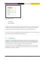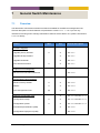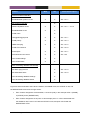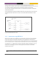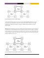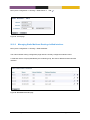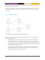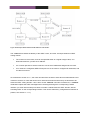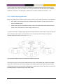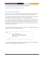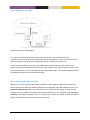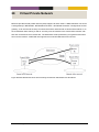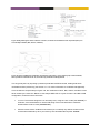
1
Management guide MES switches operating system This guide describes the functionality and the management features of the MES Operating System (MES-OS). MES-OS is the firmware controlling the operation on the MES series Teleste switches. MES-OS Management guide, 59300523, Ver 4.11.1-0 Table of Content TABLE OF CONTENT .......................................................................................................................................... 1 1 INTRODUCTION MES-OS MANAGEMENT METHODS ................................................................................ 1 1.1 INTRODUCTION............................................................................................................................................... 1 1.2 WHERE TO FIND MORE INFORMATION ................................................................................................................. 2 1.2.1 2 Factory default settings ..................................................................................................................... 2 QUICK START ........................................................................................................................................... 3 2.1 STARTING THE SWITCH FOR THE FIRST TIME – FACTORY DEFAULT SETTING ................................................................ 3 2.2 MODIFYING THE IP SETTING.............................................................................................................................. 4 3 3.1 4 2.2.1 Using the Web Interface to Update the Switch IP Settings ............................................................... 4 2.2.2 Using the CLI to Update the Switch IP Settings ................................................................................. 7 OVERVIEW OF MANAGEMENT METHODS .............................................................................................. 14 SELECTING A MANAGEMENT TOOL ................................................................................................................... 14 3.1.1 When to use the Web Management Tool ....................................................................................... 14 3.1.2 When to use the Command Line Tool.............................................................................................. 15 MANAGEMENT VIA WEB INTERFACE ..................................................................................................... 16 4.1 DOCUMENT CONVENTIONS ............................................................................................................................. 17 4.2 LOGGING IN ................................................................................................................................................. 17 4.3 NAVIGATION ................................................................................................................................................ 18 4.4 SYSTEM OVERVIEW ....................................................................................................................................... 23 4.4.1 System Overview - Summary ........................................................................................................... 23 4.4.2 System Overview Detailed ............................................................................................................... 25 MES-OS Management Guide Table of Content • 1 5 MANAGEMENT VIA COMMAND LINE INTERFACE (CLI) ........................................................................... 28 5.1 OVERVIEW OF THE MES-OS CLI HIERARCHY ...................................................................................................... 28 5.2 ACCESSING THE COMMAND LINE INTERFACE ....................................................................................................... 29 5.3 5.4 5.2.1 Accessing CLI via console port ......................................................................................................... 29 5.2.2 Accessing the CLI via SSH or Telnet ................................................................................................. 32 USING THE CLI ............................................................................................................................................. 33 5.3.1 Starting out with the CLI.................................................................................................................. 33 5.3.2 Entering and leaving CLI contexts ................................................................................................... 36 5.3.3 CLI command conventions............................................................................................................... 38 GENERAL CLI COMMANDS .............................................................................................................................. 39 5.4.1 Negate/disable a setting ................................................................................................................. 39 5.4.2 Execute (do) command from Admin Exec context ........................................................................... 39 5.4.3 End context...................................................................................................................................... 40 5.4.4 Leave context .................................................................................................................................. 40 5.4.5 Abort context................................................................................................................................... 40 5.4.6 Logout ............................................................................................................................................. 41 5.4.7 Repeat a command ......................................................................................................................... 41 5.4.8 On-line help ..................................................................................................................................... 41 5.4.9 CLI tutorial ....................................................................................................................................... 41 5.4.10 6 6.1 Entering Global Configuration Context ....................................................................................... 42 MES-OS SNMP SUPPORT ........................................................................................................................ 43 SNMP INTRODUCTION AND FEATURE OVERVIEW ................................................................................................ 43 6.1.1 SNMP introduction .......................................................................................................................... 43 6.1.2 SNMP Communities ......................................................................................................................... 44 6.1.3 Trap Support .................................................................................................................................... 45 6.1.4 Secure management using SNMPv3 ............................................................................................... 48 6.1.5 Supported MIBs ............................................................................................................................... 50 6.1.6 Recommended Management Software .......................................................................................... 51 MES-OS Management Guide Table of Content • 2 6.2 MANAGING SNMP VIA THE WEB INTERFACE ...................................................................................................... 52 6.2.1 6.3 7 7.1 Manage SNMP V3 Users ................................................................................................................. 53 MANAGE SNMP SETTINGS VIA THE CLI ............................................................................................................ 54 6.3.1 Manage SNMP Server ..................................................................................................................... 55 6.3.2 Manage SNMP Read Community .................................................................................................... 55 6.3.3 Manage SNMP Write Community ................................................................................................... 55 6.3.4 Manage SNMP Trap Community ..................................................................................................... 56 6.3.5 Manage SNMP Trap Hosts .............................................................................................................. 56 6.3.6 Manage SNMPv3 Read-Only User ................................................................................................... 57 6.3.7 Manage SNMPv3 Read-Write User ................................................................................................. 58 6.3.8 Show SNMP server status ................................................................................................................ 58 GENERAL SWITCH MAINTENANCE ......................................................................................................... 59 OVERVIEW................................................................................................................................................... 59 7.1.1 System Firmware ............................................................................................................................. 61 7.1.2 What to do if you cannot access your switch .................................................................................. 61 7.1.3 Configuration Files and Reboot ....................................................................................................... 64 7.1.4 Virtual File System ........................................................................................................................... 66 7.1.5 Automatic Backup and Restore to/from USB .................................................................................. 68 7.1.6 Configuration Deployment via USB ................................................................................................. 71 7.1.7 Certificate Management ................................................................................................................. 72 7.1.8 Managing LLDP ............................................................................................................................... 72 7.1.9 Maintenance and diagnostic tools .................................................................................................. 73 MES-OS Management Guide Table of Content • 3 7.2 MAINTENANCE VIA THE WEB INTERFACE ........................................................................................................... 74 7.2.1 Managing switch firmware via the Web Interface .......................................................................... 74 7.2.2 Port Monitoring ............................................................................................................................... 75 7.2.3 Backup and Restore ......................................................................................................................... 76 7.2.4 Factory Reset ................................................................................................................................... 77 7.2.5 Restart ............................................................................................................................................. 78 7.2.6 Managing certificates ..................................................................................................................... 78 7.2.7 Enable/disable LLDP via the web interface ..................................................................................... 81 7.2.8 Show LLDP Status via the web interface ......................................................................................... 81 7.2.9 Ping tool .......................................................................................................................................... 82 7.2.10 7.3 Traceroute tool ........................................................................................................................... 83 MAINTENANCE VIA THE CLI ............................................................................................................................ 84 7.3.1 Upgrading firmware ........................................................................................................................ 87 7.3.2 Show System Information ............................................................................................................... 88 7.3.3 List Configuration and Log Files....................................................................................................... 89 7.3.4 Copy, Store, Restore or Paste Files .................................................................................................. 89 7.3.5 Delete a Configuration File .............................................................................................................. 92 7.3.6 Show Configuration File (or other files) ........................................................................................... 92 7.3.7 Activate Auto-Backup ...................................................................................................................... 93 7.3.8 Manual Restore from USB ............................................................................................................... 93 7.3.9 Rebooting the Device ...................................................................................................................... 93 7.3.10 Import Certificate ........................................................................................................................ 94 7.3.11 List and show details of Certificates............................................................................................ 94 7.3.12 Ping ............................................................................................................................................. 95 7.3.13 Traceroute ................................................................................................................................... 96 7.3.14 Remote Login to another device (SSH Client) .............................................................................. 96 7.3.15 Remote Login to another device (Telnet Client) .......................................................................... 96 7.3.16 Manage Port Monitoring ............................................................................................................ 97 MES-OS Management Guide Table of Content • 4 7.3.17 Enable/disable Port Monitoring .................................................................................................. 97 7.3.18 Set Mirror Port ............................................................................................................................ 97 7.3.19 Set Monitored Ports .................................................................................................................... 97 7.3.20 Show Port Monitoring Settings ................................................................................................... 98 7.3.21 Show Monitor Destination Port .................................................................................................. 98 7.3.22 Show Monitor Source Ports......................................................................................................... 98 7.3.23 Manage LLDP settings ................................................................................................................ 98 7.3.24 Enable/disable LLDP .................................................................................................................... 99 7.3.25 Show LLDP Status ...................................................................................................................... 100 7.3.26 Enable/disable Web Management Interface ............................................................................ 101 7.3.27 Enable/disable SSH Service ....................................................................................................... 101 7.3.28 Enable/disable Telnet Service ................................................................................................... 101 7.3.29 Show Web Management Interface Setting ............................................................................... 102 7.3.30 Show SSH Server Settings .......................................................................................................... 102 7.3.31 Show Telnet Server Settings ...................................................................................................... 102 7.3.32 Show System Environment Sensors ........................................................................................... 102 7.3.33 Show System Uptime ................................................................................................................ 103 7.3.34 Show Memory Usage ................................................................................................................ 103 7.3.35 Show Running Processes ........................................................................................................... 103 7.3.36 Show Flash Partition Table........................................................................................................ 103 7.3.37 Update Flash Partition Table .................................................................................................... 104 MES-OS Management Guide Table of Content • 5 8 8.1 8.2 8.3 ETHERNET PORT MANAGEMENT.......................................................................................................... 105 OVERVIEW OF ETHERNET PORT MANAGEMENT ................................................................................................ 105 8.1.1 Port speed and duplex modes ....................................................................................................... 105 8.1.2 Flow control ................................................................................................................................... 106 8.1.3 Layer-2 priority support ................................................................................................................. 107 8.1.4 Link alarm ...................................................................................................................................... 109 8.1.5 Inbound/Ingress rate limiting ........................................................................................................ 110 8.1.6 Outbound/Egress traffic shaping .................................................................................................. 110 8.1.7 MDI/MDIX crossover ..................................................................................................................... 111 8.1.8 Fall-back default VID ..................................................................................................................... 111 MANAGING PORT SETTINGS VIA THE WEB INTERFACE .......................................................................................... 112 8.2.1 List Port Settings ............................................................................................................................ 112 8.2.2 Edit Port Settings ........................................................................................................................... 114 MANAGING PORT SETTINGS VIA THE CLI .......................................................................................................... 116 8.3.1 Managing Ports ............................................................................................................................. 118 8.3.2 Managing all Ports ........................................................................................................................ 118 8.3.3 Port enabling and disabling........................................................................................................... 118 8.3.4 Speed and duplex setting .............................................................................................................. 119 8.3.5 Flow-control setting ...................................................................................................................... 119 8.3.6 Port priority setting ....................................................................................................................... 120 8.3.7 Set port priority mode ................................................................................................................... 120 8.3.8 Link alarm ...................................................................................................................................... 121 8.3.9 Inbound rate limiting ..................................................................................................................... 121 8.3.10 Outbound traffic shaping .......................................................................................................... 122 8.3.11 Cable cross-over setting ............................................................................................................ 122 8.3.12 Adapting PHY Receiver to Shielded or Unshielded Cable .......................................................... 123 8.3.13 Enable/disable Low Power Mode on TX Data Signalling .......................................................... 123 8.3.14 Fall-back default VLAN .............................................................................................................. 124 MES-OS Management Guide Table of Content • 6 9 9.1 9.2 8.3.15 Show port configuration ........................................................................................................... 124 8.3.16 Show port configuration (all ports) ........................................................................................... 124 8.3.17 Show port enable/disable setting ............................................................................................. 125 8.3.18 Show speed and duplex setting................................................................................................. 125 8.3.19 Show flow-control setting ......................................................................................................... 125 8.3.20 Show port priority setting ......................................................................................................... 125 8.3.21 Show priority mode setting ....................................................................................................... 126 8.3.22 Show link alarm setting............................................................................................................. 126 8.3.23 Show inbound rate limit setting ................................................................................................ 126 8.3.24 Show outbound traffic shaping setting ..................................................................................... 126 8.3.25 Show cable cross-over setting ................................................................................................... 127 8.3.26 Show PHY Receiver Shielded/Unshielded Setting...................................................................... 127 8.3.27 Show Power Mode on TX Data Signalling ................................................................................. 127 8.3.28 Show fall-back default-vid setting ............................................................................................ 127 8.3.29 Show port status (all ports) ....................................................................................................... 128 ETHERNET STATISTICS .......................................................................................................................... 129 ETHERNET STATISTICS OVERVIEW ................................................................................................................... 129 9.1.1 Inbound Byte Counters .................................................................................................................. 131 9.1.2 Inbound Counters of Good Packets ............................................................................................... 131 9.1.3 Dropped Inbound Packets ............................................................................................................. 132 9.1.4 Erroneous Inbound Packets ........................................................................................................... 132 9.1.5 Outbound Byte Counters ............................................................................................................... 133 9.1.6 Outbound Packets Counters .......................................................................................................... 133 9.1.7 Dropped Outbound Packets .......................................................................................................... 134 9.1.8 Outbound Collision and Busy Medium Counters ........................................................................... 134 STATISTICS VIA THE WEB INTERFACE ................................................................................................................ 135 9.2.1 Statistics Overview ........................................................................................................................ 135 9.2.2 Detailed Statistics .......................................................................................................................... 137 MES-OS Management Guide Table of Content • 7 9.3 10 10.1 10.2 10.3 STATISTICS VIA THE CLI ................................................................................................................................ 139 9.3.1 Managing Ethernet Statistics ........................................................................................................ 140 9.3.2 List Current Ethernet Statistics ...................................................................................................... 140 9.3.3 Clear Ethernet Statistics ................................................................................................................ 140 9.3.4 Show Ethernet Statistics ................................................................................................................ 141 VIRTUAL LAN ....................................................................................................................................... 142 OVERVIEW OF VLAN PROPERTIES AND MANAGEMENT FEATURES ........................................................................ 142 10.1.1 Introduction to VLANs ............................................................................................................... 142 10.1.2 Supported number of VLANs and VLAN integrity ...................................................................... 146 10.1.3 Switch default VLAN.................................................................................................................. 147 10.1.4 VLAN Priority ............................................................................................................................. 147 10.1.5 IGMP Snooping and VLANs ....................................................................................................... 147 10.1.6 Mapping VLANs to a CPU channel ............................................................................................ 148 10.1.7 Dynamic VLANs ......................................................................................................................... 148 10.1.8 MAC forwarding database ........................................................................................................ 150 PORT-BASED NETWORK ACCESS CONTROL ........................................................................................................ 152 10.2.1 Authentication using IEEE 802.1X ............................................................................................. 153 10.2.2 Authentication based on MAC addresses ................................................................................. 155 MANAGING VLAN SETTINGS VIA THE WEB INTERFACE ........................................................................................ 156 10.3.1 Edit VLAN settings using the web interface .............................................................................. 158 10.3.2 Create a new VLAN using the web interface ............................................................................. 160 10.3.3 Managing Dynamic VLAN using the web interface................................................................... 161 10.3.4 Managing port-based access control using the web interface ................................................. 161 10.3.5 Edit port-based access control settings..................................................................................... 162 10.3.6 Port-based access control statistics .......................................................................................... 163 MES-OS Management Guide Table of Content • 8 10.4 MANAGING VLAN SETTINGS VIA THE CLI ........................................................................................................ 165 10.4.1 Managing MAC Forwarding Database Settings........................................................................ 166 10.4.2 Configure MAC Address Aging Timeout .................................................................................... 167 10.4.3 Configure Static MAC Filter Entries ........................................................................................... 167 10.4.4 Show MAC Forwarding Database Settings ............................................................................... 168 10.4.5 Managing general VLAN settings ............................................................................................. 168 10.4.6 Enable dynamic VLAN ............................................................................................................... 168 10.4.7 Managing individual VLANs ...................................................................................................... 169 10.4.8 Enable/disable a VLAN .............................................................................................................. 169 10.4.9 VLAN name ............................................................................................................................... 169 10.4.10 Manage untagged ports ........................................................................................................... 170 10.4.11 Manage tagged ports ............................................................................................................... 171 10.4.12 Manage forbidden ports ........................................................................................................... 171 10.4.13 VLAN priority setting ................................................................................................................. 172 10.4.14 VLAN IGMP Snooping ................................................................................................................ 172 10.4.15 CPU channel mapping ............................................................................................................... 172 10.4.16 IEEE 802.1X authentication ....................................................................................................... 173 10.4.17 MAC based authentication ....................................................................................................... 173 10.4.18 Except ports from authentication ............................................................................................. 173 10.4.19 Show VLAN configuration ......................................................................................................... 174 10.4.20 Show VLAN configuration (all VLANs) ....................................................................................... 174 10.4.21 Show dynamic VLAN setting ..................................................................................................... 174 10.4.22 Show VLAN enable/disable setting ........................................................................................... 175 10.4.23 Show VLAN name setting .......................................................................................................... 175 10.4.24 Show untagged ports setting .................................................................................................... 175 10.4.25 Show tagged ports setting ........................................................................................................ 175 10.4.26 Show VLAN priority setting ....................................................................................................... 176 10.4.27 Show IGMP snooping setting .................................................................................................... 176 MES-OS Management Guide Table of Content • 9 11 11.1 10.4.28 CPU channel mapping ............................................................................................................... 176 10.4.29 Show VLAN status (all VLANs) ................................................................................................... 176 10.4.30 Show Current MAC Forwarding Database ................................................................................ 177 10.4.31 Show IEEE 802.1X authentication status................................................................................... 177 10.4.32 Show MAC based authentication status ................................................................................... 178 FRNT .................................................................................................................................................... 179 OVERVIEW OF THE FRNT PROTOCOL AND ITS FEATURES ..................................................................................... 179 11.1.1 FRNT introduction ..................................................................................................................... 179 11.1.2 Guidelines when selecting FRNT ports ...................................................................................... 180 11.1.3 VLANs used by FRNT ................................................................................................................. 181 11.2 FRNT AND RSTP COEXISTENCE ..................................................................................................................... 181 11.3 MANAGING FRNT SETTINGS VIA THE WEB INTERFACE ........................................................................................ 183 11.4 12 12.1 11.3.1 Managing FRNT settings ........................................................................................................... 183 11.3.2 FRNT Staus and Statistics .......................................................................................................... 184 MANAGING FRNT SETTINGS VIA THE CLI......................................................................................................... 185 11.4.1 Managing FRNT ........................................................................................................................ 185 11.4.2 FRNT focal point and member switch ....................................................................................... 186 11.4.3 FRNT Ring Ports ........................................................................................................................ 186 11.4.4 Show FRNT information ............................................................................................................ 186 11.4.5 Show FRNT focal-point/member setting ................................................................................... 187 11.4.6 Show FRNT ports ....................................................................................................................... 187 11.4.7 Show FRNT ring status .............................................................................................................. 187 SPANNING TREE PROTOCOL – RSTP AND STP ....................................................................................... 188 OVERVIEW OF RSTP/STP FEATURES .............................................................................................................. 188 12.1.1 Spanning Tree Introduction....................................................................................................... 189 12.1.2 Bridge Identity........................................................................................................................... 191 12.1.3 Path Cost ................................................................................................................................... 192 12.1.4 RSTP and STP coexistence ......................................................................................................... 193 MES-OS Management Guide Table of Content • 10 12.2 12.3 13 13.1 MANAGING RSTP VIA THE WEB INTERFACE ...................................................................................................... 193 12.2.1 Managing RSTP Settings ........................................................................................................... 193 12.2.2 RSTP Status and Statistics ......................................................................................................... 195 MANAGING RSTP VIA THE CLI ...................................................................................................................... 198 12.3.1 Manage RSTP ............................................................................................................................ 199 12.3.2 Bridge Priority Setting ............................................................................................................... 199 12.3.3 Max Age Setting........................................................................................................................ 199 12.3.4 Hello Interval ............................................................................................................................. 200 12.3.5 Forward Delay ........................................................................................................................... 200 12.3.6 Show General RSTP Settings ..................................................................................................... 200 12.3.7 Show Bridge Priority Setting ..................................................................................................... 201 12.3.8 Show Max Age Setting .............................................................................................................. 201 12.3.9 Show Hello Interval Setting ....................................................................................................... 201 12.3.10 Show Forwarding Delay Setting ................................................................................................ 201 12.3.11 Manage RSTP Ports ................................................................................................................... 202 12.3.12 Enable Spanning Tree on a Port ................................................................................................ 202 12.3.13 Admin Edge Setting ................................................................................................................... 202 12.3.14 Path Cost Setting....................................................................................................................... 203 12.3.15 Show Spanning Tree Port Settings ............................................................................................ 203 12.3.16 Show RSTP Status ...................................................................................................................... 203 LINK AGGREGATION............................................................................................................................. 204 LINK AGGREGATION SUPPORT IN MES-OS ...................................................................................................... 204 13.1.1 Introduction to Link Aggregation .............................................................................................. 204 13.1.2 Static Link Aggregates .............................................................................................................. 206 13.1.3 LACP Controlled Link Aggregates .............................................................................................. 207 13.1.4 Link Aggregates and Low layer protocols ................................................................................. 208 MES-OS Management Guide Table of Content • 11 13.2 13.3 14 14.1 LINK AGGREGATION SETTINGS AND STATUS VIA THE WEB INTERFACE .................................................................... 212 13.2.1 Configuring Link Aggregation Settings via the Web Interface .................................................. 212 13.2.2 Create new link aggregate using the web interface ................................................................. 213 13.2.3 Edit link aggregate settings using the web interface ................................................................ 214 13.2.4 Link Aggregation Status via the Web Interface ........................................................................ 215 CONFIGURING LINK AGGREGATION SETTINGS VIA THE CLI ................................................................................... 217 13.3.1 Manage a Link Aggregate......................................................................................................... 217 13.3.2 Enable/disable a Link Aggregate .............................................................................................. 218 13.3.3 Configure Link Aggregation Member Ports .............................................................................. 218 13.3.4 Configure Link Aggregate Control Mode .................................................................................. 219 13.3.5 Configure LACP Active/Passive Mode ....................................................................................... 219 13.3.6 Configure LACP Timeout ........................................................................................................... 219 13.3.7 Show Status of Link Aggregates ................................................................................................ 220 MULTICAST IN SWITCHED NETWORKS (IGMP SNOOPING) ................................................................... 221 OVERVIEW OF IGMP SNOOPING FEATURES ..................................................................................................... 221 14.1.1 IGMP Snooping ......................................................................................................................... 222 14.2 MANAGING IGMP SNOOPING SETTINGS VIA THE WEB INTERFACE......................................................................... 223 14.3 MANAGING IGMP SNOOPING SETTINGS VIA THE CLI ......................................................................................... 225 14.3.1 IGMP Querier Mode .................................................................................................................. 226 14.3.2 IGMP Querier Interval ............................................................................................................... 226 14.3.3 Static Multicast Router Port Settings ........................................................................................ 226 14.3.4 Other IGMP Querier Present ..................................................................................................... 227 14.3.5 Show IGMP Settings .................................................................................................................. 227 14.3.6 Show IGMP Querier Mode Setting ............................................................................................ 227 14.3.7 Show IGMP Query Interval Setting............................................................................................ 227 14.3.8 Show Configured Multicast Router Ports .................................................................................. 228 14.3.9 Show Configured Other Multicast Router Present Timeout ...................................................... 228 14.3.10 Show IGMP Snooping Status Information ................................................................................. 228 MES-OS Management Guide Table of Content • 12 15 15.1 15.2 15.3 GENERAL INTERFACE AND NETWORK SETTINGS .................................................................................. 229 OVERVIEW OF GENERAL INTERFACE AND NETWORK SETTINGS ............................................................................. 229 15.1.1 Network interfaces.................................................................................................................... 229 15.1.2 General IP settings .................................................................................................................... 239 MANAGING INTERFACES AND GENERAL IP SETTINGS VIA THE WEB INTERFACE ......................................................... 240 15.2.1 Edit Common Network Settings ................................................................................................ 242 15.2.2 DDNS settings ........................................................................................................................... 243 15.2.3 Interface Settings ...................................................................................................................... 244 MANAGING NETWORK INTERFACES VIA THE CLI ................................................................................................ 246 15.3.1 Manage Network Interfaces ..................................................................................................... 248 15.3.2 Interface Administrative Mode (Enabled or Not Enabled) ........................................................ 248 15.3.3 IP Addresses (primary and secondary) ...................................................................................... 249 15.3.4 Primary Interface ...................................................................................................................... 249 15.3.5 Enable Management Services on Interface............................................................................... 250 15.3.6 VLAN Interface MAC address .................................................................................................... 250 15.3.7 Interface MTU Size .................................................................................................................... 251 15.3.8 Interface TCP MSS Size .............................................................................................................. 252 15.3.9 Show Network Interface Configuration .................................................................................... 252 15.3.10 Show Configuration of all Interfaces ......................................................................................... 253 15.3.11 Show Interface Administrative Mode ....................................................................................... 253 15.3.12 Show IP address Setting ............................................................................................................ 253 15.3.13 Show Primary Interface Setting ................................................................................................ 253 15.3.14 Show Management Interface Setting ....................................................................................... 254 15.3.15 Show Interface MAC Address Setting ........................................................................................ 254 15.3.16 Show Interface MTU Size Setting .............................................................................................. 254 15.3.17 Show Interface TCP MSS Setting ............................................................................................... 254 15.3.18 Show Network Interface Status ................................................................................................ 255 15.3.19 Show Status of all Interfaces ..................................................................................................... 255 MES-OS Management Guide Table of Content • 13 15.4 MANAGING GENERAL IP SETTINGS VIA THE CLI ................................................................................................. 256 15.4.1 Manage Global IP Settings ........................................................................................................ 257 15.4.2 Configure IP Default Gateway................................................................................................... 258 15.4.3 Configure Static IP Routes ......................................................................................................... 258 15.4.4 Manage IP Forwarding ............................................................................................................. 259 15.4.5 Name Server (DNS) ................................................................................................................... 259 15.4.6 Domain Search Path.................................................................................................................. 259 15.4.7 Manage DDNS Settings ............................................................................................................. 260 15.4.8 Set DDNS Login and Password .................................................................................................. 260 15.4.9 Set DDNS Provider ..................................................................................................................... 260 15.4.10 Set DDNS Hostname.................................................................................................................. 261 15.4.11 Set DDNS interval ...................................................................................................................... 261 15.4.12 Manage ICMP Settings.............................................................................................................. 261 15.4.13 Enable/disable Broadcast Ping ................................................................................................. 262 15.4.14 Manage SNTP Settings .............................................................................................................. 262 15.4.15 Set SNTP Server Address ........................................................................................................... 262 15.4.16 Set SNTP Poll Interval ................................................................................................................ 263 15.4.17 Show General IP Settings .......................................................................................................... 263 15.4.18 Show Default Gateway Setting ................................................................................................. 263 15.4.19 Show Configured Static Routes ................................................................................................. 263 15.4.20 Show IP Forwarding Setting ...................................................................................................... 264 15.4.21 Show Configured Name Servers ................................................................................................ 264 15.4.22 Show Configured Domain Search Path ..................................................................................... 264 15.4.23 Show DDNS settings .................................................................................................................. 264 15.4.24 Show Broadcast Ping setting .................................................................................................... 265 15.4.25 Show SNTP settings ................................................................................................................... 265 15.4.26 Show SNTP Server Setting ......................................................................................................... 265 15.4.27 Show SNTP Polling Interval Setting ........................................................................................... 265 MES-OS Management Guide Table of Content • 14 16 16.1 16.2 17 17.1 17.2 15.4.28 Show IP Forwarding Table ........................................................................................................ 266 15.4.29 Show Name Server and Domain Status Information ................................................................ 266 GENERAL SYSTEM SETTINGS ................................................................................................................ 267 MANAGING SWITCH IDENTITY INFORMATION VIA THE WEB INTERFACE ................................................................... 268 16.1.1 Manage System Identity Information ....................................................................................... 268 16.1.2 Set System Date and Time ........................................................................................................ 268 MANAGING SWITCH IDENTITY INFORMATION VIA CLI ......................................................................................... 269 16.2.1 Manage System Identity Information ....................................................................................... 270 16.2.2 System Hostname ..................................................................................................................... 270 16.2.3 System Location ........................................................................................................................ 270 16.2.4 System Contact ......................................................................................................................... 271 16.2.5 Set System Time Zone ............................................................................................................... 271 16.2.6 CPU bandwidth limitation ......................................................................................................... 271 16.2.7 Set System Date and Time ........................................................................................................ 272 16.2.8 Show System Identity Information ............................................................................................ 272 16.2.9 Show System Hostname ............................................................................................................ 272 16.2.10 Show System Location .............................................................................................................. 272 16.2.11 Show System Contact ................................................................................................................ 273 16.2.12 Show System Time Zone............................................................................................................ 273 16.2.13 Show System Date and Time ..................................................................................................... 273 DHCP RELAY AGENT ............................................................................................................................. 274 OVERVIEW OF DHCP RELAY AGENT SUPPORT IN MES-OS ................................................................................. 275 17.1.1 Introduction to DHCP Relay Agents .......................................................................................... 275 17.1.2 DHCP Option 82 ........................................................................................................................ 277 17.1.3 Relay Agents in Switched Networks .......................................................................................... 279 CONFIGURING DHCP RELAY AGENT SETTINGS VIA THE WEB INTERFACE ................................................................ 283 17.2.1 DHCP Relay Agent settings ....................................................................................................... 283 17.2.2 DHCP Relay Agent Per-Port Settings ......................................................................................... 285 MES-OS Management Guide Table of Content • 15 17.3 18 18.1 18.2 CONFIGURING DHCP RELAY AGENT SETTINGS VIA THE CLI ................................................................................. 286 17.3.1 Manage DHCP Relay Agent....................................................................................................... 287 17.3.2 Enable DHCP Relay Agent ......................................................................................................... 287 17.3.3 Listening Interfaces ................................................................................................................... 287 17.3.4 DHCP Servers ............................................................................................................................. 287 17.3.5 Option 82 .................................................................................................................................. 288 17.3.6 Circuit ID Type ........................................................................................................................... 288 17.3.7 Remote ID Type ......................................................................................................................... 289 17.3.8 Manage DHCP Relay Agent Per-Port Settings ........................................................................... 289 17.3.9 Enable/disable DHCP Relay Agent per port .............................................................................. 289 17.3.10 Option 82 policy per port .......................................................................................................... 289 17.3.11 Option 82 Circuit ID per port ..................................................................................................... 290 17.3.12 Show DHCP Relay Agent Settings.............................................................................................. 290 17.3.13 Show DHCP Relay Agent Per-port Settings ............................................................................... 291 ALARM HANDLING, FRONT PANEL LEDS AND DIGITAL I/O ................................................................... 292 ALARM HANDLING FEATURES ......................................................................................................................... 292 18.1.1 Introduction to the MES-OS alarm handling support ................................................................ 292 18.1.2 Alarm sources ........................................................................................................................... 293 18.1.3 Alarm triggers ........................................................................................................................... 295 18.1.4 Alarm actions mapping triggers to targets ............................................................................... 300 18.1.5 Alarm presentation (alarm targets) .......................................................................................... 300 MANAGING ALARMS VIA THE WEB INTERFACE.................................................................................................. 302 18.2.1 Show alarm status .................................................................................................................... 302 18.2.2 Trigger configuration overview page ........................................................................................ 303 18.2.3 Create a new alarm trigger using the web interface ................................................................ 304 18.2.4 Create a new alarm trigger with sensor value .......................................................................... 305 18.2.5 Action configuration overview page ......................................................................................... 306 MES-OS Management Guide Table of Content • 16 18.3 CLI........................................................................................................................................................... 307 18.3.1 Managing Alarm Settings ......................................................................................................... 308 18.3.2 Manage Alarm Triggers ............................................................................................................ 309 18.3.3 Enable/disable a Trigger ........................................................................................................... 319 18.3.4 Manage alarm sources ............................................................................................................. 320 18.3.5 Alarm Event Severity ................................................................................................................. 321 18.3.6 Configure Alarm Condition Setting ........................................................................................... 322 18.3.7 Configure Rising and Falling Thresholds ................................................................................... 322 18.3.8 Configure Ping Interval ............................................................................................................. 323 18.3.9 Configure Ping Robustness Number .......................................................................................... 323 18.3.10 Configure Ping Outbound Interface .......................................................................................... 323 18.3.11 Configure Trigger Action ........................................................................................................... 323 18.3.12 Manage Alarm Actions ............................................................................................................. 324 18.3.13 Manage Action Targets............................................................................................................. 324 18.3.14 Set Custom Action Target ......................................................................................................... 325 18.3.15 Show Alarm Configuration Overview ........................................................................................ 325 18.3.16 Show Supported Trigger Types ................................................................................................. 325 18.3.17 Show Configured Triggers ......................................................................................................... 326 18.3.18 Show Configured Action Profiles ............................................................................................... 326 18.3.19 Show Trigger Enable Setting ..................................................................................................... 326 18.3.20 Show Trigger Alarm Sources ..................................................................................................... 326 18.3.21 Show Trigger Severity Setting ................................................................................................... 327 18.3.22 Show Trigger Condition Setting ................................................................................................ 327 18.3.23 Show Trigger Threshold Settings............................................................................................... 327 18.3.24 Show Ping Trigger Interval Setting............................................................................................ 327 18.3.25 Show Ping Trigger Robustness Number .................................................................................... 328 18.3.26 Show Ping Trigger Outbound Interface ..................................................................................... 328 18.3.27 Show Action Targets ................................................................................................................. 328 MES-OS Management Guide Table of Content • 17 18.3.28 Show Custom Action Command ................................................................................................ 329 18.3.29 Handling Alarm Status .............................................................................................................. 329 18.3.30 Show overall alarm status......................................................................................................... 329 18.4 DIGITAL I/O............................................................................................................................................... 330 18.5 LEDS ........................................................................................................................................................ 332 19 LOGGING SUPPORT .............................................................................................................................. 334 19.1 LOGGING SUPPORT IN THE WEB INTERFACE ...................................................................................................... 334 19.2 MANAGING LOGGING SUPPORT VIA THE CLI .................................................................................................... 336 20 20.1 20.2 20.3 19.2.1 Managing Logging Settings ...................................................................................................... 336 19.2.2 Logging to console port ............................................................................................................ 337 19.2.3 Logging to remote syslog server ............................................................................................... 337 19.2.4 Show Logging Settings .............................................................................................................. 337 19.2.5 Show Console Logging Setting .................................................................................................. 338 19.2.6 Show Remote Syslog Server Setting .......................................................................................... 338 IP ROUTING IN MES-OS ........................................................................................................................ 339 SUMMARY OF MES-OS ROUTING AND ROUTER FEATURES ................................................................................. 339 20.1.1 Introduction to MES-OS Routing and Router Features ............................................................. 339 20.1.2 General IP Routing Settings and Hints ...................................................................................... 341 20.1.3 Learning routing information from different sources ............................................................... 342 VIEW ROUTING TABLE AND MANAGE STATIC ROUTING VIA WEB INTERFACE .......................................................... 343 20.2.1 Managing Static Routing via Web Interface ............................................................................. 343 20.2.2 Managing Static Multicast Routing via Web Interface ............................................................. 344 20.2.3 Create a new multicast route using the web interface ............................................................. 345 20.2.4 Edit a multicast route using the web interface ......................................................................... 346 20.2.5 Examine Routing Table via the Web Interface .......................................................................... 347 ENABLING ROUTING AND MANAGING STATIC ROUTING VIA CLI ........................................................................... 348 MES-OS Management Guide Table of Content • 18 21 21.1 DYNAMIC ROUTING WITH OSPF........................................................................................................... 349 OVERVIEW OF OSPF FEATURES ..................................................................................................................... 349 21.1.1 OSPF introduction ..................................................................................................................... 350 21.2 OSPF WEB ............................................................................................................................................... 362 21.3 MANAGING OSPF VIA THE CLI ...................................................................................................................... 365 21.3.1 Activate OSPF and Manage General OSPF Settings .................................................................. 367 21.3.2 Configure OSPF Router-ID ......................................................................................................... 368 21.3.3 Enable OSPF on an Interface ..................................................................................................... 368 21.3.4 Configure Interface Default Active/Passive Setting .................................................................. 369 21.3.5 Configure Distribution of Default Route into OSPF Domain...................................................... 369 21.3.6 Configure Redistribution of External Route Information into OSPF Domain ............................ 370 21.3.7 Manage area specific settings .................................................................................................. 370 21.3.8 Configure an Area as Stub......................................................................................................... 371 21.3.9 Configure an Area as NSSA ....................................................................................................... 371 21.3.10 Configure default route cost in stub and NSSA areas ............................................................... 371 21.3.11 Configure inter-area route summarisation and filtering........................................................... 372 21.3.12 Show All General OSPF Settings ................................................................................................ 372 21.3.13 Show OSPF Router-ID Setting .................................................................................................... 372 21.3.14 Show OSPF Network Settings .................................................................................................... 373 21.3.15 Show OSPF Passive Default Settings ......................................................................................... 373 21.3.16 Show OSPF Distribute Default Route Setting ............................................................................ 373 21.3.17 Show OSPF Redistribute Settings .............................................................................................. 373 21.3.18 Show Summary of Area Specific Settings .................................................................................. 374 21.3.19 Show Stub Area Settings ........................................................................................................... 374 21.3.20 Show NSSA Area Settings .......................................................................................................... 374 21.3.21 Show Stub/NSSA Default Cost Setting....................................................................................... 375 21.3.22 Show Area Summarise and Filtering Settings ........................................................................... 375 21.3.23 Manage Interface Specific OSPF Settings.................................................................................. 375 MES-OS Management Guide Table of Content • 19 22 22.1 21.3.24 Configure Interface OSPF Passive Settings................................................................................ 376 21.3.25 Configure Interface OSPF Cost Settings .................................................................................... 376 21.3.26 Configure Interface OSPF Hello Interval Settings ...................................................................... 376 21.3.27 Configure Interface OSPF Dead Interval Settings ...................................................................... 377 21.3.28 Configure Authentication of OSPF Messages ............................................................................ 377 21.3.29 Configure OSPF Designated Router Priority .............................................................................. 378 21.3.30 Show Summary of Interface OSPF Settings ............................................................................... 378 21.3.31 Show Passive Interface Setting ................................................................................................. 378 21.3.32 Show Interface OSPF Cost Setting ............................................................................................. 378 21.3.33 Show Interface OSPF Hello Interval Setting .............................................................................. 379 21.3.34 Show Interface OSPF Dead Interval Setting .............................................................................. 379 21.3.35 Show Interface OSPF Authentication Setting ............................................................................ 379 21.3.36 Show Interface OSPF DR Priority Setting................................................................................... 379 21.3.37 Show General OSPF Status ........................................................................................................ 379 21.3.38 Show OSPF Routes .................................................................................................................... 380 21.3.39 Show OSPF Neighbours ............................................................................................................. 380 21.3.40 Show OSPF Database ................................................................................................................ 380 DYNAMIC ROUTING WITH RIP ............................................................................................................. 381 OVERVIEW OF RIP FEATURES ........................................................................................................................ 381 22.1.1 Introduction to RIP .................................................................................................................... 381 22.1.2 Redistribution and Injection of Default Route........................................................................... 383 22.1.3 Authentication .......................................................................................................................... 384 22.1.4 Passive interface ....................................................................................................................... 384 22.2 RIP WEB................................................................................................................................................... 386 22.3 MANAGING RIP VIA THE CLI ......................................................................................................................... 388 22.3.1 Activate RIP and Manage General RIP Settings ........................................................................ 390 22.3.2 Configure Default RIP Version ................................................................................................... 391 22.3.3 Configure RIP Protocol Timers .................................................................................................. 392 MES-OS Management Guide Table of Content • 20 22.3.4 Enable RIP on an Interface ........................................................................................................ 393 22.3.5 Configure Unicast Neighbor ...................................................................................................... 393 22.3.6 Configure Interface Default Active/Passive Setting .................................................................. 394 22.3.7 Configure Distribution of Default Route into RIP Domain ......................................................... 394 22.3.8 Configure Redistribution of External Route Information into RIP Domain ............................... 395 22.3.9 Show All General RIP Settings ................................................................................................... 395 22.3.10 Show Default RIP Version Setting ............................................................................................. 395 22.3.11 Show RIP Timer Settings ........................................................................................................... 395 22.3.12 Show RIP Network Settings ....................................................................................................... 396 22.3.13 Show Configured RIP Unicast Neighbours................................................................................. 396 22.3.14 Show RIP Passive Default Settings ............................................................................................ 396 22.3.15 Show RIP Distribute Default Route Setting ............................................................................... 396 22.3.16 Show RIP Redistribute Settings ................................................................................................. 397 22.3.17 Manage Interface Specific RIP Settings..................................................................................... 397 22.3.18 Configure Interface RIP Passive Settings ................................................................................... 397 22.3.19 Configure Split Horizon Setting ................................................................................................. 398 22.3.20 Configure RIP Version for Sending on this Interface ................................................................. 398 22.3.21 Configure RIP Version for Receiving on this Interface ............................................................... 399 22.3.22 Configure Authentication of RIP Messages ............................................................................... 399 22.3.23 Show Summary of Interface RIP Settings .................................................................................. 400 22.3.24 Show Passive Interface Setting ................................................................................................. 400 22.3.25 Show Split Horizon Setting ........................................................................................................ 400 22.3.26 Show Send Version Override Setting ......................................................................................... 400 22.3.27 Show Receive Version Override Setting..................................................................................... 400 22.3.28 Show Interface RIP Authentication Setting ............................................................................... 401 22.3.29 Show RIP Status Information .................................................................................................... 401 MES-OS Management Guide Table of Content • 21 23 23.1 23.2 23.3 24 24.1 24.2 IP MULTICAST ROUTING ...................................................................................................................... 402 SUMMARY OF MES-OS MULTICAST ROUTING FEATURES ................................................................................... 402 23.1.1 Overview of IP multicast ........................................................................................................... 402 23.1.2 Static multicast routing ............................................................................................................. 403 23.1.3 IP multicast and IGMP Snooping............................................................................................... 404 23.1.4 Blocking Local Ping Responses .................................................................................................. 404 MANAGING MULTICAST ROUTING VIA WEB INTERFACE ...................................................................................... 405 23.2.1 Adding a Static Multicast Route................................................................................................ 405 23.2.2 Adding a Sourceless Static Multicast Route .............................................................................. 406 23.2.3 Overview of Configured Multicast Routes................................................................................. 407 23.2.4 Deleting a Static Multicast Route ............................................................................................. 408 23.2.5 Show Kernel Multicast Routing Table ....................................................................................... 408 MANAGING MULTICAST ROUTING VIA CLI ....................................................................................................... 409 23.3.1 Enable/disable IP multicast forwarding .................................................................................... 411 23.3.2 Configure static multicast routes .............................................................................................. 411 23.3.3 Show IP multicast status and statistics ..................................................................................... 412 VIRTUAL ROUTER REDUNDANCY (VRRP) .............................................................................................. 413 INTRODUCTION TO MES-OS VRRP SUPPORT................................................................................................... 413 24.1.1 VRRP Overview .......................................................................................................................... 414 24.1.2 Common VRRP parameters ....................................................................................................... 415 24.1.3 Selecting VRRP version (VRRPv2 or VRRPv3) ............................................................................ 417 24.1.4 Authentication (VRRPv2 only) ................................................................................................... 417 24.1.5 VRRP Synchronisation Groups ................................................................................................... 418 24.1.6 VRRP Control of static IP Multicast Routing.............................................................................. 419 24.1.7 Load sharing.............................................................................................................................. 419 MANAGING VRRP VIA THE WEB INTERFACE ..................................................................................................... 419 24.2.1 Create a new VRRP instance using the web interface............................................................... 421 24.2.2 Edit VRRP settings using the web interface .............................................................................. 423 MES-OS Management Guide Table of Content • 22 24.2.3 24.3 VRRP Status Page ...................................................................................................................... 423 MANAGING VRRP VIA THE CLI...................................................................................................................... 424 24.3.1 Create and Manage a VRRP Instance ....................................................................................... 425 24.3.2 Configure VRRP Version ............................................................................................................ 426 24.3.3 Configure Virtual Router ID ....................................................................................................... 426 24.3.4 Configure Virtual Address ......................................................................................................... 426 24.3.5 Configure VRRP Advertisement Interval ................................................................................... 427 24.3.6 Configure VRRP Priority ............................................................................................................ 427 24.3.7 Enable or Disable VRRP Master Preemption ............................................................................. 428 24.3.8 Configure VRRP Message Authentication ................................................................................. 428 24.3.9 Configure VRRP Dynamic Priority.............................................................................................. 429 24.3.10 Configure VRRP Synchronisation ............................................................................................... 430 24.3.11 Configure VRRP Multicast Routing Control ............................................................................... 430 24.3.12 Show Summary of VRRP Settings .............................................................................................. 430 24.3.13 Show VRRP interface ................................................................................................................. 431 24.3.14 Show VRRP version.................................................................................................................... 431 24.3.15 Show Virtual Router Identifier................................................................................................... 431 24.3.16 Show Virtual IP Address Setting ................................................................................................ 431 24.3.17 Show VRRP Advertisement Interval Setting .............................................................................. 431 24.3.18 Show VRRP Priority Setting ....................................................................................................... 432 24.3.19 Show VRRP Master Preemption Setting .................................................................................... 432 24.3.20 Show VRRP Message Authentication Setting ............................................................................ 432 24.3.21 Show VRRP Dynamic Priority Setting ........................................................................................ 432 24.3.22 Show VRRP Synchronisation Setting ......................................................................................... 432 24.3.23 Show VRRP Routing Control Setting.......................................................................................... 433 24.3.24 Show VRRP Status ..................................................................................................................... 433 MES-OS Management Guide Table of Content • 23 25 25.1 25.2 25.3 FIREWALL MANAGEMENT .................................................................................................................... 434 OVERVIEW................................................................................................................................................. 435 25.1.1 Firewall introduction ................................................................................................................. 436 25.1.2 Packet Filtering ......................................................................................................................... 437 25.1.3 Network Address Translation .................................................................................................... 445 25.1.4 Port Forwarding ........................................................................................................................ 449 FIREWALL MANAGEMENT VIA THE WEB INTERFACE ........................................................................................... 450 25.2.1 NAT Rules .................................................................................................................................. 451 25.2.2 New NAT Rule ........................................................................................................................... 453 25.2.3 Edit NAT Rule ............................................................................................................................ 455 25.2.4 Port Forwarding Rules............................................................................................................... 456 25.2.5 New Port Forwarding Rule ........................................................................................................ 458 25.2.6 Edit Port Forwarding Rule ......................................................................................................... 459 25.2.7 Packet Filter Rules ..................................................................................................................... 460 25.2.8 Edit Common Packet Filter Settings .......................................................................................... 462 25.2.9 New Packet Filter Rule .............................................................................................................. 463 25.2.10 Edit Packet Filter Rule ............................................................................................................... 464 25.2.11 Configure ALG Helpers .............................................................................................................. 465 FIREWALL MANAGEMENT VIA THE CLI ............................................................................................................ 466 25.3.1 Managing the Firewall .............................................................................................................. 467 25.3.2 Enable Packet Filter Rules ......................................................................................................... 468 25.3.3 Configure Packet Filter Allow Rule ............................................................................................ 469 25.3.4 Configure NAT Rule ................................................................................................................... 471 25.3.5 Configure Port Forwarding Rule ................................................................................................ 473 25.3.6 Configure Application Level Gateway (ALG) Helpers ................................................................ 473 25.3.7 Configure Stateful Packet Inspection ........................................................................................ 474 25.3.8 Configure Forwarding and Input Default Policies ..................................................................... 474 25.3.9 Reorder/Move a Packet Filter, NAT or Port Forwarding Rule ................................................... 475 MES-OS Management Guide Table of Content • 24 26 26.1 26.2 26.3 25.3.10 Activate/Deactivate a Packet Filter, NAT, or Port Forwarding Rule ......................................... 476 25.3.11 View Firewall Configuration Settings ........................................................................................ 477 25.3.12 View Firewall Packet Filter Enable Setting ................................................................................ 477 25.3.13 View Packet Filter Rules ............................................................................................................ 477 25.3.14 View NAT Rules ......................................................................................................................... 477 25.3.15 View Port Forwarding Rules ...................................................................................................... 478 25.3.16 View ALG Helper Settings .......................................................................................................... 478 25.3.17 View Firewall Stateful Packet Inspection .................................................................................. 478 25.3.18 View Firewall Default Policies ................................................................................................... 479 25.3.19 View Firewall Status .................................................................................................................. 479 DHCP SERVER ....................................................................................................................................... 480 OVERVIEW OF DHCP SERVER SUPPORT IN MES-OS ......................................................................................... 481 26.1.1 Introduction to MES-OS DHCP server support........................................................................... 482 26.1.2 Per-subnet DHCP Server Settings .............................................................................................. 483 26.1.3 Running a DHCP server and relay agent on the same unit ....................................................... 486 CONFIGURING DHCP SERVER SETTINGS VIA THE WEB INTERFACE ......................................................................... 490 26.2.1 DHCP Server settings ................................................................................................................. 490 26.2.2 Edit DHCP Subnet Settings ........................................................................................................ 491 CONFIGURING DHCP SERVER SETTINGS VIA THE CLI.......................................................................................... 492 26.3.1 Manage DHCP Server ................................................................................................................ 493 26.3.2 Enable DHCP Server .................................................................................................................. 493 26.3.3 Configure DHCP Server Subnet.................................................................................................. 494 26.3.4 Configure DHCP Subnet Netmask ............................................................................................. 494 26.3.5 Configure DHCP Server Address Pool ........................................................................................ 494 26.3.6 Configure DHCP Server Lease Time ........................................................................................... 495 26.3.7 Configure DHCP Server Default Gateway Option ...................................................................... 495 26.3.8 Configure DHCP Server Name Server Option ............................................................................ 496 26.3.9 Configure DHCP Server Domain Name Option .......................................................................... 496 MES-OS Management Guide Table of Content • 25 27 27.1 27.2 26.3.10 Configure Static Lease Based On Client ID ................................................................................ 497 26.3.11 Configure Static Lease Based On MAC Address ........................................................................ 497 26.3.12 Configure Static Lease Based On DHCP Option 82 .................................................................... 497 26.3.13 Show DHCP Server Settings ....................................................................................................... 498 26.3.14 Show DHCP Server Subnet Settings ........................................................................................... 498 26.3.15 Show DHCP Server Subnet Settings ........................................................................................... 498 POINT-TO-POINT PROTOCOL (PPP) CONNECTIONS .............................................................................. 499 OVERVIEW OF PPP INSTANCE PROPERTIES AND MANAGEMENT FEATURES............................................................. 500 27.1.1 Introduction to PPP ................................................................................................................... 501 27.1.2 Phases in the PPP connection establishment ............................................................................ 501 27.1.3 PPP over Ethernet (PPPoE) ........................................................................................................ 503 27.1.4 PPP Authentication Support ...................................................................................................... 504 27.1.5 PPP Encryption Support ............................................................................................................ 504 27.1.6 IP and PPP network interfaces .................................................................................................. 505 MANAGING PPP SETTINGS VIA THE WEB INTERFACE........................................................................................... 507 27.2.1 PPPoE overview ......................................................................................................................... 507 27.2.2 Edit PPPoE Settings ................................................................................................................... 507 27.2.3 Managing PPPoE connections................................................................................................... 509 27.2.4 PPPoE VLAN Interface Setting ................................................................................................... 509 27.2.5 PPPoE Service Name ................................................................................................................. 509 27.2.6 PPP Enable ................................................................................................................................ 510 27.2.7 PPP Credentials (Username and Password) .............................................................................. 510 27.2.8 PPP Advanced Context .............................................................................................................. 510 27.2.9 PPP Local Address Setting ......................................................................................................... 510 27.2.10 PPP Remote/Peer Address Setting ............................................................................................ 511 27.2.11 PPP Authentication Protocols ................................................................................................... 511 27.2.12 PPP Peer Authentication Method.............................................................................................. 512 27.2.13 PPP MPPE Crypto Settings ........................................................................................................ 512 MES-OS Management Guide Table of Content • 26 28 28.1 28.2 28.3 27.2.14 PPP Proxy-ARP Settings ............................................................................................................. 512 27.2.15 PPP Dial-on-demand ................................................................................................................. 513 27.2.16 PPP MRU ................................................................................................................................... 513 VIRTUAL PRIVATE NETWORK ............................................................................................................... 514 OVERVIEW OF VPN MANAGEMENT FEATURES ................................................................................................. 515 28.1.1 Introduction to IPsec VPNs ........................................................................................................ 516 28.1.2 Authenticated Keying using Internet Key Exchange (IKE) ......................................................... 518 28.1.3 Perfect Forward Secrecy ........................................................................................................... 520 28.1.4 Data encapsulation and encryption .......................................................................................... 520 28.1.5 Dead Peer Detection ................................................................................................................. 521 28.1.6 Examples of using IPsec VPN with PSK ...................................................................................... 522 28.1.7 Use of certificates for IKE authentication ................................................................................. 525 MANAGING VPN SETTINGS VIA THE WEB INTERFACE .......................................................................................... 533 28.2.1 Manage IPsec VPN via the web interface ................................................................................. 533 28.2.2 Configure new IPsec tunnel via the web interface .................................................................... 535 28.2.3 Edit existing IPsec tunnel via the web interface ........................................................................ 539 28.2.4 View IPsec Tunnel Status........................................................................................................... 541 MANAGING VPN SETTINGS VIA THE CLI .......................................................................................................... 542 28.3.1 Managing Tunnels .................................................................................................................... 545 28.3.2 Enable/disable IPsec NAT Traversal .......................................................................................... 545 28.3.3 Configure IP tunnel MTU ........................................................................................................... 545 28.3.4 Managing IPsec VPN Tunnels.................................................................................................... 546 28.3.5 Enable/disable an IPsec VPN tunnel.......................................................................................... 546 28.3.6 IKE phase-1 aggressive or main mode ...................................................................................... 547 28.3.7 Enable/disable Perfect Forward Secrecy ................................................................................... 547 28.3.8 Configure allowed crypto algorithms for IKE phase-1............................................................... 548 28.3.9 Configure allowed crypto algorithms for ESP ........................................................................... 549 28.3.10 Select Pre-shared Secret or Certificate based authentication ................................................... 550 MES-OS Management Guide Table of Content • 27 28.3.11 Configure IPsec Pre-shared Secret ............................................................................................ 550 28.3.12 Select Local Certificate .............................................................................................................. 550 28.3.13 Select Remote Certificate .......................................................................................................... 551 28.3.14 Manage Remote CA restrictions ............................................................................................... 551 28.3.15 Specify IP Address/domain name of remote unit...................................................................... 551 28.3.16 Configure Outbound Interface .................................................................................................. 552 28.3.17 Configure Local Identifier .......................................................................................................... 552 28.3.18 Configure Remote Identifier ...................................................................................................... 553 28.3.19 Configure Local Subnet ............................................................................................................. 553 28.3.20 Configure Remote Subnet ......................................................................................................... 554 28.3.21 Configure Local IP Protocol and UDP/TCP port ......................................................................... 554 28.3.22 Configure Remote IP Protocol and UDP/TCP port ..................................................................... 555 28.3.23 Configure Initiator/Responder Setting ...................................................................................... 555 28.3.24 Configure Dead Peer Detection Action...................................................................................... 556 28.3.25 Configure Dead Peer Detection Delay ....................................................................................... 556 28.3.26 Configure Dead Peer Detection Timeout................................................................................... 557 28.3.27 Configure IKE Lifetime ............................................................................................................... 557 28.3.28 Configure SA (ESP) Lifetime ....................................................................................................... 557 28.3.29 Show Overview of Tunnel Settings ............................................................................................ 558 28.3.30 Show IPsec NAT Traversal Setting ............................................................................................. 558 28.3.31 Show IPsec MTU Override Setting ............................................................................................. 558 28.3.32 Show IPsec Tunnel Settings ....................................................................................................... 558 28.3.33 Show IPsec Tunnel Enable Setting ............................................................................................. 559 28.3.34 Show IKE Aggressive/Main Mode Setting ................................................................................. 559 28.3.35 Show IPsec Perfect Forward Secrecy Setting............................................................................. 559 28.3.36 Show IKE Cipher Suite Setting ................................................................................................... 560 28.3.37 Show ESP Cipher Suite Setting .................................................................................................. 560 28.3.38 Show IKE Pre-shared Secret Setting .......................................................................................... 560 MES-OS Management Guide Table of Content • 28 29 28.3.39 Show IPsec Peer Setting ............................................................................................................ 561 28.3.40 Show IPsec Outbound Interface Setting .................................................................................... 561 28.3.41 Show IKE Local Identifier Setting............................................................................................... 561 28.3.42 Show IKE Remote Identifier Setting .......................................................................................... 562 28.3.43 Show IPsec Local Subnet Setting ............................................................................................... 562 28.3.44 Show IPsec Remote Subnet Setting ........................................................................................... 562 28.3.45 Show IPsec Initiator/Responder Setting .................................................................................... 563 28.3.46 Show IPsec Dead Peer Detection Action Setting ....................................................................... 563 28.3.47 Show IPsec Dead Peer Detection Delay Setting ........................................................................ 563 28.3.48 Show IPsec Dead Peer Detection Timeout Setting .................................................................... 563 28.3.49 Show IPsec IKE Lifetime Setting ................................................................................................ 564 28.3.50 Show IPsec SA (ESP) Lifetime Setting ........................................................................................ 564 28.3.51 Show IPsec Tunnel Status .......................................................................................................... 564 APPENDIXES......................................................................................................................................... 565 29.1 ACRONYMS AND ABBREVIATIONS ................................................................................................................... 565 29.2 BIBLIOGRAPHY............................................................................................................................................ 568 30 TABLE OF FIGURES ............................................................................................................................... 570 31 LEGAL DECLARATIONS ......................................................................................................................... 576 MES-OS Management Guide Table of Content • 29 1 Introduction MES-OS Management Methods 1.1 Introduction This guide describes the functionality and the management features of the Teleste Operating System (MES-OS). MES-OS is the firmware controlling the operation on the MES series of Teleste switches. Teleste MES106 & -110 Layer-2 and MES210 Layer 3 switches are industrial ethernet devices capable of servicing complex IP video networks in harsh operational environments.. The switches can be used in ether 100 Mbit or Gigabit networks due to a multi-rate SFP solution. In addition to standard STP and RSTP protocols the MES switch provides an unique FRNT (Fast Recovery of Network Topology) technology is the fastest protocol on the market to re-configure a network in the event of any link or hardware failure. That is why MES is used in safety critical applications such as tunnels, traffic signal control and railway systems. Installations in harsh environments and places with heavy electrical interference require the use of a reliable media. MES provides a number of solutions using fibre optic transceivers. Multi- or singlemode transceivers can be used to build point-to-point or redundant ring networks with ranges up to 120 km between each switch. Our BIDI transceiver, which transmits and receives data on a single fibre can be used in applications where the number of fibre cores are limited. Real-time properties are implemented in the switch in order to achieve determinism for real time critical applications. MES supports QoS (Quality of Service) with four priority queues and strict priority scheduling as well as HoL (Head of Line Blocking Prevention). All to assure that the data network is deterministic. Depending on switch model the MES-OS delivers an extensive set of functionality including layer-2 (basic switching, VLAN, IGMP snooping, etc.), layer-3 (routing, firewall, NAT, etc.), and higher- level services (DHCP, DNS, etc.). Furthermore, MES-OS provides easy management via a Web interfacet and via a USB stick. To satisfy even more advanced customer needs, MES-OS provides flexible management via a command line interface (CLI), as well as via SNMP. MES-OS Management Guide Introduction MES-OS Management Methods • 1 1.2 Where to find more information At http://www.teleste.com you can find the latest updated version of this document - the MES-OS management guide. There you can also find application notes, user guides, and other support information for your product. 1.2.1 Factory default settings Information on the factory default settings is provided in the section 2.1 Starting the Switch for the First Time – Factory Default Setting and Factory default settings section of the MES106/110 Managed ethernet switch User manual, 59300511 (see page 15). MES-OS Management Guide Introduction MES-OS Management Methods • 2 2 Quick Start This section provides a guide to quickly get started with your switch. Only simple configuration 1 procedures will be covered . The steps covered concern: • Get familiar with the factory default setting. • Configuring an appropriate IP address. 2.1 Starting the Switch for the First Time – Factory Default Setting When booting the switch for the first time the switch will use the factory default setting. The factory default setting makes the switch operate as a manageable layer-2 switch, where all Ethernet ports belong to the same virtual LAN (VLAN). • Manageable: The switch is manageable via any of the Ethernet ports. To manage the switch via an Ethernet port you need to know the IP address of the switch (see table 1 below). For switches equipped with a console port, the switch can as well be managed via that port without knowing the IP address of the switch. • Single VLAN: By default all ports on the switch will belong to the same VLAN. Thus, devices connected to different ports of the switch should be able to communicate with each other right away. For more advanced setups, the ports of the switch can be grouped into different VLANs. In the factory default setting all ports belong to VLAN 1. The default IP setting for the switch is as shown in table 1. Before you put your switch into your network infrastructure you should change its IP setting according to your network topology. IP Parameter Default Setting IP address 10.9.96.30 Netmask 255.255.255.0 Default gateway 10.9.96.1 Table 1. Default IP settings. 1 For more advanced settings, we refer to the remaining chapters of this guide as well as the online help provided via the Web configuration tool and the Command Line Interface (CLI). MES-OS Management Guide Quick Start • 3 2.2 Modifying the IP Setting The switch can be configured with a static IP setting, or it can get its IP address dynamically via DHCP. The latter case is useful if you are running a DHCP server on the same LAN as the switch will be located. MES-OS provides several management tools, which will be presented further in later chapters of this guide. In this chapter we limit the scope to describe how these tools can be used to update the IP settings of the switch. • Web: Configuration of IP settings via the Web interface is described in section 2.2.1. • CLI: Configuration of IP settings via the Command Line Interface (CLI) is described in section 2.2.2. Hint! If you are not sure what IP address your switch has, use the CLI via console method (section 2.2.2.1). If this method don’t work, please visit section 7.1.2 for information on how to conduct a factory reset. 2.2.1 Using the Web Interface to Update the Switch IP Settings To configure the IP settings via web your switch is required to be located on the same IP subnet as your PC. Figure 1. Update the Switch IP Settings. MES-OS Management Guide Quick Start • 4 In this example the switch shall be assigned the IP address 192.168.55.100, netmask 255.255.255.0 and default gateway 192.168.55.1. To achieve this you must (temporarily) change the IP address of the PC in order to be able to communicate with the switch. The steps to configure the IP settings via the web interface are as follows: 1. Connect your PC to the switch: Connect your PC to the switch as shown in the figure above. 2. Modifying IP Settings on PC: The IP settings on the PC must be updated to match the default settings on the switch, i.e., the PC should be assigned an IP address on the 92.168.2.0/24 network, e.g.,PC IP address: 192.168.2.1, PC Netmask: 255.255.255.0 3. Access switch via web browser: Open your web browser and enter URL http://10.9.96.30 in the browser’s address field. You will be asked to enter a username and a password. Use the the factory default account settings shown below: • Login username: admin • Password: teleste 4. Open the Network(IP) configuration page: Click on the Configuration top-menu and then on the Network (IP) sub-menu and then the Global settings menu. Figure 2. Network – Global Settings. 5. Configure Default Gateway: Now click the edit icon ( ) in the Global Settings frame. The following page should appear. MES-OS Management Guide Quick Start • 5 Figure 3. Network IP Settings. Fill in the appropriate address in the Default Gateway field. In this example, the default gateway is 192.168.55.1. Click the Apply button. Your switch is configured with a new default gateway. 6. Open Interface Configuration Page: Click on the Configuration top-menu and then on the Network (IP) sub-menu and then the Interface sub menu. In the Interface page, click the edit icon ( ) on the row for the interface named vlan1. The Interface Configuration Page will appear: Figure 4. Interface Configuration Page. MES-OS Management Guide Quick Start • 6 7. Configure Interface IP Settings: Enter the appropriate IP settings for your switch. In this example we fill in 192.168.55.100 in the IP address field, and keep 255.255.255.0 in the Netmask field. Click the Apply button and your switch is configured with a new IP address. 8. Reconfigure PC’s IP Settings: As the IP address is changed on the switch, you cannot reach it from your PC any longer. To access the switch from the PC, the PC’s IP settings must be changed again. In this case, we assume it is changed back to its original settings: • PC IP address: 192.168.55.35 • PC Netmask: 255.255.255.0 • PC Default Gateway: 192.168.55.1 Further management of the switch can be performed via any of the available management tools Web, SSH/Telnet/CLI or SNMP. 2.2.2 Using the CLI to Update the Switch IP Settings The CLI can be accessed in three ways: via the console port (given that the switch is equipped with a console port) or via the Ethernet ports using the Secure Shell (SSH) or the Telnet protocol. Section 2.2.2.1 explains how to access the CLI via the console port, and how to update the IP settings. Section 2.2.2.2 explains how to access the CLI via SSH. Access with Telnet is also possible, but this is not enabled as default on the switch, and to use it you will first have to access it with one of the other methods and enable this protocol for management. See Section 15.2.3 for settings on interfaces that can be used to enable Telnet. 2.2.2.1 Accessing the CLI via the console port For Teleste switches equipped with a console port, this port can be used to change the switch IP address. 1. Connect your PC to the switch: Connect your PC to the switch as shown in the figure next page with Serial management Cable (CIC507). MES-OS Management Guide Quick Start • 7 Figure 5. Accessing the CLI via the console port. 2. Terminal program: To communicate with the switch via the console port, you need to use a terminal emulation program on your PC, such as HyperTerminal. Ask your system administrator if you need help to install or configure your terminal emulation program. The following settings should be used when connecting to the console port: Console Port Parameter Setting Data rate 115200 bits/s Data bits 8 Stop bits 1 Parity Off Flow control Off 3. Activating the console: When the switch has finished booting, you will be asked to press the Enter key on your keyboard to activate the console. 4. Logging in: Now you will be asked to enter a username and thereafter a password. For a switch using the factory default settings, use the following login username and password: • Login username: admin • Password: teleste MES-OS Management Guide Quick Start • 8 Below you see a sample printout when logging in on a MES switch. (The password is not ”echoed” back to the screen.) 5. Listing IP address: Use the CLI command ”show ifaces” to list information about network interfaces. 6. Changing IP address and netmask: To change the switch IP address and netmask, use CLI commands ”configure”, ”iface vlan1”, ”address <IPV4ADDRESS/LEN>” and ”end” as shown below. This example is based on the setup in step 1, and configures the switch with an address (192.168.55.100/24) on the same IP subnet as the PC. (Prefix length ’/24’ corresponds to netmask 255.255.255.0 - ask your system administrator if you need help to find out the prefix length of your IP subnet.) MES-OS Management Guide Quick Start • 9 MES:/#> configure MES:/config/#> iface vlan1 MES:/config/iface-vlan1/#> MES:/config/iface-vlan1/#> MES:/config/#> address 192.168.55.100/24 end end MES:/#> 7. Set default gateway IP address: The figure below shows the same network setup, but with a router attached to the IP subnet. With this setup you would like to configure a default gateway IP address to allow management of the switch from outside the local network. This can be achieved using CLI commands ”configure”, ”ip”, ”default-gateway <IPADDRESS>”, and ”end” as shown below. MES:/#> configure MES:/config/#> ip MES:/config/ip/#> MES:/config/ip/#> MES:/config/#> default-gateway 192.168.55.1 end end MES:/#> 8. Save configuration: Although the configuration changes has been activated, the running configuration must be stored to the startup configuration. Otherwise the changes will be lost if the switch is rebooted. MES:/#> copy running-config startup-config MES:/#> 9. You are now done setting the IP address, subnet mask and default gateway of your switch. Logout from the CLI using the ”logout” command. Further management of the switch can be performed via any of the available management tools Web, SSH/Telnet/CLI or SNMP. 2.2.2.2 Accessing the CLI via SSH Configuring the IP settings via SSH/CLI is very similar to configuring them via the console port. The major differences are: • The IP address of the PC must (temporarily) be changed in order to be able to communicate with the switch, i.e., the PC should have an address on network 192.168.2.0/24, e.g., 192.168.2.1/24. MES-OS Management Guide Quick Start • 10 • After the IP settings have been changed on the switch, the PC is likely to loose contact with the switch. The PC must therefore change its IP address again, and login to the switch again in order to copy the running configuration to the startup configuration. The steps to configure the IP settings via SSH/CLI are as follows: 1. Connect your PC to the switch: Connect your PC to the switch as shown in the figure below. In this example we assume the switch will get IP address 192.168.55.100, netmask 255.255.255.0 and default gateway 192.168.55.1. Figure 6. Accessing the CLI via SSH. 2. Modifying IP Settings on PC: The IP settings on the PC must be updated to match the default settings on the switch, i.e., the PC should be assigned an IP address on the 192.168.2.0/24 network, e.g., • PC IP address: 192.168.2.1 • PC Netmask: 255.255.255.0 • PC Default Gateway: Not needed 3. Connecting and Logging in: When connecting via SSH you will be asked to enter a username and thereafter a password. For a switch using the factory default settings, use the following login username and password: • Login username: admin • Password: teleste MES-OS Management Guide Quick Start • 11 The procedure to connect may vary slightly depending on what SSH client you are using. The example 3 4 below show the connection procedure using Unix OpenSSH . (On Windows one can use Putty .) user@pc:~\$ ssh [email protected] The authenticity of host ’192.168.2.200 (192.168.2.200)’ can’t be established. RSA key fingerprint is 5f:ed:49:57:13:27:40:91:0d:31:30:fb:ce:4a:0a:9d. Are you sure you want to continue connecting (yes/no)? yes Warning: Permanently added ’192.168.2.200’ (RSA) to the list of known hosts. [email protected]’s password: Teleste MES-OS v4.4.0 cricket/4.4.x@19563 -- Nov 25 09:38 CET 2014 Type: ’help’ for help with commands, ’exit’ to logout or leave a context. MES:/#> 4. Changing IP settings: The switch IP settings are changed with the same commands as described when accessing the CLI via the console port (section 2.2.2.1). In this example we assign IP address, netmask and default gateway. MES:/#> configure MES:/config/#> iface vlan1 MES:/config/iface-vlan1/#> address 192.168.55.100/24 MES:/config/iface-vlan1/#> end MES:/config/#> ip MES:/config/ip/#> default-gateway 192.168.55.1 MES:/config/ip/#> end MES:/config/#> end The configuration is now changed, but not yet saved to the startup configuration. However, as the IP address is changed, the SSH connection will be broken. 3 OpenSSH, http://www.openssh.com 4 Putty, http://www.chiark.greenend.org.uk/~sgtatham/putty/ MES-OS Management Guide Quick Start • 12 5. Logging in again to save configuration: To login again, the PC’s IP settings must be changed again. In this case, we assume it is changed back to its original settings: • PC IP address: 192.168.55.35 • PC Netmask: 255.255.255.0 • PC Default Gateway: 192.168.55.1 We can then login again to copy the running configuration to startup configuration. You are now done setting the IP address, subnet mask and default gateway of your switch. Logout from the CLI using the ”logout” command. Further management of the switch can be performed via any of the available management tools Web, SSH/CLI or SNMP. MES-OS Management Guide Quick Start • 13 3 Overview of Management Methods MES-OS is managed and monitored using the following tools and interfaces: • Web: The MES-OS Web interface provides management of essential features. The Web interface should satisfy the needs of all common use cases. • CLI: The MES-OS Command Line Interface is an industry standard CLI, and provides the most complete management support. The CLI is intended for advanced users requiring fine grain control of the system. In addition, MES-OS provides device management via SNMP (v1/v2c/v3). A set of standard MIBs and the MES-OS private MIB are supported, as described in chapter 6. Task Web CLI (X) (X) Set Device IP Address X X Upgrade primary firmware X X Common management tasks X X Discover Teleste Devices All management tasks Secure management 3.1 SNMP X X X X X X Selecting a Management tool In the following sections the properties of the Web Interface, and the CLI are presented further. These sections give information about what management tool to use for a specific need. For more information on SNMP we refer to chapter 6. 3.1.1 When to use the Web Management Tool The Web interface would be the management interface of choice for most users. The main advantages of the Web Interface are: MES-OS Management Guide Overview of Management Methods • 14 • Easy to use: The Web management interface provides an easy to use method to manage the switch. • All common features: The web interface includes support for all essential management features, and should therefore meet the needs of most users. • Secure management: The web interface can be accessed via regular HTTP and secure HTTP (HTTPS). Secure management is also possible via the CLI (SSHv2) and and SNMP (SNMPv3). • Discover other Teleste Switches: The Web contains a discovery service. (Note! You must still be able to login to one switch in order to make use of this service.) To use the Web interface, you must know the IP address of your switch. If the IP address is not known you may first establish a serial connection to the switch by using the console port (section 2.2.2.1) to find out the address. Once you know it you can do the rest of the management via the Web interface. The Web interface is introduced in chapter 4. 3.1.2 When to use the Command Line Tool The MES-OS CLI aims to serve advanced users. Furthermore, the CLI is the only management tool which cannot be disabled. Below we list the situations where the CLI is the most suitable management tool: • Complete set of management features: The CLI includes all the management features available on the switch. If you cannot accomplish your task with any of the other management tools, the CLI may provide the feature you need. • Discover other Teleste Switches: The CLI contains a discovery service. (Note! You must still be able to login to one switch in order to make use of this service). • Secure management: To access the CLI you must either have physical access to the switch (console port), or use the Secure Shell (SSHv2) application to access the CLI remotely. Secure management is also possible via the Web interface (HTTPS) and SNMP (SNMPv3). • Configuration scripting: With a CLI it is possible to develop automatic configuration scripts, e.g., using the Expect automation and testing tool. Expect extensions exist for many common scripting languages (Ruby, Perl, Tcl). As with the Web interface, you must know the IP address of your switch before you can access the CLI remotely via SSH (access via the console port is possible without knowing the switch IP address). If the IP address is not known you may first establish a serial connection to the switch by using the console port (section 2.2.2.1) to find out the address. Once you know it you can do the rest of the management via SSH/CLI. The MES-OS CLI is introduced in chapter 5. MES-OS Management Guide Overview of Management Methods • 15 4 Management via Web Interface 1 MES-OS supports device management via web interface. Both HTTP and HTTPS are supported. 2 The design is optimised for style sheet and JavaScript capable web browsers. In addition, the design allows users to access the web interface and all settings without a style sheet and JavaScript capable browser, but then with less guidance and support from the user interface. Teleste recommends using Internet Explorer 8 (or later) or Firefox 3 (or later). When using the Web Management Tool you have to be aware of the following: • Only one user can be logged in at a time (see section 4.2 for more information). • You are automatically logged out after ten (10) minutes of inactivity (see section 4.2 for more information). • When you click Apply on a page, the settings on that page are immediately activated. • When you click Apply on a page, all settings are stored in the startup configuration and therefore survive a reboot (see chapter 7 for more information). Section 4.2 explains how to access the Web Management Tool and section 4.3 describes the web menu hierarchy. In section 4.3 the system overview web pages are presented. Other pages and settings are described per topic in chapter 16 and following chapters. 1 For HTTPS server authentication, a self-signed certificate is used as of MES-OS v4.11.1. 2 JavaScript is a trademark of Oracle Corporation. MES-OS Management Guide Management via Web Interface • 16 4.1 Document Conventions Specific conventions for the web part of this document. Parameter Description Button Text Buttons are indicated by use of bold type-writer style. For each page the menu path to the page is described Menu path: with this syntax. It means: First click the Top Item menu Top Item ⇒ Sub Item item and in the sub-menu revealed, click the Sub Item menu item. See also section 5.3. This is an extension to the Menu path: Menu path: Top Item ⇒ Sub Item ⇒ Button Text Top Item ⇒ Sub Item version described above. It tells you to click a button with the text Button Text on the page navigated to by Top Item ⇒ Sub Item. The button may be an icon. In this case the icon is Menu path: Top Item ⇒ Sub Item ⇒ 4.2 shown. Additionally in parenthesis a sub context (ctx) (ctx) may be described which will identify a context on the page, normally identified by its header. Logging in To access the switch through the web interface, enter the appropriate URL (e.g., the factory default IP-address http://10.9.96.30) in the address field of your web-browser. You will then be presented to the login page where you fill in the username and password, see Figure 7. Web login window. Currently there is only a single user account defined, the administrator user account. Note! It is the same user account used for login in CLI. Factory default user account and password are as follows: MES-OS Management Guide Management via Web Interface • 17 Figure 7. Web login window. • Login: admin • Password: teleste Your web session will last for ten (10) minutes after your latest ”web action”. Clicking a link or button at least every 10 minutes will let you keep the session forever. The same goes for pages with an automatic refresh option, given that a refresh interval of 10 minutes or shorter is selected. Only one user at a time can be logged into the switch Web Management Tool. If a new user tries to log in the currently logged in user will automatically be logged out. 4.3 Navigation After logging in you will be redirected to the start page, see Figure 8. In the page header you find the menus used to navigate between different tasks. The menu consists of two rows, the top-menu row, and the sub-menu. For some items you will be presented to a third level sub-menu below the second level sub-menu. Its function is analogously to the second level sub-menu. To navigate in the menu, click on the top-menu to reveal the associated sub menu. Then click on the desired sub-menu item. For example, Figure shows the selection of top-menu Status and submenu Summary (i.e., Status ⇒ Summary). MES-OS Management Guide Management via Web Interface • 18 Figure 8. Unit Summary - the first page after logging in. The menu structure is described below: • Status: – Summary - Basic switch overview. – System - Detailed switch overview. – Port - Port status and statistics (RMON etc.). – FRNT - FRNT Status and statistics. – RSTP - RSTP Status and statistics. 3 – SHDSL - SHDSL Port status and statistics . 4 – DSL - ADSL/VDSL Port status and statistics . – VPN - VPN status (RMON etc.). – Routes - IP routing table. – Serial - Serial ports and applications. Port - Serial port status. Serial Over IP - Serial over IP application status. Modbus - Modbus gateway application status. – VRRP - VRRP status. • Basic Setup - MES only. Basic setup page for quick start configuration. MES-OS Management Guide Management via Web Interface • 19 • Configuration: – Network (IP) - Network related IP-settings. Global settings - Global IP-settings. Interface - Interface settings. DDNS - Dynamic DNS settings. DHCP Server - DHCP Server settings. – VLAN - VLAN settings and port assignment. VLANS - VLANS settings. Dynamic - Dynamic VLAN settings. – Port - Port settings. 5 – SHDSL - SHDSL port settings . 6 – DSL - ADSL/VDSL port settings . 7 – Serial - Serial settings . Port - Serial port settings. Serial Over IP - Serial Over IP settings. AT Command Profile - Define AT commands for modem replacement. Modbus - Modbus gateway settings. – FRNT - FRNT settings. – RSTP - RSTP settings. – IGMP - Global IGMP settings. – SNMP - SNMP settings. – Alarm - Alarm settings. Triggers - Triggers settings. Actions - Actions settings. – Firewall - Firewall related settings, see sub contexts below. Common - Common firewall settings. NAT - Network address translation settings. Port Forwarding - Setting up port forwarding rules. Packet Filter - Setting up firewall rules to allow access through the firewall. ALG Helper - ALG helper settings. – VPN & Tunnel - VPN and tunnel settings. IPsec - IPsec settings. GRE - GRE tunnel settings. MES-OS Management Guide Management via Web Interface • 20 – PPP - PPP settings. – Identity - Hostname, location and contact settings. • Maintenance: – Date & Time - Set the date and time. – Backup & Restore - Backup and restore switch configuration. – F/W Upgrade - Firmware upgrade, using FTP/TFTP or file upload. – Port Monitoring - Port monitoring (a.k.a. port mirroring) for debugging. – Password - Change user password. – View Log - Show system logs. – Factory Reset - Reset configuration to factory default configuration. – Restart - Restart the switch. • Tools: – Ping - Ping tool. – Trace - Traceroute tool. • Logout - Logout from the session. • Help - Online help for current page/context. 3 Not valid in MES. 4 Not valid in MES. 5 Not valid in MES. 6 Not valid in MES. 7 If any serial ports exist. MES-OS Management Guide Management via Web Interface • 21 Pages where you can change settings generally contains an Apply and a Cancel button, as shown in Figure 9. The semantics of the Apply and Cancel buttons are provided below: Parameter Apply Cancel Description Applies the changes on the current page. Changes are applied immediately (i.e., no reboot needed), and are also stored in the startup configuration. Discards changes and either returns to an overview page for the context, or reloads current page and thus shows the current settings. Figure 9. Sample web page containing Apply and Cancel buttons. Pages with lists of ports may have additional information to display, e.g. If the port is included in a port aggregate or bonded with PAF. This is indicated by the background behind the port label is highlighted as shown in Figure 10. When hovering a highlighted port the additional information is displayed in a pop-up. Inside a drop-down menu, the ports are also highlighted, but no pop-ups are presented. MES-OS Management Guide Management via Web Interface • 22 Figure 10. Sample web page with port information pop-up. 4.4 System Overview There are two levels of system information, summary and detailed. 4.4.1 System Overview - Summary Menu path: Status ⇒ Summary. Figure 11 shows the first page you will be presented to after logging into the switch. It provides a quick overview of the system, including a list of current alarms. Figure 11. The basic system overview page. MES-OS Management Guide Management via Web Interface • 23 Parameter Description Hostname An arbitrary name to identify this unit. Location An arbitrary description to identify where the unit is located. ADSL/VDSL Status Uptime Date Running Services Current ADSL/VDSL connection status. Displays negotiation status, IP-address, up/down speed and DSL uptime. The time passed since last reboot of the unit. The current date and time. System time is configured manually or set by using a NTP-server. A list of services currently running on the unit. Currently active port and FRNT alarms. Alarms Link alarms are only shown for ports where link alarm is enabled and when the link is down. FRNT alarms are only shown for FRNT ports with link down. VLAN Interfaces PPPoe Interfaces MES-OS Management Guide Displays the VLAN interfaces and their primary addresses. Displays the PPPoE interfaces and their primary addresses. Only applicable if at least one PPPoE interface is available. Management via Web Interface • 24 4.4.2 System Overview Detailed Menu path: Status ⇒ Details. To get more information about the switch you go to the detailed page shown in Figure 12. This page contains more information on hardware (e.g. versions, article number, etc.) and system status (e.g. memory usage and CPU load). Figure 12. Detailed system overview page. MES-OS Management Guide Management via Web Interface • 25 Parameter Description Hostname An arbitrary name to identify this unit. Location An arbitrary description to identify unit location. An arbitrary description to identify a contact person who Contact has more information about management of the unit and the network. Uptime The time passed since last reboot of the unit. The base MAC address defines the starting point of Base MAC Address the MAC address range used within the unit. This is a unique number assigned to each unit. System Default Gateway Address The operational default gateway for all VLANs on the unit. Either retrieved dynamically or set statically. Article Number The article number for the unit. Main Firmware Version The version number of the main firmware. Build Details The build string of the currently running firmware. Backup Firmware Version The version number of the backup firmware. Main FPGA Version The version number of the FPGA software. Boot Loader Version The version number of the boot loader software. Serial Number The unit’s serial number. Product The product name. Model The product model. Type Description for the card in the specified slot. Article No. The article number of the card in the specified slot. Batch ID The batch identification of the card in the specified slot. Revision The revision of the card in the specified slot. Enabled Redundancy Protocol(s) MES-OS Management Guide A list of the redundancy protocols currently enabled on the unit. Management via Web Interface • 26 VLANs With IGMP A list of VLANs on which IGMP is enabled. SNMP Shows if SNMP support is enable or disabled. Currently active port and FRNT alarms. Link alarms are only shown for ports where link alarm is Alarms enabled and link is down. FRNT alarms are only shown for FRNT ports where link alarm is enabled and when the link is down. Temperature Load Average Memory Usage (%) MES-OS Management Guide Shows system temperature i C. The load average is a standard Linux way of measuring system load. A snapshot of RAM (Random Access Memory) usage as percentage of total RAM. Management via Web Interface • 27 5 Management via Command Line Interface (CLI) This chapter introduces the command line interface (CLI) tool. All Teleste switches running the MESOS software include a CLI similar to what is provided by major vendors of network equipment. The CLI provides a more complete set of management features than the Web interface or SNMP. Thus, when advanced management operations are required, the CLI is the management interface of choice. 1 The CLI can be accessed via the console port, or remotely via secure shell (SSHv2) and Telnet . Section 5.1 introduces the CLI hierarchy and its various contexts. Section 5.2 explains how to access the CLI interface, and section 5.3 provides general information on how to use the CLI. The last section (section 5.4) presents CLI commands available in all CLI contexts as well as their syntax. Other CLI commands are described per topic in the chapters to follow. 5.1 Overview of the MES-OS CLI hierarchy The MES-OS CLI is organised in a hierarchical structure. For management purposes, the use of a hierarchical structure limits the available commands to those relevant for a certain topic. This in turn simplifies switch operation. Figure 13. CLI hierarchy. 1 Telnet server is by default disabled, see also section 7.3.28. MES-OS Management Guide Management via Command Line Interface (CLI) • 28 Figure 13 shows an overview of the CLI hierarchy. When the user logs in as ”admin” the user will enter the CLI with ”administrator” privileges in Admin Exec context. (In addition to the ”admin” user, future versions of MES-OS are likely to support a ”guest” account with limited privileges.) Admin Exec context In Admin Exec context the user can execute a set of general monitoring and diagnostic functions, and also manage configuration files and firmware versions. From Admin Exec context the user can enter a set of specific execution contexts, e.g., to view RMON statistics. Global Configuration context From the Admin Exec context the user can enter the Global Configuration context. In Global Configuration the user can configure device parameters of global significance, such as hostname and location of the device. From Global Configuration the user can reach contexts specific to certain protocols or device entities such as port, vlan, interface, and FRNT contexts. A simple example on CLI usage is given below. There you can see how the CLI prompt changes to match the current context. MES:/#> configure MES:/config/#> vlan 100 MES:/config/vlan-100/#> untagged 1/1,1/2 MES:/config/vlan-100/#> end MES:/config/#> end MES:/#> 5.2 Accessing the command line interface To login via the console port you need the username and password. Currently there is only a single user account defined, the administrator user account. Factory default account and password: • Login: admin • Password: teleste The same account is used for management via CLI and Web (see section 4). To reset the administrator password to the default setting, see chapter 7. 5.2.1 Accessing CLI via console port For Teleste switches equipped with a console port, that port can be used to access the CLI. Console cable: Connect your PC to the switch with Serial management Cable (CIC507). MES-OS Management Guide Management via Command Line Interface (CLI) • 29 Recommended Terminal Emulation programs: • Win32: PuTTY, http://www.chiark.greenend.org.uk/~sgtatham/putty/ • UNIX: There are different terminal emulation programs for different Unix dialects. On Linux Teleste recommends minicom. The following console port settings are used: Setting Value Data rate 115200 bits/s Data bits 8 Stop bits 1 Parity None Flow control None The example in below shows how to login via the console port using the PuTTY application. Once you have installed and started PuTTY, configure the appropriate Serial settings. Figure 14. PuTTY Configuration Configure the appropriate Serial settings. MES-OS Management Guide Management via Command Line Interface (CLI) • 30 Hint! In this example, the switch is accessible via the logical port ”COM3”, but the USB/serial adapter may be mapped to a different COM port on your PC. Please check ”Ports (COM and LPT)” in the Windows ”Device Manager” to get information on what COM port to specify. When the appropriate serial settings have been configured, select the ”Session” view. Select Serial as Connection type as shown in the figure below. Figure 15. PuTTY Configuration Session view. To start the serial connection, press the Open button. The figure below shows the console prompt when logging in via the CLI after a system boot. Figure 16. CLI – Console prompt view. MES-OS Management Guide Management via Command Line Interface (CLI) • 31 5.2.2 Accessing the CLI via SSH or Telnet To gain access to the CLI via SSH you need a SSH client, the switch IP address, and the account information (username and password). Recommended SSH Clients: • Win32: PuTTY, http://www.chiark.greenend.org.uk/~sgtatham/putty/ • UNIX OpenSSH, http://www.openssh.com The switch IP address can be found using the console port (section 2.2.2.1). (additional methods are listed in section 7.1.2). The following example illustrates how to login to the switch using PuTTY from a Windows based host system as user admin. In this example, the MES Industrial switch with IP address 192.168.2.200. See section 5.2 for information about user accounts and passwords. In the PuTTY session view, select SSH as Connection type, and enter the IP address of the switch (here 192.168.2.200). Figure 16. PuTTY Configuration – Connection type selection. MES-OS Management Guide Management via Command Line Interface (CLI) • 32 Click the Open button to start the SSH session. You will be presented to a login prompt (see below), and enter login admin and the associated password. Figure 18. Login prompt view. The CLI can be accessed remotely by using a Telnet client, in the same way as using SSH. Of security reasons, use of Telnet is discouraged and therefore disabled by default. In order to manage the unit via Telnet, you must first: • Enable the Telnet server via the CLI, see section 7.3.28. • Enable telnet management for the desired network interface(s) via the CLI (see section 15.3.5). 5.3 Using the CLI 5.3.1 Starting out with the CLI When first entering the CLI you end up in the Admin Exec context. In the Admin Exec you can view system status information using various ”show” commands, upgrade system firmware, etc., as well as other functions, which do not affect the system configuration. To be able to modify the switch configuration you should enter the Global Configuration context, by using the ”configure” command as shown below. From the Global Configuration you are able to configure system parameters such as its ”hostname” or its ”date”. MES:/#> configure MES:/config/#> As described in section 5.3.2 you can reach other, specific configuration contexts from the Global Configuration context. MES-OS Management Guide Management via Command Line Interface (CLI) • 33 MES:/#> configure MES:/config/#> vlan 100 MES:/config/vlan-100/#> untagged 1/1,1/2 MES:/config/vlan-100/#> end MES:/config/#> end MES:/#> To get help on what commands are available in the current context, use the ”help” command (see example below). First the context specific configuration commands are shown, followed by the commands to show the current configuration settings. At the end, commands available in all contexts are shown (see also section 5.4.). MES-OS Management Guide Management via Command Line Interface (CLI) • 34 The ”help” command can also be used to get information on a specific command as shown below. MES:/config/vlan-100/#> help igmp Syntax: [no] igmp Description: Enable, or disable IGMP Snooping ================================================================ Depending on context the [no] command disables or resets a setting to default. MES:/config/vlan-100/#> The CLI supports basic TAB-completion, which can come in handy when you do not know the exact command name, e.g., writing ”fi[TAB]” within the IP context will expand to ”firewall”. TAB-completion is only able to expand the full command when there is no ambiguity. Otherwise the available alternatives will be listed. MES:/#> d[TAB] do debug date dir delete MES:/#> d Furthermore, when there is no ambiguity it is possible to use an abbreviation of a command instead of the full command (i.e., without using TAB-completion). MES:/#> con MES:/config/#> MES-OS Management Guide Management via Command Line Interface (CLI) • 35 5.3.2 Entering and leaving CLI contexts Figure 17 gives a general overview of how to enter and leave the various context in the CLI hierarchy. The commands to move between contexts are further discussed in the text below. Figure 17. Moving between CLI contexts. Moving between CLI contexts. Only a subset of the available contexts is shown. Although not shown, the leave and logout commands can be used from all contexts. To enter Global Configuration context from Admin Exec context, the ”configure” command is used. From Global Configuration context one can reach several specific configuration contexts, and the command to enter them is context specific, e.g.,: vlan <VID> Manage VLAN settings for VLAN with given VID. port <PORT> Manage port settings for port with given PORT identifier. interface <IFNAME> Manage settings for the given network interface. MES-OS Management Guide Management via Command Line Interface (CLI) • 36 By entering the Global Configuration context the user is able to interactively change the device configuration, however, configuration changes will not take effect until the user leaves the configuration contexts and returns to the Admin Exec context via the ”end” or ”leave” commands. When the user returns to Admin Exec context, the running-configuration of the switch will be updated. To make the configuration changes permanent the running-configuration should be saved to the startup-configuration using the ”copy” command, see also chapter 7. It is also possible to leave the configuration contexts without updating the running-configuration. The commands to leave a context are listed below. More information on these and other general CLI commands can be found in section 5.4. Parameter Description Confirms configuration changes conducted in this context and returns to the end context immediately above. If issued within the Global Configuration context, the user returns to the Admin Exec context and the running-configuration is updated. leave Ctrl-Z Confirms configuration changes made and returns to Admin Exec context. The running-configuration is updated. An alias for leave. Ends your configuration session and returns to Admin Exec context. Discards configuration changes conducted in this context and returns to abort the context immediately above. If issued within the Global Configuration context, the user returns to the Admin Exec context without updating the runningconfiguration. If issued in Admin Exec context it works the same as logout. exit An alias for abort. Ctrl-D An alias for abort. Blocked if any text is already input on the command line. logout Log out from the CLI. If conducted from within any of the configuration contexts, all configuration changes are discarded (i.e., the running configuration is not updated). MES-OS Management Guide Management via Command Line Interface (CLI) • 37 5.3.3 CLI command conventions This section describes the CLI command conventions used within this guide. The syntax for a sample set of CLI commands is shown below: • [no] default-gw <ADDRESS> • igmp-interval <12|30|70|150> • show iface [IFNAMELIST] Convention Description command syntax Command syntax is generally written in typewriter style (fixed width). ”command Commands described in running text use syntax” bold typewriter style enclosed by quotation marks. UPPERCASE A variable parameter. Enter value according to the description that follows. lowercase A keyword parameter. Enter value according to the given syntax. | Vertical bar. Used to separate alternative (mutually exclusive) parameters. <> Angle brackets. Encloses a mandatory parameter. [] Squared brackets. Encloses an optional parameter. [< >] Angle brackets within squared brackets. Encloses a mandatory parameter within an optional choice. MES-OS Management Guide Management via Command Line Interface (CLI) • 38 5.4 General CLI commands The majority of the CLI commands are specific to a certain context, however, there is a set of CLI commands available in all contexts. These commands are explained further here. The ”configure” command used to enter the Global Configuration context from the Admin Exec context, is also covered. 5.4.1 Negate/disable a setting Syntax no <COMMAND> Context All contexts Usage Depending on context the ”no” command disables or resets a setting to default. Primarily used within configuration contexts to negate or disable a configuration setting, e.g., in port context ”no flow-control” disables flow control. For some commands, ”no” is used to reset to a default value, e.g., ”no polling-interval” (SNTP context) sets the SNTP pollinginterval to its default value (600 seconds). The ”no” command can also be used to negate/disable certain commands outside the configuration context, e.g., to disable debugging or port monitoring. Default values Not applicable Error messages None defined yet 5.4.2 Execute (do) command from Admin Exec context Syntax do <COMMAND> Context All contexts Usage Use the ”do <COMMAND>” to execute a COMMAND available in Admin Exec context from any context. For example, when located in Global Configuration context, the user could run ”do show running-config” to see the running configuration, or run ”do ping 192.168.1.1” to ”ping” IP address 192.168.1.1. Default values Not applicable Error messages None defined yet MES-OS Management Guide Management via Command Line Interface (CLI) • 39 5.4.3 End context Syntax end Context All contexts Usage Leave this context and return to the context immediately above. If this command is issued within any of the configuration contexts, the command implies that the configuration changes conducted within that context are confirmed. If the command is issued in the Global Configuration context, the user returns to the Admin Exec context, and the running-configuration is updated. Default values Not applicable Error messages None defined yet 5.4.4 Leave context Syntax leave Context All contexts Usage Leave this context and return to the Admin Exec context. If this command is issued within any of the configuration contexts, the command implies that the configuration changes conducted are confirmed, and the runningconfiguration is updated. Default values Not applicable Error messages None defined yet 5.4.5 Abort context Syntax abort Context All contexts Usage Leave this context and return to the context immediately above. If this command is issued within any of the configuration contexts, the command implies that the configuration changes conducted within that context are discarded. If the command is issued in the Global Configuration context, the user returns to the Admin Exec context without updating the runningconfiguration. Default values Not applicable Error messages None defined yet MES-OS Management Guide Management via Command Line Interface (CLI) • 40 5.4.6 Logout Syntax logout Context All contexts Usage Logout from system. If this command is issued within any of the configuration contexts, the command implies that the configuration changes conducted are discarded, i.e., the running-configuration is not updated. Default values Not applicable Error messages None defined yet 5.4.7 Repeat a command Syntax repeat <COMMAND> Context Admin Exec context Usage Repeat COMMAND every second until Ctrl-C is pressed. Default values Not applicable Error messages None defined yet 5.4.8 On-line help Syntax help <COMMAND> Context All contexts Usage Show help information specific to a certain context, or a specific command. Default values If no COMMAND is specified, help information related to the current context is shown. Error messages None defined yet 5.4.9 CLI tutorial Syntax tutorial Context All contexts Usage Show CLI tutorial text. Default values Not applicable Error messages None defined yet MES-OS Management Guide Management via Command Line Interface (CLI) • 41 5.4.10 Entering Global Configuration Context When a user logs in to the CLI the user will enter the Admin Exec context. In Admin Exec context the user can view status information and have access to tools such as ping and trace route, but is not able to perform any configuration. To configure the device, the user can use the configure command to enter the Global Configuration Context. Syntax configure [terminal] Context Admin Exec context Usage Enter global Configuration Context. The optional terminal argument is a compatibility keyword, for advanced users. It disables all safe guards (yes-or-no questions), making it possible to paste-in configuration files into the terminal. Pasting in configuration files can also be done with the copy command as copy con run to copy console to running-config. Default values Not applicable Error messages None defined yet MES-OS Management Guide Management via Command Line Interface (CLI) • 42 6 MES-OS SNMP Support The Simple Network Management Protocol (SNMP) provides a standardised method to manage and monitor IP devices remotely. The MES-OS SNMP agent supports SNMP v1, v2c and v3. 6.1 SNMP introduction and feature overview Table on next page shows the MES-OS SNMP control features for the Web and CLI interfaces. Further description of the SNMP support is presented in the sections 6.1.1 - 6.1.6. If you are only interested in knowing how to manage SNMP features via the Web or CLI, please visit sections 6.2 or 6.3 directly. 6.1.1 SNMP introduction The Simple Network Management Protocol (SNMP) provides a standardised method to manage and monitor IP devices remotely. In SNMP a manager station can manage a set of status and configuration objects via an SNMP agent on the management unit. The MES-OS SNMP agent supports SNMP v1, v2c and v3. An SNMP manager: • can send SNMP GET messages to poll status and configuration information from an SNMP agent. • can send SNMP SET messages to the SNMP agent to modify the device settings (or issue commands such as ’reboot’). • can get notified by an agent when specific events occur, such as link down event, via SNMP TRAP messages. MES-OS Management Guide MES-OS SNMP Support • 43 Feature Web CLI General Description X X Read Community X X Sec. 6.1.2 Write Community X X Sec. 6.1.2 Trap Community X X Sec. 6.1.2 - 6.1.3 Trap Host X X Sec. 6.1.3 Read-Only SNMPv3 User X X Sec. 6.1.4 Read/Write SNMPv3 User X X Sec. 6.1.4 General Enable/disable SNMP SNMPv1/v2c SNMPv3 The objects manageable via SNMP are defined in a management information base (MIB). The MESOS MIB support aims at providing SNMP management primarily via standard MIBs to enable easy integration with existing SNMP management tools. In addition, MES-OS includes an enterprise MIB (private MIB) to provide access to MIB objects not available via the standard MIBs. 6.1.2 SNMP Communities An SNMP community is a relationship between the manager and managed station. It can be seen as 1 a (very) basic authentication and authorisation mechanism for SNMP v1 and v2c . Three types of communities are supported: • Read community: The SNMP read community is used by a manager to read SNMP MIB objects from a managed station. Default read community: public • Write community: The SNMP write community can be used to write (and read) SNMP MIB objects to (from) a managed station. Thus, if the agent has its write community enabled, it is possible to configure the switch via SNMP. The write community is typically named ”private”. Default write community: Disabled 1 See section 6.1.4 for secure management using SNMPv3. MES-OS Management Guide MES-OS SNMP Support • 44 Figure 18. SNMP setup. Above sample SNMP setup, where one manager station controls two devices by communicating with SNMP agents running on the managed devices. • Trap community: The SNMP trap community is used when an agent wants to send a notification to the manager (SNMP Trap). The trap community is typically named ”public”. Default trap community: trap Warning! Using the well-known community strings ”public” and ”private” could pose a serious security problem. 6.1.3 Trap Support SNMP traps are only generated if there is at least one Trap Host (i.e., SNMP management station) defined. Up to two Trap Hosts can be defined. If two Trap Hosts are configured, traps will be sent to both of them. The MES-OS SNMP trap support is integrated with the MES-OS alarm handling system (see section 18.1). This means that you as an operator have fine-grained control of which traps to send. All traps in the list below, except Coldstart, can be controlled via the alarm handling system. • Link Alarm: A trap is generated on link up or link down, given that Link Alarm is enabled on that specific port (see sections 18.1.3 and 8.1.4). MES-OS Management Guide MES-OS SNMP Support • 45 • Link Down OID: iso(1).org(3).dod(6).internet(1).snmpV2(6).snmpModules(3). snmpMIB(1).snmpMIBObjects(1).snmpTraps(5).linkDown(3) • Link Up OID: iso(1).org(3).dod(6).internet(1).snmpV2(6).snmpModules(3). snmpMIB(1).snmpMIBObjects(1).snmpTraps(5).linkUp(4) Note! When a port is being reconfigured, link down and link up events are likely to occur. If link-alarm is enabled on that port, a couple of SNMP traps are likely to be generated as a side-effect of the port reconfiguration. • Cold Start: A trap is generated when a system comes up. OID: iso(1).org(3).dod(6).internet(1).snmpV2(6).snmpModules(3). snmpMIB(1).snmpMIBObjects(1).snmpTraps(5).coldStart(1) • Digital-In: A trap is generated when the voltage level on the pins of a digital-in sensor changes from high to low, or low to high. Digital-In High OID: iso(1).org(3).dod(6).internet(1).private(4). enterprises(1).teleste(16177).common(2).MES-OS(1).notifications(6). sensorNotifications(1).sensorNotificationPrefix(0).digitalInHigh(1) Digital-In Low OID: iso(1).org(3).dod(6).internet(1).private(4). enterprises(1).teleste(16177).common(2).MES-OS(1).notifications(6). sensorNotifications(1).sensorNotificationPrefix(0).digitalInLow(2) • Power Supply A trap is generated when the voltage level on any of the power feeds changes from high to low, or low to high. Power Supply High OID: iso(1).org(3).dod(6).internet(1).private(4). enterprises(1).teleste(16177).common(2).MES-OS(1).notifications(6). sensorNotifications(1).sensorNotificationPrefix(0).powerSupplyHigh(3) Power Supply Low OID: iso(1).org(3).dod(6).internet(1).private(4). enterprises(1).teleste(16177).common(2).MES-OS(1).notifications(6). sensorNotifications(1).sensorNotificationPrefix(0).powerSupplyLow(4) • Temperature: A trap is generated when the temperature measured by a built-in temperature sensor reaches the configured rising or falling thresholds. Temperature High OID: iso(1).org(3).dod(6).internet(1).private(4). enterprises(1).teleste(16177).common(2).MES-OS(1).notifications(6). sensorNotifications(1).sensorNotificationPrefix(0).temperatureHigh(5) Temperature Low OID: iso(1).org(3).dod(6).internet(1).private(4). enterprises(1).teleste(16177).common(2).MES-OS(1).notifications(6). sensorNotifications(1).sensorNotificationPrefix(0).temperatureLow(6) MES-OS Management Guide MES-OS SNMP Support • 46 • FRNT Ring Status: A trap is generated when a unit detects a change of FRNT ring status, i.e., ring up (ring mode) or ring down (bus mode). FRNT Ring Up OID: iso(1).org(3).dod(6).internet(1).private(4). enterprises(1).teleste(16177).common(2).MES-OS(1).notifications(6). frntNotifications(2).frntNotificationPrefix(0).frntRingUp(1) FRNT Ring Down OID: iso(1).org(3).dod(6).internet(1).private(4). enterprises(1).teleste(16177).common(2).MES-OS(1).notifications(6). frntNotifications(2).frntNotificationPrefix(0).frntRingDown(2) • SNR-margin: On units with a SHDSL/xDSL port traps are generated when the SNR margin falls below (or rises above) a configurable threshold. OID: iso(1).org(3).dod(6).internet(1).mgmt(2).mib-2(1).transmission(10). hdsl2ShdslMIB(48).hdsl2ShdslNotifications(0).hdsl2ShdslSNRMarginCrossing(2) • LFF Status: On units with SHDSL ports, a trap is generated when a unit detects a change in the Link Fault Forward (LFF) status on a SHDSL port, i.e.,if the remote end reports that its Ethernet port is up or down. LFF Remote Up OID: iso(1).org(3).dod(6).internet(1).private(4).enterprises(1).teleste(16177).common(2).MESOS(1).notifications(6).lffNotifications(3).lffNotificationPrefix(0).lffRemoteUp(1) LFF Remote Fail OID: iso(1).org(3).dod(6).internet(1).private(4). enterprises(1).teleste(16177).common(2).MES-OS(1).notifications(6). lffNotifications(3).lffNotificationPrefix(0).lffRemoteFail(2) • Summary Alarm Status: The summary alarm status (summaryAlarmStatus) follows the status of the ON LED: – when the ON LED turns red, the summaryAlarmStatus has value Warning (1), and a summaryAlarmWarning trap is sent. – when the ON LED turns green, the summaryAlarmStatus has value OK (2), and a summaryAlarmOK trap is sent. Summary Alarm OK OID: iso(1).org(3).dod(6).internet(1).private(4). enterprises(1).teleste(16177).common(2).MES-OS(1).notifications(6). genericNotifications(4).genericNotificationPrefix(0).summaryAlarmOK(1) Summary Alarm Warning OID: iso(1).org(3).dod(6).internet(1).private(4). enterprises(1).teleste(16177).common(2).MES-OS(1).notifications(6). genericNotifications(4).genericNotificationPrefix(0).summaryAlarmWarning(2) The summary alarm status can be read at the following OID: iso(1).org(3).dod(6).internet(1).private(4).enterprises(1).teleste(16177). common(2).MES-OS(1).system(5).eventSystem(2).summaryAlarmStatus(1) MES-OS Management Guide MES-OS SNMP Support • 47 6.1.4 Secure management using SNMPv3 To manage a unit securely via SNMP, SNMPv3 should be used. SNMPv3 provides privacy and integrity (per packet authentication) to the SNMP messages. SNMPv3 introduces the notion of a SNMPv3 user, as opposed to the community concept used in SNMPv1/v2c. The following parameters can be configured for a SNMPv3 user. • Read-Only or Read-Write access: Defines whether the user should have read access to the SNMP variables, or be able to read and modify them. • Security Mode: Three security modes are available: – noAuthnoPriv: No security (i.e., neither authentication, nor encryption) – authNoPriv: Authentication, but no privacy. – authPriv: Authentication and Encryption Note! As of MES-OS v4.11.1, the MES-OS SNMP agent accepts SNMP requests of security level authNoPriv also for SNMPv3 users created at level authPriv. This feature is likely to be removed in future MES-OS releases. • Encryption protocol: MES-OS offers SNMPv3 data encryption using DES and AES-128. • Authentication protocol: MES-OS offers SNMPv3 data integrity using MD5 and SHA1. • Scope: A user can be restrained to only access a part of the MIB tree supported by the unit. The encryption and authentication passwords are strings of 8-16 characters. ASCII characters 33-126 except ’#’ (ASCII 35) are allowed. A maximum of 8 SNMPv3 users can be defined, each with their own parameter set. 6.1.4.1 SNMPv3 example This example illustrates the configuration of a SNMPv3 user on the MES-OS switch. The user alice is grated read-only access to the full MIB tree. Security level authNoPriv is used where SHA1 is used as authentication protocol MES:/#> configure MES:/config/#> snmp-server MES:/config/snmp/#> rouser alice auth sha1 alicepwd MES:/config/snmp/#> leave MES:/#> cp running start MES-OS Management Guide MES-OS SNMP Support • 48 Section 6.1.6 lists recommended SNMP management software. Those tools have graphical user interfaces and should be straight forward to use. For a simple test you could also use the (Unix) Net-SNMP ”snmpwalk” command. (Here it is assumed that the switch is accessible on IP address 192.168.2.200 and the ”walk” is limited to the mib-2 system’s group). mypc:~$ snmpwalk -v3 -u alice -l authNoPriv -a SHA -A alicepwd 192.168.2.200 system SNMPv2-MIB::sysDescr.0 = STRING: Teleste MES Industrial, primary: v4.4.0, backup: v4.2.0, bootloader: v2.01, fpga: v20080626 SNMPv2-MIB::sysObjectID.0 = OID: SNMPv2-SMI::enterprises.16177 DISMAN-EVENT-MIB::sysUpTimeInstance = Timeticks: (94018) 0:15:40.18 SNMPv2-MIB::sysContact.0 = STRING: SNMPv2-MIB::sysName.0 = STRING: MES SNMPv2-MIB::sysLocation.0 = STRING: SNMPv2-MIB::sysServices.0 = INTEGER: 79 SNMPv2-MIB::sysORLastChange.0 = Timeticks: (0) 0:00:00.00 mypc:~$ MES-OS Management Guide MES-OS SNMP Support • 49 6.1.5 Supported MIBs 6.1.5.1 Standard MIBs As of MES-OS v4.11.1 the following standard MIBs are supported: • RFC1213 MIB-2: The original MIB-2 standard MIB. • RFC2863 Interface MIB: The ifXTable of the IF-MIB is supported. • RFC2819 RMON MIB: RMON Ethernet statistics (etherStatsTable) is supported. • RFC4188 Bridge MIB. • RFC4318 RSTP MIB. • RFC4363 Q-BRIDGE MIB: The dot1qVlan group and dot1qVlanStaticTable are supported, enabling support for static VLAN configuration. • RFC4836 MAU MIB: The dot3IfMauBasicGroup and dot3IfMauAutoNegGroup of the MAU MIB are supported. • RFC4133 Entity MIB: The entityPhysical group of the Entity MIB is supported. It can be used to read unit serial number, firmware version, etc. • RFC3433 Entity Sensor MIB: The Entity Sensor MIB can be used to monitor the status of unit sensors for temperature, power supply, and ”digital-in”, etc. • RFC 4319 HDSL2/SHDSL MIB: On products with SHDSL ports, the hdsl2ShdslSpanConfTable, hdsl2ShdslSpanStatusTable, hdsl2ShdslInventoryTable and hdsl2ShdslSpanConfProfileTable are supported (read-only). • IEEE 802.1AB LLDP MIB MES-OS Management Guide MES-OS SNMP Support • 50 6.1.5.2 Private MIB To use the MES-OS private MIB, two Teleste specific MIB files should be loaded into your SNMP management software (see section 6.1.6 for information on recommended management software): • TELESTE-OID-MIB: Defines the top level objects of the Teleste Private MIB name space. • TELESTE-MES-OS-MIB: Defines the MES-OS branch of the Teleste Private MIB. 6.1.6 Recommended Management Software Teleste recommends the following SNMP managers: • OidView from ByteSphere . • MG-SOFT MIB Browser Pro. from MG-SOFT . • SNMPc from Castlerock Computing . 2 3 4 2 http://www.oidview.com/oidview.html. OidView is a trademark of BYTESPHERE TECHNOLOGIES LLC. 3 http://www.mg-soft.com/mgMibBrowserPE.html. 4 http://www.castlerock.com/. SNMPc is a trademark of Castlerock Computing. MES-OS Management Guide MES-OS SNMP Support • 51 6.2 Managing SNMP via the web interface Menu path: Configuration ⇒ SNMP On the SNMP configuration page you will be presented to the current settings for SNMP on your switch, see below. You may change the settings by editing the page. On the lower part of the page there is a list of SNMP V3 Users. Figure 19. SNMP configuration page. Parameter Enabled Read Community Write Community Description Check the box to enable SNMP. If you have a JavaScript enabled browser the other settings will not be displayed unless you check this box. A community identifier for read access. Leave blank to disable read community. A community identifier for read/write access. Leave blank to disable write community. Trap Community A community identifier for traps. Defaults to community identifier trap. Trap Host IP address of SNMP trap management station. None, one or two Address 1/2 addresses may be filled in. Leave both blank to disable SNMP traps. MES-OS Management Guide MES-OS SNMP Support • 52 6.2.1 Manage SNMP V3 Users On the lower part of the SNMP configuration page you will be presented to the list of currently configured SNMP V3 users. Figure 20. Listing of SNMP V3 users. Parameter Description Access rights for the user. Type rwuser User has read and write access. rouser User has read access only. Name Auth Auth. Passphrase Crypto Crypto Passphrase OID Tree A text string defining the user. Max 32 characters. Valid characters are ASCII 33-126 except ’#’ (ASCII 35). Achieve message integrity protection by specifying MD5 or SHA1 message authentication. The authentication password is a string of 8-16 characters. ASCII characters 33-126 except ’#’ (ASCII 35) are allowed. Achieve message privacy by specifying DES or AES128 message encryption. The encryption password is a string of 8-16 characters. ASCII characters 33-126 except ’#’ (ASCII 35) are allowed. Limit access to a certain branch of the supported MIB. Defaults to the whole tree (’1.’) Delete Click this icon to remove a the SNMP V3 user in that table row. New User Click on this button to create a new SNMP V3 user. MES-OS Management Guide MES-OS SNMP Support • 53 When clicking the New User button, the SNMP V3 user edit page will be displayed. Figure 21. New SNMP V3 user. See table previous page for description of fields. 6.3 Manage SNMP Settings via the CLI Command Default Section [no] snmp-server Enabled Section 6.3.1 [no] rocommunity <COMMUNITY> public Section 6.3.2 [no] rwcommunity <COMMUNITY> Disabled Section 6.3.3 [no] trapcommunity <COMMUNITY> trap Section 6.3.4 [no] host <IPADDR> Disabled Section 6.3.5 [no] rouser <USERNAME> Disabled Section 6.3.6 Disabled Section 6.3.7 SNMP Server Configuration [auth <md5|sha1> <PASSPHRASE> [crypto <des|aes128> <PASSPHRASE>]] [OIDTREE] [no] rwuser <USERNAME> [auth <md5|sha1> <PASSPHRASE> [crypto <des|aes128> <PASSPHRASE>]] [OIDTREE] MES-OS Management Guide MES-OS SNMP Support • 54 SNMP Server Status show snmp-server 6.3.1 Section 6.3.8 Manage SNMP Server Syntax [no] snmp-server Context Global Configuration context. Usage Enter snmp-server context. If the SNMP server is disabled, it will be enabled when issuing the ”snmp-server” command. Use ”no snmp-server” to disable the SNMP server. Use ”show snmp-server” to show all SNMP server settings. (Also available as ”show” command within the snmp-server context.) Default values Enabled. 6.3.2 Manage SNMP Read Community Syntax [no] rocommunity <COMMUNITY_STRING> Context snmp-server context. Usage Configure the SNMP Read Community string. Use ”no rocommunity” to disable the SNMP Read Community. Use ”show rocommunity” to show the SNMP Read Community setting. Default values rocommunity public 6.3.3 Manage SNMP Write Community Syntax [no] rwcommunity <COMMUNITY_STRING> Context snmp-server context. Usage Configure the SNMP Write Community string. Use ”no rwcommunity” to disable the SNMP Read Community. Use ”show rwcommunity” to show the SNMP Write Community setting. Default values Disabled. Error messages None defined yet. MES-OS Management Guide MES-OS SNMP Support • 55 6.3.4 Manage SNMP Trap Community Syntax [no] trapcommunity <COMMUNITY_STRING> Context snmp-server context. Usage Configure the SNMP Trap Community string. ”no trapcommunity” will reset the trap community to the default string (”trapcommunity trap”). Use ”show trapcommunity” to show the SNMP Trap Community setting. Default values trap Error messages None defined yet. 6.3.5 Manage SNMP Trap Hosts Syntax [no] host <IPV4ADDRESS> Context snmp-server context. Usage Configure a SNMP Trap Host. Two trap hosts can be configured (issue the ”trap-host” command twice with different IP addresses). Use ”no host<IPV4ADDRESS>” to remove a trap-host and ”no host” to remove all trap hosts. Without any defined trap host, SNMP traps will not be sent. Use ”show host” to show the configured SNMP Trap Hosts. Default values Disabled. Error messages None defined yet. MES-OS Management Guide MES-OS SNMP Support • 56 6.3.6 Manage SNMPv3 Read-Only User Syntax [no] rouser <USERNAME> [auth <md5|sha1> <PASSPHRASE> [crypto<des|aes128> <PASSPHRASE>]] [OIDTREE] Context snmp-server context. Usage Configure a SNMP read-only user. • USERNAME: A text string defining the user. Max 32 characters. Valid characters are ASCII 33-126 except ’#’ (ASCII 35). • Authentication: Achieve message integrity protection by specifying MD5 or SHA1 message authentication. The authentication password is a string of 8-16 characters. ASCII characters 33-126 except ’#’ (ASCII 35) are allowed. • Encryption: Achieve message privacy by specifying DES or AES128 message encryption. The encryption password is a string of 8-16 characters. ASCII characters 33-126 except ’#’ (ASCII 35) are allowed. • OIDTREE: Limit access to a certain branch of the supported MIB. Defaults to the whole tree (’1.’) Use ”no rouser <USERNAME>” to remove a specific read-only user, or ”no rouser” to remove all read-only users. Use ”show rouser” show settings for configured SNMPv3 read-only users. Default values Disabled. Error messages None defined yet. Examples Authentication and encryption: ”rouser alice auth sha1 alicepwd1 crypto aes128 alicepwd2” Authentication with access to dot1dBridge subtree: ”rouser bob auth md5 bobspwd1 1.3.6.1.2.1.17” MES-OS Management Guide MES-OS SNMP Support • 57 6.3.7 Manage SNMPv3 Read-Write User Syntax [no] rwuser <USERNAME> [auth <md5|sha1> <PASSPHRASE> [crypto<des|aes128> <PASSPHRASE>]] [OIDTREE] Context snmp-server context. Usage Configure a SNMP read-write user. Use ”show rwuser” show settings for configured SNMPv3 read-write users. Default values Disabled. Error messages None defined yet. 6.3.8 Show SNMP server status Syntax show snmp-server Context Admin Exec context. Usage Show whether SNMP server is running or not. Examples SNMP server enabled: MES:/#> show snmp-server SNMP server running as PID: 540 MES:/#> SNMP server disabled (see ”no snmp-server” in section 6.3.1): MES:/#> show snmp-server No SNMP server currently running MES:/#> MES-OS Management Guide MES-OS SNMP Support • 58 7 General Switch Maintenance 7.1 Overview The table below summarises maintenance features available for the different management tools. General descriptions of these features are presented in sections 7.1.1 - 7.1.9. If you are only interested in knowing how to manage maintenance features via the Web or CLI, please visit sections 7.2 or 7.3 directly. Feature Web CLI General Description X X Sec. 7.1.1 Upgrade backup firmware X Sec. 7.1.1 Upgrade bootloader X Sec. 7.1.1 X Sec. 7.1.1 Firmware Upgrade Upgrade primary firmware View firmware versions X Login Account management Recover from lost Admin Password Sec. 7.1.2 Configuration Files and Reboot Reset to Factory Default X X Sec. 7.1.2 Reboot X X Sec. 7.1.3 (X) X Sec. 7.1.3 Alternate Configuration Files . X Sec. 7.1.3 and Sec. 7.1.4 Configuration Backup X X Sec. 7.1.3 and Sec. 7.1.4 Configuration Upload X X Sec. 7.1.3 and Sec. 7.1.4 Auto-Backup and Restore (USB) . X Sec. 7.1.5 View Configuration Files Configuration Deployment (USB) MES-OS Management Guide Sec. 7.1.6 General Switch Maintenance • 59 Virtual File System Maintenance of Configuration X Sec. 7.1.4 (X) X Sec. 7.1.4 Upload PKCS#12 Bundle X X Sec. 7.1.7 Upload PEM file X X Sec. 7.1.7 Public Certificate X X Sec. 7.1.7 Private Key X X Sec. 7.1.7 CA Certificate X X Sec. 7.1.7 Set (non-default) Label X Log and USB files Certificate Management Sec. 7.1.7 Controlling Management Services Enable/disable LLDP X X Enable/disable Web X Enable/disable SSH X Enable/disable Telnet X Enable/disable SNMP Sec. 7.1.8 X X (See chapter 6) Ping X X Sec. 7.1.9 Traceroute X X Sec. 7.1.9 Port Monitoring X X Sec. 7.1.9 Wake-On-Lan X X Sec. 7.1.9 Maintenance and diagnostic tools SSH Client X Telnet Client X MES-OS Management Guide General Switch Maintenance • 60 Other maintenance features Show System Environment Sensors X X Show System Uptime X X Show Memory Usage X X Show Running Processes 7.1.1 X System Firmware The system keeps three types of firmware: • Primary firmware: The primary firmware contains the main system software with the features described in this document. • Backup firmware: The backup firmware (also known as secondary firmware) is loaded in case an error (such as a checksum error) is encountered while loading the primary firmware. The backup firmware need not include all the functionality that the primary firmware has; the main purpose of the backup firmware is to enable the user to upload a new primary firmware to the switch in case the existing primary firmware is broken. • Bootloader: The basic firmware run to bootstrap the system. The bootloader will in turn load the primary firmware. It is possible to upgrade all three types of firmware. Most users would only be concerned with the primary firmware. Upgrading the backup firmware and the bootloader is limited to the CLI tool. Warning! There is no general guarantee that an older firmware can be loaded into the switch, i.e., downgrade is not generally guaranteed to work. However, if the firmware is downgraded for example from version 4.3.0 to 4.0.0, it is recommended to reboot the switch once the old firmware has been installed. When the switch comes up with the old firmware (here 4.0.0), copy the factory default configuration to the running configuration. See section 7.1.3 for more information on configuration files. 7.1.2 What to do if you cannot access your switch Occasionally you may end up in a situation where you cannot access your switch: • Forgetting IP address: If you have forgotten what IP address you assigned to your switch, you will no longer be able to access it remotely (Web, SSH, Telnet, SNMP). Section 7.1.2.1 presents different methods to find the IP address of your switch. MES-OS Management Guide General Switch Maintenance • 61 • Forgetting password: If you have forgotten the admin password you assigned to your switch, you should conduct either a factory reset or a password reset. Both alternatives require that you have physical access to the switch. o 1 Factory Reset: By resetting the switch to the factory default setting the whole switch configuration (including the ”admin” password) will be reset to its default values. That is, the ”admin” password will be reset to ”teleste”, thus enabling you to login again. The way to accomplish a factory reset may differ if the switch has a console port (section 7.1.2.2) or if it lacks a console port (section 7.1.2.3). o Password Reset: On switches with a console port there is a possibility to reset the ”admin” password to its default value (”teleste”) without affecting the rest of the configuration, see section 7.1.2.2. • Misconfiguration: You may also loose the ability to access your switch remotely (Web, SSH, Telnet, SNMP) due to misconfiguration, e.g., by disabling all Ethernet ports, or moving them to a VLAN where the switch has no IP address assigned. This case can be resolved by logging into the switch via the console port, and change the configuration appropriately via the CLI (see chapter 5 on information of how to access the CLI via the console port). However, if the switch does not have a console port, you may need to conduct a factory reset as described in section 7.1.2.3. 7.1.2.1 Discovering the IP address of your switch By factory default switches are configured with IP address 10.9.96.30 and netmask 255.255.255.0. If you have forgotten what IP address you assigned your switch via console port: On switches equipped with a console port, the IP address of the switch can be found using the switch Command Line Interface (CLI). See chapter 5 for more information of how to use the CLI. (If you have forgotten the admin password, please see section 7.1.2.2). In case you are not able to discover the IP address by this method, conducting a factory reset will take the switch back to its original configuration (IP address 10.9.96.30 and netmask 255.255.255.0). See sections 7.1.2.2 and 7.1.2.3 for information on how to conduct a factory reset. 1 Only configuration files on unit flash will be affected. Files on an attached USB stick (if present) will not be affected. MES-OS Management Guide General Switch Maintenance • 62 7.1.2.2 Password or Factory Reset via Console Port For MES-OS switches equipped with a console port, it is possible to conduct a factory reset or just a password reset using the special accounts (factory or password). For security reasons, these special accounts can only be used via the console port. • Admin password reset: It is possible to recover from a lost admin password by using the following login and password from the console port. The admin password will be reset to its default value (teleste), and thereby enable you to login to the switch again. • o Login: password o Password: reset Factory reset: It is possible to reset the switch to factory default settings by using 2 the following login and password from the console port. The whole switch configuration (including the admin password) will be reset to its factory default setting. o Login: factory o Password: reset 7.1.2.3 Factory Reset without using Console Port For switches lacking a console port, there is a different mechanism to conduct a factory reset without 3 being logged in . (The method is available also for switches with a console port.) 1. Power off the switch and disconnect all Ethernet cables (including copper and fiber cables) or DSL cables. 2. Connect two Ethernet port pairs as described below. The ports need to be connected directly by Ethernet cables, i.e., not via a hub or switch. Use straight cables not cross-over cables when connecting the port pairs. Product/Model Ethernet Port Pair 1 Ethernet Port Pair 2 port 3 ⇔ port 6 port 4 ⇔ port 5 MES 106/ 110/210 port 3 ⇔ port 10 port 6 ⇔ port 7 3. Power on the unit. 2 Only configuration files on unit flash will be affected. Files on an attached USB stick (if present) will not be affected. 3 You can also conduct a factory reset from the web interface (see section 7.2.4), but then you must be logged in. MES-OS Management Guide General Switch Maintenance • 63 4 4. Wait for the unit to start up. Control that the ON LED is flashing red. The ON LED flashing indicates that the unit is now ready to be reset to factory default. You now have the choice to go ahead with the factory reset, or to skip factory reset and boot as normal. • Go ahead with factory reset: Acknowledge that you wish to conduct the factory reset by unplugging one of the the Ethernet cable(s). The ON LED will stop flashing. This initiates the factory reset process, and the unit will restart with factory default settings. When the switch has booted up, the ON LED will show a green light, and is now ready to use. Note! Do not power off the unit while the factory reset process is in progress. • Skip the factory reset: To skip the factory reset process, just wait for approximately 30 seconds (after the ON LED starts flashing RED) without unplugging any of the Ethernet cables. The switch will conduct a normal boot with the existing settings. The option to reset the admin password is only available on units with a console port, see section 7.1.2.2. 7.1.3 Configuration Files and Reboot The system keeps three special configuration files: • Startup Configuration: The configuration file used by the switch after system boot or reboot. 5 The startup configuration is stored in non-volatile memory (flash) . • Running Configuration: The configuration currently used by the switch. The running configuration is kept in volatile memory (RAM). The running configuration is identical to the startup configuration when configuration changes are made via the Web interface or SNMP. That is, when using these methods to manage the switch, a change in the running configuration is immediately copied to the startup configuration. In contrast, when managing the switch via the CLI, configuration changes only affect the running configuration. Thus, to make CLI changes survive a reboot, you must explicitly copy the running configuration to the startup configuration. • Factory Default Configuration: The system keeps a factory default configuration file. The factory default file is kept in non-volatile memory (flash) and cannot be overwritten. When the switch is shipped, and after factory reset, the startup configuration file is identical to the factory default configuration file. In addition to these configuration files, it is possible (via CLI) to keep a set of additional configuration files on the switch, which enables easy swapping between alternate configurations. 4 Early MES Rail units are equipped with an ”ERR” LED instead of an ”ON” LED. The ”ERR” LED does not fully resemble the functionality of the ”ON” LED: the ”ERR” LED indicates ”red” in the same way as the ”ON” LED, but the ”ERR” LED is ”OFF” when the system is OK, or when the unit has no power. 5 As described in section 7.1.4, it is possible to keep several configuration files on flash. The startup configuration file is actually a symbolic name for one of the stored configuration files. MES-OS Management Guide General Switch Maintenance • 64 Important! Configuring the switch via multiple management interfaces in parallel is discouraged, since it may lead to unexpected behaviour. For example, consider the case when two users are accessing the switch at the same time, one user via the CLI and another user via the Web interface: Assume the ”CLI user” makes changes to the running configuration, but of some reason do not wish to copy these changes to the startup configuration (yet). If the another user, the ”Web user”, applies a single change using the web management tool, all the changes done to the running configuration (by the ”CLI user”) will be saved to the startup configuration. (Actually clicking the Apply button, even without changing any values has the same affect.) 7.1.3.1 Account password when loading a configuration file Configuration files contain information on user account and (hashed) passwords, e.g., for the ”admin” account. Thus, when loading a configuration file to the switch (i.e., overwriting the startup-configuration or running-configuration), the account passwords will also be replaced according to the setting in the new configuration file. Warning! To copy a new configuration file to the running-config or startup-config while keeping the existing user names and passwords, the lines in the new configuration file containing the ”username” command should be removed before installing the new configuration file. If you unintentionally happen to loose the admin password because you copied a configuration file including an unknown admin password, see section 7.1.2 for information on how to regain access to the switch. MES-OS Management Guide General Switch Maintenance • 65 7.1.4 Virtual File System MES-OS keeps various files of interest for the operator: • Configuration files: By default there is only one configuration file (named config0.cfg stored on the switch. However, it is possible to create and keep multiple configuration files on the switch, both for backup purposes of for easy shifting between configuration setups. Configuration files are commonly named with the prefix config and will always have ’.cfg’ as extension. As mentioned in section 7.1.3 there are also three special configuration files: o Running Configuration: The running configuration is only stored in RAM, thus, it is not kept over a reboot. o Startup Configuration: The startup config is mapped to one of the stored configurations. By default it points to config0.cfg, but the mapping can be changed (using the CLI ”copy” command as described in section 7.3.4). o Factory Default Configuration: The factory default configuration file cannot be modified (except through a firmware upgrade). Its available for the purpose of conducting a factory reset. • Log files: Events are logged in various log files, e.g.: o auth.log o kern.log o messages o mgmt.log o snmpd o ppp.log For units equipped with a USB port, the operator is also able to access files on a mounted USB stick. The files are organised in a virtual file system, and are made available both for local and remote access. MES-OS Management Guide General Switch Maintenance • 66 Parameter Local File Path Remote File Path Configuration files cfg:// /cfg/ Log files log:// /log/ USB files usb:// /usb/ Section 7.1.4.1 gives general information on the use of USB memory sticks in MES-OS products. Section 7.1.4.2 describes available methods for file maintenance when logged into the switch, while section 7.1.4.3 covers methods available for maintaining files remotely. 7.1.4.1 General information on using USB memory sticks In order to copy files to/from a USB memory stick attached to USB port of the MES-OS product, the USB memory stick must: • be partitioned. • be formatted as VFAT or FAT32 on the first partition. Note! List of USB memory sticks verified for use with Teleste products running MES-OS v4.11.1 is pending. If a factory reset is conducted on the MES-OS unit, only configuration files on unit flash will be affected by the factory reset. Files on an attached USB stick (if present) will not be affected. 7.1.4.2 File access when logged into the switch An operator logged in to a switch can copy, download or upload files using the CLI ”copy” command. Services available when logged into the system include: • Making local backup copies of files, e.g., ”copy log://messages log://messages.5” • Upload or download to/from a remote server via TFTP, FTP, and SCP. (Downloading is also available via HTTP.) Upload example using TFTP: ”copy cfg://config0.cfg tftp://server.example.com/myswitchconfig.txt” MES-OS Management Guide General Switch Maintenance • 67 • Copying between systems: The CLI copy command can be used to copy files between remote systems via TFTP, FTP, SCP, and HTTP (HTTP can only be used as source, not destination). Example copying from HTTP server to TFTP server: ”copy http://server1.example.com/original.txt tftp://server2.example.com/backup.txt” 7.1.4.3 Remote file access An operator is able to upload and download files to/from the switch remotely via SCP. This feature is convenient and saves time, since files can be maintained without the need to log into each switch. Example with remote file upload: unix> scp config1.cfg [email protected]:/cfg/ Password for [email protected]: unix> Example with remote file download: unix> scp [email protected]:/log/messages. Password for [email protected]: unix> 7.1.5 Automatic Backup and Restore to/from USB On MES-OS units equipped with a USB port, a USB memory stick can be used for automatic backup and restore. The intended application for the auto-backup function is to simplify unit replacement in case of unit failure. Once activated, it works seamlessly. If a stick already is prepared nothing else is needed. If a unit fails you simply replace it, moving the USB stick to the replacement unit, which must be of same mark and model. At first boot, the replacement unit automatically restores all necessary files from the faulty unit. Note! The auto-backup and restore function only handles configuration. It does not handle backup/restore of MES-OS firmware images. You must not only ensure that your replacement unit is of the same model as the original unit. It should also have same MES-OS firmware (feature) version 8 loaded as the original unit. Details of how to activate auto-backup, and how to perform restore are provided in sections 7.1.5.1 7.1.5.2. Section 7.1.5.3 contains information on USB directories for auto-backup and restore. MES-OS Management Guide General Switch Maintenance • 68 7.1.5.1 Procedure for activating auto-backup • Basic preparations the USB stick: See section 7.1.4.1 for formatting and partitioning requirement for USB memory sticks used with MES-OS units. • Insert USB stick: Insert the USB stick into MES-OS unit and power it up. • Log in to CLI: Log into the unit (CLI), either via console port or remotely via SSH (see section 5.2). • Activate auto-backup: Run the CLI ”backup” command. MES:/#> backup MES-OS Auto Backup & Restore for USB Media ================================================================ This command initializes a USB media, usually a memory stick, to be used for automatic backup and restore of configuration files (including certificates). Intended use-case is to have one memory stick for each device in the network to ease replacement of faulty units. The replacement MES-OS unit will at boot automatically restore the backup and seamlessly pick up where the faulty unit left off. Configuration and certificate files, including private keys (!) are backed up to /usb/teleste/backup/ Activate MES-OS auto-backup & restore on this USB stick, are you sure (y/N)? y Performing initial backup… Backup done. MES:/#> The configuration files (including certificates and private keys) are now backed up to subdirectories under ”/usb/teleste/backup/” (see section 7.1.5.3). • Keep USB inserted: The USB memory stick should stay attached to the MES-OS unit. Any changes to the configuration files on unit flash will be continuously backed-up to USB. An alternative method to initialise auto-backup is to create the (empty) directory on the USB stick /teleste/backup/ (see section 7.1.5.3) before inserting it to the MES-OS unit. When attached, either when inserting it, or when the unit is powered up, all configuration files (including certificates and private keys) will be backed up on the USB automatically. MES-OS Management Guide General Switch Maintenance • 69 7.1.5.2 Restoring configuration from USB to replacement unit • Prepare replacement unit: The replacement should be of the same model as the original unit 9 and that it has the same WeOS firmware (feature) version loaded as the original unit. Hint! If you are unsure of what firmware (feature) version your original unit was running, you can inspect the configuration file on your USB stick – at the top of the configuration file used as ”startupconfiguration” you should typically see the MES-OS feature version, e.g., MES-OS 4.8.x. It is recommended that the replacement unit has not had the auto-backup feature activated already. If unsure, please do a factory reset 10 of the replacement unit before proceeding. Use either of the methods described in section 7.1.2.2 (factory reset via console port), section 7.1.2.3 (cable factory reset), or section 7.2.4 (factory reset via web interface). • Unplug power of replacement unit: Before inserting the USB memory stick holding the backup configuration you should unplug the power of the replacement unit. • Insert USB stick in replacement unit. • Connect network cables: You may connect the network cables before powering up the replacement unit, or you can do it afterwards. • Power up the replacement unit: When the replacement unit boots, the configuration files on USB will automatically be restored to unit flash. • Keep USB attached: The USB memory stick should be stay attached to the MES-OS unit. Any changes to the configuration files on unit flash will be continuously backed up to USB. 11 The automatic restore operation is only done when booting the MES-OS unit . If the USB stick (holding backup information) is inserted into a running unit need to reboot the unit for the auto-restore operation to occur. Alternatively, you can run the CLI ”restore” command to manually trigger it. MES:/#> restore Restore backup from USB stick and activate to running-config, are you sure (y/N)? y Stopping DHCP/DNS Server ............................... [ OK ] Starting DHCP/DNS Server ............................... [ OK ] MES:/#> 8, 9 On MES-OS release number format: MES-OS releases 4.8.1 and 4.8.2 belong to the same feature branch (4.8.x). The last digit states the patch release number. 10 Only configuration files on unit flash will be affected by the factory reset. Files on an attached USB stick (if present) will not be affected. 11 The restore operation is not conducted if ”auto-backup” is already activated on the MES-OS unit and the ”gen.id” counter on the USB and unit flash have the same value, see also section 7.1.5.3. MES-OS Management Guide General Switch Maintenance • 70 7.1.5.3 Backup files in USB directory tree Backup files will be stored on the USB in the following directory tree. /usb/ +-teleste/ +-backup/ <-Automatic Backup & Restore directory +-cfg/ <-Configuration files +-crt/ <-Certificates Additional details: The ”/usb/teleste/backup/cfg/” directory will contain some additional files: ”startupconfig.lnk” specifies which config file is used as ”startup-configuration”, and ”gen.id” contains a counter. The corresponding ”gen.id” file on unit flash is incremented every time a change on unit flash is detected. For every change the unit flash is synchronised to USB. During the boot procedure, the ”gen.id” values on USB and unit flash are compared. If equal, it is assumed that the configuration files are synchronised (no restore conducted). This is the case when rebooting a unit with auto-backup activated. 7.1.6 Configuration Deployment via USB The USB configuration deployment function can be used for several purposes: • Easy configuration deployment of one or more MES-OS units: The USB stick is only attached during unit configuration, and can then be moved to the next unit to be configured. • To ensure a MES-OS unit always boots up with a pre-defined configuration: In this case, the USB stick will always be attached to the MES-OS unit. The configuration on USB is copied to unit flash on every boot. The model and MES-OS version of the unit to be configured should match the intended configuration file(s) on the USB memory stick. The memory stick is inserted before the unit is powered up. When the unit boots up configuration files will be copied from USB to unit flash, and used during startup configuration. Note! This ”USB configuration deployment” function differs from ”USB auto-backup and restore” described in section 7.1.5 in that configuration changes applied after boot only apply to the MES-OS unit’s on-board flash – the configuration files on the USB memory stick are not affected. The USB configuration deployment function is activated if the directory ”teleste/deploy/” is detected on an attached USB during boot-up. USB configuration deployment has precedence over USB autobackup and restore. That is, if the USB memory stick contains both a ”teleste/deploy/” and a ”teleste/backup/” directory, the configuration deployment function will be activated. MES-OS Management Guide General Switch Maintenance • 71 Section 7.1.6.1 provides information on the file structure and format of the files in the ”teleste/deploy/” directory. 7.1.6.1 Deployment files in USB directory tree Deployment configuration files should reside on the USB in the following directory tree. /usb/ +-teleste/ +-deploy/ <-USB Deploy +-cfg/ | +-<FILE>.cfg <-Actual configuration file, e.g., config0.cfg | +-startup-config.lnk <-Windows style .lnk file +-crt/ +-... <-Certificates The startup-config.lnk file holds the file name of the startup configuration file. The format of this file is: • No leading directories, to avoid any / or \ confusion • No end-of-line after file name, to avoid any DOS/UNIX/Mac confusion • File name stored at first position in file, e.g., config0.cfg As of MES-OS v4.11.1there is no CLI or Web function for setting up a USB configuration deployment memory stick for use with MES-OS. Meanwhile the easiest way might be to 1. perform a USB auto-backup (see section 7.1.5.1), and 2. plug the USB stick into a PC and rename the backup directory to deploy. 7.1.7 Certificate Management MES-OS supports upload and management of certificate files. As of MES-OS v4.11.1, use of certificates is limited to IPsec VPNs, see chapter 28 Virtual Private Network. It is possible to upload/import PKCS#12 bundles containing public certificate, private key and the certificate of the issuing certificate authority (CA certificate). The PKCS bundle can be password protected (recommended). It is also possible to upload individual certificate files in PEM format. For further information on certificate management, see sections 7.2.6 (Web) and 7.3 (CLI). 7.1.8 Managing LLDP The Link Layer Discovery Protocol (LLDP) is a standardised layer 2 protocol (IEEE MES-OS Management Guide General Switch Maintenance • 72 802.1AB[9]), which advertises information about the device itself and its capabilities to other devices within a LAN. The LLDP protocol also advertises from which port the LLDP packet was sent. This enables the unit to build up a local view of the remote ports on neighbour devices it is connected to for each local port. This information is then stored in an SNMP MIB (LLDP MIB[9]), which can be used by NMS-systems to draw a topology map of the network. Examples of information advertised by LLDP: • Remote port number • Port capabilities • IP address (see note below) • Hostname • MAC-address • VLAN ID Note! The advertised IP address is the address of the ports default VLAN, see section 10.1.2. Note! As of MES-OS v4.11.1 LLDP is enabled/disabled globally for all ports. 7.1.9 Maintenance and diagnostic tools The switch supports a set of maintenance and diagnostic tools: Ping and Traceroute The standard Ping and Traceroute commands are available via the CLI and the Web, and are useful as basic troubleshooting tools. Port monitoring -The switch supports port monitoring, thus the user can monitor the traffic exchanged on one or more Ethernet ports on a dedicated monitor port. Only correct Ethernet packets will be forward onto the monitor destination port. To monitor occurrence of packet drops due to bad CRC, etc., we refer to the RMON statistics counters, see chapter 9. Note! To observe all traffic on the monitor source ports, the total amount of traffic on the monitor source ports should not exceed the capacity of the monitor destination port. Wake-On-Lan -A Wake on Lan (WOL) client is available via the CLI and the Web. This allows a computer to be turned on or woken up by a network message (magic packet). Additional features relevant for maintenance and diagnostics are described in chapter 9 (RMON Statistics), chapter 19 (Event and Alarm Logging), chapter 6 (SNMP), and chapter 18 (Alarm handling, Digital I/O and Front-panel LEDs). MES-OS Management Guide General Switch Maintenance • 73 7.2 Maintenance via the Web Interface 7.2.1 Managing switch firmware via the Web Interface Menu path: Maintenance ⇒ F/W Upgrade On the firmware upgrade page you are able to upgrade firmware by downloading an image using FTP/TFTP or by direct upload via the Web browser. Figure 22. Firmware Upgrade Using File Upload. 7.2.1.1 Firmware Upgrade Using File Upload Parameter Description Image File Select the file to upload (browser dependent). Upgrade Click the Upgrade button to initiate firmware upgrade. 7.2.1.2 Firmware Upgrade Using TFTP/FTP Server Parameter Description Image name The file name of the image file on the FTP/TFTP server. Server address The IP address of the FTP/TFTP server. Upgrade Click the Upgrade button to initiate firmware upgrade. MES-OS Management Guide General Switch Maintenance • 74 7.2.2 Port Monitoring Figure 23. Port monitoring. Parameter Description Check the box to enable port monitoring. Enabled If you have a JavaScript enabled browser the other settings will not be displayed unless you check this box. Destination Port (Mirror) Select one port to which data from source ports will be copied (mirrored). Select one or more ports to monitor by selecting the ports desired sniff mode. Available modes are: Source Ports (Sniff Ports) In Inbound (ingress) traffic. Out Outbound (egress) traffic. Both Both inbound and outbound traffic. MES-OS Management Guide General Switch Maintenance • 75 7.2.3 Backup and Restore Menu path: Maintenance ⇒ Backup & Restore To create a backup of your switch configuration on your host, visit the backup and restore page. Figure 24. Backup and restore page. Parameter Description Click this button to download a copy of the running configuration on your switch. Backup You will be asked to open or save the file. Normally chose save to save the file to your host. The behaviour is web browser specific and may also depend on your current browser settings. See Figure 27. for an example. File Path Restore Click the Browse button to browse for the file. The behaviour of the file selection is browser specific. Click this button to restore the configuration the configuration described in the file you selected in File Path. MES-OS Management Guide General Switch Maintenance • 76 Figure 25. Example save dialogue (this example is from a Firefox browser). 7.2.4 Factory Reset Menu path: Maintenance ⇒ Factory reset To conduct a factory reset, press the Reset button. Only configuration files on unit flash will be affected by a factory reset. Files on an attached USB stick (if present) will not be affected. Figure 26. Factory reset. MES-OS Management Guide General Switch Maintenance • 77 7.2.5 Restart Menu path: Maintenance ⇒ Restart To restart the switch press the Restart button. Figure 27. Restart. 7.2.6 Managing certificates Menu path: Management⇒Certificates When entering the certificates page you will be presented to a list of all certificates available on your switch. Here you can import or delete certificates. Figure 28. Certificates management. MES-OS Management Guide General Switch Maintenance • 78 Parameter Type Label Common Name (CN) Expires Description The type of certificate file: Public (regular certificate), Private (a private key), or CA (a CA certificate). A label identifying the certificate file. Unique per certificate file type (Public, Private, and CA). The common name (CN) part of the distinguished name (DN) found in the imported certificate’s subject. The date of expiration for the certificate. Click this icon to remove a certificate. You will be asked to Delete acknowledge the removal before it is actually executed. Details Click this icon to display details regarding a certificate. Import Click this button to import a certificate. 7.2.6.1 Import Certificates Menu path: Management ⇒ Certificates ⇒ Import When clicking the Import button you will be presented to the certificate import page where you can import PKCS12 certificate bundles, or certificates and private key files in PEM format. Figure 29. Import Certificate. MES-OS Management Guide General Switch Maintenance • 79 Parameter Type File Mode Description Select the type of file to import (PKCS12 bundle or PEM file) to import by clicking the Browse button. Browse your file system for a PKCS12 bundle or PEM file to import by clicking the Browse button. (Only for PEM files) Declare the type of PEM file to upload: Public (regular certificate), Private (a private key), or CA (a CA certificate). Enter a label for identification of the certificate. Label The filename (base part) will be used as label if left empty. E.g. if uploaded file name is mycert.p12, the label will be mycert. Password (Only for PKCS12 bundles) If your certificate bundle is password protected, you have to enter the password or the import will fail. 7.2.6.2 Certificate Details Menu path: Management ⇒ Certificates ⇒ Figure 30. Certificate details. MES-OS Management Guide General Switch Maintenance • 80 Parameter Description Label A unique label identifying the certificate. Common Name (CN) Certificate Dump The common name (CN) part of the distinguished name (DN) found in the imported certificate subject. A raw dump of the certificate. To exit the details page, select a menu option in the navigation menu. 7.2.7 Enable/disable LLDP via the web interface Menu path: Configuration ⇒ LLDP Figure 31. Link Layer Discovery Protocol. Parameter Description Enabled Check this box and click Apply to enable LLDP support on the unit. 7.2.8 Show LLDP Status via the web interface Menu path: Status ⇒ LLDP MES-OS Management Guide General Switch Maintenance • 81 Figure 32. LLDP Status. 7.2.9 Ping tool Ping is useful as a basic diagnostic tool. The output on the web is displayed once the ping command has completed. If the command takes too long to execute the web page may time out. Menu path: Tools ⇒ Ping Figure 33. Ping command. MES-OS Management Guide General Switch Maintenance • 82 Parameter Description Address The network host to send ICMP ECHO REQUEST packets to. Ping Count Defines the number of ICMP packets to send. Packet Size 7.2.10 Alters the default size of the ICMP packets. This only increases the empty payload of the packet Traceroute tool Trace the route packets take to a network host. The output on the web is displayed once the ping command has completed. If the command takes too long to execute the web page may time out. Menu path: Tools ⇒ Trace Figure 34. Traceroute command. Parameter Description Address The network host. Maximum Hops Max time-to-live (number of hops). Maximum Wait time Set the delay, in seconds, before timing out a probe packet. MES-OS Management Guide General Switch Maintenance • 83 7.3 Maintenance via the CLI CLI commands for general switch maintenance are listed below: Command Default Section Firmware Upgrade upgrade <pri|sec|boot><IPADDR> <FILENAME> Section 7.3.1 show system-information Section 7.3.2 Configuration Files and Reboot dir <cfg://|log://|usb://> copy <FROM_FILE> <TO_FILE> erase <file> show <running-config | startup-config | factory-config | [<filesys>://]FILENAME> backup restore reboot Section 7.3.3 Section 7.3.4 Section 7.3.5 Section 7.3.6 Section 7.3.7 Section 7.3.8 Section 7.3.9 Certificate Management cert import <pkcs|pem> [. . . ] <URI> Section 7.3.10 no cert [force] [LABEL] Section 7.3.10 show cert [LABEL] Section 7.3.11 MES-OS Management Guide General Switch Maintenance • 84 Maintenance and Diagnostic tools ping <IPADDR> Section 7.3.12 traceroute <IPADDR> Section 7.3.13 ssh [USER@]<IPADDR|DNAME>[/PORT] admin/22 Section 7.3.14 telnet <IPADDR|DNAME> [PORT] 23 Section 7.3.15 monitor [no] enable Section 7.3.16 Disabled Section 7.3.17 destination <PORT> Section 7.3.18 source <PORTLIST> Section 7.3.19 show monitor Section 7.3.20 monitor show mirror Section 7.3.21 show ports Section 7.3.22 LLDP Management [no] lldp [no] enable Section 7.3.23 Enabled Section 7.3.24 Show LLDP status show lldp Section 7.3.25 Configure/View Management Service Settings [no] web Enabled Section 7.3.26 [no] ssh Enabled Section 7.3.27 [no] telnet Disabled Section 7.3.28 [no] snmp-server Enabled Section 6.3.1 show web Section 7.3.29 show ssh Section 7.3.30 show telnet Section 7.3.31 MES-OS Management Guide General Switch Maintenance • 85 Other maintenance commands date Section 16.2.7 [no] timezone <TIMEZONE> Section 16.2.5 show date Section 16.2.13 show timezone [QUERY|SUBSTRING] Section 16.2.12 show env Section 7.3.32 show uptime Section 7.3.33 show memory Section 7.3.34 show processes Section 7.3.35 show flash-table Section 7.3.36 flash-table-update Section 7.3.37 MES-OS Management Guide General Switch Maintenance • 86 7.3.1 Upgrading firmware Syntax upgrade <pri|sec|boot> <IPADDR> <FILENAME>upgrade <pri|sec|boot> URI://<ADDRESS>/PATH/<FILENAME> Context Admin Exec Usage Upgrade primary, secondary, or bootloader firmware via FTP, TFTP or USB stick. In the first form, upgrade attempts to download and install FILENAME via FTP from a server at IPADDR. If no FTP server is available, the command tries to download the file using TFTP instead. The second form uses a URI based format. The same format used in the copy command, not all URI’s are supported though, only ftp://, tftp:// and usb://. In the usb:// case there is of course no need to give an ADDRESS, and PATH is optional. Also, some units may not have a USB port. In the second form of the command it is also possible use an Internet name (FQDN), instead of just an IP address. For this to work you need to have first setup a valid name server in the configuration. Before the actual “Flashing” starts, i.e. when upgrade is still downloading or checking the downloaded image CRC, it is possible to abort the upgrade using Ctrl-C (BREAK). However, once the actual flashing starts the BREAK signal, and other blockable signals, is completely disabled to prevent accidental destruction of the device partition and image contents. After installing a primary firmware, the switch will automatically be rebooted. (More precisely: after installing a primary firmware, the switch will automatically be rebooted given that the system booted from the primary image. Similarly, after installing a secondary firmware, the switch will automatically be rebooted given that the system booted from the secondary image.) Caution! Only conduct upgrades over a stable network connection. Ensure that the switch is not powered off while the downloaded firmware is being installed. Default values N/A Error messages None defined yet Example ”upgrade primary 192.168.1.1 rw450.img” Will download and install a new primary image for a MES, named rw450.img, from FTP/TFTP server at 192.168.1.1. ”upgrade boot 192.168.1.1 xscale-redboot-2.01.bin” will download and install a new bootloader image (xscale-redboot-2.01.bin) from a FTP/TFTP server with 192.168.1.1. ”upgrade pri usb://fw450.img” upgrades a MES unit with fw450.img from a USB stick. Check if the USB stick has been mounted first using the dir usb:// command. MES-OS Management Guide General Switch Maintenance • 87 7.3.2 Show System Information Syntax show system-information Context Admin Exec Usage List general system information such as serial number, firmware version, contained hardware, etc. Default values Not applicable Error messages None defined yet Example MES:/#> show system-information System Information ================================================================ System Name : MES System Contact : [email protected] System Location : Teleste System Timezone : Etc/UTC Product Family : MES Model Architecture : mxc Base MAC Address Article number : 3643-0100-006 Boot loader ver. : 4.06 : 110 : 00:07:7c:06:a4:20 Serial Number Active firmware Main firmware ver. : 4.13.4-r0 : 7802 : Main Backup firmware ver: 4.13.4-r0 Manufacturing date : Aug 28, 2012 Card #1 ================================================================ Type : CPU Article no : 5011-1110 Revision : 2 Batch id : 120828-00000000-00002 Channel interfaces : 1 Bandwidth limit : Disabled (for CPU channels) USB : N/A Detected Transceivers: Port Type Speed Article No. Rev. Serial No. Label ---------------------------------------------------------------Card #2 ================================================================ Type : POWER Article no : 5011-1060 Revision : 1 Batch id : 120829-00741134-00006 MES:/#> MES-OS Management Guide General Switch Maintenance • 88 7.3.3 List Configuration and Log Files Syntax dir [<cfg://|log://|usb://>] Context Admin Exec Usage List files in the configuration file directory, log file directory, or files on a mounted USB memory. When listing configuration files you should be able to see which of the present configuration files that is used as startup file. To map a different configuration file as startup configuration, see the ”copy” command (section 7.3.4). Default values cfg:// Error messages None defined yet Example MES:/#> dir ================================================================ /cfg/ - Contents of Configuration File System ================================================================ 1239 2014-04-25 10:31 config0.cfg --> startup-config ================================================================ Free: 3668 kB Total: 4096 kB MES:/#> 7.3.4 Copy, Store, Restore or Paste Files Syntax copy <FROM_FILE> <TO_FILE> Several methods are available to specify <FROM_FILE> and <TO_FILE>. Local file access methods are listed below: • Configuration files (default): ”cfg://<FILENAME>” • Special configuration files: ”console”, ”running-config”, ”startup-config”, and ”factoryconfig”. • Log files: ”log://<FILENAME>” • USB memory: ”usb://[DIRECTORY/]<FILENAME>” MES-OS Management Guide General Switch Maintenance • 89 Remote file access methods: • TFTP: ”tftp://location[/directory]/filename” • FTP: ”ftp://[username[:password]@]location[:PORT][directory]/filename” If no username is provided, anonymous ftp login will be used. • SCP: ”scp://[username@]location[:PORT][/directory]/filename” By default username ”admin” will be used. • HTTP: ”http://location[:PORT][/directory]/filename” Context Admin Exec Usage Copy files, save config, transfer to/from network locations. Copy localto-local, local-to-network and network-to-network. Special files are console, running-config, startup-config and factoryconfig. The variant ”copy <FROM> startup-config”, where ”FROM” is a file of the form ”configN[.cfg]” or ”cfg://file.cfg”, changes which configuration file is used as the startupconfig. In effect only changing which file startupconfig points to. The contents of the previous file it pointed to remains untouched. This also means that you can not copy a file directly to startup-config from any VFS. I.e., when copying a file from (T)FTP or USB you must first copy the file to a configN[.cfg] file in the cfg:// VFS. Please note, the use of the special file ”console” is very similar to the old DOS style usage. Albeit limited to the usage: ”copy console <FILE>”. When issuing this command you are presented with a paste area where you can safely type in or paste parts of, or full, configuration files. However, when pasting in partial ”.cfg” file snippets the system will use MES-OS defaults for unspecified settings. Also, the destination file in ”copy console <FILE>” cannot be the console itself or factoryconfig, which is read-only. Hence we recommend using: ”copy console config<N>” or ”copy console running-config”. Default values N/A Error messages None defined yet MES-OS Management Guide General Switch Maintenance • 90 Examples 1. Restore factory default (to running configuration) MES:/#> copy factory-config running-config Using default factory.cfg found in firmware image. Stopping Syslog daemon ................................. [ OK ] Starting Syslog daemon ................................. [ OK ] MES:/#> 2. Store running configuration to startup configuration MES:/#> copy running-config startup-config MES:/#> 3. Copy configuration file from USB to local configuration file config3. MES:/#> copy usb://myconfig.cfg config3 Copying myconfig.cfg to config3 ... Done. MES:/#> 4. Copy configuration file onto remote server using FTP. MES:/#> copy cfg://config0.cfg ftp://mylogin:[email protected]/myconfig MES:/#> MES-OS Management Guide General Switch Maintenance • 91 7.3.5 Delete a Configuration File Syntax erase [filesys://]<FILENAME> filesys can be ”cfg”, ”log”, or ”usb”, with ”cfg” as default. Context Admin Exec Usage Delete a configuration file, log file or a file on a mounted USB memory. Default values ”cfg” is the default file system. Error messages None defined yet Example MES:/#> dir ================================================================ Existing Configurations on System ================================================================ config0 --> startup-config config1 MES:/#> erase config1 MES:/#> dir ================================================================ Existing Configurations on System ================================================================ config0 --> startup-config MES:/#> 7.3.6 Show Configuration File (or other files) Syntax show <running-config|startup-config|factory-config| [<filesys>://]<FILENAME> filesys can be ”cfg”, ”log”, or ”usb”, with ”cfg” as default. Context Admin Exec Usage Show content of a configuration file, log file, or file on a mounted USB memory. Special files are running-config, startup-config and factory-config. Use the ”dir” command to list files (section 7.3.3). Default values ”cfg” is the default file system. Error messages None defined yet MES-OS Management Guide General Switch Maintenance • 92 7.3.7 Activate Auto-Backup Syntax backup (applicable on units with USB port) Context Admin Exec Usage This command activates MES-OS automatic backup and restore for USB media. The directory ”/usb/teleste/backup” is used for this purpose. Note! If an auto-backup USB stick is inserted after boot nothing will happen. This is by design, please use the ”restore” (section 7.3.8) command to manually override this behaviour. See section 7.1.5 for details. Default values Not applicable. 7.3.8 Manual Restore from USB Syntax restore (applicable on units with USB port) Context Admin Exec Usage Force restore from USB to running-config. This command can be used to force an auto-restore of backup files from a USB stick to ”cfg://” and also activate the new startup-config in the system running-config. See section 7.1.5for details. Default values Not applicable. 7.3.9 Rebooting the Device Syntax reboot Context Admin Exec Usage Reboot the device. The switch will boot up with its startup-config. Default values Not applicable. Error messages None defined yet MES-OS Management Guide General Switch Maintenance • 93 7.3.10 Import Certificate Syntax cert import <pkcs [password <PASSWORD>] |pem type <private|public|ca>> <URI> Context Admin Exec Usage Import PKCS#12 certificate bundle, or individual certificate file in PEM format. Examples to import a PKCS#12 or a PEM certificate: • ”cert import pkcs password "secret string" ftp://1.2.3.4/bundle.p12” • ”cert import pem type public usb://remote.crt” To remove/delete a certificate by label, use ’force’ to avoid questions: • ”no cert remote” (Remove certificate file with label ”remote”. There can be different certificate files (of different types) with the same label. If so, a separate question will be asked for each file before removal.) • ”no cert force remote” Default values Not applicable. Error messages None defined yet 7.3.11 List and show details of Certificates Syntax show cert [LABEL] Context Admin Exec Usage List all certificates, or show details of a specific certificate. Example to show all certificates, or display/dump a given label: • ”show cert” (lists all certificates) • ”show cert remote” (list details of certificate with label ”remote”. There can be different certificate files (of different types) with the same label. Then all are shown. Default values Not applicable. Error messages None defined yet MES-OS Management Guide General Switch Maintenance • 94 7.3.12 Ping Syntax ping [-i <IFACE|IPADDR>] [-s <size>] [-c <count>] [-t <TTL>] [-M <hint>] <HOST> Context Admin Exec context Usage Ping a remote host. Ping is useful as a basic diagnostic tool. The -i option can be used to select the interface to send ICMP_ECHO on, which is useful in, e.g., VPN setups. The -i option can also be used with an IP address to spoof the source IP address. The -M option is used to control where to set the DF (don’t fragment) bit in the ICMP packet. If this bit is set, no one will be allowed to fragment this packet and an error will be generated if the packet is to big to fit in the MTU. Valid options for hint: • do: Set the don’t fragment bit, prohibit all fragmentation. • dont: Never set the don’t fragment bit. • want: Make a MTU discovery and fragment packet if it is too large to fit in the MTU. You can use use the domain name or IP address as the host argument, but you need a valid name server setup for domain names to work, see section 15.4.5. Default values Not applicable. Error messages None defined yet Example MES:/#> ping 192.168.131.1 Ctrl-C to abort PING 192.168.131.1 (192.168.131.1):56 data bytes 64 bytes from 192.168.131.1: seq=0 ttl=64 time=4.832 ms 64 bytes from 192.168.131.1: seq=1 ttl=64 time=0.836 ms 64 bytes from 192.168.131.1: seq=2 ttl=64 time=0.810 ms 64 bytes from 192.168.131.1: seq=3 ttl=64 time=0.823 ms --192.168.131.1 ping statistics --4 packets transmitted, 4 packets received, 0% packet loss roundtrip min/avg/max = 0.810/1.825/4.832 ms MES:/#> MES-OS Management Guide General Switch Maintenance • 95 7.3.13 Traceroute Syntax traceroute <HOST> Context Admin Exec context Usage Trace the path the packets take to a remote host. Traceroute is useful as a basic diagnostic tool. You can use the domain name or IP address as the host argument, but you need a valid name server setup for domain names to work, see section 15.4.5. Default values Not applicable. Error messages None defined yet Example MES:/#> traceroute 192.168.130.41 traceroute to 192.168.130.41 (192.168.130.41), 30 hops max, 40 byte packets 1 192.168.131.1 2 192.168.130.41 1.116 ms 0.824 ms 0.755 ms 0.705 ms 0.806 ms 0.742 ms MES:/#> 7.3.14 Remote Login to another device (SSH Client) Syntax ssh [USER@]<IPADDR|DOMAINNAME>[/PORT] Context Admin Exec context. Usage Login to remote device using SSH. Default values Default user ”admin”, default (TCP) port number ”22”. Error messages None defined yet. 7.3.15 Remote Login to another device (Telnet Client) Syntax telnet <IPADDR|DOMAINNAME>[:PORT] Context Admin Exec context. Usage Login to remote device using Telnet. Default values Default (TCP) port number ”23”. Error messages None defined yet. MES-OS Management Guide General Switch Maintenance • 96 7.3.16 Manage Port Monitoring Syntax monitor Context Admin Exec context Usage Enter the port monitoring context Default values Not applicable. Error messages None defined yet 7.3.17 Enable/disable Port Monitoring Syntax [no] enable Context Port monitoring context Usage Enable port monitoring. Use ”no enable” to disable port monitoring. Default values no enable (disabled) Error messages None defined yet 7.3.18 Set Mirror Port Syntax [no] destination <PORT> Context Port Monitoring context Usage Set the monitor destination port, i.e., the mirror port. Default values Not applicable. Error messages None defined yet 7.3.19 Set Monitored Ports Syntax [no] source <PORTLIST> [ingress] [egress] Context Port Monitoring context Usage Add/delete/update monitor source port(s), i.e., the ports being monitored. Default values By default there are no source ports. Commands apply both to ingress and egress if neither is specified. Error messages None defined yet MES-OS Management Guide General Switch Maintenance • 97 7.3.20 Show Port Monitoring Settings Syntax show monitoring Context Admin Exec context. Also available as ”show” command within the Port Monitoring context. Usage Show port monitoring configuration. Default values Not applicable. Error messages None defined yet. 7.3.21 Show Monitor Destination Port Syntax show mirror Context Port Monitoring context. Usage Show configured port monitoring destination port, i.e., the port to which traffic is mirrored. Default values Not applicable. Error messages None defined yet. 7.3.22 Show Monitor Source Ports Syntax show ports Context Port Monitoring context. Usage Show configured port monitoring source ports, i.e., the list of ports being monitored, and if monitoring is being done for ingress or egress traffic, or for both. Default values Not applicable. Error messages None defined yet. 7.3.23 Manage LLDP settings Syntax [no] lldp Context Global Configuration context. Usage Enter LLDP Configuration context. Use ”no lldp” to disable lldp. Use ”show lldp” to view the current configuration. Alternatively, you can enter the LLDP configuration context and run ”show” (see example in section 7.3.24). Default values LLDP is enabled by default. MES-OS Management Guide General Switch Maintenance • 98 7.3.24 Enable/disable LLDP Syntax [no] enable Context LLDP Configuration context. Usage Enable/disable LLDP. Use ”enable” to enable and ”no enable” to disable LLDP on all LAN ports. As of MES-OS v4.11.1 ”no enable” will be stored as ”no lldp”, see section 7.3.23. Default values LLDP is enabled by default. Example Enabling LLDP, and listing LLDP configuration: MES:/config/#> lldp MES:/config/lldp/#> enable MES:/config/lldp/#> show LLDP is enabled MES:/config/lldp/#> MES-OS Management Guide General Switch Maintenance • 99 7.3.25 Show LLDP Status Syntax show lldp Context Admin Exec context. If current context is Global Configuration, the ”show” command will show if lldp is enabled or disabled. Usage Show LLDP information about neighbouring devices. Default values Not applicable. Error messages None defined yet. Example: MES:/#> show lldp ---------------------------------------------------------------LLDP neighbors: ---------------------------------------------------------------Interface: Eth 10, via: LLDP, RID: 1, Time: 0 day, 01:32:31 Chassis: ChassisID: mac 00:07:7c:84:d7:44 SysName: MES SysDescr: MES-OS v4.9.x MgmtIP: 192.168.2.2 Capability:Bridge,off Capability:Router,on Capability:Wlan,off Port: PortID: mac 00:07:7c:84:d7:47 PortDescr: 10/100TX Eth VLAN: 2/1 1 vlan1 LLDP-MED: Device Type: Network Connectivity Device Capability: Capabilities Capability: Policy Capability: Location Capability: MDI/PSE Capability: MDI/PD Capability: Inventory ---------------------------------------------------------------- MES-OS Management Guide General Switch Maintenance • 100 7.3.26 Enable/disable Web Management Interface Syntax [no] web Context Global Configuration context. Usage Enable web management interface, and enter Web context. (The Web context currently does not include any additional configuration options.) Use ”no web” to disable the web server (Warning! Then the switch cannot be managed via the Web interface). Default values Enabled (”web”) Error messages None defined yet. 7.3.27 Enable/disable SSH Service Syntax [no] ssh Context Global Configuration context. Usage Enable SSHv2 management service, and enter SSH context. (The SSH context currently does not include any additional configuration options.) Use ”no ssh” to disable the SSHv2 server (Warning! Then the switch cannot be managed via SSHv2). Default values Enabled (”ssh”) Error messages None defined yet. 7.3.28 Enable/disable Telnet Service Syntax [no] telnet Context Global Configuration context. Usage Enable Telnet management service, and enter Telnet context. (The Telnet context currently does not include any additional configuration options.) Use ”no telnet” to disable the Telnet server (Warning! Then the switch cannot be managed via Telnet). Default values Disabled (”no telnet”) Error messages None defined yet. MES-OS Management Guide General Switch Maintenance • 101 7.3.29 Show Web Management Interface Setting Syntax show web Context Global Configuration context. Also available as ”show” command within the Web context. Usage Show whether the Web server is enabled or disabled. Default values Not applicable. Error messages None defined yet. 7.3.30 Show SSH Server Settings Syntax show ssh Context Global Configuration context. Also available as ”show” command within the SSH context. Usage Show whether the SSH server is enabled or disabled. Default values Not applicable. Error messages None defined yet. 7.3.31 Show Telnet Server Settings Syntax show telnet Context Global Configuration context. Also available as ”show” command within the Telnet context. Usage Show whether the Telnet server is enabled or disabled. Default values Not applicable. Error messages None defined yet. 7.3.32 Show System Environment Sensors Syntax show env Context Admin Exec context. Usage List available environment sensors, their index, and their current value. Examples of sensors are power (DC1 and DC2), Digital In, and Temperature sensors. Default values Not applicable. Error messages None defined yet. MES-OS Management Guide General Switch Maintenance • 102 7.3.33 Show System Uptime Syntax show uptime Context Admin Exec context. Usage Show system uptime. Default values Not applicable. Error messages None defined yet. 7.3.34 Show Memory Usage Syntax show memory Context Admin Exec context. Usage Show system memory usage. Default values Not applicable. Error messages None defined yet. 7.3.35 Show Running Processes Syntax show processes Context Admin Exec context. Usage Show a list of currently running processes. Default values Not applicable. Error messages None defined yet. 7.3.36 Show Flash Partition Table Syntax show flash-table Context Admin Exec context. Usage Show information on the flash partition table. Default values Not applicable. Error messages None defined yet. MES-OS Management Guide General Switch Maintenance • 103 7.3.37 Update Flash Partition Table Syntax flash-table-update Context Admin Exec context. Usage This command is used to update the flash partition table on early MES units, in order to allow firmware upgrades to MES-OS release 4.3.0 or later. Default values Not applicable. Error messages None defined yet. MES-OS Management Guide General Switch Maintenance • 104 8 Ethernet Port Management By default all ports on the switch are enabled. Section 8.1 provides general information about the available port settings. Section 8.2 covers port settings via the Web interface and section 8.3 port settings via the CLI. 8.1 Overview of Ethernet Port Management The table above presents available port settings. The features are presented further in the following sections. 8.1.1 Port speed and duplex modes By default ports are configured to auto-negotiate speed (10/100/1000 Mbit/s) and duplex modes (half/full) to the ”best” common mode when a link comes up. When configured for auto-negotiation, the resulting speed and duplex mode agreed is shown as part of the port status information. It is possible to disable auto-negotiation and instead use a static speed and duplex mode setting. When using a static speed and duplex setting, the operator should ensure that the ports on both ends of the link are configured with the same static speed and duplex settings. Depending on Ethernet port type, the available port speeds will differ: • Fast Ethernet copper ports: Fast Ethernet copper ports are capable to operate at 10 or 100 Mbit/s. • Gigabit Ethernet copper ports: Gigabit Ethernet copper ports are capable to operate at 10, 100 or 1000 Mbit/s. MES-OS Management Guide Ethernet Port Management • 105 Feature Web CLI Enable/disable port X X Speed-duplex mode X X Sec. 8.1.1 Flow control X X Sec. 8.1.2 Port priority (level) X X Sec. 8.1.3 Port priority mode X X Sec. 8.1.3 Link alarm X X Sec. 8.1.4 Inbound rate limit X X Sec. 8.1.5 Rate Selection X X Sec. 8.1.5 X Sec. 8.1.5 Traffic Selection General Description Outbound traffic shaping X X Sec. 8.1.6 MDI/MDIX X X Sec. 8.1.7 Fall-back default-VID X Sec. 8.1.8 PHY fine tuning X Shielded/Unshielded TP cable X TX power mode X View port configuration X X View port status X X Gigabit Ethernet fibre ports: Gigabit Ethernet fibre ports are capable to operate at 1000 Mbit/s. 8.1.2 Flow control The ports can be configured to use flow control, i.e., to dynamically limit inbound traffic to avoid congestion on outbound ports. When flow control is enabled on a full duplex port, the switch will send pause frames (IEEE 802.3x) to limit inbound traffic on this port, if that traffic is causing congestion when sent out on another switch port. When flow control is enabled on a half duplex port, the switch will use a technique known as back-pressure to limit inbound traffic on this port, if that traffic is causing congestion when sent out on another switch port. (The back-pressure technique enables a switch to force its neighbour to slow down by sending jamming signals on that port, thus emulating a packet collision.) MES-OS Management Guide Ethernet Port Management • 106 8.1.3 Layer-2 priority support Each Ethernet port has four output queues, enabling layer-2 priority support with four traffic classes. The queues are serviced according to strict priority scheduling, i.e., when there are traffic in multiple queues, the packets in the queue with higher priority is serviced first. A packet’s priority is determined when it enters on a port, and can be classified based on: • VLAN ID: The switch can be configured to give specific priority to certain VLANs. This can be useful to, e.g., when providing IP telephony via a dedicated VLAN. Priority based on VLAN ID has precedence over all priority classifications described below.VLAN ID priority settings are further described in chapter 10. • VLAN tag: For packets carrying a VLAN tag, the packet’s priority can be based on content of the priority bits inside the VLAN tag. The VLAN tag is useful to carry packet priority information on inter-switch links. Use of VLAN tag priority can be configured per port (see sections 8.2 and 8.3). • IP ToS/DiffServ: For IP packets the priority can be classified based on the content of the IP ToS bits (IPv4) or the IP TC bits (IPv6). Classification based on the IP ToS/Diffserv bits can be useful to provide higher priority to delay sensitive applications, such as IP telephony and remote login, than to bulk data applications, such as file transfer, however, it requires that those applications can set the IP ToS/Diffserv bits appropriately. Use of IP ToS/DiffServ priority can be configured per port (see sections 8.2 and 8.3). • Port Priority: Priority can be classified based on the inbound port. Use of port priority can be configured per port (see sections 8.2 and 8.3). Furthermore, when priority classification is configured to be based on VLAN tag (or IP ToS/DiffServ), priority will be based on the port priority for untagged (or non-IP respectively) packets. MES-OS Management Guide Ethernet Port Management • 107 When priority is classified based on VLAN ID, VLAN tag, or port priority, the priority assigned to a packet will take a value in range 0-7, and be represented by 3 bits (IEEE 802.1p). The mapping of 802.1p priority (8 values) to traffic class (4 output queues) is shown in table below. The rationale behind this mapping is described in IEEE 802.1Q-2005 (Annex G). IEEE 802.1p priority Queue number/ Traffic Class 0 0 (lowest) 1 0 2 1 3 1 4 2 5 2 6 3 7 3 When priority is classified based on IP ToS/DiffServ, the priority assigned to a packet will take a value in range 0-63, and be represented by 6 bits (DSCP Differentiated Services Code Point). The mapping of DSCP priority (64 values) to traffic class (4 output queues) is shown in table below. This mapping is in line with the use of IP Precedence fields (RFC 1349), and IP DiffServ for best effort and control traffic (RFC 2474), assured forwarding (RFC 2597) and expedited forwarding (RFC 3246). IP Priority bits 5 4 0 Queue bits 3 1 0 Traffic class 1 0 0 0 0 0 (lowest) 0 1 0 1 1 1 0 1 0 2 1 1 1 1 3 (highest) MES-OS Management Guide 2 Queue number/ Ethernet Port Management • 108 Packets sent out on a port with a VLAN tag will carry priority information (802.1p) within their VLAN tag. • For packets where priority was classified based on VLAN ID, VLAN tag, or port priority, the outbound priority (3 bits) will be equal to the determined inbound priority (3 bits). • When priority is classified based on IP ToS/DiffServ, determining the outbound priority (3 bits) is more complex: the two most significant bits of the outbound priority will be equal to the queue number (i.e., queue bits in table previous page), while the least significant bit of the outbound priority is equal to the least significant bit of the inbound port’s configured port priority. E.g., if the packet is put in priority queue 2 (binary ’10’), and the port priority of the inbound port has an odd value (least significant bit is ’1’), the packet will carry priority value 5 (’101’) in its VLAN tag when sent on the outbound port. Warning! Configuration of layer-2 priority should be handled with care. In particular, mapping user traffic to the highest priority queue is discouraged, since that may affect time critical control traffic, such as FRNT traffic, already mapped to the highest priority queue. For more detailed guidelines of layer-2 priority handling, we refer to Teleste application notes, and IEEE standards 802.1D-2004 (Annex G) and 802.1Q-2005 (Annex G). 8.1.4 Link alarm Each Ethernet port on the switch can be configured to indicate alarm when the link comes up or goes down. The alarm is indicated in multiple ways: • SNMP trap: An SNMP trap will be sent when a link changes state, i.e., both when the link comes up, or when it goes down. This assumes that SNMP is enabled, and that a trap host is configured. See chapter 6 for more information. • Front panel LEDs: A link alarm may effect both the individual LED of the port, as well as the common status LED for the switch (for definite information about what functions affect the common status LED, see chapter 18): o Individual LED: Each Ethernet port has a LED, which generally indicates ’green’ if the link is up. If there is no link, the LED will indicate ’yellow’ when link alarm is configured. o – Common status LED: The switch has a common status LED, labelled ’ON’ on the front panel. This LED will generally indicate ’green’ if all associated functions are OK, and ’red’ if one or more of the associated alarm sources are ’NOT OK’. E.g., if one of the ports configured with link alarm indicates link down, the common status LED will be ’red’. • Web interface: Link alarms (link down) are indicated on the main Web page, and the port configuration/status page. MES-OS Management Guide Ethernet Port Management • 109 • CLI: A link alarm (link down) is indicated by an exclamation mark (’!’) when displaying the port’s status in the CLI. • Digital I/O: A link alarm can affect the output level of the digital I/O port in the same way as it will affect the common status LED. For more information on the functionality of the Digital I/O port, see chapter 18. 8.1.5 Inbound/Ingress rate limiting The switch can be configured to limit the rate of a port’s incoming traffic inbound rate limiting (also referred to as ingress rate limiting). By default a port will accept packets at a rate up to the link speed, but with inbound rate limiting activated the switch will start dropping packets when data arrives above the given rate threshold. The inbound rate limiting feature can be useful as a complement to layer-2 priority handling (see section 8.1.3) when congestion within the network is to be avoided. There are two configuration settings for inbound rate limiting: • Rate: Defines the threshold data rate. The web interface provides a predefined set of rates (drop-down list). The CLI allows for more fine-grain rate settings: o in steps of 64 kbit/s in range 64-1000 kbit/s o in steps of 1 Mbit/s in range 1-100 Mbit/s o in steps of 10 Mbit/s in range 100-1000 Mbit/s (on Gigabit Ethernet ports.) Rate limiting calculations consider the layer-2 bits, i.e., from Ethernet destination MAC address to CRC (interframe gap and preamble bits are not counted). • Traffic Type: Defines the kind of traffic subject to inbound rate limiting. By default, a configured rate limit will apply to all traffic, however, it is possible to restrain the rate limit to specific 1 (layer-2) traffic types: broadcast, multicast and/or unknown unicast. As of MES-OS v4.11.1 selection of traffic types can only be done via the CLI. 8.1.6 Outbound/Egress traffic shaping The switch can be configured to limit the outbound data rate on a port (outbound traffic shaping). By default each port will send at the maximum speed of the link, but with outbound traffic shaping activated the switch will limit the outbound rate to a given threshold. Above that threshold the switch will buffer packets bursty traffic will be shaped. In case the output buffer is full, additional packets destined for that port will be dropped. 1 Unknown unicast traffic is traffic with a unicast destination MAC address not present in the switch forwarding database (see section 10.4.30). Unknown unicast traffic is flooded onto all ports within the (V)LAN. MES-OS Management Guide Ethernet Port Management • 110 When configuring the threshold rate for outbound traffic shaping, the same settings as for inbound rate limiting (see section 8.1.5) applies. The web interface provides a predefined set of rates (drop-down list). The CLI allows for more finegrain rate settings: • in steps of 64 kbit/s in range 64-1000 kbit/s • in steps of 1 Mbit/s in range 1-100 Mbit/s • in steps of 10 Mbit/s in range 100-1000 Mbit/s (on Gigabit Ethernet ports) Traffic shaping calculations consider the layer-2 bits, i.e., from Ethernet destination MAC address to CRC (interframe gap and preamble bits are not counted). 8.1.7 MDI/MDIX crossover By default a switch is able to sense which pin to use for reception and which to use for transmission (auto MDI/MDIX crossover), thus no external crossover cable is necessary. In addition, a port can be configured statically in MDI (Media Dependent Interface) or MDIX (crossover) mode. 8.1.8 Fall-back default VID The fall-back default VLAN ID is generally unnecessary to configure. The purpose of the fall-back default-VID is to control what should happen with ”untagged” packets entering a port only configured ”tagged” on a set of VLANs. For more information on VLAN features and the VLAN related terms used throughout this section, see chapter 10. Every port needs to have a ”default VID”. The default VID specifies the VLAN ID an ”untagged” packet should be associated with as it enters that port. A port’s default VID is determined as follows: • If a port is associated ”untagged” with a VLAN, that VID will be the port’s default VID. E.g., if a port is associated ”untagged” to VID 10, the port will have VID 10 as its ”default VID”. • If a port is not associated ”untagged” with any VLAN, the port’s default VID is determined as: o the port’s fall-back default VID, given that a fall-back default-VID is configured, or o the default VLAN (VID 1), if no fall-back default-VID is configured. The fall-back default VID can be used to control whether ”untagged” packets should be accepted on a port (only) associated ”tagged” with a set of VLANs. If the port’s default VID is represented within that set of VLANs, the packet will be accepted. Otherwise it will be dropped. MES-OS Management Guide Ethernet Port Management • 111 8.2 Managing port settings via the web interface 8.2.1 List Port Settings Menu path: Configuration ⇒ Port ⇒ Port When entering the port configuration page you will be presented to a list of all ports available on your switch, see Figure 35. Here you get an overview of the settings for all ports, and in addition two items of dynamic information alarms and link status. Figure 35. Port configuration settings overview. MES-OS Management Guide Ethernet Port Management • 112 Parameter Description There is an active link alarm associated with the port. Alarm Only shown if link alarm is enabled and the link is down. Port The port label. Enabled Shows if the port is enable or disabled. Link Link status for the port. Up or down. Type The port type: Gigabit Ethernet Fibre optic, Gigabit Ethernet, Fast Ethernet Fibre optic or Fast Ethernet. The speed duplex setting. Auto means speed and duplex will be automatically negotiated. Speed/Duplex Otherwise the current setting will be shown as speed in Megabit and duplex as FDX for full duplex and HDX for half duplex. Note! This is not the negotiated speed, it is the configuration setting! When link alarm is enabled an alarm will be generated if port link is Link Alarm Enabled down. Alarms trigger an SNMP trap message to be sent and alarms to be shown on the administration web. In the ports overview table a green check-mark means enabled, and a dash means disabled. Edit Click this icon to edit a port’s settings. To change the settings for a specific port you will have to click the edit icon which will take you to the port setting edit page see section Edit Port Settings, 8.2.2. MES-OS Management Guide Ethernet Port Management • 113 8.2.2 Edit Port Settings Menu path: Configuration ⇒ Port ⇒ Port ⇒ Figure 36. On this page you can change the settings for the port. MES-OS Management Guide Ethernet Port Management • 114 Parameter Type Enable Description The port type: Gigabit Ethernet Fibre optic, Gigabit Ethernet, Fast Ethernet Fibre optic or Fast Ethernet. Enable/disabled the port. The speed duplex setting. Auto means speed and duplex will be automatically negotiated. Speed/Duplex Otherwise the current setting will be shown as speed in Megabit and duplex as FDX for full duplex and HDX for half duplex. Note! This is not the negotiated speed, it is the configuration setting! How to handle crossover cables. If you connect two units with different port settings (one with mdi and one with mdix) you need a straight-through twisted pair cabling. If you connect two units with MDIX mode the same setting you will need a crossover cabling. Auto Automatic detection mdi Medium dependent interface mdix mdi crossover Here you select on what information priority will be based: Port Based Based on the port’s priority. See the next item (Priority). Priority Mode IP -Based on the content of the IP ToS bits (IPv4) or the IP TC bits (IPv6). VLAN Tag Based on the content of the (802.1p) priority field inside the received packet’s VLAN tag. Priority Inbound Rate Limit Outbound Traffic Shape The port’s priority level. Zero (0) is low priority and seven (7) high priority. Bandwidth limit for inbound traffic. Disabled means no limiting. Bandwidth limit for outbound traffic. Disabled means no limiting. When link alarm is enabled an alarm will be generated if port link is Link Alarm down. Alarms trigger an SNMP trap message to be sent and alarms to be shown on the administration web. MES-OS Management Guide Ethernet Port Management • 115 8.3 Managing port settings via the CLI The port configuration context can be entered using the ”port <PORT|PORTLIST>” command from the Global Configuration context. When providing a list of ports, the scope of the configuration commands becomes all ports in the list. There is also a specific command, ”ports”, to enter the port context with the scope of all Ethernet ports of the device. Command Default Section port [eth|. . . ] <PORTLIST> Ethernet Section 8.3.1 ports [eth|. . . ] Ethernet Section 8.3.2 [no] enable Enabled Section 8.3.3 [no] speed-duplex <auto|10-half|10-full| 100-half|100-full|. . . > auto Section 8.3.4 [no] flow-control Disabled Section 8.3.5 [no] priority <0-7> 0 Section 8.3.6 [no] priority-mode <tag|ip|port> tag Section 8.3.7 [no] link-alarm Disabled Section 8.3.8 [no] rate-limit <64-1000000> [match <TYPE>[,<TYPE>,...]] Disabled Section 8.3.9 [no] traffic-shaping <64-1000000> Disabled Section 8.3.10 mdix <auto|on|off> auto Section 8.3.11 [no] unshielded Unshielded Section 8.3.12 [no] low-power Low Power Section 8.3.13 [no] default-vid <VLAN_ID> Disabled Section 8.3.14 MES-OS Management Guide Ethernet Port Management • 116 Show port configuration All ports Section 8.3.15 show port [PORTLIST] Section 8.3.16 show ports port Section 8.3.17 show enable Section 8.3.18 show speed-duplex Section 8.3.19 show flow-control Section 8.3.20 show priority Section 8.3.21 show priority-mode Section 8.3.22 show link-alarm Section 8.3.23 show rate-limit Section 8.3.24 show traffic-shaping Section 8.3.25 show mdix Show port configuration port show unshielded Section 8.3.26 show low-power Section 8.3.27 show default-vid Section 8.3.28 Show port status show ports MES-OS Management Guide Section 8.3.29 Ethernet Port Management • 117 8.3.1 Managing Ports Syntax port [eth|...] <PORT|PORTLIST> (The ”port” command is used for many port types, thus the full command syntax is ”port [eth|dsl|shdsl|xdsl|serial] <PORT|PORTLIST>”.) Context Global Configuration context Usage Enter Port context of the given PORT (or PORTLIST) and port type. A ”PORTLIST” is a comma separated list of ranges of ports without intermediate spaces, e.g., ”1/1,1/2” on a slotted product, or ”1-3,5” on a nonslotted product. The port qualifier keyword ”eth|...” is not needed if the numbers in the ”PORTLIST” are unique to a single type of port. Default values Not applicable. Error messages None defined yet. A ”PORTLIST” is a comma separated list of port ranges without intermediate spaces, e.g., ”1/1-1/3,2/3”. 8.3.2 Managing all Ports Syntax ports [eth|dsl|shdsl|xdsl] Context Global Configuration context Usage Enter Port context with the scope of all ports of a specific type (Ethernet, xDSL, or.) Default values Ethernet (i.e., if no port type is specified, Ethernet is assumed.) Error messages None defined yet. 8.3.3 Port enabling and disabling Syntax [no] enable Context Ethernet port context Usage Enable or disable a port. Default values Ports are enabled by default. Error messages None defined yet. MES-OS Management Guide Ethernet Port Management • 118 8.3.4 Speed and duplex setting Syntax [no] speed-duplex <auto|10-half|10-full|100-half|100-full|1000-half|1000-full> Context Ethernet port context. Usage Set port speed and duplex modes. ”auto” means auto-negotiate, other modes are static configurations specifying 10, 100 or 1000 Mbit/s, and half or full duplex. ”no speed-duplex” will revert to default configuration for the speed-duplex setting, i.e., ”speed-duplex auto”. Default values auto Error messages An attempt to set a port speed not available for this specific port type will render an error message, including information of available port speeds. 8.3.5 Flow-control setting Syntax [no] flow-control Context Ethernet port context. Usage Enable or disable IEEE 802.3 flow-control. For full duplex links, flow control will utilise IEEE 802.3 pause frames, and for half duplex links a technique known as back-pressure is used. The flow control setting is only valid when the speed-duplex mode is set to ”auto”, see section 8.1.1. Default values Disabled (no flow-control) Error messages None defined yet. MES-OS Management Guide Ethernet Port Management • 119 8.3.6 Port priority setting Syntax [no] priority <0-7> Context Ethernet port context. Usage Set the (IEEE 802.1p) priority associated with the port. Packets coming in on this port will receive this priority unless priority is based on VLAN ID, VLAN tag or IP ToS/DiffServ bits. ”no priority” will revert to default configuration for the port priority setting, i.e., ”priority 0” (zero). Default values 0 (zero) Error messages None defined yet. 8.3.7 Set port priority mode Syntax [no] priority-mode <tag|ip|port> Context Ethernet port context. Usage Base priority classification for this port on content of VLAN tag (IEEE 802.1p priority bits), content of IP ToS/Diffserv bits, or the port priority configured for this port. Note! VLAN priority settings (see section 10.4) will have precedence over port priority mode settings. • tag (Default) The packet’s priority is based on the content of the VLAN tag (802.1p priority bits) of the incoming packet. For packets coming in untagged, the priority is based on the priority associated with the port, see section 8.3.6. • ip The packet’s priority is based on the content of the IP ToS/Diffserv bit of the incoming packet. For non-IP packets coming in on the port (e.g., ARP packets), the priority is based on the priority associated with the port, see section 8.3.6. • port The packet’s priority is based on the priority associated with the port, see section 8.3.6. Default values tag Error messages None defined yet. MES-OS Management Guide Ethernet Port Management • 120 8.3.8 Link alarm Syntax [no] link-alarm Context Ethernet port context. Usage Enable or disable link-alarm for this port. When enabled, an alarm indication is activated when the link is down. Default values Disabled (”no link-alarm”) Error messages None defined yet. 8.3.9 Inbound rate limiting Syntax [no] rate-limit <64-1000000> [match <TYPE>[,<TYPE>,...]] Context Ethernet port context. Usage Configure inbound rate limit in kbit/s. It is also possible use ISO modifiers k/M/G, e.g., 256k or 10M as specifiers for kbit/s and Mbit/s. Note! Set values are rounded off to the nearest possible HW setting. Optionally packet TYPE may be specified using one or more of the specifiers ”all” (all types), ”bc” (broadcast), ”mc” (multicast) or ”u-uni” (unknown unicast) in any combination. If no TYPE is specified (or if the specifier ”all” is given) all packets will be rate limited. Use ”no rate-limit” to disable inbound rate limiting. Default values Disabled (”no rate-limit”) Error messages None defined yet. MES-OS Management Guide Ethernet Port Management • 121 8.3.10 Outbound traffic shaping Syntax [no] traffic-shaping <64-1000000> Context Ethernet port context. Usage Configure outbound traffic shaping in kbit/s. It is also possible use ISO modifiers k/M/G, e.g., 256k or 10M as specifiers for kbit/s and Mbit/s. Note! Set values are rounded off to the nearest possible HW setting. Use ”no traffic-shaping” to disable outbound traffic shaping. Default values Disabled (”no traffic-shaping”) Error messages None defined yet. 8.3.11 Cable cross-over setting Syntax mdix <auto|on|off> Context Ethernet port context. Usage Configuration of Cable Crossover setting. ”auto” means automatic crossover mode, ”on” sets port to cross-over mode (MDIX) and ”off” sets port to MDI mode. This command is not valid for fibre ports. Default values auto. Error messages None defined yet. MES-OS Management Guide Ethernet Port Management • 122 8.3.12 Adapting PHY Receiver to Shielded or Unshielded Cable Syntax [no] shielded Context Ethernet port context. Usage Fine tune the PHY receiver to the cable characteristics of shielded or unshielded TP cables. This setting applies to 10/100 Base-TX ports, excluding SFP/SFF ports as well as ports also capable of 1000 Mbit/s speeds. Use ”shielded” to adapt the PHY receiver to the use of shielded TP cables. Use ”no shielded” to adapt the PHY receiver to the use of unshielded TP cables. Note! This setting is only expected to be used by customers with special requirements the default setting should be sufficient for most use cases. Default values Unshielded (no shielded). Error messages None defined yet. 8.3.13 Enable/disable Low Power Mode on TX Data Signalling Syntax [no] low-power Context Ethernet port context. Usage It possible to select between two signal power modes on the Ethernet data signalling pins for 10/100 Base-TX ports. (This setting applies to 10/100Base-TX ports, excluding SFP/SFF ports as well as ports also capable of 1000 Mbit/s speeds.) The low-power mode is sufficient in most use cases, but for long cables or cables with specific characteristics it may be necessary to disable low-power mode. Use ”low-power” and ”no low-power” respectively to enable/disable lowpower mode on this Ethernet port. Note! This setting is only expected to be used by customers with special requirements the default setting should be sufficient for most use cases. Default values Low-Power (low-power). Error messages None defined yet. MES-OS Management Guide Ethernet Port Management • 123 8.3.14 Fall-back default VLAN Syntax [no] default-vid <VLAN_ID> Context Ethernet port context. Usage Configuration of (fall-back) default-VID for this port. The default-VID configuration is only valid when this port is not configured ”untagged” on any VLAN. Use ”no default-vid” to clear the (fall-back) default VID setting (the defaultVID setting will also be cleared whenever the port is associated ”untagged” with any VLAN). When cleared, VLAN ID 1 will be used as the port’s fall-back default-VID. For more information see section 8.1.8. Default values Disabled/cleared (no default-vid). Error messages None defined yet. 8.3.15 Show port configuration Syntax show port [<PORT|PORTLIST>] Context Global Configuration context Usage Show Port configuration information of the given PORT or PORTLIST. Default values All ports, i.e., if no PORT or PORTLIST is provided, information on all ports will be shown. Error messages None defined yet. Alternatively, the command ”show” can be run within the Ethernet port context, to show the configuration of a port (or list of ports). 8.3.16 Show port configuration (all ports) Syntax show ports Context Global Configuration context Usage Show Port configuration of all ports. Default values Not applicable. Error messages None defined yet. MES-OS Management Guide Ethernet Port Management • 124 8.3.17 Show port enable/disable setting Syntax show enable Context Ethernet port context. Usage Show whether the port is configured enabled or disabled. Default values Not applicable. Error messages None defined yet. 8.3.18 Show speed and duplex setting Syntax show speed-duplex Context Ethernet port context. Usage Show port speed and duplex mode settings. Default values Not applicable. Error messages None defined yet. 8.3.19 Show flow-control setting Syntax show flow-control Context Ethernet port context. Usage Show port IEEE 802.3 flow control setting. Default values Not applicable. Error messages None defined yet. 8.3.20 Show port priority setting Syntax show priority Context Ethernet port context. Usage Show port priority setting. Default values Not applicable. Error messages None defined yet. MES-OS Management Guide Ethernet Port Management • 125 8.3.21 Show priority mode setting Syntax show Context Ethernet port context. Usage Show whether this port is configured to classify the priority of incoming packet based on their VLAN tag (priority bits), IP ToS/DiffServ bits or the port’s priority. Default values Not applicable. Error messages None defined yet. 8.3.22 Show link alarm setting Syntax show link-alarm Context Ethernet port context. Usage Show link-alarm setting. Default values Not applicable. Error messages None defined yet. 8.3.23 Show inbound rate limit setting Syntax show rate-limit Context Ethernet port context. Usage Show inbound rate limit setting. Default values Not applicable. Error messages None defined yet. 8.3.24 Show outbound traffic shaping setting Syntax show traffic-shaping Context Ethernet port context. Usage Show outbound traffic shaping setting. Default values Not applicable. Error messages None defined yet. MES-OS Management Guide Ethernet Port Management • 126 8.3.25 Show cable cross-over setting Syntax show mdix Context Ethernet port context. Usage Show port cable cross-over setting. Not applicable to fibre ports. Default values Not applicable. Error messages None defined yet. 8.3.26 Show PHY Receiver Shielded/Unshielded Setting Syntax show shielded Context Ethernet port context. Usage Show whether the PHY receiver is tuned for shielded or unshielded TP cables. Default values Not applicable. Error messages None defined yet. 8.3.27 Show Power Mode on TX Data Signalling Syntax show low-power Context Ethernet port context. Usage Show whether the PHY (TX Data Signalling) low-power mode is enabled or disabled. Default values Not applicable. Error messages None defined yet. 8.3.28 Show fall-back default-vid setting Syntax show default-vid Context Ethernet port context. Usage Show (fall-back) default-vid setting. Default values Not applicable. Error messages None defined yet. MES-OS Management Guide Ethernet Port Management • 127 8.3.29 Show port status (all ports) Syntax show ports Context Admin Exec context Usage Show Port status information for all ports. Default values Not applicable. Error messages None defined yet. MES-OS Management Guide Ethernet Port Management • 128 9 Ethernet Statistics A set of per port Ethernet statistic counters are available via the Web and via the CLI. Most of these counters correspond to standard SNMP MIB Ethernet statistics counters from the RMON MIB 1 (RFC 2819), the Interface MIB (RFC 2863) and the Ether-Like MIB (RFC 3635) . For more information about MES-OS SNMP support, see chapter 6. Section 9.1 gives a general introduction to the Ethernet statistic counters available via Web and CLI. Sections 9.2 and 9.3 present use of Ethernet statistics via the Web and CLI respectively. 9.1 Ethernet Statistics Overview The table below provides a summary of the available Ethernet statistics counters. Sections 9.1.1 9.1.8 give more detailed information on the meaning of these counters. Feature Web CLI X (X) Description Inbound Total Bytes 2 Sec. 9.1.1 Bytes Good X Sec. 9.1.1 Bytes Bad X Sec. 9.1.1 Mean rate X Sec. 9.1.1 Total Good Packets (X) 2 Sec. 9.1.2 Unicast X X Sec. 9.1.2 Multicast X X Sec. 9.1.2 Broadcast X X Sec. 9.1.2 X Sec. 9.1.2 Pause frames Size statistics X 1 The Ether-Like MIB is currently not supported in MES-OS. 2 Counters listed within parenthesis (i.e., as ’(X)’) are provided implicitly. MES-OS Management Guide Sec. 9.1.2 Ethernet Statistics • 129 Dropped X Sec. 9.1.3 Filtered X Sec. 9.1.3 Discarded X Sec. 9.1.3 Erroneous (X) X 2 Sec. 9.1.4 Undersize X X Sec. 9.1.4 Oversize X X Sec. 9.1.4 Fragments X X Sec. 9.1.4 Jabber X X Sec. 9.1.4 Checksum X X Sec. 9.1.4 X Sec. 9.1.4 X Sec. 9.1.5 X Sec. 9.1.5 PHY Error Outbound Total Bytes X Mean rate Total Packets (X) 2 (X) 2 Sec. 9.1.6 Unicast X X Sec. 9.1.6 Multicast X X Sec. 9.1.6 Broadcast X X Sec. 9.1.6 X Sec. 9.1.6 Pause frames Dropped Sec. 9.1.7 X Filtered Collisions and Busy Medium X (X) Sec. 9.1.7 2 Sec. 9.1.8 Single X Sec. 9.1.8 Multiple X Sec. 9.1.8 Excessive X Sec. 9.1.8 X Sec. 9.1.8 Other collisions X Sec. 9.1.8 Deferred X Sec. 9.1.8 Late MES-OS Management Guide X Ethernet Statistics • 130 9.1.1 Inbound Byte Counters A set of byte counters (i.e., octet counters) are provided. The number of good bytes is also used to compute a rough estimation of the current inbound data rate. Bytes Good The number of good bytes/octets received on a port, i.e., the sum of the length of all good Ethernet frames received. Bytes Bad The number of bad bytes/octets received on a port, i.e., the sum of the length of all bad Ethernet frames received. Total Bytes The sum of good and bad bytes received on a port (see above). This would correspond to the RMON MIB etherStatsOctets and the Interface MIB ifHCInOctets objects. Mean Rate Rough estimation of the current data rate based on the number of good bytes received during a time interval (2 seconds). 9.1.2 Inbound Counters of Good Packets The following per port counters for good inbound Ethernet packets are provided. Unicast packets The number of good packets with a unicast MAC address received on the port. This would correspond to the Interface MIB ifInUcastPkts object. Multicast packets The number of good packets with a group MAC address (excluding broadcast) received on the port. This would correspond to the RMON MIB etherStatsMulticastPkts and the Interface MIB ifInMulticastPkts objects, except that Pause frames (see below) are not included. Broadcast packets The number of good packets with a broadcast MAC address received on the port. This would correspond to the RMON MIB etherStatsBroadcastPkts and the Interface MIB ifInBroadcastPkts objects. Pause Frames The number of good flow control packets received. MES-OS Management Guide Ethernet Statistics • 131 Packet Size Statistics Counters for good Ethernet packet of the following size intervals are provided: 64 bytes, 65127 bytes, 128-255 bytes, 256-511 bytes, 512-1023 bytes, and 1024-MAXPKTSIZE bytes, where MAXPKTSIZE is 1632. These size intervals match the corresponding RMON statistics counters, except for the MAXPKTSIZE (1632 instead of 1518). 9.1.3 Dropped Inbound Packets Counters for two types of dropped inbound packets are provided. Note, these packets are good Ethernet packets, but are dropped due to the reasons given below. Filtered Inbound packets dropped due to VLAN mismatch or because the port was in LEARNING, LISTENING or BLOCKING state. Discarded Packets dropped due to lack of buffer space. 9.1.4 Erroneous Inbound Packets The following counters for received erroneous packets are provided: Undersized packet Number of packets smaller than 64 bytes, and with a valid FCS. This corresponds to the RMON MIB etherStatsUndersizePkts object. Oversized packet Number of packets larger than 1632 bytes, and with a valid FCS. This corresponds to the RMON MIB etherStatsOversizePkts object, except for the used MAXPKTSIZE (1632 instead of 1518 bytes). Fragmented packet Number of packets smaller than 64 bytes, with an invalid FCS. This corresponds to the RMON MIB etherStatsFragments object. Jabber Number of packets larger than 1632 bytes, and with an invalid FCS. This corresponds to the RMON MIB etherStatsJabbers object, except for the used MAXPKTSIZE (1632 instead of 1518 bytes). MES-OS Management Guide Ethernet Statistics • 132 Checksum/FCS Error Packets of valid length (64-1632), but with an incorrect FCS. This corresponds to the RMON MIB etherStatsCRCAlignErrors object, except for the used MAXPKTSIZE (1632 instead of 1518 bytes). PHY Error Signal Number of received packets generating a receive error signal from the Ethernet PHY. (Referred to as InMacRcvErr in the CLI port statistics list) 9.1.5 Outbound Byte Counters A single outbound byte/octet counter, Outbound Bytes, is provided. It represents the sum of the length of all Ethernet frames sent on the port. This would correspond to the Interface MIB ifHCOutOctets object. The number of Outbound bytes is also used to calculate a rough estimation of the current sending data rate (Mean Rate, i.e., the number of bytes sent during a time interval (2 seconds). 9.1.6 Outbound Packets Counters The following per port counters for outbound Ethernet packets are provided. Unicast packets The number of packets with a unicast destination MAC address sent on the port. This would correspond to the Interface MIB ifOutUcastPkts object. Multicast packets The number of packets with a group destination MAC address (excluding broadcast) sent on the port. This would correspond to the Interface MIB ifOutMulticastPkts objects, except that Pause frames (see below) are not included. Broadcast packets The number of packets with a broadcast destination MAC address sent on the port. This would correspond to the Interface MIB ifOutBroadcastPkts objects. Pause Frames The number of flow control packets sent. MES-OS Management Guide Ethernet Statistics • 133 9.1.7 Dropped Outbound Packets The counter for a single type of dropped outbound packets is described here (there is also a second kind, see excessive collisions in section 9.1.8). Filtered Outbound packets dropped outbound policy rules or because the port was in LEARNING, LISTENING or BLOCKING state. 9.1.8 Outbound Collision and Busy Medium Counters The collision and busy medium counters described here are only relevant for half-duplex links. Single Collisions The number of packets involved in a single collision, but then sent successfully. This would correspond to the Ether-like MIB dot3StatsSingleCollisionFrames object. Multiple Collisions The number of packets involved in more than one collision, but finally sent successfully. This would correspond to the Ether-like MIB dot3StatsMultipleCollisionFrames object. Excessive Collisions The number of packets failing (i.e., dropped) due to excessive collisions (16 consecutive collisions).This would correspond to the Ether-like MIB dot3StatsExcessiveCollisions object. Late Collisions The number of collisions detected later than a 512-bits time into the packet transmission. This would correspond to the Ether-like MIB dot3StatsLateCollisions object. Other Collisions Other collisions than single, multiple, excessive or late collisions discovered on a port. Total Collisions Computed as the sum of single, multiple, excessive, late and other collisions. Deferred (busy medium) The number of packets experiencing a busy medium on its first transmission attempt, and which is later sent successfully, and without experiencing any collision. This would correspond to the Ether-like MIB dot3StatsDeferredTransmissions object. MES-OS Management Guide Ethernet Statistics • 134 9.2 Statistics via the web interface Statistics shown in the web administration tool has two views. An overview with a selection of statistics for all ports, including some status information (e.g. if port is blocking or forwarding), and a detailed page with a larger set of statistics. Note! Collection of statistics is started by the first access to the statistics page, and will be halted after a short period of time (to save resources) if no one requests the statistic data. This has the effect that you may need to enter the page once again, by e.g. clicking the menu item, to ensure you are presented to updated statistics data. 9.2.1 Statistics Overview Menu path: Status⇒Port On the port statistics overview page you will be presented to a selection of static data for each port. Additional statistic numbers are presented on the detailed view page. Figure 37. Port Statistics. MES-OS Management Guide Ethernet Statistics • 135 Parameter Description Alarm An alarm icon appears at the start of a line if there is a link alarm on a port. Port The port label. Link The status of the link. Up or down. FORWARDING Unit forwards packets. Normal operation. LEARNING The port is preparing itself for entering FORWARDING state. State BLOCKING Unit does not forward any packets. DISABLED Port does not participate in operation. Speed / Duplex The current speed and duplex negotiated or set on the port. Total Bytes In Total number of bytes received on the port. Total Bytes Out Total number of bytes sent out on the port. FCS Errors Total number of inbound packets with check sum error received on the port. Details Click this icon to view more detailed statistics for the port. Click on a value to make the page reload with updated Auto Refresh statistics automatically every 5, 15, 30 or 60 seconds. Click Off to turn off auto refresh. Refresh Click on this button to reload with updated statistics. Clear All Clear all statistics counters for all ports. MES-OS Management Guide Ethernet Statistics • 136 9.2.2 Detailed Statistics Menu path: Status ⇒ Port ⇒ When clicking the details-icon in the overview page you will be presented to the detailed statistics page for the port. Figure 38. Detailed Port Statistics. MES-OS Management Guide Ethernet Statistics • 137 Parameter Link Status Total Bytes Broadcast Packets Multicast Packets Unicast Packets Description Status of link (Up/Down). If a link-alarm is associated with this port, an alarm icon is displayed if the link-alarm is active. Total number of bytes received (inbound) or transmitted (outbound) on this port. Total number of good broadcast packets received (inbound) or transmitted (outbound) on this port. Total number of good multicast packets received (inbound) or transmitted (outbound) on this port. Total number of good unicast packets received (inbound) or transmitted (outbound) on this port. Dropped Packets Total number of packets received that have been discarded. Fragments Total number of fragmented packets received on this port. Oversize Total number of oversized packets received on this port. Undersize Jabber Total number of undersized, but otherwise well formed, packets received on this port. Total number of packets received on this port larger than the network segment’s maximum transfer unit (MTU). Frame Checksum Total number of packets received on this port with checksum error. Traffic Size, Inbound Number of octets received in different size categories. Total Collisions Single Collisions Multiple Collisions Excessive Collisions MES-OS Management Guide Total number of collisions detected on this port (sum of single, multiple, excessive, late, and other collision counters). The number of packets involved in a single collision, but then sent successfully. The number of packets involved in more than one collision, but finally sent successfully. The number of packets failing (i.e., dropped) due to excessive collisions (16 consecutive collisions). Ethernet Statistics • 138 Late Collisions Other collisions The number of collisions detected later than a 512-bits time into the packet transmission. Other collisions than single, multiple, excessive or late collisions discovered on a port. The number of packets experiencing a busy medium on its Deferred first transmission attempt, and which is later sent successfully, and without experiencing any collision. Outbound packets dropped outbound policy rules or because Filtered the port was in LEARNING, LISTENING or BLOCKING state. Click on a value to make the page reload with updated Auto Refresh statistics automatically every 5, 15, 30 or 60 seconds. Click Off to turn off auto refresh. «Previous Goto statistics for previous port. Next» Goto statistics for next port. Refresh Click on this button to reload with updated statistics. Clear Port Clear all statistics counters for the port shown. 9.3 Statistics via the CLI The table below shows statistic features available via the CLI. Command Default Section rmon Section 9.3.1 statistics [PORT] Section 9.3.2 clear-stats [PORT] Section 9.3.3 show rmon [PORT] Section 9.3.4 MES-OS Management Guide Ethernet Statistics • 139 9.3.1 Managing Ethernet Statistics Syntax rmon Context Admin Exec context Usage Enter Ethernet statistics context (RMON context). MES-OS starts gathering statistics when this command is issued, thus there is a 2 seconds delay before the RMON context is entered. Default values Not applicable. Error messages None defined yet. 9.3.2 List Current Ethernet Statistics Syntax statistics [PORT] Context RMON context Usage Show Ethernet statistics. If no PORT is given (”statistics”, a summary of statistics for all Ethernet ports is presented. If a PORT is given as argument (e.g., ”statistics 1/1”) detailed statistics for that port is presented. For information about what the different statistics counters represent, see section 9.1. Default values If no PORT argument is given, a summary of statistics for all Ethernet ports is presented. Error messages None defined yet. 9.3.3 Clear Ethernet Statistics Syntax clear-stats [PORT] Context RMON context Usage Clear Ethernet statistic counters. If no PORT is given (”clear-stats”), counters for all Ethernet ports are cleared. If a PORT is given as argument (e.g., ”clear-stats 1/1”) the counters for that port are cleared. Default values If no PORT argument is given, counters for all Ethernet ports are cleared. Error messages None defined yet. MES-OS Management Guide Ethernet Statistics • 140 9.3.4 Show Ethernet Statistics Syntax show rmon [PORT] Context Admin Exec context. Also available as ”show [PORT]” command within the RMON context. Usage Show Ethernet statistics. This command provides the same information as the ”statistics” command (section 9.3.2). The only difference is that the ”show rmon [PORT]” command is available from the Admin Exec context. If no PORT is given (”show rmon”, a summary of statistics for all Ethernet ports is presented. If a PORT is given as argument (e.g., ”show rmon 1/1”) detailed statistics for that port is presented. For information about what the different statistics counters represent, see section 9.1. Default values If no PORT argument is given, a summary of statistics for all Ethernet ports is presented. Error messages None defined yet. MES-OS Management Guide Ethernet Statistics • 141 10 Virtual LAN MES-OS supports static port based VLANs and VLAN tagging according to IEEE 802.1Q[11]. In addition, MES-OS supports Teleste Adaptive VLAN Trunking (AVT) to simplify VLAN configuration in larger Teleste networks. Section 10.1 provides general information about the VLAN properties and VLAN management features in MES-OS. This section also covers features available to manage and inspect the MAC forwarding database on MES-OS devices. Section 10.3 covers VLAN settings via the Web interface, and section 10.4 covers VLAN and MAC forwarding database settings via the CLI. 10.1 Overview of VLAN Properties and Management Features Table below summarises VLAN management features in MES-OS. Section 10.1.1 provides general VLAN information and sections 10.1.2 - 10.1.6contain further information on specific VLAN features. 10.1.1 Introduction to VLANs Virtual LAN (VLAN) technology is used to create a set of separate LANs over a single physical LAN infrastructure. Each VLAN constitutes a broadcast domain, and traffic on one VLAN is (logically) isolated from traffic on another VLAN. MES-OS supports creation of static port based VLANs and VLAN tagging as described further in this section. We start with two examples to explain the terms untagged and tagged. MES-OS Management Guide Virtual LAN • 142 Feature Web CLI X X General Description General VLAN functionality Enable/disable dynamic VLAN Per VLAN functionality Sec. 10.1.7 X Add/modify/delete VLAN X X Enable/disable VLAN X X VLAN name Sec. 10.1.1 – 10.1.3 X Untagged/Tagged ports X X Sec. 10.1.1 VLAN priority X X Sec. 10.1.4 IGMP Snooping X X Sec. 10.1.5 X Sec. 10.1.6 VLAN CPU Channel Forbid ports X X Sec. 10.1.7 Port-based access control X X Sec. 10.2 View VLAN settings X X View VLAN status X X MAC forwarding database functionality Set MAC aging timeout X Sec. 10.1.8 Set static MAC filters X Sec. 10.1.8 View forwarding database settings X View forwarding database status X Figure 39 shows a situation where three networks, the ADMIN VLAN, the OFFICE VLAN, and the MARKETING VLAN share a single switch. • Each VLAN is assigned a VLAN identifier, a VLAN ID (VID); in this example VIDs 1 (ADMIN), 2 (OFFICE) and 3 (MARKETING). • Each VLAN is assigned a set of ports. In this example ports 1/1-1/2 are associated with the ADMIN VLAN, Ports 2/1-2/4 with the OFFICE VLAN, and ports 2/5-2/8 with the MARKETING VLAN. MES-OS Management Guide Virtual LAN • 143 Figure 39. VLANs sharing a single switch. In this example we have assumed that only regular hosts (PCs, servers, etc.; not other switches) attach to the ports of the switch. Traffic sent and received on each switch port are regular Ethernet packets (without VLAN headers), and here we refer to this by saying that the switch ports are associated with their respective VLAN untagged. A port associated untagged on a VLAN, will send and receive regular Ethernet packets (i.e., without VLAN header) on that port. Consider the case where a PC attached to port 2/1 of the switch in fig. 42 transmits a broadcast packet. That packet will be forwarded onto all other ports of VLAN 2 (OFFICE), i.e., ports 2/2-2/4, but not to any of the other ports. Figure 43 shows a situation where three networks, the ADMIN VLAN, the OFFICE VLAN, and the MARKETING VLAN share two switches as well as the connection between them. Figure 40. VLANs sharing two switches and the connection between them. • As in the previous example, each VLAN is assigned a VID; in this example VIDs 1 (ADMIN), 2 (OFFICE) and 3 (MARKETING). MES-OS Management Guide Virtual LAN • 144 • Each VLAN is assigned a set of ports. (For simplicity of this example, we have chosen to use the same port assignment on both switches.) Port 1/1 is associated (untagged) with the ADMIN VLAN, Ports 2/1-2/4 are associated (untagged) with the OFFICE VLAN, and ports 2/5-2/8 are associated (untagged) with the MARKETING VLAN. In addition, port 1/2, where the cable between the two switches is connected, is associated with all three VLANs. In order for the switches to distinguish which VLAN a packet belongs to when transmitted over a shared connection, the switch will insert a VLAN header (VLAN tag) into the packet, which includes information about the VLAN ID (here 1, 2 or 3). Thus, in this example port 1/2 would be 1 associated with VLAN 1, 2 and 3 tagged . A port associated tagged on a VLAN, will send and receive tagged Ethernet packets (i.e., Ethernet packets including a VLAN header) on that port. Consider the case where a PC attached to port 2/1 of switch A in fig. 43 transmits a broadcast packet. That packet will be forwarded onto ports 2/2-2/4 of switch A untagged, and onto port 1/2 of switch A tagged with VID 2. When the tagged packet is received on port 1/2 on switch B, that switch can determine that the packet belongs to VLAN 2, and will forward it onto ports 2/1-2/4 untagged. A port cannot be associated with more than one VLAN untagged. A port cannot be associated both untagged and tagged with the same VLAN. We refer to the VLAN with VID 1 as the switch default VLAN. Ports not associated with any VLAN (untagged or tagged) will automatically be associated with the default VLAN. Section 11.1.3 provides more information on the default VLAN. For each VLAN on a switch, an associated network interface will be created. The name of a VLAN network interface is vlan<VID>, e.g., vlan1 for VLAN 1, and vlan100 for VLAN 100. The network interface can be assigned an IP address (IPv4), and the switch can then be managed remotely via that VLAN. It is also possible to route IP traffic between network interfaces. For more information on network interfaces and routing, see chapter 15. Some Teleste switches have multiple 100 Mbit/s channels to the CPU. Section 10.1.6 describes how VLANs can be mapped to different CPU channels to achieve increased routing performance. Layer-2 priority was described in a previous chapter, see section 8.1.3. In addition to different per port priority settings, it is possible to assign specific layer-2 priority per VLAN, see section 10.1.4. 1 It is recommended that a port, which is shared between several VLANs, is associated tagged with all those VLANs, however, it is possible to configure the port untagged on one VLAN and tagged on all other VLANs without risk for ambiguity. MES-OS Management Guide Virtual LAN • 145 The switch supports efficient distribution of IP multicast packets by use of IGMP snooping. See section 10.1.5 for more information on per VLAN IGMP snooping features. The switch provides support for dynamic VLANs by Teleste Adaptive VLAN Trunking (AVT). AVT can be used to simplify VLAN configuration in larger Teleste LAN infrastructures. AVT is described further in section 10.1.7. 10.1.2 Supported number of VLANs and VLAN integrity Every VLAN needs to be associated with a unique VLAN ID (VID). • Switches support configuration of up to 64 simultaneous VLANs. • Valid VIDs for configuration are in range 1-4094. • Some VLAN IDs are reserved for specific use currently this concerns a set of VIDs in use by the FRNT protocol, see section 11.1.3. Switches only accept packets for VLANs to which the inbound port is associated. Additional rules for accepting a packet is described below: • When an untagged packet is received on a port, that packet will be mapped to the port’s default VID. If the port is associated with that VLAN (tagged or untagged), the packet will be accepted, otherwise dropped. • The port’s default VID will be the VID of the VLAN to which the port is associated untagged. If the port is not associated untagged to any VLAN, the default VID is set to the fall-back default-VID (see also section 8.1.8) if configured, otherwise to VID 1. • Priority tagged packets, i.e., packets with VID 0, will be associated with the port’s default VID. • Typically tagged packets (VID in range 1-4094) or priority tagged packets (VID 0) are only accepted on ports where there is at least on VLAN associated tagged. In addition, the packet will only be accepted if the inbound port is associated (untagged or tagged) the VLAN of the packet. A common MAC address database is used for all VLANs (shared VLAN learning). MES-OS Management Guide Virtual LAN • 146 10.1.3 Switch default VLAN In MES-OS the VLAN with VID 1 (VLAN 1) is denoted as the switch default VLAN. Ports not associated with any VLAN (neither untagged nor tagged) will automatically be configured untagged to the switch default VLAN. This could happen when a port is removed from a VLAN, or when a whole VLAN is removed. Note! The main purpose of the switch default VLAN is to avoid loss of remote manageability of a switch due to a change in the VLAN configuration. Without a default VLAN, the user would not be able to access the switch remotely, if the ports used to connect to the switch are removed from all VLANs (unintentionally or deliberately). With the default VLAN feature, the switch is still manageable via those ports, given that proper IP and firewall settings are configured for the network interface associated with the switch default VLAN. The switch default VLAN cannot be removed. However, it is possible to remove all ports from the default VLAN by assigning them to other VLANs. 10.1.4 VLAN Priority It is possible to assign an IEEE 802.1p priority to a VLAN. This feature can be useful when an operator likes to assign a higher priority to traffic on a certain VLAN, e.g., a VLAN dedicated for IP telephony. When a VLAN priority is configured, all packets associated with that VLAN will be treated according to the given VLAN priority, rather than basing the packet’s priority on VLAN tag priority, IP ToS/DiffServ or inbound port identifier. For more information on layer-2 priority, see section 8.1.3. 10.1.5 IGMP Snooping and VLANs Switches use IGMP snooping for efficient distribution of IP(v4) multicast over the LAN. With IGMP snooping enabled on a VLAN, IP multicast packets will only be forwarded onto ports leading to a receiver of that IP multicast address, or to ports assumed to lead to an IP multicast router. With IGMP snooping disabled on a VLAN, multicast traffic will be forwarded on all ports of that VLAN, i.e., it is treated similar to broadcast traffic. By default IGMP snooping is enabled on each newly created VLAN. More information on IGMP Snooping and IGMP Snooping settings is found in chapter 14. MES-OS Management Guide Virtual LAN • 147 10.1.6 Mapping VLANs to a CPU channel A switch can have multiple 100 Mbit/s channels to the switch CPU. By default every new VLAN (with a network interface) is mapped to CPU channel ”0” (zero). On devices with multiple CPU channels increased routing performance may be achieved by assigning different VLANs to different CPU channels. E.g., if VLANs 1 and 2 are mapped to the same CPU channel, the maximum theoretical routing throughput between the two VLAN interfaces is 50 Mbit/s full duplex, while the maximum theoretical routing throughput would be 100 Mbit/s full duplex if these VLANs were mapped to different CPU channels. Routing performance may also be limited by CPU performance and packet size. A VLAN can only be mapped to a single CPU channel. 10.1.7 Dynamic VLANs MES-OS provides dynamic VLAN support via the Teleste Adaptive VLAN Trunking (AVT) protocol. With AVT enabled, VLAN configuration on inter-switch links is simplified once a switch detects that it is connected to another switch, all VLANs defined on the local switch will automatically be added to that port, see Figure 41. Future versions of MES-OS may include dynamic VLAN support via the standard IEEE GVRP[11] protocol in addition to Teleste AVT. 10.1.7.1 Determining Inter-Switch Ports To determine if a port on a switch is connected to another switch, AVT will utilise information from the FRNT and RSTP protocols: • FRNT: If FRNT is enabled on the switch, any port configured as an FRNT port will be classified as an inter-switch port by AVT. If FRNT is disabled, or if the FRNT port configuration is changed, AVT will adapt its inter-switch port classification accordingly. For more information on FRNT, see chapter 11. • RSTP: If RSTP is enabled on a port, AVT will consider the reception of an RSTP or STP message as a sign that it is connected to another switch on the receiving port. The port will continue to be classified as an inter-switch port until the link goes down or until RSTP is disabled on that port. For more information on RSTP, see chapter 12. MES-OS Management Guide Virtual LAN • 148 10.1.7.2 Dynamic addition/deletion of VLANs to Inter-Switch Ports Once a port has been defined as an inter-switch port, that port will dynamically be associated (tagged) with all VLANs configured on the switch. The exception is when that port has been configured in association mode forbid on some VLAN(s) the port will not be associated with those VLANs. Further details of the mechanism to associate VLANs dynamically to an interswitch port are given below: • Association mode of dynamically added VLANs: All VLANs configured on the switch will be associated tagged by AVT. This applies even to those VLANs configured untagged on that port. Figure 41shows an example. Note! As AVT only considers the VLANs configured on the (local) switch when adding VLANs to an inter-switch port, the operator of the LAN infrastructure should ensure that all switches have the same set of VLANs defined. Otherwise the VLANs forwarded by different switches will be inconsistent, resulting in lack of full connectivity on some VLAN(s). • Removing dynamically added VLANs: When a port loses its status as interswitch port, all VLANs dynamically added to that port will be removed. The port will then only be associated with the VLANs it has been configured with, and with association mode (tagged or untagged) according to the configuration. • Prohibiting that a VLAN is added to a port: It is possible to prohibit that some VLAN(s) is dynamically added to a port even when AVT is enabled. This feature is useful when the unit acts as a routing switch, where traffic between some ports should be routed rather than switched. MES-OS Management Guide Virtual LAN • 149 Figure 41. Using Adaptive VLAN trunking (AVT) to dynamically add VLANs to inter-switch ports. To prohibit that a VLAN is dynamically added to a port, that port should be configured with association mode forbid on that VLAN. As of MES-OS version v4.11.1 the forbid association mode only hinders a port to be added to a VLAN dynamically via AVT. Ports not configured untagged/tagged with any VLAN will still be mapped to the switch default VLAN (VLAN 1), irrespective if that port is configured as forbid on VLAN 1. For more information about the switch default VLAN, see section 10.1.3. 10.1.7.3 Prohibit disabling of Inter-Switch Ports A port determined as inter-switch port by AVT will not be possible to disable by management (Web, CLI, SNMP, etc.). his feature is added in order to avoid unintentional loss of connectivity to the switch. 10.1.8 MAC forwarding database MES-OS switches maintain a MAC forwarding database holding information about where to forward packets for each known MAC address. As of MES-OS v4.11.1 a single MAC forwarding database is used for all VLANs, referred to as shared VLAN learning in [11]. MES-OS Management Guide Virtual LAN • 150 10.1.8.1 Managing Unicast MAC addresses When the switch comes up, it will not know which stations are attached to its ports. The switch inspects the destination MAC address of each incoming packet without finding a match in the forwarding database unknown unicast MAC addresses will be broadcasted on all ports of the associated VLAN. The switch will automatically learn the location of stations in the LAN, by inspecting the source MAC address of each incoming packet. Once it knows on which port a certain MAC address resides, all future packets to that station will be forwarded only onto that port. Note! Switches ”learn” the location of (unicast) MAC address by inspecting the ”source” MAC address, while they ”forward” packets based on the ”destination” MAC address. Unicast MAC addresses learnt automatically will stay in the MAC forwarding database until they are aged out – the aging timeout defaults to 300 seconds. The aging timeout is configurable, and aging can be disabled. 10.1.8.2 Managing Broadcast and Multicast MAC addresses Packets transmitted to the broadcast MAC address (”ff:ff:ff:ff:ff:ff”) will be forwarded onto all ports in the associated VLAN. Other group MAC addresses (here referred to as multicast MAC addresses) are handled differently if IGMP Snooping is enabled or not (see chapter 14 for detailed information on IGMP Snooping): • IGMP Snooping Disabled: With IGMP Snooping disabled on a VLAN, packets sent to multicast MAC addresses will be handled in the same way as broadcast, i.e., such packets will be forwarded onto all ports in the associated VLAN. • IGMP Snooping Enabled: With IGMP Snooping enabled on a VLAN, packets sent to multicast MAC addresses will be blocked on all ports by default, and only forwarded onto ports (1) where the switch has learnt that there is a host interested in receiving traffic to that multicast MAC address, or (2) which the switch believes lead to a multicast router. MES-OS also allows an operator to manually specify where to forward multicast MAC addresses, i.e., the operator can add static multicast MAC filters. This feature is useful for several reasons: • IGMP snooping and non-IP multicast: With IGMP snooping enabled, all MAC multicast will be blocked, except those learnt via IGMP snooping. As IGMP snooping only learns MAC multicast based on IP multicast, all other types of MAC multicast will be blocked. Adding static MAC filters enables the use of non-IP multicast on VLANs where IGMP snooping is enabled. MES-OS Management Guide Virtual LAN • 151 • IGMP Snooping and IP multicast in the 224.0.0.X range: IP multicast in the 224.0.0.X range should be forwarded onto all ports in the VLAN irrespective if any host has indicated interest in that multicast address via IGMP or not. In MES-OS the operator has the flexibility to select which addresses in the 224.0.0.X range to forward on a LAN, by adding filters for the corresponding multicast MAC address. The factory default configuration includes MAC filters for some of the most common multicast addresses in the 224.0.0.X range, which are then forwarded onto all ports even if IGMP snooping is enabled. When specifying the destination port list in a MAC filter, one can specify both regular Ethernet (and DSL) ports, as well as the internal CPU port(s) of the switch. The latter is used if the multicast packet should be processed by the switch itself. 10.2 Port-based network access control MES-OS supports port-based network access control (PNAC). This security feature is used to stop unauthorised PCs or other equipment to access the network. Authentication is required to gain access. MES-OS provides two authentication methods: IEEE 802.1X and MAC based authentication. Ports with access control enabled (i.e., controlled ports) will by default be ”blocked” for incoming traffic. Only when a connected device has successfully authenticated itself will it be allowed/authorised to send data through the port. Packets from unauthorised devices are still dropped, i.e., only packets with a source MAC address of devices authorised via 802.1X or MAC authentication are allowed. Incoming broadcast and multicast packets from unauthorised devices will also be blocked. Outgoing broadcast and multicast packets will, however, not be blocked and are sent out as usual on controlled ports. IGMP joining of multicast groups will not work for unauthorised clients, as incoming IGMP join messages are dropped until the client is granted access. In MES-OS, port-based network access control is managed per VLAN. Enabling access control on a VLAN implies that all untagged ports on that VLAN are subject to access control by default. Often some or a few ports need to be excluded from access control, e.g., ports connected to a server, uplink ports (towards Internet), and VLAN trunk ports. These ports can be excluded by a special configuration option in the CLI ”except-auth” (see section 10.4.18) or in the web GUI (see section 10.3.5). Port-based access control and VLAN trunk ports: As of MES-OS v4.11.1, port-based access control is only working as expected for access ports, i.e., ports only associated with a single VLAN (untagged). VLAN trunk ports (ports associated tagged to one or more VLANs) should be excluded from access control. Although it is possible to have access control enabled on such ports, the behaviour is neither defined nor supported, and may change in future MES-OS releases. MES-OS Management Guide Virtual LAN • 152 In order to acquire access, the connected device needs to authenticate itself to the switch. See Figure 42 for a scenario. The PC on port 1 has authenticated itself, whereas the one on port 2 has not. The first PC is able to access the server or the Internet connection on ports 6 and 8. The second PC or anything connected to ports 3 or 4 will be blocked by the switch until they have authenticated themselves. The two authentication mechanisms available in MES-OS for port-based network access control are described further below: IEEE 802.1X in section 10.2.1and MAC based authentication in section 10.2.2. Figure 42. Port-based network access control. 10.2.1 Authentication using IEEE 802.1X MES-OS units are able to act as IEEE 802.1X [12] authenticators. MES-OS uses the RADIUS[25] protocol with extensions for Extensible Authentication Protocol (EAP[24]) to communicate to a backend authentication server. MES-OS neither includes a RADIUS server nor a local authentication server mechanism for 802.1X. Instead the 802.1X authentication server must be provided externally. As of MES-OS v4.11.1, MES-OS does not support Authenticator initiation as defined by § 8.4.2.1 in the IEEE 802.1X standard[12]. The 802.1X client (supplicant) must initiate the authentication 2 procedure to gain access . 2 The 802.1X supplicants included with Microsoft Windows, Ubuntu Linux and most other equipment supports supplicant initiation. MES-OS Management Guide Virtual LAN • 153 Figure 43 illustrates the principles of a successful authentication with IEEE 802.1X. In reality the protocol exchanges several messages between the supplicant, the authenticator and the RADIUS backend server (see the standard documents for details). The MES-OS unit acts as an IEEE 802.1X authenticator, relaying the EAP messages to the RADIUS server. Figure 43. Principles of authentication with IEEE 802.1X and RADIUS. When configuring the 802.1X authenticator in MES-OS, the RADIUS server (or group of RADIUS servers) must be specified. The procedure is as follows: 1. RADIUS server settings (AAA): Enter the appropriate settings for your RADIUS server(s): IP address, password, etc. Define RADIUS server group (AAA): (Optional) The RADIUS servers can be grouped together, simplifying configuration in some cases. MES-OS Management Guide Virtual LAN • 154 2. Define AAA instance(s) for 802.1X (AAA): To allow individual RADIUS servers or server groups to be used as 802.1X authentication backend, they need to be listed in an 802.1X AAA instance. 3. Enable 802.1X per VLAN: When 802.1X is enabled on a VLAN, the relevant AAA instance is defined, thereby defining which RADIUS server(s) to relay 802.1X messages to from this VLAN. See sections 10.3.4 (Web) and 10.4.16 (CLI) for further details. 10.2.2 Authentication based on MAC addresses Authentication can be based on the client’s MAC address. This is often combined with IEEE 802.1X authentication to grant access to 802.1X capable devices and legacy equipment lacking 802.1X support. When combined, MAC authentication will have precedence over 802.1X authentication. MAC based authentication is not as secure as IEEE 802.1X. Devices are granted access based on the MAC address without any cryptographic authentication exchange, and it is fairly easy to modify the MAC address on a PC and most other equipment. MAC authentication is set up using lists of one or more MAC address patterns. MAC patterns may contain a wild-card at the end to match a whole range of addresses. Examples: The pattern 00:11:22:33:44:55 matches exactly one address, while the pattern 00:AA:BB:* matches all addresses beginning with 00:AA:BB. When enabling MAC authentication on a VLAN in MES-OS, the associated MAC list (white-list) must be specified. The procedure is as follows: 1. Create MAC Authentication List (AAA): Create a MAC list, and add MAC patterns to that list. A MAC pattern by default applies to all ports on the VLAN the MAC list will be mapped to, however, the MAC pattern may apply to a specific port. 2. Enable MAC authentication per VLAN: When MAC authentication is enabled on a VLAN, the relevant MAC list is specified, thereby defining which MAC addresses to grant access. Access is granted on all ports, except for MAC patterns limited to a specific port. See sections 10.3.4 (Web) and 10.4.16 (CLI) for further details. The switch will listen on the controlled ports for Ethernet packets originating from currently unknown MAC addresses. When such a packet arrives, it will use the packet’s source MAC and search through the specified MAC list for a matching entry. If one is found, the port will be opened for the specific MAC address. Packets that do not match will be discarded (alternatively, such packets can be authentication via 802.1X). MES-OS Management Guide Virtual LAN • 155 A port will remain open for an authorised MAC as long as traffic flows. If no packets is received 4 through the port from an authorised MAC address for 5 minutes , the port will be closed again for this address, and the authentication procedure will be re-done when new packets arrive. As of MES-OS v4.11.1 does not support MAC based authentication with a backend authentication server (e.g, RADIUS). 10.3 Managing VLAN settings via the web interface Menu path: Configuration ⇒ VLAN ⇒ VLANs When entering the VLAN configuration page you will be presented to a list of all VLANs configured on your switch, see below. Here you get an overview of the settings for all VLANs and you can create or delete VLANs. The default VLAN (VID 1) cannot be removed (see section 10.4.7). To change the settings for a specific VLAN, click the edit icon which will take you to the VLAN settings edit page. Figure 44. Managing VLAN settings via the web interface. 4 MAC aging time is by default 5 minutes, see sections 10.1.8.1 and 10.4.2 for more information. MES-OS Management Guide Virtual LAN • 156 Parameter Description VID The VLAN’s unique identifier. Name The name of the VLAN. Automatically generated from VLAN identifier when the VLAN is created using the web tool. Used to enable or disable a VLAN. Ports on a disabled VLAN are Enabled temporarily moved to the system default VLAN. A green checkmark means the VLAN is enabled, and a dash means it is disabled. Status Prio Current operational status of the VLAN, Up or Down. VLAN priority setting. Values between 0-7 or disabled. See also section 11.1.4. Disabled is shown using a dash. In the VLAN overview table a green checkmark means IGMP enabled, and a dash means disabled on a specific VLAN. See section 10.1.5 for more information. Interface A list of associated interfaces. List of ports assigned to each VLAN. Grouped as tagged and untagged for ports configured statically to this VLAN, or as dynamic for ports dynamically added to this VLAN by Teleste Adaptive VLAN Trunking (AVT). Port(s) (See section 10.1.7 for more information on AVT). 1/1-1/3 means port 1/1, 1/2 and 1/3, the first and last port, and all ports in-between. New VLAN Edit Click this button to create a new VLAN. You will be presented to a form where you can configure the new VLAN. Click this icon to edit a VLAN. Click this icon to remove a VLAN. Delete You will be asked to acknowledge the removal before it is actually executed. MES-OS Management Guide Virtual LAN • 157 10.3.1 Edit VLAN settings using the web interface Menu path: Configuration ⇒ VLAN ⇒ VLANs ⇒ When clicking the Edit icon for a VLAN you will be presented to the VLAN edit page. Figure 45. Edit VLAN settings using the web interface. MES-OS Management Guide Virtual LAN • 158 On VLAN Edit page you can change the settings for the VLAN as described below: Parameter VID Description The VLAN’s unique identifier. You cannot change the VID of an already created VLAN. Used to enable or disable a VLAN. Enabled Ports on a disabled VLAN are temporarily moved to the system default VLAN. To enable the VLAN check the box, to disable un-check the box. Name The name of the VLAN. You cannot change the VLAN name using the web tool. VLAN priority setting. Values between 0-7 or disabled. See also section 10.1.4. Prio Select the desired VLAN priority in the drop down list, or select disable to disable VLAN priority. IGMP To enable IGMP snooping on this VLAN check the box, to disable IGMP un-check the box. See section 10.1.5 for more information. The ports on your switch is grouped as on the actual hardware, in slots. To assign a port to the VLAN, check the Tagged or Untagged check-box located underneath the port label. In the picture above you see all ports but 2/3 associated untagged to VLAN 1. A port may not be associated tagged and untagged to the same VLAN at Port the same time. It may not be associated untagged to more than one VLAN at a time. If you associate a port untagged to a VLAN any existing untagged association to another VLAN on that port will automatically be removed. You will be notified if this happens. For more information on the tagged and untagged association modes, see section 10.1.1. The Forbidden check-box is used to specify that this port cannot be dynamically assigned to this VLAN (see section 10.1.7 for more information on dynamic VLANs). MES-OS Management Guide Virtual LAN • 159 10.3.2 Create a new VLAN using the web interface Menu path: Configuration ⇒ VLAN ⇒ VLANs ⇒ New VLAN When clicking the New VLAN button you will be presented to the new VLAN page. Figure 46. The New VLAN page. The New VLAN and the Edit VLAN pages differ only by the possibility to change the VID (VLAN ID). See section 10.3.1 for additional attribute descriptions. Parameter Description VID The VLAN’s unique identifier. The VLAN name will be automatically generated when using the web Name management tool. The name is shown directly when you change and leave the VID field if your browser is JavaScript enabled, otherwise it will be generated when you click the Apply button. MES-OS Management Guide Virtual LAN • 160 10.3.3 Managing Dynamic VLAN using the web interface This enables Teleste Adaptive Dynamic Trunking (AVT) on the switch. For more information on AVT in section 10.1.7. Menu path: Configuration ⇒ VLAN ⇒ Dynamic Figure 47. Managing Dynamic VLAN using the web interface. 10.3.4 Managing port-based access control using the web interface Menu path: Configuration ⇒ VLAN ⇒ Port Access The VLAN Port Access page shows an overview of the currently configured VLANs with the portbased access control settings. Figure 48. The VLAN Port Access page. MES-OS Management Guide Virtual LAN • 161 Parameter Description VID The VLAN’s unique identifier. Name The name of the VLAN. The description of the referenced 802.1X configuration, a dash means it is 802.1X disabled. See section 18.2.13 for configuration of 802.1X. MAC auth The description of the referenced MAC authentication configuration, a dash means it is disabled. Excluded Ports List of ports on this VLAN that are excluded from port access control. Edit Click this icon to edit the port access configuration for this VLAN. 10.3.5 Edit port-based access control settings Menu path: Configuration ⇒ VLAN ⇒ Port Access ⇒ When clicking the Edit icon for a VLAN you will be presented to the VLAN Port Access edit page. Figure 49. The VLAN Port Access edit page. MES-OS Management Guide Virtual LAN • 162 Parameter Description VID The VLAN’s unique identifier. Name The name of the VLAN. 802.1X settings MAC Auth settings Enable IEEE 802.1X authentication for ports on this VLAN by selecting a 802.1X configuration. Enable MAC based authentication by selecting a configuration. The ports on your switch are grouped as on the actual hardware, in slots. Check the box underneath the port label to exclude that port from access control. An excluded port will be open and does not require authentication. This is suited for uplink ports, trunk ports and for Excluded Ports connecting servers. The default for ports is unchecked, thus enabling port access control/authentication. Check-boxes can be shown as disabled, like port 1 and 2 in the above picture. This means that the current VLAN does not have this port as a member and is therefore not relevant for exclusion. See section 10.3.1 for managing the relations between ports and VLANs. 10.3.6 Port-based access control statistics Menu path: Status ⇒ Port Access Here you can see an overview over port access status on a per-port basis. The 802.1X column shows if IEEE 802.1X is enabled for a port or not. The MAC auth column shows if MAC based authentication is enabled. You can also see the current number of authenticated hosts. This value is only showing hosts that have authenticated recently. There may be more hosts on the network that can be authenticated via MAC based authentication but are inactive on the network for the moment. See section 10.2.2 for information about inactivity and MAC based authentication. MES-OS Management Guide Virtual LAN • 163 Figure 50. Port access status. A detailed view of the authenticated hosts is shown if you click on the magnifier icon for a port. This view shows all authenticated host by their MAC address. This list shows hosts that are authenticated with both IEEE 802.1X and MAC based authenticated together. Figure 51. Port access details. MES-OS Management Guide Virtual LAN • 164 10.4 Managing VLAN settings via the CLI Command Default Section MAC Forwarding Database Configuration fdb [no] aging-timeout <0|1-3825> Section 10.4.1 300 [no] mac <MACADDR> port <PORTLIST> Section 10.4.2 Section 10.4.3 Show MAC Forwarding Database configuration show fdb Section 10.4.4 General VLAN Configuration [no] vlans Section 10.4.5 [no] dynamic <adaptive|gvrp> Section 10.4.6 Per VLAN Configuration [no] vlan <VID> Section 10.4.7 [no] enable Enabled Section 10.4.8 name <VLANNAME> vlan<VID> Section 10.4.9 [no] untagged <PORTLIST> Section 10.4.10 [no] tagged <PORTLIST> Section 10.4.11 [no] forbid <PORTLIST> Section 10.4.12 [no] priority <0-7> Disabled Section 10.4.13 [no] igmp Enabled Section 10.4.14 channel <CHANNELID> 0 Section 10.4.15 [no] dot1x-auth <ID> Disabled Section 10.4.16 [no] mac-auth <ID> Disabled Section 10.4.17 [no] except-auth <PORTLIST> Disabled Section 10.4.18 MES-OS Management Guide Virtual LAN • 165 Show VLAN configuration show vlan [VID] All VLANs show vlans Section 10.4.19 Section 10.4.20 vlans show dynamic Section 10.4.21 vlan <VID> show enable Section 10.4.22 show name Section 10.4.23 show untagged Section 10.4.24 show tagged Section 10.4.25 show priority Section 10.4.26 show igmp Section 10.4.27 show channel Section 10.4.28 Show VLAN Status and MAC Forwarding Database Status show vlans Section 10.4.29 show fdb Section 10.4.30 Show Port-Based Access Control Status show dot1x-auth Section 10.4.31 show mac-auth Section 10.4.32 10.4.1 Managing MAC Forwarding Database Settings Syntax fdb Context Global Configuration context Usage Enter the MAC Forwarding Database context (fdb). Default values Not applicable. Error messages None defined yet. MES-OS Management Guide Virtual LAN • 166 10.4.2 Configure MAC Address Aging Timeout Syntax [no] aging-timeout <0|1-3825> Context MAC Forwarding Database context (fdb) Usage Set the aging timeout (in seconds) for unicast MAC addresses learnt dynamically. The configured aging timeout will only be an approximation of the actual aging timeout. The value is first rounded upwards in steps of 15 seconds. The MAC entries will be purged from the forwarding database within 1/7th of the resulting aging timeout. Use ”no aging-timeout” or ”aging-timeout 0” to disable aging entirely. Default values 300 (seconds) Error messages None defined yet. 10.4.3 Configure Static MAC Filter Entries Syntax [no] mac <MACADDRESS> port <[PORTS] [ALL] [CPU] | [NONE]> Context MAC Forwarding Database context (fdb) Usage Add or delete a static MAC address filter. The ”MACADDRESS” is written as a colon separated hexadecimal value, e.g., ”01:23:45:56:89:AB”. The ”PORTLIST” states the port(s) where packets with the given (destination) MAC address are to be forwarded. As of MES-OS v4.11.1, the static MAC filters are only intended to be used for multicast MAC addresses (not unicast MAC or the broadcast MAC addresses). The ”PORTLIST” can include both visual ports (e.g., ”eth 2/1-2/4, dsl 1/1” on a slotted MESOS unit) as well as the internal CPU port(s): • PORT(S): Port, set of or range of ports, e.g. eth 1,3-5 • ALL: All visible ports, excluding internal CPU port(s) • NONE: No ports, filter this MAC address • CPU: The internal CPU port(s) Use ”no MAC <MACADDRESS>” to remove a specific static MAC filter, or ”no MAC” to remove all static MAC filters. Default values (The factory default configuration includes a set of static MAC filters.) Error messages None defined yet. MES-OS Management Guide Virtual LAN • 167 10.4.4 Show MAC Forwarding Database Settings Syntax show fdb Context Global Configuration context. Also available as ”show” command within the MAC Forwarding Database context (fdb). Usage Show the list of configured MAC address filters, and the configured aging timeout. Default values Not applicable. Error messages None defined yet. 10.4.5 Managing general VLAN settings Syntax [no] vlans Context Global Configuration context Usage Enter the general VLAN context (vlans). The general VLAN context can be used to configure VLAN settings applicable to all VLANs. Use ”no vlans” to remove all VLANs except the switch default VLAN (VLAN 1). All ports will be configured untagged on VLAN 1. Default values Not applicable. Error messages None defined yet. 10.4.6 Enable dynamic VLAN Syntax [no] dynamic <adaptive|gvrp> Context General VLAN context (vlans) Usage Use the ”dynamic adaptive” command to enable Teleste Adaptive Dynamic Trunking (AVT) on the switch. For more information on AVT in section 10.1.7. Future versions of MES-OS may include support for dynamic VLAN via GVRP in addition to AVT, but currently only AVT is supported. Use ”no dynamic” to disable dynamic VLAN support. Default values Not applicable. Error messages None defined yet. MES-OS Management Guide Virtual LAN • 168 10.4.7 Managing individual VLANs Syntax [no] vlan <VID> Context Global Configuration context Usage Enter VLAN context of the given VID. If this is a new VLAN, the VLAN will be created first upon leaving the VLAN context with end or leave. Use ”no vlan <VID>” to remove an existing VLAN. The default VLAN (VLAN 1) cannot be removed. Removal of a VLAN may imply that some ports will no longer be associated with any VLAN such ports will be configured to the default VLAN (VLAN 1) untagged. Default values Not applicable. Error messages None defined yet. 10.4.8 Enable/disable a VLAN Syntax [no] enable Context VLAN context Usage Enable or disable a VLAN. A disabled VLAN is similar to a deleted VLAN, except that its configuration is stored, and will be activated when the VLAN is enabled. That is, when a VLAN is disabled, its ports may be moved onto the default VLAN (unless they are associated with another VLAN), and any network interface associated with the VLAN will be disabled. Default values enable Error messages No error message defined (yet). 10.4.9 VLAN name Syntax name <ID> Context VLAN context Usage Specify VLAN name, i.e., VLAN description. Max 15 characters, only alpha-numerical characters ([a-z, A-Z, 0-9]) allowed. Default values If no VLAN ”name” command is given, the VLAN name defaults to vlanVID, e.g., vlan100 for VID 100. Error messages No error message defined (yet). MES-OS Management Guide Virtual LAN • 169 10.4.10 Manage untagged ports Syntax [no] untagged <PORT|PORTLIST> Context vlan context Usage Associate port(s) with this VLAN VID in untagged mode. Only a single VLAN VID can be associated untagged with each port. Ports associated with a VLAN VID untagged will have that VID as default VID this will have precedence over any (fall-back) default VID configuration set in port context. Use ”no untagged <PORTLIST>” to remove untagged ports from a VLAN. If removal of an untagged port implies that the port is no longer associated with any VLAN, that port will be configured to VLAN 1 untagged. Default values Factory default lets all ports be associated with the default VLAN (VLAN 1) untagged. For new VLANs, ports must explicitly be added. Error messages • A notification message is given in case the addition of port as untagged on one VLAN implies that the same port will be removed as untagged on another VLAN. • A notification message is given in case the addition of port as untagged on one VLAN implies that the same port will be removed as tagged on the same VLAN (a port cannot be associated both tagged and untagged with the same VLAN). A ”PORTLIST” is a comma separated list of port ranges without intermediate spaces, e.g., ”1/1-1/3,2/3”. MES-OS Management Guide Virtual LAN • 170 10.4.11 Manage tagged ports Syntax [no] tagged <PORT|PORTLIST> Context vlan context Usage Associate port(s) with this VLAN VID in tagged mode. Use ”no tagged <PORTLIST>” to remove tagged ports from a VLAN. If removal of a tagged port implies that the port is no longer associated with any VLAN, that port will be configured to VLAN 1 untagged. Default values Not applicable. Error messages A notification message is given in case the addition of port as tagged on one VLAN implies that the same port will be removed as untagged on the same VLAN (a port cannot be associated both tagged and untagged with the same VLAN). A ”PORTLIST” is a comma separated list of port ranges without intermediate spaces, e.g., ”1/1-1/3,2/3”. 10.4.12 Manage forbidden ports Syntax [no] forbid <PORT|PORTLIST> Context vlan context Usage Prohibit that ports are dynamically added (AVT) to this VLAN ID, see also sections 10.1.7 and 10.4.6. Use ”no forbid <PORTLIST>” to remove ports from the list of ports forbidden to be associated with this VLAN. Default values Not applicable. Error messages None defined. A ”PORTLIST” is a comma separated list of port ranges without intermediate spaces, e.g., ”1/1-1/3,2/3”. MES-OS Management Guide Virtual LAN • 171 10.4.13 VLAN priority setting Syntax [no] priority <0-7> Context vlan context. Usage Set the (IEEE 802.1p) priority associated with this VLAN. Incoming packets associated with this VLAN will receive this priority. ”no priority” will disable VLAN priority for this VLAN. Priority for packets associated with this VLAN will then be based on port priority settings. Default values Disabled (”no priority”). Error messages None defined yet. 10.4.14 VLAN IGMP Snooping Syntax [no] igmp Context vlan context. Usage Enable, or disable IGMP Snooping for this VLAN. Default values IGMP snooping enabled. Error messages None defined yet. 10.4.15 CPU channel mapping Syntax channel <CHANNELID> Context VLAN context. Usage Specify CPU channel to use for this VLAN. The channel identifier can take values in the range <0CHANNELIDMAX>. The purpose of this command is to improve routing performance by mapping VLANs to different CPU channels, see section 10.1.6. Default values 0 (zero), i.e., by default all VLANs will use channel 0. Error messages None defined yet. The number of channels can be found using the ”show system-information” command, see section 7.3.2. • Look for the line ”Channel interfaces” in the information of the CPU card to see the number of channels. • CHANNELIDMAX equals ”number of channels”-1. MES-OS Management Guide Virtual LAN • 172 10.4.16 IEEE 802.1X authentication Syntax [no] dot1x-auth <ID> Context VLAN context. Usage Specify the IEEE 802.1X configuration to be used for this VLAN. Setting this enables portbased access control for all ports untagged in this VLAN, except for the ports defined with ”except-auth” (see section 10.4.18). The ID value references the 802.1X configuration. This configuration is managed in the AAA subsystem. Use ”no dot1x-auth” to disable IEEE 802.1X authentication for this VLAN. Default values Disabled, i.e. IEEE 802.1X is not used. Error messages None defined yet. 10.4.17 MAC based authentication Syntax [no] mac-auth <ID> Context VLAN context. Usage Specify the MAC authentication configuration to be used for this VLAN. Setting this enables port-based access control for all ports untagged in this VLAN, except for the ports defined with ”except-auth” (see section 10.4.18). The ID value references the MAC authentication configuration. This configuration is managed in the AAA subsystem. Use ”no mac-auth” to disable MAC based authentication for this VLAN. Default values Disabled, i.e. MAC based authentication is not used. Error messages None defined yet. 10.4.18 Except ports from authentication Syntax [no] except-auth <PORT|PORTLIST> Context VLAN context. Usage Disables port-based access controls for specific ports. This is used together with ”dot1x-auth” and ”mac-auth” to exclude specific ports from needing authentication. This is suitable for uplinks, trunks and ports with servers connected. Use ”no except-auth” to remove all port exceptions, thus enabling access control on all untagged ports in this VLAN. Default values Disabled, no ports excluded. Error messages None defined yet. MES-OS Management Guide Virtual LAN • 173 10.4.19 Show VLAN configuration Syntax show vlan [<VID>] Context Global Configuration context. Also available as ”show” command within the VLAN context. Usage Show VLAN configuration for the given VLAN VID (or all VLANs). The output format is different when showing configuration information for an individual VLAN or all VLANs. Default values All VLANs, i.e., if no VID is provided, information on all configured VLANs will be shown. Error messages None defined yet. 10.4.20 Show VLAN configuration (all VLANs) Syntax show vlans Context Global Configuration context. Usage Show VLAN configuration for all VLANs (same as ”show vlan”, see section 10.4.19). Default values Not applicable. Error messages None defined yet. 10.4.21 Show dynamic VLAN setting Syntax show dynamic Context General VLAN context. (vlans) Usage Show whether dynamic VLAN is enabled or disabled. If enabled, the type of VLAN configured is listed (as of MES-OS v4.11.1 only Teleste Adaptive VLAN Trunking is supported). Default values Not applicable. Error messages None defined yet. MES-OS Management Guide Virtual LAN • 174 10.4.22 Show VLAN enable/disable setting Syntax show enable Context VLAN context. Usage Show whether VLAN is enabled or disabled. Default values Not applicable. Error messages None defined yet. 10.4.23 Show VLAN name setting Syntax show name Context VLAN context. Usage Show the configured VLAN name. Default values Not applicable. Error messages None defined yet. 10.4.24 Show untagged ports setting Syntax show untagged Context VLAN context. Usage Show the untagged ports configured for this VLAN. Default values Not applicable. Error messages None defined yet. 10.4.25 Show tagged ports setting Syntax show tagged Context VLAN context. Usage Show the tagged ports configured for this VLAN. Default values Not applicable. Error messages None defined yet. MES-OS Management Guide Virtual LAN • 175 10.4.26 Show VLAN priority setting Syntax show priority Context vlan context. Usage Show VLAN priority setting. Default values Not applicable. Error messages None defined yet. 10.4.27 Show IGMP snooping setting Syntax show igmp Context vlan context. Usage Show whether IGMP snooping is enabled or disabled. Default values Not applicable. Error messages None defined yet 10.4.28 CPU channel mapping Syntax show channel Context VLAN context. Usage Show the CPU channel ID this VLAN is mapped to. (See also section 10.1.6.) Default values Not applicable. Error messages None defined yet. 10.4.29 Show VLAN status (all VLANs) Syntax show vlans Context Admin Exec context Usage Show VLAN status information for all VLANs. Default values Not applicable. Error messages None defined yet. MES-OS Management Guide Virtual LAN • 176 10.4.30 Show Current MAC Forwarding Database Syntax show fdb Context Admin Exec context Usage Show the current state of the MAC forwarding database. This includes the list of MAC addresses known to the switch, and the port(s) to forward packets to each MAC address. The ageing timeout for automatically learnt unicast MAC addresses is also shown. Default values Not applicable. Error messages None defined yet. Example MES:/#> show fdb MAC VLAN State Portvec Port(s) ================================================================ 00:07:7c:81:de:1a ANY 0x0f 0x0 CPU 00:07:7c:81:de:1d ANY 0x01 0x0 CPU 00:0d:88:cd:3a:9c ANY 0x01 0x1 ETH 1/1 01:00:5e:00:00:01 ANY 0x07 0x3fff ALL 01:00:5e:00:00:02 ANY 0x07 0x3fff ALL 01:00:5e:00:00:04 ANY 0x07 0x3fff ALL 01:00:5e:00:00:05 ANY 0x07 0x3fff ALL 01:00:5e:00:00:06 ANY 0x07 0x3fff ALL 01:00:5e:00:00:09 ANY 0x07 0x3fff ALL 01:00:5e:00:00:0a ANY 0x07 0x3fff ALL 01:00:5e:00:00:0d ANY 0x07 0x3fff ALL 01:00:5e:00:00:0e ANY 0x07 0x3fff ALL 01:00:5e:00:00:12 ANY 0x07 0x3fff ALL 01:00:5e:00:00:18 ANY 0x07 0x3fff ALL 01:00:5e:00:00:66 ANY 0x07 0x3fff ALL 01:00:5e:00:00:6b ANY 0x07 0x3fff ALL 01:00:5e:00:00:fb ANY 0x07 0x3fff ALL 01:80:c2:00:00:0e ANY 0x07 0x3f ETH 1/1-ETH 2/4 FDB Aging time: 300 sec. MES:/#> 10.4.31 Show IEEE 802.1X authentication status Syntax show dot1x-auth Context Admin Exec context Usage Show hosts that are currently authenticated with IEEE 802.1X. Default values Not applicable. Error messages None defined yet. MES-OS Management Guide Virtual LAN • 177 10.4.32 Show MAC based authentication status Syntax show mac-auth Context Admin Exec context Usage Show hosts that are currently authenticated with MAC based access control. Note! There may be hosts on the network that matches the MAC authentication filters, but are inactive for the moment. Inactive hosts are flushed out of this list and will be re-authenticated again on resumed activity. See section 10.2.2 for details. Default values Not applicable. Error messages None defined yet. MES-OS Management Guide Virtual LAN • 178 11 FRNT The Fast Reconfiguration of Network Topology (FRNT) protocol handles fast reconfiguration in switched ring topologies. When rapid convergence in case of link or switch failure is required, FRNT becomes the protocol of choice when it comes to layer-2 resilience and robustness. In addition to proprietary FRNT protocol, MES-OS supports the standard RSTP protocol. Management of RSTP is described in chapter 12. 11.1 Overview of the FRNT protocol and its features The table below summarises FRNT features available via the the Web and CLI interfaces. A general description of the FRNT protocol and its features are presented in sections 11.1.1 and 11.2. If you are only interested in knowing how to manage the FRNT features via the Web or CLI, please visit sections 11.3 or 11.4 directly. Feature Web CLI General Description Enable FRNT X X Sec. 11.1.1 Set FRNT mode X X Sec. 11.1.1 Set FRNT ring ports X X Sec. 11.1.1 View FRNT Status X X Sec. 11.1.1 (focal-point or member switch) 11.1.1 FRNT introduction The FRNT protocol handles fast reconfiguration in switched ring topologies. One of the switches has the role of FRNT focal point while the other switches are referred to as FRNT members. When the switches are connected in a ring, it is the responsibility of the focal point to break the loop by putting one of its ports (port ”M”) in blocking mode, see Figure 52. Note! In an FRNT ring, only one of the switches can be configured as focal point. The other switches should be configured as member switches (i.e., non-”focal-point”). MES-OS Management Guide FRNT • 179 Figure 52. FRNT network operating in ring mode. Port ”M” on the Focal Point is in BLOCKING state. Once a link failure is detected somewhere along the ring, the focal point will put its blocked port (port ”M”) in forwarding mode to establish full connectivity between the switches (see Figure 53). FRNT is event based: switches detecting a link down event will immediately send a link down FRNT message towards the focal point. Intermediate switches will forward the FRNT messages with highest priority, and the focal point will open its BLOCKED port (port ”M”) upon receiving the link down message. Similarly, when a broken link comes back up again and the ring is fully connected, the focal point will react and put its port ”M” back to blocking state. 11.1.2 Guidelines when selecting FRNT ports When enabling FRNT on a switch, you need to select two ports to use as FRNT ports – FRNT 1 port ”M” and FRNT port ”N” . Below are some recommendations and rules when selecting and configuring the FRNT ports. Figure 53. FRNT network operating in bus mode due to broken link. • Fixed speed, full duplex: When using Ethernet ports as FRNT ports, fixed speed (and full duplex) is recommended over auto-negotiation of speed and duplex mode on the FRNT ports. Avoid using 10 Mbit/s speed. 1 In earlier MES-OS versions, port ”M” and ”N” have been denoted port ”1” and ”2” respectively. MES-OS Management Guide FRNT • 180 • Avoid using copper SFPs as FRNT ports: When using Ethernet ports as FRNT ports, choose fixed Ethernet ports or fiber SFPs. Copper SFPs may be used as FRNT ports, but will generally imply non-negligible degradation of fail-over performance. • SHDSL ports as FRNT ports: It is possible to use SHDSL ports as FRNT ports, but failover performance is degraded as compared to (fixed) Ethernet ports. 11.1.3 VLANs used by FRNT FRNT uses VLAN IDs 4020-4021 and 4032-4033 for its signalling. Thus, when FRNT is enabled on a switch, these VLANs are implicitly reserved and cannot be configured by the user. Note! On using intermediate active equipment: For FRNT to operate properly, there should not be any ”non-FRNTenabled” switches (or other active equipment) in the FRNT ring. However, if two FRNT nodes are interconnected via a non-FRNT switch for testing purposes, that intermediate switch must be configured to let VLANs 4020-4021 and 4032-4033 through. In addition to the VLANs used by FRNT on MES-OS switches (4020-4021 and 4032-4033), there are two additional VLANs (4030-4031) used by FRNT on some older generations of Teleste switches. To let such signalling packets pass through a MES-OS switch, VLANs 4030-4031 need to be explicitly configured (i.e., FRNT ring ports associated ”tagged” on VLANs 4030-4031). 11.2 FRNT and RSTP coexistence With MES-OS it is possible to run FRNT and RSTP on the same switch, be it with some topology restrictions. Figure 54 shows an example of such a configuration, where two of the switches in the FRNT ring (thick lines) are running RSTP on the ”non-FRNT” ports. MES-OS Management Guide FRNT • 181 Figure 54. Example of coexistence of FRNT and RSTP. As both RSTP and FRNT want to control a port’s state (FORWARDING/BLOCKING), only one of the protocols may be activated on each port to avoid protocol conflicts. Therefore, if both FRNT and RSTP are configured to operate on a certain port, FRNT will have precedence to control the port’s state. Warning! FRNT and RSTP are each able to handle loops within their respective domains, however, if a physical loop is created including some links controlled by RSTP and others by FRNT, a broadcast storm is likely to occur, since neither RSTP or FRNT is able to discover the loop, see Figure 55. Thus, if RSTP and FRNT is mixed in the same layer-2 network, the operator must ensure that loops across RSTP and FRNT links never occur. Figure 55. Example of loop spanning FRNT and RSTP links a broadcast storm is likely to occur. MES-OS Management Guide FRNT • 182 11.3 Managing FRNT settings via the web interface 11.3.1 Managing FRNT settings Menu path: Configuration ⇒ FRNT On the FRNT configuration page you will be presented to the current settings for FRNT on your switch, see below. You may change the settings by editing the page. Figure 56. Managing FRNT settings. Parameter Description Ring ID A unique identifier for the FRNT-ring. Currently only one ring is available. Enabled Checkbox checked if the FRNT protocol is enabled. Check/uncheck box and apply changes to enable/disable FRNT. The focal point is the unit in the ring which is responsible for making decisions Focal Point on topology change. Check this box if this unit should take the role as focal point in the FRNT ring. If not checked, the unit will act as a member unit. FRNT requires two ports to be assigned FRNT-ports. These are connected to peer units participating in the FRNT ring. Select the two ports connected to other units in the FRNT ring. Port M/Port N Note! Ports with copper SFPs should not be used as FRNT ports, due to slow link down indication on copper SFPs. See section 11.1.2 for further guidelines on FRNT port selection. MES-OS Management Guide FRNT • 183 11.3.2 FRNT Staus and Statistics Menu path: Status ⇒ FRNT On this page FRNT status and statistics are presented. Figure 57. FRNT statistic in web. Parameter Description Ring Ring number Enabled Indication if the ring is enabled or not. Mode Focal point or member. Status Ring status, OK or BROKEN. Port M Status of port operating as FRNT port M. Port N Status of port operating as FRNT port N. Topology Change Count Number FRNT topology changes. Time Since Last Change Time since last FRNT topology change. 1 1 Click on a value to make the page reload with updated statistics Auto Refresh automatically every 5, 15, 30 or 60 seconds. Click Off to turn off auto refresh. Refresh Click on this button to reload with updated statistics. 1 If the port referred to as FRNT port ”M” and FRNT port ”N” in the FRNT statistics page (operational FRNT ”M” and ”N”) does not match the administratively configured FRNT ”M” and ”N” ports (see the FRNT configuration page in section 11.3.1), the ports are logically swapped/aligned with the ”M” and ”N” ports of the focal-point. MES-OS Management Guide FRNT • 184 11.4 Managing FRNT settings via the CLI Command Default Section Configure FRNT settings . . [no] frnt [<ID>] disabled Section 11.4.1 [no] focal-point focal-point Section 11.4.2 ring-ports <PORT-M, PORT-N> N/A Section 11.4.3 Show FRNT settings . . show frnt [<ID>] N/A Section 11.4.4 frnt . . show focal-point N/A Section 11.4.5 show ring-ports N/A Section 11.4.6 Show FRNT status . . show rings N/A Section 11.4.7 11.4.1 Managing FRNT Syntax [no] frnt [<ID>] Context Global Configuration context Usage Enter FRNT context of the given FRNT instance ID. Currently only a single FRNT instance is supported, thus the value of the FRNT ID is ignored. The FRNT instance is only activated upon the selection of valid FRNT ring ports, see section 12.4.3. Use ”no frnt [ID]” to remove an existing FRNT instance. Default values Default ID is 1 Error messages None defined yet. MES-OS Management Guide FRNT • 185 11.4.2 FRNT focal point and member switch Syntax [no] focal-point Context FRNT context Usage Configure device to act as FRNT focal point for this FRNT instance. Use ”[no] focal-point” to configure the device to act as an FRNT member switch. Default values focal-point Error messages None defined yet 11.4.3 FRNT Ring Ports Syntax ring-ports <PORT-M,PORT-N> Context FRNT context Usage Set the physical ports (Ethernet ports or SHDSL ports) to use as FRNT ports ”M” and ”N”. For each FRNT instance, there are two FRNT ports named Port ”M” and Port ”N”. On a member switch Port ”M” and ”N” have similar roles, however, on a focal point their roles differ when the ring is fully connected the focal point will put its Port ”M” in BLOCKING state. Note! For restrictions on how to select FRNT ports, see section 11.1.2. Default values None defined Error messages None defined yet 11.4.4 Show FRNT information Syntax show frnt [<ID>] Context Global Configuration context. Also available as ”show” command within the FRNT context. Usage Show FRNT configuration information of the given FRNT instance ID. Default values Currently only a single FRNT instance is supported. Thus, the FRNT instance ID is ignored. Error messages None defined yet. MES-OS Management Guide FRNT • 186 11.4.5 Show FRNT focal-point/member setting Syntax show focal-point Context frnt context. Usage Show whether the switch is configured as FRNT focal-point or member node (for this FRNT instance). Default values Not applicable. Error messages None defined yet. 11.4.6 Show FRNT ports Syntax show ring-ports Context frnt context. Usage Show which ports are configures as Port M and Port N (the command gives information about both ports). Default values Not applicable. Error messages None defined yet. 11.4.7 Show FRNT ring status Syntax show rings Context Admin Exec context. Usage Show status of configured FRNT rings. This will provide information: • Whether the ring is up (ring mode) or if the ring is broken (bus mode). Note! A focal point switch will detect ring failures located anywhere in the ring, while a member switch can only detect local failures (local FRNT port is down, or if a neighbour is down). • If the FRNT ports on this switch are connected in-line with the M/N ports of the focal-point, or if they are logically swapped (i.e., if the FRNT ports’ administrative M/N state equals the operational M/N state, or if ports are swapped). • The status of the local FRNT ports (UP/DOWN, FORWARDING/BLOCKING). Default values Not applicable. Error messages None defined yet. MES-OS Management Guide FRNT • 187 12 Spanning Tree Protocol – RSTP and STP The spanning tree protocol (STP) and its successor rapid spanning tree protocol (RSTP) are the standard protocols to support redundancy while avoiding broadcast storms in switched networks. MES-OS supports RSTP with fall-back to STP when connecting the switch to another device only capable of STP. STP/RSTP does not provide the same convergence performance as FRNT, however, STP/RSTP can handle arbitrary switched topologies, while FRNT operates in a ring structure. For information on FRNT, and coexistence between FRNT and RSTP, see chapter 11. RSTP is enabled on all (Ethernet) ports at factory default. 12.1 Overview of RSTP/STP features Table below provides a summary of available RSTP/STP features in MES-OS. Further descriptions of the spanning tree protocol and the available features are provided in sections 12.1.1 - 12.1.3. Feature Web CLI General Description Enable STP X X Bridge priority X X Section 12.1.2 Max age X X Section 12.1.1 Hello time X X Section 12.1.1 Forward delay X X Section 12.1.1 View general RSTP/STP settings X X Enable STP X X Admin Edge X X Section 12.1.1 X Section 12.1.3 RSTP/STP features Per Port settings Path Cost View per port RSTP/STP settings X X View RSTP/STP status X X MES-OS Management Guide Spanning Tree Protocol – RSTP and STP • 188 12.1.1 Spanning Tree Introduction Loops in switched networks are dangerous, since packets can loop around forever and jam the network as opposed to IP and routed networks, Ethernet frames do not include a hop count by which the switches could decide to drop a packet circulating around. Since a switched network may contain multiple loops, broadcast packets (or other packets flooded by the switches), leads to packet proliferation; this situation is generally referred to as a broadcast storm. On the other hand, loops in switched networks are desirable from a redundancy perspective. Note! The purpose of the spanning tree protocol is to ensure that an arbitrary physical LAN topology is turned into a logical tree topology (i.e., loop free) in such a way that all links in the network are still connected (i.e., a spanning tree). This is accomplished by having the switches put some of their ports in blocking state. Since loops in switched networks are so dangerous, layer-2 redundancy protocols such as STP and RSTP are very restrictive before putting a link in forwarding state. The main difference between STP and RSTP is that RSTP is able to react quicker to topology changes, thus can open an alternative path if a link in the active tree is broken, i.e., RSTP has shorter convergence time than STP. (FRNT has even faster convergence, see chapter 11.) Figure 58. Example of RSTP creating a spanning tree. Dashed links have logically been ”cut off” from the active topology by RSTP, eliminating the loops. MES-OS Management Guide Spanning Tree Protocol – RSTP and STP • 189 In RSTP/STP terminology, a switch is referred to as a bridge. Spanning tree is a plug-and-play protocol bridges can use RSTP/STP to form a tree without need for any configuration. However, the protocol provides a set of parameters which the operator can use to fine-tune the network setup. Below is a list of those parameters of specific interest for the MES-OS RSTP/STP implementation: • Bridge priority: Used for root bridge and designated bridge election. See section 12.1.2. • Port/Path cost: Each port is assigned a ”cost”. This is used by each bridge to find the least cost path to the root bridge as part of the tree establishment. See section 12.1.3. • Max age/Hello time: Used to detect that a STP/RSTP neighbour is down. The max age also 1 puts a protocol limit to the size of the network . • Forward Delay: Used when operating in STP mode (i.e., not RSTP). Defines the time period by which the protocol can be sure that STP information on a topology change has propagated from one side of the network to the other. The STP convergence time is limited by twice the forwarding delay (plus the time it takes to detect the topology change). • Admin Edge: Ports where only end nodes connect are referred to as edge ports. If a port is only used for connecting hosts (i.e., no risk for loops), it can be configured as an admin edge port Access ports and inter-switch ports: It is recommended that all ”inter-switch ports” (ports connecting switches) are configured as ”non-edge ports” (admin edge disabled), and that all ”access ports” (ports where hosts connect) are configured as ”edge ports” (admin edge enabled). When configured as admin edge the port will: – be put in FORWARDING state quickly after system boot, and – be kept in FORWARDING state during periods when the spanning tree topology is changing. An admin edge assumes the port leads to a host or a router (i.e., not another bridge), and the port is therefore put in FORWARDING state without first verifying that the LAN is still loop free. The bridge will still send Hello Messages on admin edge ports, and will react on any incoming Hello Messages as it would on regular (non-”admin edge”) ports. Thus, even if loops may occur via an admin edge port, the bridge will generally be able to receive the highpriority RSTP messages, and cut the loop by putting the appropriate port in BLOCKING. 1 In RSTP the Message Age field in the Hello Messages effectively acts as a hop count, counting the distance from the Root. If the Message Age exceeds the Max Age the packet is dropped. Thus, the setting of the Max Age parameter restricts the size of the RSTP LAN. MES-OS Management Guide Spanning Tree Protocol – RSTP and STP • 190 Important information on the default setting: To limit the risk for forwarding loops when putting a new unit into the network, and still keep reasonable performance in case there are no loops, the following default settings have been chosen with respect to RSTP: • Spanning Tree is enabled on all ports: This gives protection in case a loop within the LAN infrastructure unintentionally occurs. • 2 All ports are configured as ”admin edge”: Thereby annoying delays are avoided to get a port in FORWARDING state upon system startup. In networks designed to have loops for redundancy purposes (or when the probability of unintentional loops within the LAN cannot be ignored), the network operator should disable admin edge on all inter-switch ports (ports connecting switches). The IEEE std 802.1D-2004 specifies restrictions on the Max age parameter with respect to the Hello time and the Forward delay as shown below. This affects how these parameters can be configured. • • Max age ≥ 2 ∗ (Hello time + 1) Max age ≤ 2 ∗ (For war d Delay − 1) Note! Some of the RSTP/STP parameters (Max age, Hello time, and Forward Delay) need to be set consistently throughout all bridges with the LAN infrastructure. Therefore, bridges inherit these parameter values from the current root bridge, irrespective of the corresponding parameter setting in the bridge itself. 12.1.2 Bridge Identity Each bridge is assigned an 8 byte bridge identifier (bridge ID) as shown in figure below. Figure 59. Structure of bridge ID. 2 Ports 1 and 2 on MES units constitute an exception with respect to factory default settings – these ports have admin edge disabled in the factory default. Since these ports are SFP ports, the assumption is that these ports are typically connected to other switches. MES-OS Management Guide Spanning Tree Protocol – RSTP and STP • 191 The bridge ID is divided into a priority part (4 bits) and a system ID (60 bits). The bridge with the lowest bridge ID within the LAN will become the root bridge, i.e., lower priority means greater chance to become root bridge. The bridge ID is also used to select a designated bridge on a link, when multiple bridges on the link have the same ”least cost path” to the root bridge. The format of the bridge ID follows IEEE std. 802.1D-2004 (RSTP). It differs from the structure specified in IEEE std. 802.1D-1998 (STP), where the priority field was 2 bytes and the system ID field was 6 bytes. The change in structure was made with respect to the multiple spanning tree protocol (MSTP) defined in IEEE std. 802.1Q-2005 (MES-OS currently does not support MSTP). • Priority (4 bits): Can take values in range 0-15, where 8 is default. 0 (zero) means highest priority and 15 lowest priority. Compared to the ”old” 2 byte priority field of STP, this is rather a priority factor field, which can be multiplied by 4096 to get the ”old” STP priority. • System ID Extension (12 bits): Set to all zeroes in MES-OS. • Unique Bridge Address: Tie-breaker ensuring the bridge ID will be unique. MES-OS uses the base MAC address assigned to the switch for this field. 12.1.3 Path Cost Each port is associated with a cost referred to as a path cost. Low-speed links are generally given a high cost, which increases the probability of the port ending up in blocking state (and vice versa), in case spanning tree discovers a loop. By default, the path cost of a port is assigned dynamically with values related to the port speed (in-line with the recommendations of IEEE std 802.1D-2004). The same path costs are used irrespective if the port is operating in RSTP or STP mode. Port Speed (Mbit/s) RSTP path cost 10 2000000 100 200000 1000 20000 It is also possible to configure the path cost manually. That may be useful to get more fine grain control of which port in the LAN should be put in blocking state. Setting path costs manually may be desirable when operating a LAN including a mix of RSTP and STP capable, since STP uses a different set of default path costs. MES-OS Management Guide Spanning Tree Protocol – RSTP and STP • 192 12.1.4 RSTP and STP coexistence MES-OS supports both RSTP and STP, but MES-OS always attempts to run RSTP on every spanning-tree enabled port. MES-OS automatically shifts to STP mode on a port, if it detects a bridge running STP on that port. Other ports continue operating in RSTP mode. When operating a network including a mix of RSTP and STP bridges, it may be necessary to configure path costs manually to get the intended spanning tree behaviour, see also section 12.1.3. 12.2 Managing RSTP via the web interface 12.2.1 Managing RSTP Settings Menu path: Configuration ⇒ RSTP On the RSTP configuration page you will be presented to the current settings for RSTP on your switch, see below. You may change the settings by editing the page. Figure 60. Managing RSTP Settings. MES-OS Management Guide Spanning Tree Protocol – RSTP and STP • 193 Parameter Description Check the box to enable RSTP. Enabled If you have a JavaScript enabled browser the other settings will not be displayed unless you check this box. A priority level used in root bridge selection. Bridge Priority A lower value increases the probability for this switch to be elected as root bridge. The time the unit will wait before considering a neighbour Maximum Age Timeout designated bridge is down after the last Hello message was heard from the neighbour. Hello Time Interval Forward Delay Timeout The time between two consecutive transmissions of hello messages. The time an interface takes to change from blocking to forwarding state. Only used when operating in STP mode. Ports connected to end hosts and routers (i.e., not to another switch) can be set as adminedge ports. This avoids unnecessary BLOCKING of such ports at system startup or when a topology Edge Port change occurs. It is recommended that this box is checked for every port where it is certain that only end hosts and routers connect. Port which (may) connect to another switch should un-check this box. MES-OS Management Guide Spanning Tree Protocol – RSTP and STP • 194 12.2.2 RSTP Status and Statistics Menu path: Status ⇒ RSTP Figure 61. RSTP Status and Statistics. MES-OS Management Guide Spanning Tree Protocol – RSTP and STP • 195 Parameter Description Version Always RSTP, with fallback to STP. Topology Change Count Number of RSTP topology changes since switch start-up. Time Since Last Topology Change Time since last topology change. The local and elected root bridge ID, used for root bridge and designated bridge election; consists of two parts: ID MAC Address The MAC-address that is used for bridge ID. If local and root values are equal, this switch is root. Priority Priority value configured on the switch. Root Port Root Path Cost Max Age Hello Time The port with the open path to the root switch. If this switch is root, the text Unit is root will be displayed. Calculated cost to designated root switch. Used to detect that a STP/RSTP neighbour is down. Current value learnt from BPDUs. The time between two consecutive transmissions of hello messages. Current value learnt from BPDUs. Used when operating in STP mode (i.e., not RSTP). Forward Delay Defines the time period by which the protocol can be sure that STP information on a topology change has propagated from one side of the network to the other. Current value learnt from BPDUs. Click on a value to make the page reload with updated statistics Auto Refresh automatically every 5, 15, 30 or 60 seconds. Click Off to turn off auto refresh. Refresh MES-OS Management Guide Click on this button to reload with updated statistics. Spanning Tree Protocol – RSTP and STP • 196 Parameter Description Port Status Label Port label, identifying the port. Type Type of port, e.g. Eth for Ethernet. Path Cost Path cost associated with the port. FORWARDING Unit forwards packets. Normal operation. LEARNING The port is preparing itself for entering State FORWARDING state. BLOCKING Unit does not forward any packets. DISABLED Port does not participate in operation. If TRUE the port is in admin edge mode and assumes the port Edge leads to a host or a router (i.e., not another bridge), and the port is therefore put in FORWARDING state without first verifying that the LAN is loop free. If FRNT, the port is controlled by FRNT protocol. Designated Bridge MES-OS Management Guide The designated bridge MAC-address. Spanning Tree Protocol – RSTP and STP • 197 12.3 Managing RSTP via the CLI Command Default Section [no] spanning-tree Enabled Section 12.3.1 priority <0-15|0-65536> 8 (32768) Section 12.3.2 max-age-time <6-40> 20 Section 12.3.3 hello-time <1-10> 2 Section 12.3.4 forward-delay <4-30> 15 Section 12.3.5 show Section 12.3.6 show priority Section 12.3.7 show max-age-time Section 12.3.8 show hello-time Section 12.3.9 show forward-delay Section 12.3.10 stp-port <PORTLIST|all> Section 12.3.11 [no] enable Enabled [no] admin-edge Enabled [no] path-cost <0-20000000> 0 (Auto) Section 12.3.12 1 Section 12.3.13 Section 12.3.14 show Section 12.3.15 show spanning-tree Section 12.3.16 1 Ports 1 and 2 on MES units constitute an exception with respect to factory default settings – these ports have admin edge disabled in the factory default. Since these ports are SFP ports, the assumption is that these ports are typically connected to other switches. MES-OS Management Guide Spanning Tree Protocol – RSTP and STP • 198 12.3.1 Manage RSTP Syntax [no] spanning-tree Context Global Configuration context Usage Enter spanning-tree configuration context, and activate spanning-tree (if not already activated). Use ”no spanning-tree” to disable spanning-tree and to remove spanning-tree configurations. Default values Enabled Error messages None defined yet. 12.3.2 Bridge Priority Setting Syntax priority <0-15|0-65535> Context spanning-tree context Usage Set bridge priority, where a low value means high priority, which increase the probability of being elected as root bridge. Values can be entered in two ways, either in range 0-15, which corresponds to the 4-bit priority field specified in IEEE std 802.1D-2004, or in range 16-65535 which corresponds to the traditional 2 byte priority field defined in IEEE 802.1D-1998. In the latter case, the value is divided by 4096, and stored as a value 0-15. See section 12.1.2 for more information. Default values 8 (32768) Error messages None defined yet. 12.3.3 Max Age Setting Syntax max-age-time <6-40> Context spanning-tree context Usage Set spanning-tree max age timeout. Since bridges use the max age configured at the root bridge, this parameter setting only matters if this bridge becomes the root bridge. Default values 20 Error messages An error message is given if the ”max-age-time” is not given a valid value with respect to ”hello-time” or ”forward-delay”, see section 12.1.1. MES-OS Management Guide Spanning Tree Protocol – RSTP and STP • 199 12.3.4 Hello Interval Syntax hello-time <1-10> Context spanning-tree context Usage Set spanning-tree hello time interval. Since bridges use the hello time configured at the root bridge, this parameter setting only matters if this bridge becomes the root bridge. Default values 2 Error messages An error message is given if the ”hello-time” is not given a valid value with respect to ”maxage-time”, see section 12.1.1. 12.3.5 Forward Delay Syntax forward-delay <4-30> Context spanning-tree context Usage Set spanning-tree forward delay. Since bridges use the forward delay configured at the root bridge, this parameter setting only matters if this bridge becomes the root bridge. Default values 15 Error messages An error message is given if the ”forward-delay” is not given a valid value with respect to ”max-age-time”, see section 12.1.1. 12.3.6 Show General RSTP Settings Syntax show spanning-tree Context Global Configuration context. Also available as ”show” command within the spanning-tree context. Usage Show general spanning tree parameter settings, given that spanning-tree is enabled. Default values Not applicable. Error messages None defined yet. MES-OS Management Guide Spanning Tree Protocol – RSTP and STP • 200 12.3.7 Show Bridge Priority Setting Syntax show priority Context spanning-tree context Usage Show bridge priority setting. Default values Not applicable. Error messages None defined yet. 12.3.8 Show Max Age Setting Syntax show max-age-time Context spanning-tree context Usage Show max age timeout setting. Default values Not applicable. Error messages None defined yet. 12.3.9 Show Hello Interval Setting Syntax show hello-time Context spanning-tree context Usage Show hello interval setting. Default values Not applicable. Error messages None defined yet. 12.3.10 Show Forwarding Delay Setting Syntax show forward-delay Context spanning-tree context Usage Show bridge forward delay setting. Default values Not applicable. Error messages None defined yet. MES-OS Management Guide Spanning Tree Protocol – RSTP and STP • 201 12.3.11 Manage RSTP Ports Syntax stp-port <PORTLIST|all> Context spanning-tree context Usage Manage per port spanning-tree settings for one or more ports. Default values Not applicable. Error messages None defined yet. 12.3.12 Enable Spanning Tree on a Port Syntax [no] enable Context stp-port context Usage Enable the spanning tree protocol on a port. Use ”no enable” to disable spanning tree protocol on a port. Default values Enabled Error messages None defined yet. 12.3.13 Admin Edge Setting Syntax [no] admin-edge Context stp-port context Usage Configure the port as an edge port. Use ”no admin-edge” to configure the port as a regular spanning tree port. It is recommended that every port where it is certain that only end hosts and routers connect are configured as ”admin-edge”. Port which (may) connect to another switch should be configured as ”no admin-edge”. Default values Enabled (”admin-edge”) Ports 1 and 2 on MES units constitute an exception with respect to factory default settings – these ports have admin edge disabled in the factory default. Since these ports are SFP ports, the assumption is that these ports are typically connected to other switches. Error messages None defined yet. MES-OS Management Guide Spanning Tree Protocol – RSTP and STP • 202 12.3.14 Path Cost Setting Syntax [no] path-cost <0-20000000> Context stp-port context Usage Configure the spanning tree path cost for a port. A low speed link should get a higher cost, a high speed link a lower cost. Use ”path-cost 0” (or ”no path-cost”) to have the path-cost assigned automatically depending on the port speed (see section 12.1.3). Values in range 1-20000000 means a statically configured path cost of the given value. Default values Automatic (”path-cost 0”) Error messages None defined yet. 12.3.15 Show Spanning Tree Port Settings Syntax show stp-port [PORTLIST] Context spanning-tree context. Also available as ”show” command within the stp-port context. Usage Show per port spanning-tree parameter settings. Default values If no port is specified, settings for all ports are shown. Error messages None defined yet. 12.3.16 Show RSTP Status Syntax show spanning-tree Context Admin Exec context. Usage Show spanning-tree status information, including current port states, root bridge ID, etc. Default values Not applicable. Error messages None defined yet. MES-OS Management Guide Spanning Tree Protocol – RSTP and STP • 203 13 Link Aggregation This chapter describes MES-OS support for link aggregation (IEEE 802.3ad/802.1AX[10]). With link aggregation, two or more Ethernet links can be bundled and treated as a single MAC entity by the upper layer protocols. The primary use is to achieve redundancy in layer-2 bus topologies. A coarse form of load balancing is also provided, but only if different traffic flows are mapped to different aggregate member links. MES-OS supports the standard Link Aggregation Control Protocol (LACP[10]) for aggregation control, but also static aggregation control, where the active set of member links is solely determined based on their link up/down state. 13.1 Link Aggregation Support in MES-OS Feature Web CLI General Description Enable/Disable Aggregate X X Sec. 13.1.1 Define Member Ports X X Sec. 13.1.1 Static Aggregation Control X X Sec. 13.1.2 LACP Aggregation Control X X Sec. 13.1.3 Timeout (Short/Long) X X Sec. 13.1.3 Active/Passive X X Sec. 13.1.3 Show Link Aggregate Status 13.1.1 Introduction to Link Aggregation Link aggregation enables physical links to be bundled together to form a single logical link, an aggregated link, see Figure 62. Upper layer protocols will treat the aggregate as a single MAC entity, i.e., as one Ethernet port with its own label, a MAC address assigned, and so on. In MES-OS, aggregates are named ”a0”, ”a1”, etc., and inherit their MAC address from one of their member ports. MES-OS Management Guide Link Aggregation • 204 Figure 62. Example of link aggregation with four member links. All member ports in an aggregate are able to forward data. However, the IEEE802.1AX standard[10] mandates the aggregate to deliver packets in order per data flow to avoid problems for upper layer protocols. This means the switch will send all traffic of an individual data flow through the same member link. Other flows may be sent through other member links. The effectiveness of this load balancing depends on several factors: • The granularity by which the switch can distinguish between different traffic flows: MES-OS units determine packet flow based on the combination of the source and destination MAC 1 address of the packet (done in hardware). • The distribution of traffic flows: If there are many flows (and if they are of equal load) the ability to load balance improves. This depends on the traffic patterns in your network. Avoiding patterns where all traffic end up with the same source and destination MAC over 2 the aggregate improves the ability to load balance . • The mapping of traffic flows to different member links: MES-OS units map traffic flows to different (active) member links in a static way. This mapping aims to equalise the number of flows mapped to each member link, but its effectiveness is limited when the number of flows are low. 1 The algorithm to determine flow uses a hash function applied to the packet’s source and destination MAC address. 2 Switching traffic over the link aggregate may improve load balancing as opposed to routing (routers typically use the same source and destination MAC for all unicast traffic). Multicast flows commonly utilise different destination MACs irrespective if the MES-OS units are switching or routing, thus has good load balancing properties. MES-OS Management Guide Link Aggregation • 205 Note! To summarise, link aggregation should generally be used as a means to achieve redundancy in bus topologies. It may be used to increased data capacity, however, the ability to load balance between the member links is limited and depends on the use case. When an aggregate is configured in MES-OS, the following restrictions apply: • Ethernet as member ports: Only aggregation of Ethernet ports is supported. • Member ports explicitly associated with aggregate: For a port to be part of an aggregate, it must explicitly be associated with that aggregate. • Maximum 8 aggregates: At most 8 aggregates can be configured on a MES-OS unit. • Maximum 8 member ports per aggregate: Each aggregate can have at most 8 member ports. A aggregate has state Down when all its member ports have state Down, and the aggregate is Up when at least one of its member ports has state Up. The next subsections provide additional information on MES-OS support for link aggregates: sections 13.1.2 (static) and 13.1.3 (LACP) contain information on the methods to control link aggregates in MES-OS, while section 14.1.4 include more details on using link aggregates in various low-layer features in MES-OS. 13.1.2 Static Link Aggregates For static link aggregates the including member ports are the only settings that have to be specified in the configuration. The members in an aggregate do not need to have the same speed settings, although that is the preferred setting (otherwise the capacity of the aggregate will be unbalanced). Ports that are included in an aggregate and have link up will be qualified as active ports, and the network traffic will be sent on those links. If a link goes down or up in the aggregate the network traffic will be distributed over the new set of active links. Because an active link in an aggregate is qualified on the link status no media converters are allowed between statically aggregated ports. Below is a CLI configuration example where the static link aggregate a1 is configured on a MES switch. MES:/#> configure MES:/config/#> aggregate a1 MES:/config/aggregate-a1/#> ports 3,7 MES:/config/aggregate-a1/#> type static MES:/config/aggregate-a1/#> show Name : a1 Status : Enabled Type : static Ports : 3,7 MES:/config/aggregate-a1/#> end MES:/config/#> MES-OS Management Guide Link Aggregation • 206 13.1.3 LACP Controlled Link Aggregates The Link Aggregation Control Protocol (IEEE 802.3ad/802.1AX [10]) is a standard method for aggregating member links that have the same speed and duplex mode. The primary advantage over static link aggregation is the ability to confirm that the remote partner can handle aggregation. It is also possible to handle failover when media converters are present. LACP relies upon periodic transmission of information and state between the switches. The protocol messages (LACP-PDUs) are sent by the first party (the Actor) to the second party (the Actor’s protocol Partner) with information about what the Actor knows, both about its own state and that of the Partner. Switches can be configured to active or passive participation in LACP. Passive LACP indicates the preference for not transmitting LACP-PDUs unless its Partner is Active LACP, i.e. it does not generate any LACP traffic by its own. Active LACP indicates the preference to participate in the protocol regardless of the Partner setting, i.e. it always generates LACP traffic. LACP-PDUs are transmitted periodically when either the Actor or the Partner is configured with Active LACP. These transmissions will occur at either a fast or slow transmission rate depending upon the timeout setting (short or long timeout) of the Partner system. The LACP state is determined by the contents of the LACP-PDUs and can be in any of the following states: • Detached The port is being detached from the aggregator. • Waiting The port is being attached to the aggregator. • Attached The port is attached to the selected aggregator. • Collecting Indicates that the receive function of this link is enabled. • Distributing Indicates that the transmit function of this link is enabled. The switch will set a member port in forwarding state when LACP state is Distributing. For all other 3 LACP states the port state will be blocking . The aggregate is in forwarding state as long as at least one member port is in forwarding state. Also, the aggregate will be up as long as at least one member port is up. 3 RSTP or FRNT are run over the aggregate, those protocols may also decide to set the ports in blocking state. MES-OS Management Guide Link Aggregation • 207 MES-OS assumes that the configured aggregate connects two switches. If the aggregate member ports on one switch is connected to several other switches LACP will only include member ports to one of the neighbours in the active port set: • Ports to the neighbour with the highest total bandwidth will be selected. • If several aggregates share the same bandwidth, then the aggregate is selected based on LACP system priority, system identifier, port priority, and operational key. In MES-OS v4.11.1, the LACP system priority is set to 0x8000 (hex), system identifier is set to the MAC address of the first member port of the aggregate, the port priority is set to 0x8000 (hex), and the operational key is set to the configured aggregate identifier (see sections 13.2 and 13.3). More information about aggregate selection can be found in IEEE 802.3ad/802.1AX [10]. 13.1.4 Link Aggregates and Low layer protocols 13.1.4.1 Link Aggregation and VLAN Ethernet and DSL ports on MES-OS units are associated (untagged or tagged with one or more VLANs as described in chapter 10. Link aggregates can not be mapped directly to VLANs. Instead the user must add each of the aggregate member ports to the intended VLAN(s). For the setup in Figure 63, the physical ports 1-4 are mapped tagged (”tagged 1-4”) to VLANs 1&2 rather than the aggregates (i.e., ”tagged a1,a2” is not possible as of MES-OS v4.11.1). An extract of the configuration file is shown below. vlan 1 name vlan1 untagged 5-7 tagged 1-4 end vlan 2 name vlan2 untagged 8-10 tagged 1-4 end MES-OS Management Guide Link Aggregation • 208 Figure 63. The physical ports 1-4 rather than the logical aggregates (a1 and a2) are associated with the VLANs (VLAN 1 and 2). 13.1.4.2 Link Aggregation and Link Alarms As described in section 18.1 the operational state (Up/Down) of Ethernet and DSL ports can be used as alarm triggers, i.e., link alarms. When a port is a member of a link aggregate, it is still possible to define link alarms for the individual member ports. It is also possible to create link alarms for the aggregates. Below is a CLI configuration example where a link alarm is configured for aggregate a1. The aggregate has state Down when all its member ports has state Down, and the aggregate is Up when at least one of its member ports has state Up. MES:/#> configure MES:/config/#> alarm MES:/config/alarm/#> trigger link-alarm MES:/config/alarm/trigger-2/#> port a1 MES:/config/alarm/trigger-2/#> end MES:/config/alarm/#> 13.1.4.3 Link Aggregation and unicast/multicast MAC learning The MAC forwarding database (FDB, see section 10.1.8) holds information on where to forward known MAC addresses. Unicast addresses are learnt dynamically by looking at the source MAC of incoming packets, while multicast addresses are typically learnt dynamically via IGMP snooping (chapter 14), or 4 entered manually by the operator. When a (unicast/multicast) MAC address is learnt dynamically on a member port of a link aggregate, all ports of the aggregate are added to the MAC address’ FDB entry, since the link aggregation flow distribution mechanism can map traffic to the MAC address on any member port. 4 See section 10.4.3 for CLI command to enter MAC forwarding database entries manually. MES-OS Management Guide Link Aggregation • 209 In the example below, aggregate a1 consists of member ports 5 and 6, and IGMP snooping is enabled on the VLAN the ports are associated with. An IGMP report has been received for IP multicast address 225.1.2.3 (MAC 01:00:5e:01:02:03) on one of the member ports and both ports are added to the forwarding database for that MAC address. MES:/#> sh ip igmp VID Querier IP Querier MAC Port Interval Timeout ---------------------------------------------------------------1 192.168.2.200 LOCAL VID Multicast Group Filtered MAC Addr Active ports ---------------------------------------------------------------1 225.1.2.3 01:00:5E:01:02:03 a1 ---------------------------------------------------------------Total: 1 filters, max 1200, in 1 VLAN. MES:/#> sh fdb MAC VLAN State Port(s) ================================================================ ... 01:00:5e:01:02:03 ANY IGMP 5-6 ... FDB Aging time: 300 sec. MES:/#> Similarly, traffic from unicast address 00:07:7c:00:02:61 has come in on one member port, thus both member ports are automatically added to the MAC’s FDB entry. MES:/#> sh fdb MAC VLAN State Port(s) ================================================================ ... 00:07:7c:00:02:61 ANY 294 s 5-6 ... ================================================================ FDB Aging time: 300 sec. MES:/#> When adding (multicast) MAC addresses statically to the MAC FDB, each of the individual member ports needs to be specified. Thus, in the example below, with ports 5 and 6 belonging to aggregate a1, the command ”mac 01:00:5e:00:11:22 port 5,6” is used (while ”mac 01:00:5e:00:11:22 port a1” would not work as of MES-OS v4.11.1). MES:/#> MES:/#> configure MES:/config/#> fdb MES:/config/fdb/#> mac 01:00:5e:00:11:22 port 5,6 MES:/config/fdb/#> end MES-OS Management Guide Link Aggregation • 210 13.1.4.4 Running FRNT or RSTP over Link Aggregates It is possible to run FRNT (chapter 11) or RSTP (chapter 12) over a link aggregate. Figure 64 shows an example of using FRNT together with link aggregation. Additional information on running RSTP over a link aggregate: • Failover performance: RSTP failover performance may be degraded when running RSTP over a link aggregate as opposed to using regular links. Figure 64. FRNT can run over aggregated links. • Forwarding/Blocking state: An aggregate is forwarding data packets only if both RSTP and the link aggregate itself determine that it should be in forwarding state. • RSTP link cost: The RSTP link cost can be configured manually. If ”auto” is used for cost calculation, MES-OS determines the aggregate link cost based the aggregated bandwidth of the member ports (higher aggregated capacity gives lower RSTP cost). • Link Up/Down: An aggregate is up if at least one of its member ports are considered up. An aggregate is down if all its member ports are down. Additional information on running FRNT over a link aggregate: • Failover performance: FRNT failover performance may be degraded when running RSTP over a link aggregate as opposed to using regular links. • Forwarding/Blocking state: An aggregate is forwarding data packets only if both FRNT and the link aggregate itself determine that it should be in forwarding state. • Link Up/Down: An aggregate is up if at least one of its member ports are considered up. An aggregate is down if all its member ports are down. MES-OS Management Guide Link Aggregation • 211 • Mixing aggregated and regular links: The topology in Figure 64 uses link aggregation throughout the whole FRNT ring. It is possible to run link aggregation on a subset of the links in the FRNT ring. 13.1.4.5 Link Aggregation and other Low-level MES-OS features Use of link aggregation with other low-level features, e.g., port monitoring (section 7.1.9), port access control (section 10.2), etc. is not supported as of MES-OS v4.11.1. To use those features together with link aggregation it may be possible to specify the individual member ports in the configuration, however, the behaviour is undefined and its use is unsupported. 13.2 Link Aggregation Settings and Status via the Web Interface 13.2.1 Configuring Link Aggregation Settings via the Web Interface Menu path: Configuration ⇒ Port ⇒ Aggregate On the Link Aggregate overview page all configured link aggregates will be presented in a list, see below. When first accessing this page link aggregates can be created by pressing the New button. Figure 65. Configuring Link Aggregation Settings via the Web Interface. MES-OS Management Guide Link Aggregation • 212 Parameter Description Name The link aggregate name. Ports The set of ports defined for this aggregate. Type The type of the aggregate, Static or LACP. Edit Click this icon to edit an existing aggregate. Click this icon to remove an aggregate. Delete New 13.2.2 You will be asked to acknowledge the removal before it is actually executed. Click the New button to create a new link aggregate. Create new link aggregate using the web interface Menu path: Configuration ⇒ Port ⇒ Aggregate ⇒ New When clicking the New button, you will be presented to the aggregate new page. Figure 66. Aggregate new page. MES-OS Management Guide Link Aggregation • 213 Parameter Description Name The link aggregate name. Valid values are A{n} or a{n}, where n is an integer. The set of ports to be included in this aggregate. Ports Only ports in the same slot may be aggregated together. Type The type of the aggregate, Static or LACP. Only available for type LACP. Modes: LACP Mode Active Always send frames (LACP-PDUs) along the configured links. Passive Only send frames (LACP-PDUs) along the configured links if any LACP-PDU frames have been received. Only available for type LACP. The type of the aggregate: LACP Timeout Short 3 seconds Long 90 seconds For more information, see section 13.1. 13.2.3 Edit link aggregate settings using the web interface Menu path: Configuration ⇒ Port ⇒ Aggregate ⇒ When clicking the Edit icon for an aggregate you will be presented to the aggregate edit page, which is identical to the new page. See section 13.2.2 for description of fields. MES-OS Management Guide Link Aggregation • 214 13.2.4 Link Aggregation Status via the Web Interface Menu path: Status ⇒ Port ⇒ Aggregate This page display status information for the currently configured link aggregates. Figure 67. Aggregate status. MES-OS Management Guide Link Aggregation • 215 Parameter Description Name The link aggregate name. Link The aggregate link status. Up/Down. MAC The aggregate MAC address. Type The type of the aggregate, Static or LACP. Port Label The port label for the ports included in the aggregate. Port Link Up/Down. Port Active Indicates if this port is an active member of this aggregate. The port state for this port. FORWARDING Unit forwards packets. Normal operation. LEARNING The port is preparing itself for entering FORWARDING state. Port Link State (Only applicable if RSTP/STP is used on the aggregate). BLOCKING Unit does not forward any packets. The port is put in blocking state by LACP, or by STP/RSTP or FRNT if used on the aggregate. DISABLED Port does not participate in operation. The LACP negotiation state for this port: DETACHED, WAITING, ATTACHED, COLLECTING, or DISTRIBUTING. In the DISTRIBUTING Port LACP State state, the port is ready to send and receive data as part of the aggregate. See section 13.1.3 or IEEE 802.1AX Link Aggregation. (IEEE Standard for Local and metropolitan area networks, 2008.) for more information. MES-OS Management Guide Link Aggregation • 216 13.3 Configuring Link Aggregation Settings via the CLI Command Default Section [no] aggregate <AGGREGATE_ID> N/A Section 13.3.1 [no] enable Enabled Section 13.3.2 [no] ports <PORTLIST> N/A Section 13.3.3 [no] type <static|flhp|lacp> lacp Section 13.3.4 [no] active active Section 13.3.5 [no] timeout <short|long> short Section 13.3.6 Configure Link Aggregate LACP Specific Settings Aggregate Status show aggregate 13.3.1 Section 13.3.7 Manage a Link Aggregate Syntax [no] aggregate <AGGREGATE_ID> Context Global Configuration context Usage Create, modify or remove a link aggregate. Enter the Link Aggregate Configuration context of the given aggregate identifier (a0-aN), where N is a number (up to 8 aggregates can be created). If this is a new link aggregate, the aggregate is created. Use ”no aggregate <AGGREGATE_ID>” to remove an existing link aggregate, or ”no aggregate” to remove all link aggregates. Use ”show aggregate” to list configured aggregates. To list details of a configured aggregate, enter its configuration context and run ”show” from there. Default values When using the ”no aggregate” form (without providing a specific aggregate ID), all link aggregates are removed. MES-OS Management Guide Link Aggregation • 217 Example Listing configured aggregates, and listing details for a LACP aggregate. MES:/config/#> show aggregate a1 static 1-2 a2 lacp 5-6 MES:/config/#> aggregate a2 MES:/config/aggregate-a2/#> show Name : a2 Status : Enabled Type : lacp Ports : 5-6 LACP mode : active LACP timeout 13.3.2 : short MES:/config/aggregate-a2/#> Enable/disable a Link Aggregate Syntax [no] enable Context Link Aggregate Configuration context Usage Enable/disable this aggregate instance. Use ”enable” to enable and ”no enable” to disable this aggregate. When disabled, the configured member ports will not be part of this aggregate, i.e., they will operate as regular (non-aggregate) ports. Use ”show enable” to view the currently configured setting. Default values Enabled (”enable”) 13.3.3 Configure Link Aggregation Member Ports Syntax [no] ports <PORTLIST> Context Link Aggregate Configuration context Usage Add/remove a list of ports to/from the port member set of this link aggregate. Use ”no ports” (without providing a port list) to remove all ports from the member set. Use ”show ports” to view the currently configured list of ports. Default values When using the ”no ports” form (without providing a specific PORTLIST), all ports are removed. Error messages None defined yet. ”PORTLIST” is a comma separated list of port ranges without intermediate spaces, e.g., ”X1-X2,X4”. MES-OS Management Guide Link Aggregation • 218 13.3.4 Configure Link Aggregate Control Mode Syntax [no] type <static|flhp|lacp> Context Link Aggregate Configuration context Usage Set mode/operation for this aggregate. Use ”no type” (without providing a mode) to reset to default value. Warning! As of MES-OS version v4.11.1, the use of FLHP for link aggregation control is provided as a technology preview feature. All use of the FLHP link aggregation control feature except for testing is discouraged. Use ”show type” to view the currently configured mode. Default values l acp (”no type”) 13.3.5 Configure LACP Active/Passive Mode Syntax [no] active Context Link Aggregate Configuration context (only available when aggregate control mode is lacp) Usage Select LACP mode, i.e. active or passive participation in LACP (see section 13.1.3). Use ”active” to select active mode and ”no active” to select passive mode. Use ”show active” to view the currently configured setting. Default values Active (”active”) 13.3.6 Configure LACP Timeout Syntax [no] timeout <short|long> Context Link Aggregate Configuration context (only available when aggregate control mode is lacp) Usage Select LACP timeout, i.e. the number of seconds before invalidating received LACP information (see section 13.1.3). Use ”timeout short” to set the timeout to 3 seconds and ”timeout long” to set the timeout to 90 seconds. Use ”show timeout” to view the currently configured setting. Default values Short, i.e. 3 seconds (”no timeout”) MES-OS Management Guide Link Aggregation • 219 13.3.7 Show Status of Link Aggregates Syntax show aggregates Context Admin Exec context Usage Display status information for all configured aggregates. The header line displays the aggregate information including the name, its MAC address, and the aggregate control mode. Each member link is listed with link status, whether or not the link is currently an active member of the aggregate, and the link state. Aggregates using LACP also displays the LACP state (see section 13.1.3) and partner information. Partner ID is the system id of the peer, port is the remote port, and key is the operational key. In MES-OS, the operational key is equal to the aggregate id. Default values Not applicable Example In this example an aggregate (a1) is configured. Both member ports are up, but port ’Eth 5’ is unused, since no LACP partner has been discovered on that link. MES:/#> show aggregates Aggregate a1 MAC: 00:07:7c:00:30:b5 Type: lacp ---------------------------------------------------------------Port Link Active Link State LACP State Partner ID Port Key ---------------------------------------------------------------Eth 5 UP No Blocking Eth 6 UP Yes Forwarding DISTRIBUTING ATTACHED 00:00:00:00:00:00 00:07:7c:00:02:61 0 0 2 1 MES:/#> Example In this example a static aggregate (a2) is configured. Two member ports are up and ’Eth 9’ is down. MES:/#> show aggregates Aggregate a2 MAC: 00:07:7c:84:91:6b Type: static ---------------------------------------------------------------Port Link Active Link State ---------------------------------------------------------------Eth 7 UP Yes Forwarding Eth 8 UP Yes Forwarding Eth 9 DOWN No N/A MES:/#> MES-OS Management Guide Link Aggregation • 220 14 Multicast in Switched Networks (IGMP Snooping) When distributing IP multicast data in a switched network, the switches within the LAN can either: • treat the traffic as broadcast, and then forward it onto all ports (in the same VLAN), or • limit the forwarding of multicast packets to those ports leading to subscribers of the specific IP multicast group The latter method requires the switches to inspect Internet Group Management Protocol (IGMP) messages exchanged by hosts and routers to learn which ports lead to subscribers this mechanism is referred to as IGMP snooping[2]. With IGMP Snooping enabled, MES-OS switches dynamically keep track of up to 1200 multicast addresses. As part of the IGMP snooping support, MES-OS also enables a switch to act as IGMP querier a role which is usually handled by a multicast router. Having switches with IGMP querier capabilities enables efficient distribution of IP multicast in networks without multicast routers. 14.1 Overview of IGMP Snooping Features Feature Web CLI IGMP querier mode X X Sec. 14.1.1 IGMP query interval X X Sec. 14.1.1 IGMP multicast router ports X X Sec. 14.1.1 X Sec. 14.1.1 Other IGMP Querier Present Timeout View IGMP Snooping Settings MES-OS Management Guide X General Description X Multicast in Switched Networks (IGMP Snooping) • 221 14.1.1 IGMP Snooping The switch is capable of efficiently distributing IP(v4) multicast traffic on LAN interfaces by means of IGMP snooping. IGMP Snooping is enabled per VLAN as described in section 10.1.5. • With IGMP snooping enabled on a VLAN, IP multicast packets will only be forwarded onto ports leading to a receiver of that IP multicast address, or to ports assumed to lead to an IP multicast router. • With IGMP snooping disabled on a VLAN, multicast traffic will be forwarded on all ports of that VLAN, i.e., it is treated similar to broadcast traffic. • Port that are shared between multiple VLANs may have different IGMP snooping settings on different VLANs, i.e., one VLAN may have IGMP snooping enabled and another may have IGMP snooping disabled. The disabled mode has precedence on such ports, i.e., a port will ”flood/broadcast” all multicast traffic if (at least) one of the VLANs this port belongs to has IGMP Snooping disabled. As part of the IGMP snooping functionality, the switch can also act as an IGMP Querier, and settings for querier mode, and query interval are provided. • Querier mode: By default the switch will use auto mode, meaning that it follows the standard IGMP protocol to elect a designated IGMP querier on each LAN (the querier with the lowest IP address on each LAN becomes the querier). The switch can also be configured to always act as querier, or to act in proxy querier mode. In proxy mode, the switch will not send any IGMP queries by itself, but relay IGMP Queries received. The IGMP Proxy will modify the source IP address of the relayed IGMP Queries to 0.0.0.0 to indicate that it is not a multicast router.On VLANs where the network interface has not been assigned any IP address, the switch will revert to proxy mode irrespective of the querier mode setting. Warning! For proper multicast distribution there must be an IGMP Querier present on every VLAN where IGMP snooping is enabled. On VLANs where all switches operate in IGMP proxy querier mode, perhaps because none of them was assigned an IP address on that VLAN, there is a risk that multicast traffic will be blocked. If a switch is intended to act as IGMP querier on a VLAN, that switch must be assigned an IP address its associated VLAN network interface. • Query interval: The switch can be configured to send out queries on intervals 12, 30, 70 and 150 seconds (default 12 seconds). • Other IGMP Querier present timeout: When the device acting as IGMP querier goes down, the lack of IGMP Query messages for a certain time interval, will trigger other devices to detect this and to take over as IGMP Querier. In MES-OS this timeout can be configured via the ”multicast-router-timeout” setting. Default value: 300 seconds. MES-OS Management Guide Multicast in Switched Networks (IGMP Snooping) • 222 When IGMP snooping is enabled, the switch will learn on which ports there are interested receivers of a certain multicast group, by listening to IGMP Report messages sent by the member nodes. Thus, the switch will only forward multicast packets on those ports leading to a member of that specific multicast group. In addition, a switch will forward all multicast traffic on ports which may lead to a multicast router. The current IGMP implementation considers the following ports to be multicast router ports: • Ports configured as multicast router ports: The operator can define ports as multicast router ports. • Ports leading to an IGMP Querier: Ports where the switch receives IGMP Queries are dynamically added to the list of multicast router ports. • FRNT ports: If FRNT is enabled on the switch, the FRNT ring ports are added to the list of multicast router ports. This ensures multicast traffic to perceive the benefit of FRNT’s fast recovery mechanism in case the ring is broken. When a multicast reciever attached to a switch port leaves a multicast group (i.e., stops subscribing to an IP multicast address or is simply disconnected from port), the IGMP snooping leave latency (the time until the switch stops forwarding the associated multicast data) is within 2-3 times the configured Query Interval. 14.2 Managing IGMP Snooping settings via the web interface Menu path: Configuration ⇒ IGMP When entering the IGMP configuration page you will be presented to the global settings for IGMP. Enabling of IGMP is done per VLAN, see Section 10. MES-OS Management Guide Multicast in Switched Networks (IGMP Snooping) • 223 Figure 68. Managing IGMP Snooping. Parameter Description Querier Mode Select the query mode by clicking on the appropriate radio button. Automatic – Activates automatic querier election. Recommended Querier In Forced Querier mode the device always starts a new IGMP query every Query Interval seconds. Proxy A fall-back mode in which the switch never initiates queries by itself, only forwards queries and reports. Number of seconds between each query. For the least amount of Query Interval latency 12 seconds is recommended. Select the query interval by clicking on the appropriate radio button. A selection of ports on which to enable multicast traffic. Multicast Router Ports Useful if the device fails to automatically detect any multicast routers on the subnet. Check the box for each port that you wish to act as a multicast router port. Click the Apply button to save and apply the changes. MES-OS Management Guide Multicast in Switched Networks (IGMP Snooping) • 224 14.3 Managing IGMP Snooping settings via the CLI The available general IP settings and monitoring commands are shown below. Command Default Section Configure General IGMP Snooping settings ip Section 15.4.1 igmp-mode <auto|querier|proxy> auto Section 14.3.1 igmp-interval <12|30|70|150> 12 sec Section 14.3.2 [no] mcast-router-ports <PORTLIST> Disabled Section 14.3.3 [no] mcast-router-timeout <1-2147483647> 300 Section 14.3.4 show ip Section 15.4.17 ip show igmp Section 14.3.5 show igmp-mode Section 14.3.6 show igmp-interval Section 14.3.7 show mcast-router-ports Section 14.3.8 show mcast-router-timeout Section 14.3.9 Per VLAN IGMP Snooping settings vlan <VID> [no] igmp show igmp Section 10.4.7 Enabled Section 10.4.14 Section 10.4.27 Show IGMP Snooping Status show ip igmp MES-OS Management Guide Section 14.3.10 Multicast in Switched Networks (IGMP Snooping) • 225 14.3.1 IGMP Querier Mode Syntax igmp-mode <auto|querier|proxy> Context IP context Usage Set IGMP Querier mode. In ”auto” the device will participate in the querier election process (querier with lowest IP becomes querier). In ”querier” mode the device will continue to send IGMP queries even if there are other querier present with lower IP address. In ”proxy” mode the device will act as an IGMP proxy. Note! that if there is no IP address configured for an interface, the device will fall back to proxy mode regardless of the mode setting. Default values auto. Error messages None defined yet 14.3.2 IGMP Querier Interval Syntax igmp-interval <12|30|70|150> Context IP context Usage Set IGMP Querier interval (seconds). The same interval is used for all interfaces. Default values 12 (seconds). Error messages None defined yet 14.3.3 Static Multicast Router Port Settings Syntax [no] mcast-router-ports <PORTLIST> Context IP context Usage Add or remove multicast router ports. All (layer-2) multicast traffic will be forwarded on multicast router ports, see section 14.1.1. Default values Using ”no mcast-router-ports” (without a PORTLIST) removes all configured multicast router ports. Error messages None defined yet. A ”PORTLIST” is a comma separated list of port ranges without intermediate spaces, e.g., ”1/1-1/3,2/3”. MES-OS Management Guide Multicast in Switched Networks (IGMP Snooping) • 226 14.3.4 Other IGMP Querier Present Timeout Syntax [no] mcast-router-timeout <1-2147483647> Context IP context Usage Set the ”other IGMP Querier present” timeout (seconds). The same interval is used for all interfaces. Timeout for learned multicast router ports. With IGMP, and IGMP Snooping for switches, the elected querier is a critical component of successful operation. If it dies, or suddenly gets a new IP address, another device must take over. This timeout adjusts the timeout before this device can take over. Default values 300 (seconds). Error messages None defined yet 14.3.5 Show IGMP Settings Syntax show igmp Context IP context Usage Show summary of all IGMP snooping related settings. Default values Not applicable. Error messages None defined yet. 14.3.6 Show IGMP Querier Mode Setting Syntax show igmp-mode Context IP context Usage Show configured IGMP querier mode (”auto”, ”querier” or ”proxy”) Default values Not applicable. Error messages None defined yet. 14.3.7 Show IGMP Query Interval Setting Syntax show igmp-interval Context IP context Usage Show configured IGMP interval. Default values Not applicable. Error messages None defined yet. MES-OS Management Guide Multicast in Switched Networks (IGMP Snooping) • 227 14.3.8 Show Configured Multicast Router Ports Syntax show mcast-router-ports Context IP context Usage Show configured multicast router ports. Default values Not applicable. Error messages None defined yet. 14.3.9 Show Configured Other Multicast Router Present Timeout Syntax show mcast-router-timeout Context IP context Usage Show configured ”other multicast router present” timeout. Default values Not applicable. Error messages None defined yet. 14.3.10 Show IGMP Snooping Status Information Syntax show ip igmp Context Admin Exec context Usage Show IGMP snooping status information. Default values Not applicable. Error messages None defined yet. MES-OS Management Guide Multicast in Switched Networks (IGMP Snooping) • 228 15 General Interface and Network Settings This chapter concerns network interface settings, such as the interface IP address setting, as well as IP settings in common for all interfaces, e.g., the default gateway IP address, DNS server and NTP server settings. There are also interface and network settings specific to various routing protocols and services (RIP, OSPF, VRRP, etc.), and this is left to chapters 20 - 25. Section 15.1 describes network interfaces properties in MES-OS. It also presents the primary interface and management interface concepts, as well as IP related settings for DNS, NTP, etc. Section 15.2 covers management of general interface and network settings via the Web interface, while the corresponding CLI syntax description is divided into sections 15.3 (interface settings) and 15.4 (other network settings). 15.1 Overview of General Interface and Network Settings Table below summarises general interface and network features. Sections 15.1.1 - 15.1.2.2 contain further information on specific interface and network features. 15.1.1 Network interfaces MES-OS supports several kinds of network interfaces: • LAN/VLAN network interfaces: A network interface is created for every VLAN configured on the switch (chapter 10). • PPP network interfaces: A network interface is created for every PPP instance configured on the switch (chapter 27). As of MES-OS v4.11.1, PPP support is available over Ethernet/DSL ports using PPP over Ethernet (PPPoE), and over serial ports with or without external modem. • Loopback network interface: The loopback interface lo is a logical network interface, which is always present. Its primary IP address cannot be changed, but it is possible to add secondary IP addresses, which can be useful in some situations, e.g., for OSPF (chapter 21). MES-OS Management Guide General Interface and Network Settings • 229 Feature Web CLI General Description Interface settings X Enable/disable interface X Sec. 15.1.1 X MAC address X Sec. 15.1.1.3 X Primary IP address X Sec. 15.1.1.4 X Secondary IP addresses X Sec. 15.1.1.4 X Netmask (Prefix Length) X MTU X Primary interface X Sec. 15.1.1.4 X X Sec. 15.1.1.5 X Management interface X Sec. 15.1.1.6 X View interface configuration X X View interface status General network settings Default gateway X X Sec. 15.1.2.1 Enable/disable unicast routing X X Sec. 15.1.2.1 Set DNS server X X Sec. 15.1.2.3 Dynamic DNS X X Sec. 15.1.2.3 X Sec. 15.1.2.3 Sec. 15.1.2.2 DNS client support DNS search path SNTP (NTP client) X X View general network config. X X View general network status X X MES-OS Management Guide General Interface and Network Settings • 230 Figure 69. How VLAN interfaces are mapped to VLANs and ports, i.e., Ethernet and DSL ports. Figure 69: A network interface is associated with each VLAN, and VLANs are in turn associated with Ethernet (or DSL) ports as shown in figure a). Furthermore, when using PPPoE, a PPP network interface will be created and mapped on top of an associated VLAN interface, see pppoe0 and vlan4. The routing switch can conceptually be seen as a router connecting a set of switches, as shown in figure b). In this sample setup, port 6 is shared by VLANs 2 and 3 (by use of VLAN tagging). Figure shows how VLAN interfaces (vlan1-vlan4) are mapped to VLANs and ports, i.e., Ethernet and DSL ports. When using PPPoE, a PPP interface is created on top of a VLAN interface (see pppoe0 and vlan4 in Figure 69). modem0 represents the network interface when running PPP over a serial port. The GRE and loopback interfaces are logical interfaces not directly associated with any physical port. Every network interface can be assigned an IP(v4) address and netmask. By assigning an IP address to an interface, the operator is able to remotely manage the switch via that interface. Furthermore, if routing is enabled, the switch is able to route packets between this and other network interfaces. Section 15.1.2 gives a brief overview of MES-OS routing features (chapter 20 gives a more detailed introduction to MES-OS routing support, while chapters 21 and 22 covers dynamic routing with OSPF and RIP respectively). Below the conditions for an interface to get status up are listed: • The loopback interface lo is always up. • For a VLAN interface to get status up, the interface must be enabled and its associated VLAN must also be up. In turn, the associated VLAN is up when that VLAN is enabled, and any of its associated ports have link up status. See chapter 10 for more information on VLANs. • For a PPP interface to get status up, the PPP interface (and the associated PPP instance) must be enabled and successfully have carried out the PPP handshaking, including PPP authentication and IP address negotiation. For PPPoE, this implies that the underlying VLAN interface must also be up. See chapter 27 for more information on PPP. MES-OS Management Guide General Interface and Network Settings • 231 • For a GRE interface to get status up, the GRE interface (and the associated GRE tunnel instance) must be enabled. 15.1.1.1 Interface Settings at Factory Default The factory default interface settings varies between products. As of MES-OS v4.11.1, all MES-OS products have all Ethernet and DSL ports mapped to VLAN 1, and the network interface associated with VLAN 1 is named vlan1. The factory default settings for interfaces vlan1 and lo (logical ”loopback” interface) are presented below. Most of the loopback settings are permanent (non-configurable). Factory Default Setting (General) Interface parameters vlan1 lo Enabled Enabled Static Static 10.9.96.30 127.0.0.1 Netmask 255.255.255.0 255.0.0.0 Secondary IP addresses Disabled Disabled MAC address Auto N/A MTU Auto (1500) 16436 TCP-MSS Disabled Disabled Primary Interface Enabled N/A Management Interface Enabled Administrative Mode IP address 1 Disabled The primary interface and management interface concepts are described in sections 15.1.1.5 and 15.1.1.6. 1 At factory default, all management services except Telnet are enabled on interface vlan1. MES-OS Management Guide General Interface and Network Settings • 232 15.1.1.2 Creating Additional Network Interfaces As shown in Figure 69 the switch will have one network interface for every VLAN defined on the switch. Thus, additional VLAN network interfaces can be created by creating new VLANs (see chapter 10). Similarly, a PPP network interface is created for every configured PPP instance, and a GRE network interface is created for every configured GRE instance. The default settings for new VLAN, PPP and GRE interfaces are shown below. (It is not possible to create additional loopback interfaces. To have additional loopback IP addresses you can instead configure secondary IP addresses to the lo interface.) Default Setting Interface parameters Administrative Mode vlan<VID> pppoe<ID> modem<ID> gre<ID> Enabled Enabled Enabled Enabled Static 1 Dynamic 2 Dynamic 2 Static IP address Disabled (IPCP) (IPCP) Disabled Netmask Disabled N/A N/A Disabled MAC address Auto N/A N/A N/A MTU Auto (1500) 1492 Auto (1500) 1476 Primary Interface Disabled ”Inherited” Disabled N/A TCP-MSS Disabled 1412 Disabled Disabled Management Interface Enabled ”Inherited” Enabled 4 Disabled 1 4 3 The primary interface and management interface concepts are described in sections 15.1.1.5 and 15.1.1.6. 1 The exception is interface vlan1 (VID 1). If vlan1 does not exist, or if it is created without an address method defined, vlan1 will default to acquire its address dynamically via DHCP. Furthermore, if no interface is defined as primary interface, vlan1 will be used as primary interface. 2 For PPP interfaces, the IP address assignment is handled by the PPP configuration, see section 27.1.6. 3 When using PPPoE the default PPP interface MTU is 8 bytes less than the associated VLAN interface MTU, which is typically 1500 bytes. 4 On new VLAN interfaces, all management services except Telnet are enabled by default. MES-OS Management Guide General Interface and Network Settings • 233 VLAN network interfaces will be named according to the associated VLAN ID, e.g., the interface of VLAN 100 will be named vlan100. PPP interfaces will be named according to its associated PPP instance ID, e.g., the interface of PPPoE instance ”0” will be named pppoe0 and for serial/modem instance ”0” it will be named modem0, and the interface of GRE instance ”2” will be named gre2. To communicate with the switch via a newly created interface, an IP address has to be assigned to the interface, see section 15.1.1.4. When creating a PPP instance of type PPPoE, the primary interface and management interface properties of the associated VLAN network interface are inherited by the PPP interface, e.g., if the VLAN interface was primary, the PPP interface will inherit this and become primary (as there can only be one primary interface, the VLAN interface will lose this property when the PPP interface gains it). The inheritance does not work in the reverse direction though, i.e., if the PPP instance is removed, the management and primary interface properties of the PPP interface are generally not passed back to the associated VLAN interface. The exception is if the PPP interface is configured as primary interface in that case, the associated VLAN interface will automatically become primary interface if the PPP instance is removed. Note! When using PPPoE, one must specify which VLAN interface to run PPPoE over, see e.g. interface ”vlan4” in Figure 69. The created PPP interface (”pppoe0”) will then ”own” the associated VLAN interface. As of MES-OS v4.11.1, it is not possible to access a switch via a VLAN interface ”owned” by a PPP interface the switch is instead accessed via the PPP interface. 15.1.1.3 VLAN Interface MAC address Each VLAN network interface will be assigned a MAC address (also known as the Ethernet address, the link address, the hardware address, or the IEEE EUI-48 address). In MES-OS products, each Ethernet port (or DSL port) is assigned a MAC address, and a VLAN interface will by default inherit its MAC address from one of its member ports. It is also possible to manually configure a MAC address for a VLAN interface. The algorithm to assign VLAN interface MAC address uses the following preference order: 1. If the interface has been configured with a specific MAC address, use that address as the interface MAC address. 2. If the VLAN has one or more ports assigned untagged, use the MAC address of the ”lowest” untagged port as the interface MAC address. 3. If the port has one or more ports assigned tagged, use the MAC address of the ”lowest” tagged port as the interface MAC address. 4. Use the MAC address of the channel (section 10.1.6) associated with the VLAN. MES-OS Management Guide General Interface and Network Settings • 234 Consider the sample VLAN configuration in Figure 69. Assuming all interfaces get their MAC address automatically, interface vlan1 inherits the MAC address of port 1, vlan2 inherits its MAC from port 4, vlan3 from port 7 (assuming port 6 is tagged on VLAN 3), and interface vlan4 from port 10. Note! For the automatic MAC assignment methods (steps 2-4 previous page), the MAC address may change when the set of ports associated with the VLAN changes. When this happens, the MES-OS device will submit a gratuitous ARP to update stale ARP caches in neighbour nodes. For VLANs created dynamically (section 10.1.7), no associated network interface is created. Thus, for such VLANs no interface MAC address is needed. 15.1.1.4 IP address settings Each network interface can be assigned a primary IP address and up to 8 secondary IP addresses (multinetting). The primary IP address can either be statically or dynamically assigned, depending on the address method configured for the interface (”inet static” or ”inet dynamic”). The secondary IP addresses can only be statically configured. Options for configuring the primary address for different interface types: • VLAN interfaces: The primary IP address of a VLAN interface can be configured statically, or configured to acquire its address dynamically (DHCP). It is also possible to have a VLAN interface without any IP address. • PPP interfaces: For PPP interfaces the address setting is set to dynamic, but the actual IP address assignment is handled by the PPP configuration, see section 27.1.6. • GRE interfaces: For GRE interfaces, the primary IP address can only be configured statically. • Loopback interface (lo): The primary IP address of the loopback interface (lo) is permanently set to 127.0.0.1. The example below interface vlan2 is assigned a static primary IP address (”192.168.11.1”) and an additional secondary IP address (”192.168.12.1”), i.e., multinetting is used. In this example, the IP address netmasks (255.255.255.0) have been written as a prefix lengths (’/24’). MES:/config/#> interface vlan2 MES:/config/iface-vlan2/#> inet static MES:/config/iface-vlan2/#> address 192.168.11.1/24 MES:/config/iface-vlan2/#> address 192.168.12.1/24 secondary MES:/config/iface-vlan2/#> end MES:/config/#> MES-OS Management Guide General Interface and Network Settings • 235 When configured for dynamic address assignment, a VLAN network interface will attempt to get its IP address from a DHCP server (similarly a PPP interface will acquire its IP address dynamically using IPCP). If no DHCP server is present, the interface will generally end up without any IP address. The exception is the primary interface, which will acquire a link-local IP address in absence of DHCP servers. The primary interface and link-local addresses concepts are further described in section 15.1.1.5. 15.1.1.5 Dynamic Address Assignment and Primary Interface An interface can be configured to get its IP settings dynamically via DHCP (VLAN interfaces) or IPCP (PPP interfaces). In addition to interface settings such as IP address and netmask, the switch can acquire general network settings such as default gateway and DNS server(s) from the DHCP server (or via PPP). (More information on general network settings is given in section 15.1.2.) Since multiple network interfaces can acquire their IP settings dynamically, there is a need for precedence rules regarding which interface can update the general network settings (default gateway, etc.). The interface allowed to affect these general IP settings is in MES-OS called the primary interface. • Only the primary interface can use the parameters acquired via DHCP (or PPP) to set the general IP settings such as default gateway, etc. • There can at most be one primary interface defined at a time. Configuring one interface to become primary implies the interface previously defined as primary will lose that property. It is possible to disable the primary interface option entirely. • Static configuration of general IP settings has precedence over configuration acquired dynamically. That is, if for example the default gateway is set to 192.168.0.1, that will be the default gateway in use even if another gateway is learnt via DHCP on the primary interface. Regarding name server and domain configuration settings, they may be acquired from a DHCP server when no name server has been configured statically. However, configuring a domain search path does not prohibit getting name server and domain via DHCP (or PPP). • Interfaces not defined as primary interface only acquire their IP address and netmask via DHCP (or PPP). In the example below interface vlan3 is configured to acquire its IP address via DHCP. As vlan3 is configured as primary interface, it is also able to acquire default gateway, DNS server(s) and related settings via DHCP. MES-OS Management Guide General Interface and Network Settings • 236 MES:/config/#> MES:/config/#> interface vlan3 MES:/config/iface-vlan3/#> inet dhcp MES:/config/iface-vlan3/#> primary Moved primary interface from vlan1 to vlan3, this operation cannot be undone. MES:/config/iface-vlan3/#> end MES:/config/#> If no DHCP server is present, an interface configured to use DHCP for address assignment will end up without any IP address. The exception is the primary interface; if the primary interface is configured to use DHCP, it will fall-back to use a link-local IP address if it fails to get an address via DHCP. Linklocal address are taken from the 169.254.0.0/16 range in such a manner that • address collisions are avoided, • an interface is likely to get the same address every time it comes up. 15.1.1.6 Management Interface The operator can manage the switch remotely in several ways: Web (HTTP/HTTPS), SSH, Telnet and SNMP. As described in chapter 7 it is possible to completely disable individual management services, however, there are situations when an operator may wish to limit management access to a certain network interface or VLAN. MES-OS provides a powerful mechanism for controlling access to management services on a per interface basis. An interface where one or more management services are enabled is referred to as a management interface. Figure 70 gives an example on the flexibility by the management interface feature in MES-OS. The switch has three network interfaces one for each VLAN. VLAN 1 is the administrator’s local LAN with full management capabilities. VLAN 2 is another local LAN for regular in-house users, from which no management is allowed. VLAN 3 is used for the upstream connection to the Internet; in this example SSH is allowed on this network interface, while other services are disabled. Note! MES-OS use the term ” management interface” rather than ”management VLAN”. This is because management should not be limited to VLAN network interfaces. For example, the operator may wish to manage a switch remotely through a modem connection (i.e., a PPP interface on a switch equipped with a serial port). MES-OS Management Guide General Interface and Network Settings • 237 Figure 70. Enabling/disabling management services per interface. An operator could create the equivalent of a management VLAN by disabling management on all interfaces but the network interfaces associated with that VLAN. Sections 15.1.1.1 and 15.1.1.2 describe the network interface default settings (settings at factory default and settings for newly created interfaces). Regarding the management interface capabilities, the following services are enabled: HTTP/HTTPS, SSH and SNMP. Both for the interface available 1 at factory default (the vlan1 network interface ), and for all newly created (VLAN) interfaces. PPP interfaces created via PPPoE will ”inherit” the management property of its associated VLAN, see section 15.1.1.2. The default behaviour aims to avoid unintentional loss of management access to the switch. Warning! Enabling management services on all interfaces is convenient, but may pose a security risk if connected to an untrusted network. As the switch by default is (typically) manageable via all network interfaces, the operator must ensure to disable management services (totally or for specific management services) on interfaces connected to untrusted networks. For an interface connected to the public Internet one should consider disabling all management services, or perhaps only allow management via, e.g, SSH and HTTPS. Configuring adequately secure passwords is also crucial when providing management access via an interface connected to an untrusted/public network. MES-OS Management Guide General Interface and Network Settings • 238 When it comes to disabling of management services, a word of caution may be in order. The ability to select management services per interface is actually yet another way of getting locked out from the system. For systems equipped with a console port this may not be a problem, for others this is the time to be reminded about the ”crossed–cables factory reset” (section 7.1.2.3). However, MES-OS actually does implement some safeguards to prevent against locking yourself out. If all management is disabled on all interfaces, the system falls back to enabling secure shell, SSH, access on interface vlan1. Furthermore, if Web (for instance) is the only management service enabled on any interface, but the Web server has been entirely disabled, the same fall-back solution is triggered. Due to the special role of interface vlan1, it is, from a security standpoint, recommended to separate the primary interface from the management interface. The primary interface is usually set on the external side of a WAN–LAN setup to ensure that default gateways or DNS servers received from a DHCP server are set. Teleste recommends setting up, e.g., vlan2 as the system primary and external interface. 15.1.2 General IP settings The general IP settings provided fall into three categories: • Routing: Configuration of default gateway, static IP routes, and ability to enable/disable IP routing. • IGMP: Configuration of IGMP snooping parameters such as querier mode, query interval and static multicast router ports. (IGMP snooping is covered in chapter 14.) • Services: Examples of include settings for DNS and DDNS servers, domain search path, and SNTP client settings. 15.1.2.1 Routing To manage the switch remotely, it should generally be configured with a default gateway. It is also possible to configure additional, static IP routes. The switch is capable of IP forwarding, i.e., it can route incoming IP packets to other interfaces and IP subnets. Both static routing and dynamic routing (RIP and OSPF) are supported. The switch acts as a router by default, i.e., IP forwarding is enabled in the factory default setting. Currently, the switch is able to route unicast IP packets, but is unable to route IP multicast. However, MES-OS devices can efficiently distribute IP multicast packets in a switched LAN by use of IGMP snooping. This chapter only covers rudimentary routing features, such as enabling/disabling IP forwarding and configuring a default gateway. MES-OS routing support is described further in chapters 20 - 24. MES-OS Management Guide General Interface and Network Settings • 239 15.1.2.2 Time synchronisation via NTP Server The switch can synchronise its clock with an external time server via the SNTP protocol. A single SNTP server address can be configured. Time synchronisation will not be activated until a SNTP server address is configured. 15.1.2.3 DNS and dynamic DNS For most users it is easier to refer to Internet hosts using domain names (e.g., www.teleste.com) than using IP addresses (e.g., 212.213.18.15). To facilitate use of the Domain Name System (DNS), MES-OS supports configuration of up to two DNS server entries. It is also possible to configure a domain search path. DNS server and domain search path settings can also be acquired dynamically via DHCP or PPP (see section 15.1.1.5). Use of domain names on a switch can be convenient, e.g., when configuring VPN peers or when troubleshooting with tools such as ping or traceroute (section 7.1.9). It is also convenient to communicate with the switch using domain names. When the switch acquires its IP address dynamically (via DHCP or PPP), maintaining the DNS server entry is cumbersome. To manage this situation, MES-OS includes support for dynamic DNS (DDNS). With DDNS enabled, the switch will update its DNS server entry automatically when acquiring a new IP address. Supported DDNS providers are ”dyndns” (http://www.dyndns.org), ”freedns” (http://freedns.afraid.org), and ”no-ip” (http://www.no-ip.com). 15.2 Managing interfaces and general IP settings via the web interface Menu path: Configuration ⇒ Network(IP) ⇒ Global settings When entering the Network(IP) configuration page you will be presented to a list of common network settings. MES-OS Management Guide General Interface and Network Settings • 240 Figure 71. Global Settings (Default Gateway, NTP server, Timezone, Routing and DNS servers). Parameter Description Statically configured default gateway of the unit. This is the IP address of the gateway to send packages to when Configured Default Gateway no more specific route can be found in the routing table. Empty field indicates that no default gateway address has been statically configured. The currently active default gateway in use. N/A indicates that Active Default Gateway no default gateway is in active use. A default gateway cannot be active if no route to the default gateway is available. The IP address of a time server to be used to keep the units Remote NTP Server calendar time synchronised. The text Disabled is shown if no NTP server address has been entered. Timezone Shows current timezone region. Used to adjust local time. Routing, also known as IP-forwarding, allows traffic to flow Routing between VLANs. Use the firewall to protect VLANs from unwanted traffic. Texts Enabled and Disabled shows routing status. Domain Name Server(s) Edit MES-OS Management Guide List manually configured DNS servers. An empty field indicates that no DNS server has been manually configured. Click this icon to edit ”this part” of the global settings. General Interface and Network Settings • 241 These settings are described further in section 15.2.1. To change the settings for a specific Interface click the associated edit icon which will take you to the interface settings edit page. Interface settings are described further in section 15.2.3. 15.2.1 Edit Common Network Settings Menu path: Configuration ⇒ Network (IP) ⇒ Global settings ⇒ When clicking the Edit icon in will be the edit page. Figure 72. Edit Common Network Settings. Parameter Description Statically configured default gateway of the unit. This is the IP address of Default Gateway the gateway to send packages to when no more specific route can be found in the routing table. Leave empty if no default gateway is desired. Remote NTP Server Timezone The IP address of a time server to be used to keep the units calendar time synchronised. Leave empty if you do not want to use a time server. Select a timezone region to get adjusted local time. Routing, also known as IP-forwarding, allows traffic to flow between Routing VLANs. Use the firewall to protect VLANs from unwanted traffic. Check this box to enable routing, uncheck to disable. Name server 1 IP address of (primary) DNS server. Name server 2 IP address of (secondary) DNS server. Click the Apply button to save and apply the changes. MES-OS Management Guide General Interface and Network Settings • 242 15.2.2 DDNS settings Menu path: Configuration ⇒ Network (IP) ⇒ DDNS Dynamic DNS (DDNS) provider settings. Figure 73. DDNS settings. Parameter Description Dynamic DNS Check this box to enable Dynamic DNS, uncheck to disable. Login Set login username for the account at your DDNS provider. Password Set login password for the account at your DDNS provider. Select DDNS provider. Supported providers are ”dyndns” Provider (http://www.dyndns.org), ”freedns” (http://freedns.afraid.org), and ”no-ip” (http://www.no-ip.com) Set the DNS hostname, i.e., registered domain name which should map to Hostname the IP address of this your switch. When selecting freedns, the domain name must be followed by a hash value (”HOSTNAME,HASH”); the hash is provided by FreeDNS). Set the interval by which DDNS verifies that the IP address mapping at your Interval DDNS provider matches the IP address of your switch. Maximum 10 days (864000 seconds). Click the Apply button to save and apply the changes. MES-OS Management Guide General Interface and Network Settings • 243 15.2.3 Interface Settings Menu path: Configuration ⇒ Network (IP) ⇒ Interface Figure 74. Interface Settings. Parameter Description A unique identifier for the interface. Automatically generated from Name VLAN/PPP/GRE identifier when the VLAN/PPP/GRE instance is created. lo is the loopback interface. Enabled Status Shows whether the interface is enabled or disabled. A green checkmark means the interface is enabled, and a dash means it is disabled. The status of the interface, Up or Down. The IPv4 address assignment method used for the interface: Static means the Address method IPv4 address is configured manually, Dynamic means the address is acquired automatically via DHCP (for VLAN interfaces) or is part of the PPP configuration (for PPP interfaces), and Disabled means IPv4 address assignment is disabled on the interface. The IPv4 address, and its associated netmask, assigned to the interface. The netmask identifies what IP addresses are located on the same subnet. Displays Address/ Netmask configured IP address, when address method Static is used. Displays the dynamically assigned address, or Pending if Dynamic address method is set. Text Disabled is shown if IP address assignment is disabled. Text Owned is shown when there is a PPPoE interface associated with that VLAN interface. Secondary addresses assigned to the interface are also listed. MES-OS Management Guide General Interface and Network Settings • 244 Edit Click this icon to edit the interface. When clicking the Edit icon for an interface you will be presented to its associated edit page. Figure 75. Interface Settings vlan3. Note! The user support to only display relevant input fields is only available when using a JavaScript enabled browser. Parameter Description (Only applicable for VLAN interfaces.) The media access control Mac-Address (MAC) address is used for controlling the communication on OSI l ayer 2. Shows the MAC-address associated to this interface. Enabled The interface may be activated or deactivated by the Enabled setting. Click the check-box to activate/deactivate the interface. (Only applicable for VLAN interfaces.) When disabling the IP address, traffic may not be sent to the switch from units connected to the VLAN IP Address Enabled associated with this interface. The address may be disabled to e.g. prevent administration access from specific VLANs. The IP address mode field, and for static address mode the IP address and netmask fields, will not be visible unless this box has been checked. MES-OS Management Guide General Interface and Network Settings • 245 Choose Static to manually configure IP address and netmask or Dynamic to let the unit query a DHCP server for address information. IP Address Mode (PPP interfaces can only be specified for dynamic IP address, but the actual IP address assignment is handled by the PPP configuration, see section 27.2.) The IPv4 address, and its associated netmask, assigned to the interface. The netmask identifies what IP addresses are located Primary Address on the same subnet. Not applicable for PPP and loopback interfaces. These fields will only be visible if static IP Address Mode has been selected. Address and netmask for the secondary IPv4-addresses associated to this interface. These fields will only be visible if IP Address Enable has Secondary Addresses been checked. Up to eight secondary IPv4-addresses may be associated to the interface. Click the plus sign to add new lines. Click the to delete a row. This option is not available for all interface types. Override Set a non-default MTU size by entering an override value. MTU Auto The interface will let its MTU be the default MTU of the associated link type. This option is not available for all interface types. Override Limit TCP-MSS to the given number of bytes. TCP MSS Auto Lets the TCP-MSS depend on the MTU of the interface. This will work fine for typical TCP connections, but is not likely to work over IPsec tunnels or when additional IP header options are in use. Disabled Disables TCP-MSS clamping. Management Services Check the boxes for the services that should be accessible from this interface. Click the Apply button to save and apply the changes. 15.3 Managing network interfaces via the CLI The available interface settings and monitoring commands are shown in the table below: MES-OS Management Guide General Interface and Network Settings • 246 Command Default Section iface <IFNAME> inet <static|dynamic> Differs [no] enable Enabled Section 15.3.2 [no] address <ADDRESS/LEN| Disabled Section 15.3.3 [no] primary Disabled Section 15.3.4 [no] management <[ssh] [telnet] [http] Enabled 2 Section 15.3.5 [no] mtu <68-1500> Differs 1 Section 15.3.7 [no] tcp-mss <40-1460|auto> Differs 1 Section 15.3.8 1 Section 15.3.1 ADDRESS NETMASK> [secondary] Only for VLAN interfaces [no] mac <X:X:X:X:X:X> Auto Section 15.3.6 Show interface configuration show iface [IFNAME] Section 15.3.9 show ifaces . iface <IFNAME> inet <static|dynamic> . show enable . Section 15.3.11 show address . Section 15.3.12 show primary . Section 15.3.13 show management . Section 15.3.14 show mac . Section 15.3.15 show mtu . Section 15.3.16 show tcp-mss . Section 15.3.17 Section 15.3.10 Show interface status Section 15.3.18 show iface [IFNAME] Section 15.3.19 show ifaces 1 Some interface ”native” default settings depend on the interface type, see section 15.1.1.2Section 15.1.1.1 provides information on ”factory” default settings. 2 By default, all management services except Telnet are enabled on newly created VLAN and PPP interfaces. MES-OS Management Guide General Interface and Network Settings • 247 15.3.1 Manage Network Interfaces Syntax iface <IFNAME> inet <static|dynamic> Context Global Configuration context Usage Enter interface context, and specify IP address assignment method. • ”static” means static IP address assignment. The IP address is configured via the ”[no] address <ADDRESS/LEN|ADDRESS NETMASK>” command, see section 15.3.3. • If ”dynamic” is selected, the switch attempts to acquire its address via DHCP (VLAN interfaces) or IPCP (PPP interfaces). If no DHCP server is available, the interface will generally end up without an IP address. The exception is the primary interface, which will get a link-local IPv4 address if it fails to get an address via DHCP. Default values ”static” for VLAN and GRE interfaces, and ”dynamic” for PPP interfaces. For VLAN interfaces there is one exception – If vlan1 does not exist, or if it is created without an address method defined, vlan1 will default to acquire its address dynamically via DHCP. Error messages None defined yet. 15.3.2 Interface Administrative Mode (Enabled or Not Enabled) Syntax [no] enable Context interface context Usage Bring interface up/down. Note, even if an interface is configured administratively up, its operational status may still be down if the associated VLAN (or PPP instance) is not up. Use command ”enable” to configure an interface as up, and ”no enable” to configure the interface as down. Default values Enabled (”enable”) Error messages None defined yet. MES-OS Management Guide General Interface and Network Settings • 248 15.3.3 IP Addresses (primary and secondary) Syntax [no] address <ADDRESS/LEN|ADDRESS NETMASK> [secondary] Context interface context Usage Set static IP address and netmask for an interface. When static address assignment is chosen (”inet static”, see section 15.3.1), the ”address” command can be used to the primary IP address of the interface, as well as secondary IP addresses of the interface (using the ”secondary”) keyword. When dynamic address assignment is chosen (”inet dynamic”, see section 15.3.1), the ”address” command is limited to assign secondary IP addresses. Up to 8 secondary addresses can be configured for an interface. It is possible to specify the boundary between the network part and thehost specific part of the IP address either as a prefix length (e.g. ”address 192.168.0.1/24”) or as a regular netmask (e.g., ”address 192.168.0.1 255.255.255.0”). Default values Disabled (no address). That is, newly created interfaces have no IP address configured, see also section 15.1.1.2. Error messages None defined yet. 15.3.4 Primary Interface Syntax [no] primary Context interface context Usage Set this interface as primary interface. When configuring an interface as primary, the interface previously defined as primary will lose that property. Use ”no primary” to unset this interface as primary. For more information, see section 15.1.1.5. Default values Disabled (no primary) (Note! A PPP interface created via PPPoE will ”inherit” (copy) the primary setting from its associated VLAN interface). Error messages None defined yet. MES-OS Management Guide General Interface and Network Settings • 249 15.3.5 Enable Management Services on Interface Syntax [no] management <[ssh][telnet][http][https][snmp]|all> Context interface context Usage Enable and disable management services on this interface. This command controls whether it should be possible to manage the switch via this network interface, and if so, what services should be enabled. E.g., ”management ssh https” will add SSH and HTTPS to the set of services accessible for traffic entering via this interface. Use ”no management” to disable all available management services on this interface. Use ”management all” to enable all available management services on this interface. Default values Enabled for all services but ”telnet”. (Note! PPP interfaces created via PPPoE will ”inherit” the management settings from its associated VLAN interface). Error messages None defined yet. 15.3.6 VLAN Interface MAC address Syntax [no] mac <X:X:X:X:X:X> Context interface context Usage Configure a specific MAC address for this (VLAN) interface. The address is given as a colonseparated hexadecimal string of numbers, e.g., ”mac00:1a:4b:7b:77:24”. Leading zeros can be ignored. Uppercase or lowercase letters can be used. Use ”no mac” specify that the interface should get its MAC address automatically. For more information, see section 15.1.1.3. Default values Auto (no mac) Error messages None defined yet. MES-OS Management Guide General Interface and Network Settings • 250 15.3.7 Interface MTU Size Syntax [no] mtu <68-1500> Context interface context Usage Configure a non-default maximum transmission unit (MTU) size (in bytes) for this interface. The MTU size is the packet size a network interface will pass to the link layer for transmission, i.e., the maximum payload of the link layer protocol. The default is to let the MTU depend on the type of link layer (auto mode). For interfaces associated with Ethernet and DSL links this implies a default MTU of 1500 bytes. For PPP interfaces (PPPoE), the MTU is set to 8 bytes less than the MTU of the associated VLAN interface, which typically implies a PPP interface MTU of 1492 bytes (1500 − 8). This value is set at the time of PPP interface creation; if the VLAN interface MTU is changed afterwards, the PPP interface MTU is not updated automatically. Note! The operational MTU can change based on the PPP connection negotiation, see section 27.2.16. The MTU of GRE interfaces defaults to 1476 bytes. Use ”mtu <68-1500>” to set a non-default MTU size. Use ”no mtu” to specify that the interface should let its MTU be the default MTU of the associated link type. Default values • VLAN interfaces: Auto (”no mtu”) For Ethernet and DSL links, this implies MTU 1500 bytes. • GRE interfaces: 1476 bytes (”mtu 1476”) • PPP interfaces (PPPoE): Typically 1492 bytes (”mtu 1492”, i.e., 8 bytes less than the associated VLAN interface) Error messages None defined yet. MES-OS Management Guide General Interface and Network Settings • 251 15.3.8 Interface TCP MSS Size Syntax [no] tcp-mss <40-1460|auto> Context interface context Usage Enable/disable TCP-MSS clamping on this interface. TCP-MSS clamping is used to limit the packet size (or more precisely, limit the ”maximum TCP segment size”) of TCP connections over the given interface, and is useful in situations where path MTU discovery of some reason does not work. Enabling TCP-MSS clamping implies additional packet processing, thus it degrades routing performance somewhat. It is disabled by default on most interface types (exception is PPP interface of type PPPoE). Use ”tcp-mss <BYTES>” to limit TCP-MSS to the given number of bytes. Use ”tcp-mss auto” to let the TCP-MSS depend on the MTU of the interface (”MTU-40”, i.e., interface MTU minus typical size of IP and TCP headers). This will work fine for typical TCP connections, but is not likely to work over IPsec tunnels or when additional IP header options are in use. Use ”no tcp-mss” to disable TCP-MSS clamping. Default values Disabled (no tcp-mss) (Exception: ”tcp-mss 1412” for PPPoE PPP interfaces.) Error messages None defined yet. 15.3.9 Show Network Interface Configuration Syntax show iface [IFNAME]. Context Global Configuration context. Also available as ”show” command within the interface context. Usage Show network interface configuration information of the given interface IFNAME (or all interfaces). Default values All interfaces, i.e., if no interface IFNAME is provided, information on all interfaces will be shown. Error messages None defined yet. MES-OS Management Guide General Interface and Network Settings • 252 15.3.10 Show Configuration of all Interfaces Syntax show ifaces Context Global Configuration context. Usage Show network interface configuration information all interfaces. Default values Not applicable. Error messages None defined yet. 15.3.11 Show Interface Administrative Mode Syntax show enable Context interface context. Usage Show whether this interface is administratively configured as enabled (up) or disabled (down). Default values Not applicable. Error messages None defined yet. 15.3.12 Show IP address Setting Syntax show address Context interface context. Usage Show the IP address setting for this interface (static IP address, use of dynamic address assignment, or IP address disabled). Default values Not applicable. Error messages None defined yet. 15.3.13 Show Primary Interface Setting Syntax show primary Context interface context. Usage Show the primary interface setting for this interface. Default values Not applicable. Error messages None defined yet. MES-OS Management Guide General Interface and Network Settings • 253 15.3.14 Show Management Interface Setting Syntax show management Context interface context. Usage Show if it is possible to manage the switch via this interface, and if so, what services (SSH, SNMP, etc.) that are enabled on this interface. Default values Not applicable. Error messages None defined yet. 15.3.15 Show Interface MAC Address Setting Syntax show mac Context interface context. Usage Show the interface MAC address setting. Default values Not applicable. Error messages None defined yet. 15.3.16 Show Interface MTU Size Setting Syntax show mtu Context interface context. Usage Show the interface maximum transfer unit (MTU) size setting. Default values Not applicable. Error messages None defined yet. 15.3.17 Show Interface TCP MSS Setting Syntax show tcp-mss Context interface context. Usage Show the interface maximum TCP segment size (MSS). Default values Not applicable. Error messages None defined yet. MES-OS Management Guide General Interface and Network Settings • 254 15.3.18 Show Network Interface Status Syntax show iface [IFNAME] Context Admin Exec context. Usage Show status information for this interface (or all interfaces). If dynamic address assignment is configured on an interface, this command will display the IP address acquired. Default values Unless a specific interface is specified, status for all interfaces will be shown. Error messages None defined yet. 15.3.19 Show Status of all Interfaces Syntax show ifaces Context Admin Exec context. Usage Show status information for all interfaces. If dynamic address assignment is configured on an interface, this command will display the IP address acquired. Default values Not applicable. Error messages None defined yet. MES-OS Management Guide General Interface and Network Settings • 255 15.4 Managing general IP settings via the CLI The available general IP settings and monitoring commands are shown below. Command Default Section Configure general IP settings ip [no] default-gateway <ADDRESS> Section 15.4.1 Disabled [no] route <NETWORK NETMASK| Section 15.4.2 Section 15.4.3 NETWORK/LEN> <GATEWAY|IFNAME> [no] forwarding Enabled Section 15.4.4 [no] name-server <ADDRESS> Disabled Section 15.4.5 [no] domain <DOMAIN> Disabled Section 15.4.6 [no] ddns Disabled Section 15.4.7 [no] login <USERNAME> <PASSWORD> Disabled Section 15.4.8 [no] provider <dyndns|freedns|no-ip> dyndns Section 15.4.9 [no] hostname <HOSTNAME>[,HASH] Disabled Section 15.4.10 [no] interval <SECONDS> 600 Section 15.4.11 icmp Section 15.4.12 [no] broadcast-ping Enabled Section 15.4.13 [no] sntp Disabled Section 15.4.14 [no] server <ADDRESS> Disabled Section 15.4.15 [no] poll-interval <SECONDS> 600 sec Section 15.4.16 MES-OS Management Guide General Interface and Network Settings • 256 Show general IP settings show ip Section 15.4.17 ip show default-gateway Section 15.4.18 show route Section 15.4.19 show forwarding Section 15.4.20 show name-server Section 15.4.21 show domain Section 15.4.22 Show general IP settings (cont.) ip show ddns Section 15.4.23 icmp show broadcast-ping Section 15.4.24 show sntp Section 15.4.25 sntp show server Section 15.4.26 show poll-interval Section 15.4.27 Show general IP status show ip route Section 15.4.28 show ip name-server Section 15.4.29 15.4.1 Manage Global IP Settings Syntax ip Context Global Configuration context Usage Enter IP context Default values Not applicable. MES-OS Management Guide General Interface and Network Settings • 257 15.4.2 Configure IP Default Gateway Syntax [no] default-gateway <ADDRESS> Context IP context Usage Add/remove default gateway. Use ”no default-gateway” to remove default gateway. The default gateway could alternatively be configured via the ”route” command (e.g., ”route 0.0.0.0/0 192.168.0.1”), see also section 15.4.3. If a default route is configured using the ”default-gateway” command (or ”route” command), a default gateway acquired via DHCP on the primary interface will be ignored. Default values Disabled (”no default-gateway”) Error messages None defined yet 15.4.3 Configure Static IP Routes Syntax [no] route <NETWORK NETMASK|NETWORK/LEN> <GATEWAY|IFNAME> Context IP context Usage Add/remove a static IP route. The network boundary of the destination subnet can be given as a netmask (e.g., ”route 192.168.3.0 255.255.255.0 192.168.0.1”) or as a prefix length (e.g., ”route 192.168.3.0/24 192.168.0.1”). The destination network is typically located remotely (specify the next hop gateway, e.g., ”route 192.168.3.0/24 192.168.0.1”), but it is also possible to use the static route command to specify additional directly connected subnets (specify the local interface, e.g., ”route 192.168.3.0/24 vlan1”). Use the ”no”-form to remove a static route, e.g., ”no route 192.168.3.0/24 192.168.0.1”. ”no route” will remove all configured routes (except static route to default gateway, see the ”default-gateway” command). Default values Using ”no route” (without a subnet address, etc.) removes all configured static routes (except static route to default gateway, see the ”default-gateway” command in section 15.4.2). Error messages None defined yet MES-OS Management Guide General Interface and Network Settings • 258 15.4.4 Manage IP Forwarding Syntax [no] forwarding Context IP context Usage Enable/disable IPv4 routing. Default values Enabled (”forwarding”) Error messages None defined yet 15.4.5 Name Server (DNS) Syntax [no] name-server <ADDRESS> Context IP context Usage Add/remove name-server (DNS). Two name-servers can be configured call the same ”nameserver” command twice. Run ”no name-server <ADDRESS>” to remove a specific name server, or ”no name-server” to remove all configured name servers. If a name server is configured using the ”name-server” command, name server(s) (and domain search path) acquired via DHCP on the primary interface will be ignored. Default values Disabled (”no name-server”) Running ”no name-server” (without specifying any name removes all configured name servers. Error messages None defined yet 15.4.6 Domain Search Path Syntax [no] domain <DOMAIN> Context IP context Usage Add/remove domain search path. A single search path can be added. Run ”no domain” to remove the domain search path. If a name server is configured using the ”name-server” command, domain(s) acquired via DHCP on the primary interface will be ignored. Default values Disabled (”no domain”) Error messages None defined yet MES-OS Management Guide General Interface and Network Settings • 259 15.4.7 Manage DDNS Settings Syntax [no] ddns Context IP context Usage Enter ddns context. Upon entering the context, the DDNS service will be enabled. However, it will not be activated until valid DDNS parameters (login, etc.) are configured. Use ”no ddns” to disable the DDNS service. Default values Disabled (”no ddns”) Error messages None defined yet. 15.4.8 Set DDNS Login and Password Syntax [no] login <USERNAME> <PASSWORD> Context ddns context Usage Set login username and password for your account at your DDNS provider (see section 15.4.9). Use ”no login” to remove a configured DDNS login setting. Default values Disabled Error messages None defined yet. 15.4.9 Set DDNS Provider Syntax [no] provider <dyndns|freedns|no-ip> Context ddns context Usage Set DDNS provider. Supported providers are ”dyndns” (http://www.dyndns.org), ”freedns” (http://freedns.afraid.org), and ”no-ip” (http://www.no-ip.com). Use ”no provider” to return to the default provider setting. Default values dyndns Error messages None defined yet. MES-OS Management Guide General Interface and Network Settings • 260 15.4.10 Set DDNS Hostname Syntax [no] hostname <HOSTNAME>[,HASH] Context ddns context Usage Set the DNS hostname, i.e., registered domain name which should map to the IP address of this your switch. When selecting ”provider freedns”, the domain name must be followed by a hash value (”hostname HOSTNAME,HASH”); the hash is provided by FreeDNS). Default values Disabled Error messages None defined yet. 15.4.11 Set DDNS interval Syntax [no] interval <SECONDS> Context ddns context Usage Set the interval by which DDNS verifies that the IP address mapping at your DDNS provider matches the IP address of your switch. Maximum 10 days (864000 seconds). Use ”no interval” to return to the default provider setting. Default values 600 (seconds) Error messages None defined yet. 15.4.12 Manage ICMP Settings Syntax icmp Context IP context Usage Enter ICMP context. Default values Not applicable. Error messages None defined yet. MES-OS Management Guide General Interface and Network Settings • 261 15.4.13 Enable/disable Broadcast Ping Syntax [no] broadcast-ping Context ICMP context Usage Define whether the switch should respond to broadcast ”ping” (ICMP Echo Request) messages or not. Responding to broadcast ping is convenient when troubleshooting the network, but can in some situations be considered a security risk. Use ”no broadcast-ping” to disable responding to broadcast ping messages. Default values Enabled (”broadcast-ping”) Error messages None defined yet. 15.4.14 Manage SNTP Settings Syntax [no] sntp Context Global Configuration context Usage Enter sntp context. Upon entering the context, the SNTP service will be enabled. However, it will not be activated until valid SNTP parameters (server and polling interval) are configured. Use ”no sntp” to disable the SNTP service. Default values Not applicable. Error messages None defined yet. 15.4.15 Set SNTP Server Address Syntax [no] server <ADDRESS|FQDN> Context sntp context Usage Set IP Address, or domain name, of SNTP Server. A single SNTP server IP address, or a fully qualified domain name, FQDN, can be configured. Use ”no server” to remove a configured SNTP server address. Default values pool.ntp.org Error messages None defined yet. MES-OS Management Guide General Interface and Network Settings • 262 15.4.16 Set SNTP Poll Interval Syntax [no] poll-interval <30-720> Context sntp context Usage Set SNTP server poll interval (in seconds). ”no poll-interval” will reset the poll interval to its default (600 seconds). Default values 600 (seconds) Error messages None defined yet. 15.4.17 Show General IP Settings Syntax show ip Context Global Configuration context Usage Show general IP settings. Default values Not applicable. Error messages None defined yet. 15.4.18 Show Default Gateway Setting Syntax show default-gateway Context IP context Usage Show general IP settings. Default values Not applicable. Error messages None defined yet. 15.4.19 Show Configured Static Routes Syntax show route Context IP context Usage Show configured static routes. Default values Not applicable. Error messages None defined yet. MES-OS Management Guide General Interface and Network Settings • 263 15.4.20 Show IP Forwarding Setting Syntax show forwarding Context IP context Usage Show whether IP forwarding (routing) is enabled or disabled. Default values Not applicable. Error messages None defined yet. 15.4.21 Show Configured Name Servers Syntax show name-server Context IP context Usage Show configured name servers. Default values Not applicable. Error messages None defined yet. 15.4.22 Show Configured Domain Search Path Syntax show domain Context IP context Usage Show configured domain search path. Default values Not applicable. Error messages None defined yet. 15.4.23 Show DDNS settings Syntax show ddns Context IP context. Also available as ”show” command within the DDNS context. Usage Show DDNS settings. Default values Not applicable. Error messages None defined yet. MES-OS Management Guide General Interface and Network Settings • 264 15.4.24 Show Broadcast Ping setting Syntax show broadcast-ping Context ICMP context. Usage Show whether the switch is configured to respond to broadcast ping messages or not. Default values Not applicable. None defined yet. 15.4.25 Show SNTP settings Syntax show sntp Context Global Configuration context. Also available as ”show” command within the SNTP context. Usage Show SNTP settings. Default values Not applicable. Error messages None defined yet. 15.4.26 Show SNTP Server Setting Syntax show server Context SNTP context. Usage Show SNTP server settings. Default values Not applicable. Error messages None defined yet. 15.4.27 Show SNTP Polling Interval Setting Syntax show poll-interval Context SNTP context Usage Show configured SNTP poll interval. Default values Not applicable. Error messages None defined yet. MES-OS Management Guide General Interface and Network Settings • 265 15.4.28 Show IP Forwarding Table Syntax show ip route Context Admin Exec context Usage Show IP Forwarding table (summary of configured routes and routes acquired dynamically). Default values Not applicable. Error messages None defined yet. 15.4.29 Show Name Server and Domain Status Information Syntax show ip name-server Context Admin Exec context Usage Show name-server and domain search path status information (statically configured or acquired dynamically). Default values Not applicable. Error messages None defined yet. MES-OS Management Guide General Interface and Network Settings • 266 16 General System Settings MES-OS provides management of a set of features related to system identity and other general system settings. The table below gives a summary of the features available via the web and CLI management interfaces. System hostname, location and contact correspond to the associated system objects of the original MIB-2 standard MIB (RFC 1213). For more information on MES-OS SNMP support, see chapter 6. Feature Web CLI System Hostname X X System Location X X System Contact X X System Time Zone X 1 X System Date/Time X X CPU bandwidth limitation X Section 16.1 covers management of system identity features via the Web interface, and section 16.2 describes the corresponding features in the CLI. 1 Web configuration of System Time Zone is done as part of the Network settings, see section 15.2. MES-OS Management Guide General System Settings • 267 16.1 Managing switch identity information via the web interface 16.1.1 Manage System Identity Information Menu path: Configuration ⇒ System ⇒ Identity Figure below shows the page where you can set hostname, location and contact information for your switch. Figure 76. Switch identity settings. Parameter Description A name to identify this unit. Max 64 characters. Valid characters are A-Z, a-z, 0-9, Hostname and hyphen (-). The first character should be alphabetic (A-Z, a-z). Hyphen is not valid as first or last character. A description to identify where the unit is located. Max 64 characters. Location Valid characters are ASCII 32-126 except ’#’ (ASCII 35). ”Space” (ASCII 32) is not valid as first or last character. A description identifying whom to contact regarding management of the unit. Contact Max 64 characters. Valid characters are ASCII 32-126 except ’#’ (ASCII 35). ”Space” (ASCII 32) is not valid as first or last character. Change the values to appropriate values for your switch and click the Apply button. 16.1.2 Set System Date and Time Menu path: Maintenance ⇒ Date & Time MES-OS Management Guide General System Settings • 268 Figure 77. Switch date and time settings. 16.2 Managing switch identity information via CLI Command Default Section Configure Identity Settings & Date/Time system Section 16.2.1 1 hostname <ID> MES Section 16.2.2 location <ID> (empty) Section 16.2.3 contact <ID> (empty) Section 16.2.4 [no] timezone <TIMEZONE> [no] cpu-bandwidth-limit <64..100000> Section 16.2.5 Disabled date Section 16.2.6 Section 16.2.7 View Identity Settings & Date/Time show system Section 16.2.8 system show hostname Section 16.2.9 show location Section 16.2.10 show contact Section 16.2.11 show timezone [QUERY| SUBSTRING] Section 16.2.12 show date Section 16.2.13 1 The default hostname will depend on the type of product MES-OS runs on. MES-OS Management Guide General System Settings • 269 16.2.1 Manage System Identity Information Syntax system Context Global Configuration context Usage Enter system identity configuration context. Default values Not applicable Error messages None defined yet 16.2.2 System Hostname Syntax hostname <STRING> Context system context Usage Set system hostname string. Max 64 characters. Valid characters are A-Z, a-z, 0-9, and hyphen (-). The first character should be alphabetic (A-Z, a-z). Hyphen is not valid as first or last character. Default values MES (The default hostname will depend on the type of product MES-OS runs on.) Error messages None defined yet 16.2.3 System Location Syntax location <STRING> Context system context Usage Set system location string. Max 64 characters. Valid characters are ASCII 32-126 except ’#’ (ASCII 35). ”Space” (ASCII 32) is not valid as first or last character. Default values teleste Error messages None defined yet MES-OS Management Guide General System Settings • 270 16.2.4 System Contact Syntax contact <STRING> Context system context Usage Set system contact string. Max 64 characters. Valid characters are ASCII 32-126 except ’#’ (ASCII 35). ”Space” (ASCII 32) is not valid as first or last character. Default values [email protected] Error messages None defined yet 16.2.5 Set System Time Zone Syntax [no] timezone <TIMEZONE> Context system context. Usage Set system time zone string. For information of available time zone settings, see section 16.2.12. Default values Disabled (”timezone”) Error messages None defined yet. 16.2.6 CPU bandwidth limitation Syntax [no] cpu-bandwidth-limit <64-1000000> Context system context Usage Limit the traffic sent to the CPU in kbit/s (traffic from the CPU is not affected). It is also possible use ISO modifiers k/M/G, e.g., 256k or 10M as specifiers for kbps and Mbps. On units with multiple CPU channels (see section 11.1.6), the setting will apply for each of the channels. NOTE! Set values are rounded off to the nearest possible HW setting. Use ”no cpubandwidth-limit” to disable CPU bandwidth limitation. Default values Disabled (”no cpu-bandwidth-limit”) Error messages None defined yet. MES-OS Management Guide General System Settings • 271 16.2.7 Set System Date and Time Syntax date [[YYYY-MM-DD ]hh:mm[:ss]] Context Admin Exec context. Usage Set system date and time, or only time. Default values If no date or time is given, the current date and time will be displayed (same as ”show date”, see section 16.2.13). Error messages None defined yet. 16.2.8 Show System Identity Information Syntax show system. Also available as ”show” command within the system identify context. Context Global Configuration context. Usage Show system hostname, location, contact and Time Zone settings. Default values See sections 16.2.2- 16.2.5 Error messages None defined yet 16.2.9 Show System Hostname Syntax show hostname Context system context Usage Show system hostname string. Default values Not applicable Error messages None defined yet 16.2.10 Show System Location Syntax show location Context system context Usage Show system location string. Default values Not applicable Error messages None defined yet MES-OS Management Guide General System Settings • 272 16.2.11 Show System Contact Syntax show contact Context system context Usage Show system contact string. Default values Not applicable Error messages None defined yet 16.2.12 Show System Time Zone Syntax show timezone [QUERY|SUBSTRING] Context system context. Usage Show system time zone setting/list available time zones. When given without any argument (”show timezone”), the configured time zone setting is presented. When providing an argument, the available time zone settings matching that argument is listed, e.g., issuing the command ”show timezone asia” will list all possible time zone configuration settings for Asia (or more precisely, all available time zones containing the substring ’asia’.) See section 16.2.5 for information of how to set the system time zone. Default values Not applicable. Error messages None defined yet. 16.2.13 Show System Date and Time Syntax show date Context Admin Exec context. Usage Show system date and time. Default values Not applicable. Error messages None defined yet. MES-OS Management Guide General System Settings • 273 17 DHCP Relay Agent This chapter describes MES-OS DHCP Relay Agent support. For information on MES-OS DHCP Server support, see chapter 26. DHCP Relay Agents relay DHCP messages between DHCP clients on a local LAN to a central DHCP Server, usually located on a remote network. The two most common reasons for using DHCP relay agents are: • Centralised management: Deploying and managing a DHCP server on every LAN in your network is cumbersome. By use of relay agents, a central DHCP server can be used, and the management effort is substantially reduced. Furthermore, if the relay agent is located in a router or switch on the local LAN, there is no additional equipment cost. • Assigning IP address per port (DHCP Option 82): In some topologies, you may wish to assign IP addresses based on the switch port a DHCP client connects to. By running a DHCP Relay Agent in the local switch/router, it can include port information when forwarding the DHCP messages (DHCP Option 82). For redundancy purposes, the MES-OS DHCP Relay Agent enables you to specify up to two DHCP servers, to which the Relay Agent forwards incoming DHCP requests. In case you wish to hand out addresses per port on the DHCP server unit (as opposed to the DHCP relay agent), MES-OS allows you to achieve this by running a relay agent on the DHCP server unit, see the chapter on DHCP server (section 26.1.3). MES-OS Management Guide DHCP Relay Agent • 274 17.1 Overview of DHCP Relay Agent Support in MES-OS The table below lists the features available in the MES-OS DHCP Relay Agent. Feature Web CLI General Description Enable/disable Relay Agent X X Section 17.1.1 Define interfaces to serve X X Section 17.1.1 Enable/Disable DHCP Option 82 X X Section 17.1.2 Default Policy X X Section 17.1.2 Default Circuit-ID type X X Section 17.1.2 Remote-ID X X Section 17.1.2 X X Section 17.1.3 Policy X X Section 17.1.2 Circuit-ID type X X Section 17.1.2 General DHCP Relay settings DHCP Option 82 Per-Port DHCP Relay settings Enable/Disable DHCP Relay DHCP Option 82 17.1.1 Introduction to DHCP Relay Agents One of the main reasons for using DHCP relay agents is to simplify DHCP management in larger infrastructures. Instead of deploying and managing a DHCP server on every LAN, a DHCP relay agent present on the LAN can forward DHCP messages between local DHCP clients, and a central DHCP server. Figure 78 can be used to illustrate the use of DHCP relays and a central DHCP server. • (V)LAN interfaces: The DHCP relay agents (here RA1-RA3) serve DHCP clients (here PC1-PC6) on the local LANs. A DHCP relay can serve a single LAN (Relay Agent 1 & 3) or multiple LANs (Relay Agent 2). In MES-OS the LANs to serve is selected by configuring which (VLAN) network interfaces the relay agent should listen on. MES-OS Management Guide DHCP Relay Agent • 275 • DHCP Servers: The relay agent must also know where to forward the DHCP requests from the local PCs, i.e., the relay agent must be configured with IP address of the DHCP server (here 192.168.100.1). As of MES-OS v4.11.1, the relay agent can be configured with up to two DHCP servers. When configuring two DHCP servers, the DHCP relay will forward the DHCP requests to both servers, thereby providing redundancy. Figure 78. Sample topology where DHCP relay agents serve local DHCP clients, and forwards DHCP requests to/from a central DHCP server. • Address pools: The DHCP server will in turn be configured with appropriate address pools (here denoted A-D), from which it can hand out addresses to the local PCs. When a DHCP relay agent receives a DHCP request from a PC, it will add its local IP address into the giaddr field of the DHCP message when forwarding it to the server (e.g., RA1 will set giaddr to 192.168.0.1) when forwarding requests from PC1 to the DHCP server). Based on the giaddr, the DHCP server can distinguish which pool to hand out address from (here ”A”). The DHCP server should also be configured with other relevant settings, e.g., default gateway, lease times, etc. (see chapter 26). MES-OS Management Guide DHCP Relay Agent • 276 • Running relay agents on routers or switches: Relay agents can be run as dedicated servers (RA3), but are typically located inside the local routers (RA1 and RA2). By running the relay agents inside the routers, deployment and management costs are reduced, since no additional equipment is needed. Although not shown in Figure 78, it is also possible to run relay agents on (layer-2) switches. This is useful when you wish to assign IP addresses based on the physical port the PC connects to (see section 17.1.2 for information on DHCP Option 82). In such use cases, you may also wish to run several relay agents within the same LAN – section 17.1.3 provides more information on running relay agents in switched networks. As of MES-OS v4.11.1, it is only possible to run a single relay agent instance per MES-OS unit. This is no major limitation, but implies, e.g., that a relay agent serving multiple LANs (RA2 in fig. 80) cannot be configured to forward the DHCP requests from different LANs to different sets of DHCP servers. 17.1.2 DHCP Option 82 The relay agent information option (DHCP option 82, see RFC3046[22]) enables a relay agent to pass information to the DHCP server regarding which port the DHCP request came in on. Thus, an option 82 aware DHCP server would be able to assign IP settings (IP address, etc.) to a PC based on the port the PC connects to. The DHCP option 82 contains two sub-options, Circuit ID and Remote ID: • Circuit ID: The circuit ID identifies the port on the relay agent, where the DHCP request was received. Since the circuit ID can only be considered unique within the reporting relay agent, the DHCP server generally needs to consider both the circuit ID and an identifier of the specific relay agent (e.g.,giaddr or option-82 remote ID, see below) when processing the DHCP request. In MES-OS the circuit ID can be set according to the following methods: o Disabled: When circuit ID is disabled, no circuit ID sub-option is passed as part of the Relay Agent Information option (DHCP option 82). o Port Name: Selecting the port name method implies that the circuit ID will be represented as Type appended by the port identifier, e.g., Eth1 and DSL1 on a single slot product, or Eth1/1 and DSL1/1 on a multi-slot product. o Port Description: By selecting the port description method, the circuit ID will be represented by the port description setting of the associated port. However, as of MES-OS v4.11.1 the port description (chapter 8) can not yet be configured. Until configuration of port description is supported, the circuit ID will fall-back to using the port name, see above. MES-OS Management Guide DHCP Relay Agent • 277 o Manual: You can configure the Circuit-ID manually per port. The Circuit ID will be sent as a byte sequence (max 9 bytes), and you can choose to enter your manual circuit ID setting either as an ASCII string (max 9 characters) or as hexadecimal number (max 18 hex characters). • Remote ID: According to RFC3046[22], the purpose of the remote ID should is to enable the DHCP relay agent to supply a trusted unique identifier of the DHCP client. In practice, it is commonly used as an identifier of the relay agent itself – the option 82 aware DHCP server can then base the IP address assignment on the combination of circuit ID and remote ID. In MES-OS the remote ID can be set according to the following methods: o Disabled: When remote ID is disabled, no remote ID sub-option is passed as part of the Relay Agent Information option (DHCP option 82). o MAC: By selecting the MAC method, the unit’s base MAC address (6 bytes, hexadecimal) will be used as remote ID. See sections 4.4.2 (Web) and 7.3.2 (CLI) for information on how to read the unit’s base MAC address. o IP: By selecting the IP method, the relay agent will use the IP address of the interface where the DHCP request came in as remote ID (i.e., the giaddr). E.g., if RA2 in Figure 78 receives a DHCP request from PC4, it would use 192.168.2.1 as remote ID. o System Name: By selecting the System Name method, the unit’s configured hostname/system name will be used as remote ID. See sections 16.1.1 (Web) and 16.2.2 (CLI) for information on how to configure the unit’s hostname/system name. When configuring a DHCP relay agent in MES-OS, use of the relay agent information option is by default disabled. When enabling DHCP option 82, the relay agent will add its relay information option to incoming DHCP requests, unless the request already contains a relay agent information option 1 (added by some ”downstream” relay agent) . Below the possible policy settings are listed how the relay agent should handle incoming DHCP requests already containing a relay agent information option. The policy can both be specified globally (i.e., per relay agent), as well as on per port basis. 1 The exception is when policy ”Require” is configured then the packet will be discarded if it does not contain a relay agent information option. MES-OS Management Guide DHCP Relay Agent • 278 • Discard: Drop requests already containing a relay agent information option. • Forward: If the request already contains a relay agent information option, keep that entry when forwarding the request towards your DHCP server(s). • Replace: If the request already contains a relay agent information option, replace that with your own DHCP option 82 field when forwarding the request towards your DHCP server(s). • Append: If the request already contains a relay agent information option, append your own relay agent information option field when forwarding the request towards your DHCP server(s). • Require: Discard requests lacking a relay agent information option. If the request already contains a relay agent information option, keep that entry when forwarding the request towards your DHCP server(s). This option may be useful in topologies including a mix of relay agents supporting and not supporting DHCP snooping (see sections 17.1.3, and 26.1.3.2). When handling DHCP requests already containing a relay agent information option, the following mechanisms apply to all policies: • Dropping requests lacking a giaddr: As of MES-OS v4.11.1, incoming requests containing a relay agent information option, but lacking a giaddr, will be discarded. • Keeping existing giaddr: When forward a request which already contains a relay agent information option, the giaddr field will be unchanged. As of MES-OS v4.11.1 no validation is performed by the relay agent on relay agent information option field(s) included in DHCP messages returned from the DHCP Server. The relay agent information is 2 always removed before passing it back to the DHCP client (PC), or to a relay agent closer to the PC. This behaviour may give problems at downstream relay agents when using the Forward, Append, Replace, and Require policies. MES-OS handling of packets on the return path from the DHCP server may be modified in upcoming MES-OS releases. 17.1.3 Relay Agents in Switched Networks The DHCP protocol uses layer-2 broadcast (Destination MAC: ff:ff:ff:ff:ff) for some of its protocol messages. Therefore, a (broadcast) DHCP packet coming in to a switch, will typically be flooded on all ports of the same LAN. This is illustrated in Figure 79a): 2 If more than one relay information option is included, the last option is removed. MES-OS Management Guide DHCP Relay Agent • 279 • A broadcast DHCP message comes in on port ”A” of the switch (step ”1a”). • The message is broadcasted unmodified on all other ports within the LAN (here ports ”B””F”), see step ”1b”. • In this case, the switch is also running a DHCP relay service on the LAN. The relay agent will process the incoming DHCP packet, and forwards it to the configured DHCP server, which here happens to reside in the direction of port ”E” (step ”2”). The packet in step ”2” is modified as compared to the initial broadcast packet: It is sent as unicast to the DHCP server, and it contains the relay agents IP address as giaddr. If the relay agent has DHCP option 82 enabled, such information is also added. Figure 79. Propagation of DHCP broadcast packets in switches running DHCP relay agents. All ports are on the same (V)LAN. The switch in figure a) does not support DHCP snooping, while the switch in figure b) supports DHCP snooping. As seen in Figure 79a), using (layer-2) switches as DHCP Relay Agents can result in multiple versions of a DHCP message to be sent towards the DHCP server: the original request being switched / broadcasted, and the one being relayed by the relay agent process. This will not cause any problems if the DHCP server is located on some remote network; then only the relayed packet will reach the server. However, if the DHCP server is located within the same LAN, adequate support is needed at the DHCP server to know which request to serve and which to ignore (see section 26.1.3.2 in the DHCP server chapter for more information). The number of ”copies/versions” of a DHCP request can increase further if a LAN consists of several switches with DHCP relay agents (discussed later on, see Figure 80). To mitigate multiplication of broadcast DHCP messages, some switches support DHCP snooping. MES-OS Management Guide DHCP Relay Agent • 280 With DHCP snooping enabled on an Ethernet/DSL port, all DHCP packets will pass through the DHCP relay agent only this includes broadcast and unicast DHCP packets, both DHCP requests (to server) or DHCP responses (from server) coming in on that port. Figure 79b) shows the result when a broadcast DHCP packet comes in on a port with DHCP snooping enabled. When configuring a MES-OS relay agent on a VLAN interface, all ports on that VLAN will have DHCP snooping enabled the exception is products lacking hardware support for DHCP snooping. More finegrain control to enable/disable DHCP snooping per port may be supported in later MES-OS versions. DHCP relay service can be disabled on a per port basis. If DHCP relaying is disabled on an Ethernet/DSL port, incoming DHCP packets will be switched as other layer-2 packets (no DHCP snooping), and the DHCP relay agent on the switch will ignore DHCP requests entering the switch on that port. Figure 80. Example with multiple DHCP Relay Agents within the same VLAN (port 1-6 on all RAs are assumed to be on the same VLAN, e.g., VLAN 1). Figure 80 presents an example where multiple relays are located within the same VLAN – port 1-6 on all RA units are in the same VLAN, while port 7 on RA1 and RA2 are associated with another VLAN used and used as upstreams interface. MES-OS Management Guide DHCP Relay Agent • 281 The topology in Figure 80 utilise several MES-OS features to achieve a robust network: FRNT is used to handle single link failures within the local network. VRRP is used to handle router redundancy 3 (RA1 and RA2). A second DHCP server to protect against DHCP server failure . The relay agents (RA1-RA5) server DHCP clients connecting to the local access ports (ports 1-4), and will relay each request (unicast) to the configured DHCP server(s). Below a sample DHCP relay configuration is shown, which would be suitable for all relay agents in Figure 80. dhcp-relay iface vlan1 server 10.1.2.3 option82 discard port 5-6 no enable end end • DHCP relay has been enabled on interface vlan1 (this assumes that ports 1-6 are all associated with VLAN 1). • A single DHCP server has been configured (here 10.1.2.3). As of MES-OS v4.11.1, up to two DHCP servers can be configured. • Option 82 is enabled, with policy discard. Option 82 information will be added to all incoming requests. Packets which already include option 82 information will be discarded. Default settings for circuit-id (port name) and remote-id (base-MAC) will be used. • DHCP requests coming in on port 5 or 6 will be ignored by the relay agent. No DHCP snooping will be done on those ports, thus a DHCP request being relayed by RA4 to the DHCP server, will be forwarded through RA5 like any other packet. 3 As of MES-OS v4.11.1, the MES-OS DHCP server (chapter 26) does not provide dedicated DHCP server failover support. MES-OS Management Guide DHCP Relay Agent • 282 17.2 Configuring DHCP Relay Agent Settings via the web interface The Web interface provides management of the DHCP Relay Agent. 17.2.1 DHCP Relay Agent settings Menu path: Configuration ⇒ Network (IP) ⇒ DHCP-Relay Figure 81. DHCP Relay Agent settings. MES-OS Management Guide DHCP Relay Agent • 283 Parameter Description The Listening Interface specifies on which interface(s) Listening Interfaces the relay agent will listen for client requests. DHCP server responses may come in through any interface. The DHCP Servers settings determines to which DHCP Servers DHCP servers each DHCP client request will be sent. At most two servers may be configured. The Global Option 82 Settings determines how the DHCP Relay Agent Information option, also known as Option 82, will be handled. The policy specify how to treat incoming client requests that already contain an Agent Information option. • Disable: Do not add option 82 field. Any existing option 82 will be retained. • Global Option 82 Settings Forward: Adds a new option 82 or forwards any existing option 82. • Append: Appends a new option 82 in addition to any existing option 82. • Discard: Drops the whole packet if it contains an option 82. • Replace: Removes any existing option 82 and adds a new option 82. • Require: Requires that the incoming packet contains an option 82 otherwise it will be dropped. The Circuit ID setting determines how the Circuit-Id field of option 82 will be filled. It can be one of None, Port Name and Port Description. None will leave this field with zero length, Port Name will fill this field with the port type and name of the port as seen on front foil, stripped of any whitespace. E.g. Eth6 for Ethernet port 6. Lastly Port Description will use the description given to the port in the port settings. In a similar fashion the Remote ID tells how the remote id field of option 82 will be set. None set its length to zero, IP sets it to the IP address of the inbound interface. MAC uses the base MAC address of the unit. Lastly, System Name uses the hostname of the system. MES-OS Management Guide DHCP Relay Agent • 284 17.2.2 DHCP Relay Agent Per-Port Settings Menu path: Configuration ⇒ Network (IP) ⇒ DHCP-Relay Agent ⇒ Port Specific Settings Show Figure 82. DHCP-Relay Agent Per-Port Settings page. Parameter Description The Enabled checkbox tells whether to enable the relay agent on this Enabled port, i.e. whether to listen for client requests on this port or not. If enabled, you can override the global settings. See section 17.2.1 for an explanation of the different policy options. Option 82 Policy In the port specific section, the Policy setting has an additional option Global, indicates that the global policy setting (see Figure 81) will be used for this port. Continued from previous page See section 17.2.1 for an explanation of the different circuit ID types. In the port specific section, the Circuit ID setting has additional options for the Circuit ID type. Option 82 Circuit ID • Global: Indicates that the global circuit ID setting (see Figure 81) will be used for this port. • Manual (hex) and Manual (string): A user specified hex or string value will be used as circuit ID. Value is entered in the Manual Circuit ID field. MES-OS Management Guide DHCP Relay Agent • 285 17.3 Configuring DHCP Relay Agent Settings via the CLI Command Default Section Configure DHCP Relay Agent [no] dhcp-relay [no] enable [no] iface <IFACE> [no] server <IPADDR> [no] option82 <forward|discard|append| replace|require> [no] circuitid-type <portname| portdescription> [no] remoteid-type <mac|ip| system-name> Section 17.3.1 Enabled Section 17.3.2 Disabled Section 17.3.3 Disabled Section 17.3.4 Disabled Section 17.3.5 ”portname” Section 17.3.6 ”mac” Section 17.3.7 port <PORTLIST|all> [no] enable [no] option82 <auto|forward|discard| append|replace|require> [no] circuitid-type <auto|portname| portdescription| manual <hex|string> <ID>> Section 17.3.8 Enabled Section 17.3.9 ”auto” Section 17.3.10 ”auto” Section 17.3.11 View DHCP Relay Agent Settings show dhcp-relay Section 17.3.12 dhcp-relay show port [PORTLIST] MES-OS Management Guide ”all” Section 17.3.13 DHCP Relay Agent • 286 17.3.1 Manage DHCP Relay Agent Syntax [no] dhcp-relay Context Global Configuration context Usage Create, modify or remove the DHCP Relay Agent. Enter DHCP relay agent context. Use ”no dhcp-relay ” to remove an existing DHCP relay configuration. Default values Not applicable. Error messages None defined yet. 17.3.2 Enable DHCP Relay Agent Syntax [no] enable Context DHCP relay context Usage Enable the DHCP Relay Agent. Default values Enabled. Error messages None defined yet. 17.3.3 Listening Interfaces Syntax [no] iface <IFACE> Context DHCP relay context Usage Specify the interfaces that the relay agent will listen to. Default values Not applicable. Error messages None defined yet. 17.3.4 DHCP Servers Syntax [no] server <ADDRESS> Context DHCP relay context Usage Specify the DHCP server that the relay agent will forward requests to. Default values Not applicable. Error messages None defined yet. MES-OS Management Guide DHCP Relay Agent • 287 17.3.5 Option 82 Syntax [no] option82 <forward|discard|append|replace|require> Context DHCP relay context Usage Enable or disable the addition of option 82, a.k.a. relay agent information, to DHCP requests. The policy for how to handle any existing option 82 can optionally be specified as follows. • Forward: Adds a new option 82 or forwards any existing option 82. • Append: Appends a new option 82 in addition to any existing option 82. • Discard: Drops the whole packet if it contains an option 82. • Replace: Removes any existing option 82 and adds a new option 82. • Require: Requires that the incoming packet contains an option 82 otherwise it will be dropped. Default values Option 82 is disabled by default, if enabled and policy is omitted it defaults to forward. Error messages None defined yet. 17.3.6 Circuit ID Type Syntax [no] circuitid-type <portname | portdescription> Context DHCP relay context Usage Specify how the circuit id in option 82 will be set. portname will use the name of the port as it is printed on the front foil plus the port type. For Ethernet ports it will be Eth, so e.g. requests coming in on port 6 will have the Circuit ID set to “Eth6”. portdescription is currently the same as portname but will use the port description set in the port configuration, as soon as that feature is released. Default values portname. Error messages None defined yet. MES-OS Management Guide DHCP Relay Agent • 288 17.3.7 Remote ID Type Syntax [no] remoteid-type <mac | ip | system-name> Context DHCP relay context Usage Specify how the remote id in option 82 will be set. mac will use the base MAC address of the unit. ip will use the IP address of the inbound interface. system-name will use the hostname. Default values mac. Error messages None defined yet. 17.3.8 Manage DHCP Relay Agent Per-Port Settings Syntax port <PORT|PORTS> Context DHCP relay context Usage Modify DHCP Relay Agent configuration for one or several ports. Default values Not applicable. Error messages None defined yet. 17.3.9 Enable/disable DHCP Relay Agent per port Syntax [no] enable Context DHCP relay port context Usage Enable or disable the DHCP Relay Agent on a port. Default values Enabled. Error messages None defined yet. 17.3.10 Option 82 policy per port Syntax [no] option82 <auto|forward|discard|append|replace|require> Context DHCP relay port context Usage Enable or disable the addition of option 82 on one or more ports. The auto policy uses the same a policy as specified in the DHCP Relay context. Default values auto. Error messages None defined yet. MES-OS Management Guide DHCP Relay Agent • 289 17.3.11 Option 82 Circuit ID per port Syntax [no] circuitid-type <auto|portname|portdescription> Context DHCP relay port context Usage Specify how the circuit id in option 82 will be set for this port. In addition to the keywords defined in section 17.3.6 auto can be used, meaning the configured circuit ID type in DHCP relay context. Default values auto. Error messages None defined yet. 17.3.12 Show DHCP Relay Agent Settings Syntax show dhcp-relay Also available as ”show” command within the DHCP relay agent context. Context Global Configuration context Usage Show DHCP relay agent settings. Default values Error messages None defined yet. MES-OS Management Guide DHCP Relay Agent • 290 17.3.13 Show DHCP Relay Agent Per-port Settings Syntax show port [PORTLIST] Also available as ”show” command within the DHCP relay agent port context. Context DHCP relay context Usage Show DHCP relay agent per port settings. Furthermore, not only the circuit ID type settings are listed, but also the resulting circuit ID. Default values If no PORTLIST is given, settings are listed for all ports associated with the given (VLAN) interfaces (see also section 17.3.3). Error messages None defined yet. Examples MES:/config/dhcp-relay/#> show port Port Enabled Policy Circuit-ID type (Circuit ID) ================================================================ Eth 1 NO auto auto (Eth1) Eth 2 NO auto auto (Eth2) Eth 3 YES auto auto (Eth3) Eth 4 YES auto auto (Eth4) Eth 5 YES auto auto (Eth5) Eth 6 YES auto auto (Eth6) MES:/config/dhcp-relay/#> MES-OS Management Guide DHCP Relay Agent • 291 18 Alarm handling, Front panel LEDs and Digital I/O This chapter describes MES-OS features for alarm and event handling (sections 18.1 - 18.3). The chapter also covers general information on functionality related to Digital I/O and front panel LEDs (sections 18.4 and 18.5). 18.1 Alarm handling features The table below summarises the MES-OS alarm handling features. Feature Web CLI General Description Configure alarm triggers X X Secs. 18.1.1 - 18.1.3 Configure alarm actions X X Secs. 18.1.1 and 18.1.4 Configure alarm targets X X Secs. 18.1.1 and 18.1.5 X X Sec. 18.1.5 View alarm status 18.1.1 1 Introduction to the MES-OS alarm handling support The MES-OS alarm handling support makes use of the following terminology: • Alarm sources: An alarm source is an object being monitored by an alarm trigger, e.g., the link status (up/down) of an Ethernet port, the input byte counter of a network interface, or the temperature value of a temperature sensor. Alarm sources are described further in section 18.1.2. 1 In addition to monitoring alarm status via Web and CLI, there are other ways in which an operator can get notified when an alarm is triggered. MES-OS Management Guide Alarm handling, Front panel LEDs and Digital I/O • 292 • Alarm trigger: An alarm trigger monitors alarm sources, and defines the conditions when alarm events occur, i.e., when the trigger becomes active (alarm situation) or inactive (normal situation). In addition, the alarm trigger specifies the alarm action to be invoked once an alarm event occurs. Alarm triggers are described further in section 18.1.3. • Alarm actions and alarm targets: When an alarm event occurs, the operator can be notified via SNMP traps, logging, digital-out, and front panel status LED. These notification mechanisms are referred to as alarm targets. Instead of mapping triggers directly to targets, a trigger is mapped to an alarm action (profile). The alarm action defines what specific targets to use when an alarm event occurs. For example, a link alarm trigger for ports 1/1 1/2 can be mapped to a specific alarm action, which in turn specifies logging and SNMP traps as targets. Alarm actions and targets are described further in sections 18.1.4 and 18.1.5 respectively. Figure 83. Overview of MES-OS alarm entities: Alarm triggers monitor the state of alarm source, and define conditions and thresholds when to invoke an associated alarm action. The invoked alarm action specifies what alarm target(s) to use to notify the operator. 18.1.2 Alarm sources As of MES-OS v4.11.1 the following alarm sources are supported: • Power failure: If the unit is equipped with redundant power feed (or redundant power supply), an alarm can be triggered if one of the feeds lack input power. MES-OS Management Guide Alarm handling, Front panel LEDs and Digital I/O • 293 Note! if all power is lacking on all feeds, the unit is powerless and cannot trigger alarms via SNMP traps or remote logging. To detect such a situation remotely, the operator could poll the unit (e.g., by pinging the unit on a regular interval). The drawback is that it is difficult to distinguish problems in the intermediate network from problems in the monitored device. An alternative is to use out-of-band signalling, e.g., via GPRS equipment connected to digitalout to get an alarm notification instantly if a device goes down. • Link alarm: It is possible to configure link alarm triggers to react when a link goes down (and up). • Digital-In: Alarms can be triggered depending on the presence of input voltage/current on the Digital-In pins of the Digital I/O connector. • Temperature sensor alarms: Temperature alarm triggers can be configured to react when the temperature rises above (or falls below) some defined threshold. • FRNT status: The FRNT ring status trigger will react when an FRNT ring is broken (bus mode) 1 or healed (ring mode) . • Hardware failure: A Hardware alarms trigger notifies that the unit has detected a hardware failure (typically if an unsupported SFP is inserted). • SHDSL/xDSL SNR Margin: On devices with SHDSL/xDSL ports, alarms can be triggered 2 when the SNR margin falls below some configured threshold . • Link Fault Forward (LFF): On devices with SHDSL ports, alarms can be triggered when the remote SHDSL switch indicates it has link down on its Ethernet port. That is, this feature can be used in topologies where an Ethernet is extended over an SHDSL link, and where the remote SHDSL switch (e.g., a DDW-120) is able to signal that the Ethernet link is down on its side. • Network Connectivity (Ping): It is possible to have a trigger to monitor network connectivity by using the ping command to a specific host. The remote node is considered unreachable if a configurable number of pings are lost, and considered reachable if the same numbers of pings are successfully received. Note! Make sure the remote host responds to ICMP ping. A typical behaviour for many hosts is that ICMP ping is blocked in the host’s firewall. 1 Only an FRNT focal point can determine the ring status with certainty. 2 N/A in MES series. MES-OS Management Guide Alarm handling, Front panel LEDs and Digital I/O • 294 18.1.3 Alarm triggers An alarm trigger defines the rules for when alarm events should be generated for a monitored alarm source. Alarm triggers also define which alarm action to invoke when an alarm event occurs. Currently supported alarm trigger types: • Power failure • Link alarm • Digital-In • Temperature • FRNT ring status • Hardware failure (The hardware failure alarm trigger is implicit, and cannot be removed or modified.) • Timer • Ping As the MES-OS alarm handling support is designed to include triggers for additional alarm sources, the following description is of more general nature, thus contains more options than needed for the trigger types currently supported. Note! As of MES-OS v4.11.1 there is no support for making an alarm trigger persistent. When an alarm condition is no longer fulfilled, the trigger status will become inactive. As alarms are not persistent, it is not possible for an operator to clear (i.e., acknowledge) an alarm. 18.1.3.1 Specifying what alarm source(s) a trigger should monitor Different types of alarm triggers operate on different types of alarm sources: • Power failure: A power failure trigger can monitor one or more power feed sensors. The Teleste devices running MES-OS today have two power feeds (single power supply), with a sensor for each power feed. Typically a single power failure trigger is used to monitor both power feed sensors. • Digital-In: A digital-in trigger can monitor one or more digital-in sensors. The Teleste devices running MES-OS today have at most one digital-in sensor. MES-OS Management Guide Alarm handling, Front panel LEDs and Digital I/O • 295 • Link alarm: Link alarm triggers monitor the operational status (up/down) of Ethernet or DSL ports. Thus when configuring a link alarm trigger the port (or ports) to monitor should be specified. Note! It is possible to define multiple link alarm triggers, where each trigger can monitor different ports and be mapped to different alarm actions. In the future, link alarm triggers can be extended to monitor the operational status of network interfaces and VLANs in addition to physical ports (Ethernet, SHDSL, etc.). • RMON statistics (not yet supported): The alarm source for an RMON trigger is specified by two parameters: (1) the name of the statistics counter (e.g., etherStatsPkts), and (2) the port (or list of ports) for which this counter should be monitored. Note! In MES-OS the term RMON is used to refer to data traffic statistics in general; not only to the Ethernet statistics defined in the RMON MIB. Thus, if a counter from the IF-MIB (such as ifHCInU castPkts is specified, the alarm source could refer to network interfaces or VLANs as well as a physical ports (Ethernet, SHDSL, etc.). • Temperature: Temperature triggers can apply to one or more temperature sensors. • FRNT: FRNT triggers can apply to one or more FRNT rings (as of MES-OS v4.11.1 only a single FRNT ring is supported). • Timer: Timer triggers are configured to go off at given time interval. As of MES-OS v4.11.1, only daily timers are supported, e.g., ”timeout daily 02:30”, and only apply to ”log” and ”reboot” action targets. • LFF (Link Fault Forward): An LFF trigger applies to one or more SHDSL ports. • Ping: A connectivity checker, sends an ICMP ping in a configurable interval. Typically there would be no more than one trigger monitoring the status of a specific alarm source. However, in some cases it would make sense to have multiple triggers monitoring a single alarm source. For example, one could define two temperature triggers for a single temperature sensor, where one trigger reacts if the temperature rises above a warning threshold (say 60◦C), and the other if the temperature gets critically high (say 75◦C). MES-OS Management Guide Alarm handling, Front panel LEDs and Digital I/O • 296 18.1.3.2 Alarm thresholds and trigger output For the trigger to know when an alarm event has occurred, threshold values for the monitored alarm sources must be configured. Alarm sources which are ’binary’ to their nature (link up/down, power up/down, digital-in high/low, etc.) have thresholds defined implicitly. For sources which can take values in a wider range (temperature, SNR Margin, received packets within a given time interval, etc.) the alarm thresholds should be configured. Figure 84a) illustrates use of alarm thresholds for a temperature trigger. Figure 84. Example use of rising and falling thresholds for a temperature alarm trigger (a), and alarm condition setting to affect active and inactive trigger status (b and c). As can be seen in Figure 84a), two thresholds are used – a rising threshold and a falling threshold. Alarm events will be generated when reaching the rising threshold on the way up, and the falling threshold on the way down. However, once a rising alarm event has occurred, a new rising alarm event cannot be generated (for that alarm source) before the value has fallen down to the falling threshold (and vice versa). Thus, the use of separate rising and falling thresholds creates a hysteresis mechanism, which avoids generating multiple alarm events when a monitored value fluctuates around the alarm threshold. MES-OS Management Guide Alarm handling, Front panel LEDs and Digital I/O • 297 Alarm targets such as Digital-Out and the ON LED provide a summary alarm function (see section 18.1.5.1), and these targets assume that every alarm trigger define the condition when the alarm is active (”alarm” situation) and inactive (”normal” situation). To define this the alarm condition configuration option is used. To warn the operator for high temperatures, the alarm condition should be set to ”high”, see Figure 84b). If we instead wish to warn the operator for low temperatures, the alarm condition should be set to ”low”, see Figure 84c). A corresponding example for a Digital-In trigger is shown in Figure 85. Figure 85. Alarm condition example: The alarm trigger for digital-in can be configured to become active when the signal is high (b) or when it is low (c). Additional details on threshold settings and properties: • The rising threshold cannot be set lower than the falling threshold. • It is possible to use the same value for the rising and falling thresholds. • Rising alarm events occur if the current sample value is equal or above the rising threshold, and the previously sampled value was below the rising threshold. A rising alarm event will also occur if the first sampled value is equal or above this threshold, and the condition variable is configured as rising (or any of its equivalents: high or up). • Falling alarm events occur if the current sample value is equal or below the falling threshold, and the previously sampled value was above the falling threshold. A falling alarm event will also occur if the first sampled value is equal or below this threshold, and the condition variable is configured as falling (or any of its equivalents: low or down). MES-OS Management Guide Alarm handling, Front panel LEDs and Digital I/O • 298 18.1.3.3 Sample types and interval Two sample types are possible: absolute and delta sampling. With absolute sampling, the value is compared directly to the alarm thresholds. With delta sampling it is the difference between the current sample and the previous sample which is compared to the alarm thresholds. Alarm sources of counter type, such as RMON data traffic statistics, are well suited for delta sampling. As the delta is computed over a given time interval (sample interval), the alarm thresholds should be configured with respect to the configured sample interval. Note! As of MES-OS v4.11.1 only absolute sampling is supported, and the sampling interval is not configurable for any trigger type. 18.1.3.4 Alarm severity For each trigger it is possible to define the severity level of the associated alarm events. The levels defined by Unix Syslog are used: • EMERG: System is unusable • ALERT: Action must be taken immediately • CRIT: Critical conditions • ERR: Error conditions • WARNING: Warning conditions • NOTICE: Normal, but significant, condition • INFO: Informational message • DEBUG: Debug-level message It is also possible to configure severity level ”NONE”. Alarm events with severity NONE will not cause SNMP traps to be sent or events to be logged, however, such events can still affect digital-out and ON LED targets. Note! Severity levels can be configured independently for the events when an alarm trigger becomes ”active” and ”inactive”. Default severity level are WARNING for ”active” alarm events and NOTICE for ”inactive” alarm events. MES-OS Management Guide Alarm handling, Front panel LEDs and Digital I/O • 299 18.1.3.5 Mapping triggers to actions Triggers can be mapped to alarm actions (profiles) that are invoked when an alarm event occurs, for more information see section 18.1.4. However, it is also possible to leave a trigger unmapped, e.g., when defining a ping trigger to adjust VRRP priority dynamically (see section 24.1.1). 18.1.4 Alarm actions mapping triggers to targets Instead of mapping triggers directly to alarm targets, each trigger is mapped to an alarm action (alarm action profile). The alarm action specifies which targets to use (SNMP traps, Logging, ON LED, and Digital-Out) when an alarm event occurs. It is possible to configure several actions (action profiles). Each trigger can be mapped to an individual action, but it is also possible for multiple triggers to share the same action. This can be particularly useful when managing several triggers of similar type, such as different types of RMON triggers. By default a trigger is mapped to the default alarm action (index 1). The default alarm action cannot be removed. 18.1.5 Alarm presentation (alarm targets) When an alarm situation occurs, such as a FRNT ring failure, MES-OS enables the operator to be notified in numerous ways: • 2 SNMP trap: Alarms can be configured to generate SNMP traps . See chapter 6 for general information on SNMP. • Log files and remote logging: Alarms can be logged locally or passed to a remote logging server. See chapter 19 for general information on event and alarm logging. • Digital-Out: On units equipped with a Digital I/O contact, the Digital-Out pins can be used as an alarm target. Similar to the ’ON’ LED, digital-out provides a summary alarm function, where the ’gate’ is closed when the switch is operating ’OK’, and open when any of the associated alarm triggers becomes active (or when the unit has no power). See section 18.4 for general information on Digital I/O. 2 As of MES-OS v4.11.1 there is no support for SNMP traps for timer or hardware alarms. MES-OS Management Guide Alarm handling, Front panel LEDs and Digital I/O • 300 • ’ON’ LED: There are front panel LEDs which can indicate status of specific ports or protocols. There is also a general status LED, which shows a green light when the unit is operating ’OK’, but shows a red light as soon as any of the associated alarm triggers becomes active. Thus, the ’ON’ LED provides a summary alarm function. See section 18.5 for general information on front panel LEDs. • Reboot: (USE WITH CARE) The reboot target is used to make the unit to reboot upon a specified alarm event. The purpose is to provide a way to reboot the unit on a regular basis (i.e., by mapping a timer trigger to an action profile with target reboot, see section 18.3.2.8). In addition, an operator can view the alarm status via the Web and CLI interfaces. 18.1.5.1 Summary alarm The summary alarm in use by the digital-out and ON LED targets assumes that every alarm trigger define the condition when the alarm is active (”alarm” situation) and inactive (”normal” situation). • For many triggers this definition is implicit, e.g., a link alarm is active when the port (or interface) is down and inactive it is up. • Other triggers, such as temperature or digital-in sensor triggers allow for the operator to define if the alarm is active: high or low temperature, voltage signal present or not present, etc. See section 18.1.3.2, and in particular Figure 84 and Figure 85, for further information on the active and inactive trigger states. Working as a summary alarm, digital-out as well as the ON LED will indicate ’alarm’ as soon as any of the associated alarm triggers become active. For the ON LED alarm is indicated with a ’red’ light, as shown in Figure 86. For Digital-Out, alarm is indicated by having the gate in ’open’ state. See sections 18.4 and 18.5 for general information on Digital I/O and front panel LEDs. 18.1.5.2 Target Severity thresholds As of MES-OS v4.11.1 setting target severity thresholds is not yet supported. For logging and SNMP trap targets it is possible to filter alarm events depending on severity. E.g., if the SNMP trap target configures its severity threshold to WARNING, only events of severity level WARNING or higher will cause SNMP traps to be sent. By default, both logging and SNMP trap targets have severity threshold set to level INFO. See section 18.1.3.4 for information on how to classify the severity for alarm triggers. MES-OS Management Guide Alarm handling, Front panel LEDs and Digital I/O • 301 Figure 86. Summary alarm example with three alarm triggers mapped to the ON LED alarm target. The ON LED indicates ’alarm’ (red) when any of the associated triggers are active. 18.2 Managing Alarms via the Web Interface 18.2.1 Show alarm status Alarm status is presented in the System Overview and the Detailed System Overview web pages, which are described in sections 4.4 and 4.4.2. Figure 87. The basic system overview page with a link alarm activated. MES-OS Management Guide Alarm handling, Front panel LEDs and Digital I/O • 302 18.2.2 Trigger configuration overview page Menu path: Configuration ⇒ Alarm ⇒ Triggers When entering the Alarm configuration page you will be presented to a list of all alarm triggers configured on your unit, see below. Figure 88. The alarm trigger configuration overview page. Parameter Description Trigger The index number of this trigger. Type The trigger type. Enabled A green check-mark means the trigger is enabled, and a dash means it is disabled. The index of the action profile associated with this trigger. Action The action profile controls what targets (LED, Digital Out, SNMP traps and/or Logging) to invoke for this alarm trigger. A list of alarm sources associated with this trigger. For link alarms, Source this is a list of port numbers, for a power alarm it is the identifiers for the associated power sensors, etc. Edit Click this icon to edit a trigger. Delete Click this icon to remove a trigger. New Trigger MES-OS Management Guide Click this button to create a new alarm trigger. You will be presented to a form where you can configure the new trigger. Alarm handling, Front panel LEDs and Digital I/O • 303 18.2.3 Create a new alarm trigger using the web interface Menu path: Configuration ⇒ Alarm ⇒ Triggers ⇒ New Trigger When clicking the New Trigger button you will be presented to list of trigger types. Select the trigger type and click next to continue. Figure 89. The trigger type selection page. When clicking the Next button you will be presented to the New trigger page. Figure 90. The alarm trigger creation page. MES-OS Management Guide Alarm handling, Front panel LEDs and Digital I/O • 304 Parameter Description Type The type of alarm trigger. Enabled To enable the trigger check the box, to disable uncheck the box. Severity Active Severity level when active. Severity Inactive Severity level when inactive. Condition Controls the condition for triggering (High/low). Sensors The sensor source for this trigger. The Rising threshold is the higher threshold value for the sensor. Threshold Rising When the current sample value is higher than this value, and the last sample was lower than this value, an action is triggered. Valid for none binary sensors such as temperature and SNR. The falling threshold is the lower threshold value for the sensor. Threshold Falling When the current sample value is less than this value, and the last sample was greater than this value, an action is triggered. Valid for none binary sensors such as temperature and SNR. Action Selects the action for the trigger. The ports on your switch are grouped as on the actual hardware, in slots. Port To get alarms for a specific port, check the checkbox located underneath the port label. In the picture above you see ports 1/1, 1/2 and 2/1 are marked as alarm sources for this link alarm trigger. 18.2.4 Create a new alarm trigger with sensor value Triggers controlled by an analogue sensor, must be configure with threshold value. E.g. if you want to create a trigger that alarms if the temperature gets above a given temperature, you must set the rising threshold value to the alarm temperature. The falling thresholds may be set to the same value, but by using different thresholds (rising higher than falling) one can avoid receiving multiple events when the temperature fluctuates around the alarm threshold. MES-OS Management Guide Alarm handling, Front panel LEDs and Digital I/O • 305 Figure 91. Example of a temperature trigger. 18.2.5 Action configuration overview page Menu path: Configuration ⇒ Alarm ⇒ Actions When entering the Alarm action configuration page you will be presented to a list of all alarm actions configured on your unit, see below. Figure 92. The alarm action configuration overview page. Parameter Description Action The index number of this action. Targets The targets for this action. Edit Click this icon to edit an action. Delete Click this icon to remove an action. New action MES-OS Management Guide Click this button to add a new alarm action. You will be presented to a form where you can configure the new action. Alarm handling, Front panel LEDs and Digital I/O • 306 18.3 CLI The table below shows alarm management features available via the CLI. Command Default Section Configure Alarm Configuration Settings alarm Section 18.3.1 [no] trigger <<INDEX> | <TYPE>> Section 18.3.2 [no] enable Enabled [no] <port <PORTLIST> | Section 0 Section 18.3.4 sensor <SENSORIDLIST> | ring <FRNTINSTANCE> timeout <TIMESPEC> peer <FQDN|IPADDR> [no] severity <<LEVEL> | Section 18.3.5 [active <LEVEL>] | [inactive <LEVEL>]> condition <high|low> Section 18.3.6 threshold <NUM | [rising <NUM>] | rising 0 [falling <NUM>]> falling 0 [no] interval <SECONDS> 3 Section 18.3.8 [no] number <NUM> 3 Section 18.3.9 [no] outbound <IFNAME> Disabled Section 18.3.10 [no] action <INDEX> 1 Section 18.3.11 [no] action <INDEX> [no] target <[log] [snmp] [led] > Section 18.3.7 Section 18.3.12 log Section 18.3.13 Disabled Section 18.3.14 [digout] [reboot] [custom]> [no] custom <COMMAND> MES-OS Management Guide Alarm handling, Front panel LEDs and Digital I/O • 307 View Alarm Settings and trigger types show alarm Section 18.3.15 alarm show types Section 18.3.16 show triggers Section 18.3.17 show actions Section 18.3.18 trigger show enable Section 18.3.19 show <port|sensor|ring|timeout|peer> Section 18.3.20 show severity Section 18.3.21 show condition Section 18.3.22 show threshold Section 18.3.23 action show interval Section 18.3.24 show number Section 18.3.25 show outbound Section 18.3.26 show target Section 18.3.27 show custom Section 18.3.28 Alarm Status alarm Section 18.3.29 show Section 18.3.30 18.3.1 Managing Alarm Settings Syntax alarm Context Global Configuration context Usage Enter the alarm configuration context. Default values Not applicable. Error messages None defined yet. MES-OS Management Guide Alarm handling, Front panel LEDs and Digital I/O • 308 18.3.2 Manage Alarm Triggers Syntax [no] trigger <<INDEX> | <TYPE>> Context Alarm Configuration context Usage Create, remove or update an alarm trigger. • Use ”trigger <TYPE>” to create a new trigger and enter the Trigger context, e.g., ”trigger link-alarm” to create a new link-alarm trigger. Use ”show types” (section 18.3.16) to list supported trigger types. An index will be assigned to each created index. This index can be used to update or remove the trigger, see items below. • Use ”trigger <INDEX>” to manage an existing trigger. • Use ”no trigger <INDEX>” to remove an existing trigger. Default values Not applicable. Error messages None defined yet. Some examples of alarm trigger configurations are given in sections 18.3.2.1 - 18.3.2.4. Details of individual alarm trigger configuration settings are given in sections 0 - 18.3.11. MES-OS Management Guide Alarm handling, Front panel LEDs and Digital I/O • 309 18.3.2.1 Link Alarm Trigger Configuration Example Syntax trigger link-alarm Context Alarm Configuration context Usage Create a link-alarm trigger, and enter the configuration context for this trigger. Additional settings for link-alarm triggers are listed below. The only mandatory setting is the list of ports no link-alarm alarm events will occur until ports are defined. • Port(s) (mandatory): Define the port or ports this link-alarm trigger is associated with. • Enable/Disable: By default, the trigger is enabled. • Severity: By default, active severity is WARNING and inactive severity is NOTIFY. • Action: By default, the trigger is mapped to the default action profile (action 1). Example MES:/#> configure MES:/config/#> alarm MES:/config/alarm/#> trigger link-alarm Created trigger 2 MES:/config/alarm/trigger-2/#> port 1/1-1/2 MES:/config/alarm/trigger-2/#> end MES:/config/alarm/#> show Trigger Type Enabled Action Source ============================================================ 1 power YES 1 1 2 2 link-alarm YES 1 1/1 1/2 MES:/config/alarm/#> MES-OS Management Guide Alarm handling, Front panel LEDs and Digital I/O • 310 18.3.2.2 Digital-In Trigger Configuration Example Syntax trigger digin Context Alarm Configuration context Usage Create a digital-in trigger, and enter the configuration context for this trigger. Additional settings for digital-in triggers are listed below. • Sensor: By default, digital-in sensor with ID 1 is used. Use ”show env” (in Admin Exec context) to list available sensors, see section 7.3.32. • Condition: By default, the alarm condition is set to low. That is, high is considered normal and low is considered an alarm situation. • Enable/Disable: By default, the trigger is enabled. • Severity: By default, active severity is WARNING and inactive severity is NOTIFY. • Action: By default, the trigger is mapped to the default action profile (action 1). Example MES:/#> configure MES:/config/#> alarm MES:/config/alarm/#> trigger digin Created trigger 2 MES:/config/alarm/trigger-2/#> end MES:/config/alarm/#> show Trigger Type Enabled Action Source =========================================================== 1 power YES 1 1 2 2 digin YES 1 1 MES:/config/alarm/#> MES-OS Management Guide Alarm handling, Front panel LEDs and Digital I/O • 311 18.3.2.3 Power Trigger Configuration Example Syntax trigger power Context Alarm Configuration context Usage Create a power trigger, and enter the configuration context for this trigger. Additional settings for power triggers are listed below. The only mandatory setting is the list of power sensors no power alarm events will occur until power sensors are defined. • Sensor: Teleste units commonly have two power sensors; sensor 1 for DC1 and sensor 2 for DC2. Use ”show env” (in Admin Exec context) to list available sensors, see section 7.3.32. • Enable/Disable: By default, the trigger is enabled. • Severity: By default, active severity is WARNING and inactive severity is NOTIFY. • Action: By default, the trigger is mapped to the default action profile (action 1). Example Note that a power alarm trigger is generally defined by factory default. The example below assumes there are no existing power alarm triggers. MES:/#> configure MES:/config/#> alarm MES:/config/alarm/#> trigger power Created trigger 1 MES:/config/alarm/trigger-1/#> sensor 1,2 MES:/config/alarm/trigger-2/#> end MES:/config/alarm/#> Trigger Type show Enabled Action Source ========================================================= 1 power YES 1 1 2 MES:/config/alarm/#> MES-OS Management Guide Alarm handling, Front panel LEDs and Digital I/O • 312 18.3.2.4 SNR-Margin Trigger Configuration Example Note! This setting only applies to units equipped with DSL ports. Syntax trigger snr-margin Context Alarm Configuration context Usage Create a SNR-margin trigger, and enter the configuration context for this trigger. Additional settings for SNR-margin triggers are listed below. The only mandatory setting is the list of (DSL) ports no snr-margin alarm events will occur until (DSL) ports are defined. • Port(s) (mandatory): Define the port or ports this SNR-margin trigger is associated with. Note! SNR-margin alarms can only be generated for ports where a connection has been established. • Alarm threshold: As of MES-OS v4.11.1 the SNR-margin falling threshold is set to 3 (dB) by default, and the rising threshold to 6 (dB) by default. • Enable/Disable: By default, the trigger is enabled. • Condition: By default, the alarm condition is set to low. That is, high is considered normal and low is considered an alarm situation. • Severity: By default, active severity is WARNING and inactive severity is NOTIFY. • Action: By default, the trigger is mapped to the default action profile (action 1). Example In this example an SNR-margin trigger is created for DSL ports 1/1 and 1/2, with falling threshold 4 dB and rising threshold 6 dB. MES:/#> configure MES:/config/#> alarm MES:/config/alarm/#> trigger snr-margin Created trigger 2 MES:/config/alarm/trigger-2/#> port 1/1-1/2 MES:/config/alarm/trigger-2/#> threshold falling 4 rising 6 MES:/config/alarm/trigger-2/#> MES:/config/alarm/#> Trigger Type end show Enabled Action Source ============================================================= 1 power YES 1 1 2 2 snr-margin YES 1 1/1 1/2 MES:/config/alarm/#> MES-OS Management Guide Alarm handling, Front panel LEDs and Digital I/O • 313 18.3.2.5 Temperature Trigger Configuration Example Syntax trigger temperature Context Alarm Configuration context Usage Create a temperature trigger, and enter the configuration context for this trigger. Additional settings for temperature triggers are listed below. The only mandatory setting is the temperature sensor (or list of sensors) no temperature alarm events will occur until a sensor is defined. • Sensor(s): Define the temperature sensor(s) this temperature trigger is associated with (default is temperature sensor is ”1”). Use ”show env” (in Admin Exec context) to list available sensors, see section 8.3.35. • Alarm threshold: As of MES-OS v4.11.1 the temperature falling threshold and rising threshold are both set to 0°C by default. • Enable/Disable: By default, the trigger is enabled. • Condition: By default, the alarm condition is set to high. That is, temperatures below the falling threshold are considered normal, and temperatures above the rising threshold is considered an alarm situation. • Severity: By default, active severity is WARNING and inactive severity is NOTIFY. • Action: By default, the trigger is mapped to the default action profile (action 1). Example In this example two temperature triggers are created, one to give alarm if the temperature drops below 10°C, and a second trigger to create an alarm if the temperature rises above 60°C. MES:/config/alarm/#> trigger temperature MES:/config/alarm/trigger-2/#> sensor 1 MES:/config/alarm/trigger-2/#> threshold falling -10 rising -5 MES:/config/alarm/trigger-2/#> condition low MES:/config/alarm/trigger-2/#> end MES:/config/alarm/#> trigger temperature MES:/config/alarm/trigger-3/#> sensor 1 MES:/config/alarm/trigger-3/#> threshold falling 55 rising 60 MES:/config/alarm/trigger-3/#> condition high MES:/config/alarm/trigger-3/#> end MES:/config/alarm/#> show Trigger Type Enabled Action Source ================================================================ 1 frnt YES 1 1 2 temperature YES 1 1 3 temperature YES 1 1 MES-OS Management Guide Alarm handling, Front panel LEDs and Digital I/O • 314 Action Targets ================================================================ snmp log led digout MES:/config/alarm/#> 18.3.2.6 FRNT Trigger Configuration Example A FRNT trigger exists in the factory default configuration. Thus, when FRNT is enabled, FRNT alarms will be presented on the default alarm targets without requiring the user to create a trigger. Syntax trigger frnt Context Alarm Configuration context Usage Create a FRNT trigger, and enter the configuration context for this trigger. Additional settings for digital-in triggers are listed below. • Ring: By default, FRNT ring ID 1 is used (as of MES-OS v4.11.1 only a single FRNT ring is supported, thus other values are invalid.) Use ”show env” (in Admin Exec context) to list available sensors, see section 7.3.32. • Condition: By default, the alarm condition is set to down (or low). That is, ring status up (high) is considered normal and ring down (low) is considered an alarm situation. • Enable/Disable: By default, the trigger is enabled. • Severity: By default, active severity is WARNING and inactive severity is NOTIFY. • Action: By default, the trigger is mapped to the default action profile (action 1). Example MES:/#> configure MES:/config/#> alarm MES:/config/alarm/#> trigger digin Created trigger 2 MES:/config/alarm/trigger-2/#> end edfox:/config/alarm/#> Trigger Type show Enabled Action Source ========================================================= 1 power YES 1 1 2 2 digin YES 1 1 MES:/config/alarm/#> MES-OS Management Guide Alarm handling, Front panel LEDs and Digital I/O • 315 18.3.2.7 LFF Trigger Configuration Example Note! This setting only applies to units equipped with SHDSL ports. Syntax trigger lff Context Alarm Configuration context Usage Create a Link Fault Forward (LFF) trigger, and enter the configuration context for this trigger. Additional settings for LFF triggers are listed below. The only mandatory setting is the list of (SHDSL) ports no LFF alarm events will occur until (SHDSL) ports are defined. • Port(s) (mandatory): Define the port or ports this LFF trigger is associated with. Note! LFF alarms are generated both when detecting that the remote SHDSL switch indicated LFF, or when the SHDSL link is down. • Enable/Disable: By default, the trigger is enabled. • Condition: By default, the alarm condition is set to low. That is, high (remote link ”up”) is considered normal and low (remote link ”down”) is considered an alarm situation. • Severity: By default, active severity is WARNING and inactive severity is NOTIFY. • Action: By default, the trigger is mapped to the default action profile (action 1). Example In this example an LFF trigger is created to monitor incoming LFF indications on SHDSL port 1/1. MES:/config/alarm/#> trigger lff MES:/config/alarm/trigger-2/#> port 1/1 MES:/config/alarm/trigger-2/#> MES:/config/alarm/#> Trigger Type end show Enabled Action Source ================================================================ = 1 frnt 2 lff Action YES 1 1 YES 1 dsl 1/1 Targets ================================================================ = snmp log led digout MES:/config/alarm/#> MES-OS Management Guide Alarm handling, Front panel LEDs and Digital I/O • 316 18.3.2.8 Timer Trigger Configuration Example Syntax trigger timer Context Alarm Configuration context Usage Create a timer trigger, and enter the configuration context for this trigger. Additional settings for timer triggers are listed below. • Timeout time: As of MES-OS v4.11.1, only daily timeouts can be specified, e.g., ”timeout daily 02:30” • Enable/Disable: By default, the trigger is enabled. • Condition: The condition setting has no meaning for a timer trigger, since as of MES-OS v4.11.1 the timer trigger should not affect the ON LED or the digital out action targets. • Severity: By default, active severity is WARNING and inactive severity is NOTIFY. • Action: By default, the trigger is mapped to the default action profile (action 1). Example In this example a timer trigger is created to force a switch reboot daily at 02:30 in the morning. MES:/config/alarm/#> trigger timer MES:/config/alarm/trigger-2/#> timeout daily 02:30 MES:/config/alarm/trigger-2/#> action 2 MES:/config/alarm/trigger-2/#> end MES:/config/alarm/#> action 2 MES:/config/alarm/action-2/#> target log reboot MES:/config/alarm/action-2/#> end MES:/config/alarm/#> show Trigger Class Enabled Action Source ================================================================ 1 frnt YES 1 Ring 1 2 timer YES 2 daily 02:30 Action Targets ================================================================ 1 snmp log led digout 2 log reboot ================================================================ Summary alarm traps: Disabled MES:/config/alarm/#> MES-OS Management Guide Alarm handling, Front panel LEDs and Digital I/O • 317 18.3.2.9 Ping Trigger Configuration Example Syntax trigger ping Context Alarm Configuration context Usage Create an alarm trigger which monitors the network connectivity (i.e., network reachability) to a given host, using the ping command. Associated with the ping trigger are the following settings: • peer: The host to test the connectivity against. • interval: the ping interval can be configured (see section 18.3.8) • number: a robustness threshold, i.e., number of failed (or successful, depending on the condition) pings required to consider the remote host to be unreachable (or reachable), see section 18.3.9) • outbound: to force ping to use a specific interface. Useful with dynamic VRRP priority (see section 24.1.1), where you do not want to rely on the system default gateway. Example In this example a ping trigger is created to trigger the ON LED when the peer become unreachable after 3 retries. MES:/config/alarm/#> trigger ping Trigger 2: Peer is mandatory MES:/config/alarm/trigger-2/#> peer bbc.co.uk MES:/config/alarm/trigger-2/#> number 3 MES:/config/alarm/trigger-2/#> interval 3 MES:/config/alarm/trigger-2/#> action 2 MES:/config/alarm/trigger-2/#> end MES:/config/alarm/#> action 2 MES:/config/alarm/action-2/#> target led MES:/config/alarm/action-2/#> end MES:/config/alarm/#> Trigger show Type Enabled Action Source ================================================================ 1 frnt YES 1 Ring 1 2 ping YES 2 peer bbc.co.uk Action Targets ================================================================ 1 snmp log led digout 2 log led ================================================================ Summary alarm traps: Disabled MES-OS Management Guide Alarm handling, Front panel LEDs and Digital I/O • 318 In this example a ping trigger is created to trigger digital out when the peer become reachable, to do this change the condition argument (default: low). MES:/config/alarm/#> trigger ping Trigger 2: Peer is mandatory MES:/config/alarm/trigger-2/#> peer bbc.co.uk MES:/config/alarm/trigger-2/#> number 3 MES:/config/alarm/trigger-2/#> interval 3 MES:/config/alarm/trigger-2/#> condition high MES:/config/alarm/trigger-2/#> action 2 MES:/config/alarm/trigger-2/#> end MES:/config/alarm/#> action 2 MES:/config/alarm/action-2/#> target digout MES:/config/alarm/action-2/#> end MES:/config/alarm/#> show Trigger Type Enabled Action Source ================================================================ 1 2 Action frnt YES 1 Ring 1 ping YES 2 peer bbc.co.uk Targets ================================================================ 1 snmp log led digout 2 log digout ================================================================ Summary alarm traps: Disabled 18.3.3 Enable/disable a Trigger Syntax [no] enable Context Trigger context Usage Enable or disable an alarm trigger. A disabled trigger will keep its configuration settings, but will not affect any alarm targets. Use ”enable” to enable and ”no enable” to disable a trigger. Default values Enabled Error messages None defined yet. MES-OS Management Guide Alarm handling, Front panel LEDs and Digital I/O • 319 18.3.4 Manage alarm sources Syntax [no] <port <PORTLIST> | sensor <SENSORIDLIST> | ring <FRNTINSTANCE> timeout <daily <HH:MM>>> Context Trigger context Usage Specify which alarm sources the trigger should monitor. The command syntax differs depending on the trigger type: • Use ”[no] port <PORTLIST>” to specify which port(s) a link-alarm trigger should apply to, e.g., use ”port 1/1,2/2-2/4” to add ports 1/1, and 2/2-2/4 to the list of ports monitored by this link-alarm trigger. • Use ”[no] ring <FRNTINSTANCE>” to specify which FRNT ring an FRNT alarm trigger should apply to. • Use ”[no] sensor <SENSORIDLIST>” to specify which sensors a digital in, power or temperature trigger should apply to, e.g., use ”sensor 1,2” to add power sensors 1 and 2 to the list of power sensors monitored by this power trigger. Use command show env (section 7.3.32) to list available sensors and their index values. • Use ”[no] timeout <daily <HH:MM>>” to specify how often and when an timer trigger should go off, e.g., use ”timeout daily 02:30” to make the timer trigger to go off every day at 02:30 in the morning. • Use ”[no] peer <FQDN|IPADDR>” to specify the peer (domain name or IP address) to test the connectivity to. ”no peer” will delete the configured peer, however, having a ping trigger without a configured peer is not a valid setting. Use ”no port <PORTLIST>” remove a specific set of ports, or ”no port” to remove all ports from a trigger (the same goes for other source types). If no sources are defined when exiting the trigger context, the trigger will automatically be configured as disabled (see section 0). Default values Error messages None defined yet. MES-OS Management Guide Alarm handling, Front panel LEDs and Digital I/O • 320 18.3.5 Alarm Event Severity Syntax [no] severity <<LEVEL>|[active <LEVEL>]|[inactive <LEVEL>]> Context Trigger context Usage Specify the severity level of active and inactive alarm events detected by this trigger. See section 18.1.3.4 for information on available severity levels. Active and inactive severity levels can be configured together or independently. ”no severity” to will set severity to level NONE. Alarm events with severity NONE will not cause SNMP traps to be sent or events to be logged, however, such events can still affect digital-out and ON LED targets. Default values active warning and inactive notice Error messages None defined yet. Examples The examples below show how to set severity level for active and inactive alarm events together and how to set it individually. The final example shows how to set severity ’NONE’ for both active and inactive events. MES:/config/alarm/trigger-2/#> severity err MES:/config/alarm/trigger-2/#> show severity active err, inactive err MES:/config/alarm/trigger-2/#> severity inactive debug MES:/config/alarm/trigger-2/#> show severity active err, inactive debug MES:/config/alarm/trigger-2/#> MES:/config/alarm/trigger-2/#> no severity MES:/config/alarm/trigger-2/#> show severity active none, inactive none MES:/config/alarm/trigger-2/#> MES-OS Management Guide Alarm handling, Front panel LEDs and Digital I/O • 321 18.3.6 Configure Alarm Condition Setting Syntax condition <high|low> Alternate keywords are possible: • rising and up are equivalents to high. • falling and down are equivalents to low. Context Trigger context Usage Define whether the high or low trigger state should be considered the alarm state, while the other is considered the normal state. Some triggers, such as link-alarm and power triggers have a static (predefined) alarm condition setting. (Both link-alarm and power triggers have condition set to low). For other triggers, the alarm condition setting is configurable. See section 18.1.3.2 for more information. Default values Differs for different trigger types Error messages None defined yet. 18.3.7 Configure Rising and Falling Thresholds Syntax threshold <NUM|[rising <NUM>]|[falling <NUM>]> Context Trigger context Usage Set falling and rising thresholds. The thresholds may be set to the same value, but by using different thresholds (rising higher than falling) one can avoid receiving multiple events when the alarm source fluctuates around the alarm threshold. Triggers which are binary to their nature, such as link-alarm, power, and digital-in triggers have implicit thresholds, which cannot be configured. See section 18.1.3.2 for more information. Default values rising 0 and falling 0 (except for binary alarm sources) Error messages None defined yet. MES-OS Management Guide Alarm handling, Front panel LEDs and Digital I/O • 322 18.3.8 Configure Ping Interval Syntax [no] interval <SEC> Context Trigger context Usage Specify the interval between ICMP Ping. 18.3.9 Configure Ping Robustness Number Syntax [no] number <NUM> Context Trigger context Usage Specify the number of ICMP ping that should be lost (or received) to determine if a host is unreachable (or reachable). 18.3.10 Configure Ping Outbound Interface Syntax [no] outbound <IFNAME> Context Trigger context Usage Force pings to use a specific outbound interface. This is very useful when tracking upstreams connectivity in a VRRP dynamic priority scenario (see section 24.1.1). Because then you want to make sure the default gateway, or any other route, is avoided. Use ”no outbound” to disable the setting. This makes ping rely on network routes and fall back to use the default gateway. Default values Disabled (default gateway) 18.3.11 Configure Trigger Action Syntax [no] action <INDEX> Context Trigger context Usage Specify the action (profile) to be invoked when this trigger detects an alarm event. Use ”no action” to disable the mapping to an alarm action. E.g., when in use by another subsystem (e.g., VRRP with dynamic priority, see section 24.1.1), or if you simply want to temporarily disable or debug your alarms. Default values 1 (default action) Error messages None defined yet. MES-OS Management Guide Alarm handling, Front panel LEDs and Digital I/O • 323 18.3.12 Manage Alarm Actions Syntax [no] action <INDEX> Context Alarm Configuration context Usage Create, remove or update an alarm action (profile). Use ”action <INDEX>” to enter the Action context and create a new or update an existing action. Use ”no action <INDEX>” remove an existing action. The default action (index 1) cannot be removed, but you can disable all targets. Default values Not applicable. Error messages None defined yet. 18.3.13 Manage Action Targets Syntax [no] target <[log] [snmp] [led] [digout] [reboot] [custom]> Context Action context Usage Add or remove alarm target to an alarm action (profile). • led: Set ON/Status LED • log: Log status change to syslog • snmp: Generate an SNMP trap • digout: Control digital out relay • reboot: Reboot the unit. USE WITH CAUTION! • custom: Run any admin-exec level command. DEPRECATED! The ”custom” target is for experimental purposes only! A .conf file containing ”target custom” and ”custom reboot” (see section 18.3.14) will be translated to ”target reboot” automatically. That is to be backwards compatible. Other ”custom” commands are not guaranteed to be supported in future releases. Default values target log (New action profiles has ”target log” as default. Error messages None defined yet. MES-OS Management Guide Alarm handling, Front panel LEDs and Digital I/O • 324 18.3.14 Set Custom Action Target Syntax [no] custom <COMMAND> Context Action context Usage Set custom action command. The custom target allows the user to connect, e.g., a timer trigger to a CLI Admin Exec level command, such as ”reboot”, see section 7.3.9. Note! This is a deprecated feature not guaranteed to be supported in future releases. For experimental purposes only! Use ”no custom” to remove a custom command. Default values Disabled Error messages None defined yet. Examples See section 18.3.2.8. 18.3.15 Show Alarm Configuration Overview Syntax show alarm Context Global Configuration context. Also available as ”show” command within the Alarm Configuration context. Usage List an overview of configured alarm triggers and actions. Default values Not applicable Error messages None defined yet. 18.3.16 Show Supported Trigger Types Syntax show types Context Alarm Configuration context Usage List supported trigger types. These are the types to be used with the ”trigger <TYPE>” command (see section 18.3.2). Default values Not applicable Error messages None defined yet. MES-OS Management Guide Alarm handling, Front panel LEDs and Digital I/O • 325 18.3.17 Show Configured Triggers Syntax show triggers Context Alarm Configuration context Usage List configured alarm triggers. This is useful to find the index of a trigger, which is needed to edit (”trigger <INDEX>”) or remove (no ”trigger<INDEX>”) an existing trigger, see section 18.3.2. Default values Not applicable Error messages None defined yet. 18.3.18 Show Configured Action Profiles Syntax show actions Context Alarm Configuration context Usage List configured alarm action profiles. Default values Not applicable Error messages None defined yet. 18.3.19 Show Trigger Enable Setting Syntax show enable Context Trigger context Usage Show whether this trigger is enabled or disabled. Default values Not applicable Error messages None defined yet. 18.3.20 Show Trigger Alarm Sources Syntax show <port|sensor|ring> Context Trigger context Usage Show the alarm sources associated with this trigger. The type of alarm source differs depending on the trigger type. See section 18.3.4for more information. Default values Not applicable Error messages None defined yet. MES-OS Management Guide Alarm handling, Front panel LEDs and Digital I/O • 326 18.3.21 Show Trigger Severity Setting Syntax show severity Context Trigger context Usage Show the severity setting (active and inactive severity) for this trigger. Default values Not applicable Error messages None defined yet. 18.3.22 Show Trigger Condition Setting Syntax show condition Context Trigger context Usage Show the alarm condition setting for this trigger. Default values Not applicable Error messages None defined yet. 18.3.23 Show Trigger Threshold Settings Syntax show threshold Context Trigger context Usage Show the trigger threshold setting (both rising and falling thresholds) for this trigger. Default values Not applicable Error messages None defined yet. 18.3.24 Show Ping Trigger Interval Setting Syntax show interval Context Trigger context (ping trigger) Usage Show the ping trigger pinging interval setting, i.e., interval of which ping messages are sent to probe the reachability to the peer. Default values Not applicable Error messages None defined yet. MES-OS Management Guide Alarm handling, Front panel LEDs and Digital I/O • 327 18.3.25 Show Ping Trigger Robustness Number Syntax show number Context Trigger context (ping trigger) Usage Show the ping trigger robustness number setting, i.e., the number of pings required to be lost before the peer is considered unreachable, or the number of pings required to succeed before the peer is considered reachable. Default values Not applicable Error messages None defined yet. 18.3.26 Show Ping Trigger Outbound Interface Syntax show outbound Context Trigger context (ping trigger) Usage Show the configured outbound interface for this ping trigger. When unset, ”Default Gateway” is shown and the system will use the system default route, or a matching network route, for ping packets. Default values Not applicable Error messages None defined yet. 18.3.27 Show Action Targets Syntax show target Context Action context Usage Show the alarm target(s) configured for this action profile. Default values Not applicable Error messages None defined yet. MES-OS Management Guide Alarm handling, Front panel LEDs and Digital I/O • 328 18.3.28 Show Custom Action Command Syntax show custom Context Action context Usage Show the configured custom action command configured for this action profile. Default values Not applicable Error messages None defined yet. 18.3.29 Handling Alarm Status Syntax alarm Context Admin Exec context Usage Enter the alarm status context. Default values Not applicable. Error messages None defined yet. 18.3.30 Show overall alarm status Syntax show Context Alarm Status context Usage Show status of all alarms. Default values Not applicable. Error messages None defined yet. MES-OS Management Guide Alarm handling, Front panel LEDs and Digital I/O • 329 18.4 Digital I/O Almost all Teleste products running MES-OS are with a Digital I/O connector as the one shown in Figure 93. The location of the connector on MES Industrial it is located on the bottom as shown in Figure 94. For a detailed specification on the Digital I/O connector (including definite pinout mapping, voltage levels, etc.), please see the User Guide of your specific Teleste product. Figure 93. Digital I/O connector. The Pin-Out of the Digital I/O connector is as follows: Position Description 1 Digital-Out + (Relay Output +) 2 Digital-Out (Relay Output -) 3 Digital-In + 4 Digital-In - MES-OS Management Guide Alarm handling, Front panel LEDs and Digital I/O • 330 Figure 94. The MES Industrial switch bottom view. As described in section 18.1, Digital-In can be used as an alarm source, while Digital-Out is utilised as an alarm target (summary alarm). • The Digital-In alarm is triggered when there is lack of voltage on the DigitalIn pins. For information on appropriate voltage/current levels to trigger alarms via Digital-In, see the User Guide of your specific product. • The Digital-Out pins are internally connected to a gate. The gate is open when the switch has no power, or when any alarm sources are active. When the switch is operating normally (the switch has booted up, and no alarm source is active), the gate is closed. MES-OS Management Guide Alarm handling, Front panel LEDs and Digital I/O • 331 18.5 LEDs The LED functionality when running MES-OS is described in the User Guide of your product. Here the information on LED functionality of all MES-OS products is summarised. Note that your product may not have all LED types listed here. LED Status Description ON OFF Unit has no power. GREEN All OK, no alarm condition. RED Alarm condition, or until unit has started up. (Alarm conditions are configurable, see sections 18.1 - 18.3.) Location indicator (”Here I am!”). Activated when upon GREEN BLINK request from Web, or when entering the CLI configuration context. Duration of blinking: 10 seconds. RED BLINK DC1 DC2 FRNT Location indicator (see previous item) or indication of pending cable factory reset, see section 7.1.2.3. OFF Unit has no power. GREEN Power OK on DC1. RED Power failure on DC1. OFF Unit has no power. GREEN Power OK on DC2. RED Power failure on DC2. OFF FRNT disabled GREEN FRNT OK. (See also the FRNT Error item below.) FRNT Error. A focal point can detect and indicate local RED FRNT errors (FRNT link down) as well as FRNT errors elsewhere in the FRNT ring. A member switch only detects and indicates local FRNT errors (FRNT link down). BLINK MES-OS Management Guide Unit configured as focal point. Alarm handling, Front panel LEDs and Digital I/O • 332 RSTP OFF RSTP disabled. (formerly GREEN RSTP enabled. ST1) BLINK Unit elected as RSTP/STP root switch. USR1/VPN1 OFF VPN disabled2. (formerly GREEN At least one VPN tunnel up and OK. ST2) RED All VPN tunnels down2. Ethernet OFF No link. ports GREEN Link established. GREEN FLASH Data traffic indication. YELLOW TD RD Port alarm and no link. Or if FRNT, RSTP or Link Aggregation mode, port is blocked. OFF No serial data received. GREEN FLASH Serial data received. OFF No serial data transmitted. GREEN FLASH Serial data transmitted. Additional explanations: • BLINK means that the LED is blinking with a frequency about 1 Hz. • FLASH means that the LED is blinking with a higher frequency. • xDSL (ADSL/VDSL) LEDs only apply to products with xDSL ports. • TD and RD LEDs only apply to products with serial port(s). As the MES-OS serial ports operate in DCE mode, TD denotes receiving, and RD denotes transmitting serial data. MES-OS Management Guide Alarm handling, Front panel LEDs and Digital I/O • 333 19 Logging Support This chapter describes MES-OS support for alarm and generic event logging. In MES-OS general events detected by the system (such as user login attempts), as well as alarm events defined by configured alarm triggers (see chapter 18) can be logged for further analysis. Three logging methods are available: • Logging to file: General events and alarm events are always logged to a local log file. • Logging to console: It is possible to direct logging messages to the console port. Messages of severity level DEBUG or higher are shown on the console port. • Logging to a remote syslog server: Logging messages can be sent to a remote syslog server for further processing. Messages of severity level NOTICE or higher are forwarded to the remote syslog server(s). As of MES-OS v4.11.1 logging support is only available via the CLI. The severity thresholds for console and remote syslog logging are not configurable; however, such support is planned. 19.1 Logging Support in the web interface Select the log file in the drop down list and press View to the display desired log file. Menu path: Maintenance ⇒View Log MES-OS Management Guide Logging Support • 334 Figure 95. View log. Select the log file in the drop down list and press View to the display desired log file. Figure 96. Select the log file in the drop down list. MES-OS Management Guide Logging Support • 335 19.2 Managing Logging Support via the CLI Command Default Section Disabled Section 19.2.1 Configuring Logging Settings [no] logging [no] console [no] server <ADDRESS1 [ADDRESS2]> Section 19.2.2 Disabled Section 19.2.3 View Logging Settings show logging Section 19.2.4 logging show console Section 19.2.5 show server Section 19.2.6 Managing Log Files dir <cfg://|log://|usb://> Section 7.3.3 copy <FROM_FILE> <TO_FILE> Section 7.3.4 erase <file> Section 7.3.5 show <running-config | startup-config | Section 7.3.6 factory-config | [<filesys>://]FILENAME> 19.2.1 Managing Logging Settings Syntax [no] logging Context Global Configuration context Usage Enter Logging configuration context. Use ”no logging” to disable all logging. Default values Disabled Error messages None defined yet. MES-OS Management Guide Logging Support • 336 19.2.2 Logging to console port Syntax [no] console Context Logging context Usage Enable or disable console logging. Use ”no console” to disable console logging. When enabled, general events detected by the system, as well as alarm events associated with configured alarm triggers, will be presented on the console port. Default values Disabled Error messages None defined yet. 19.2.3 Logging to remote syslog server Syntax [no] server <ADDRESS1 [ADDRESS2]> Context Logging context Usage Set remote syslog server(s) (IPv4 addresses). A maximum of two remote syslog servers are supported. The syntax allows typing them in one line or two separate lines. Use ”no server <ADDRESS>” to remove a single server. Use ”no server” to remove all servers. When enabled, general events detected by the system, as well as alarm events associated with configured alarm triggers, will be forwarded to the configured syslog server via UDP to port 514. If two servers are configured, messages are sent to both of them. Default values Disabled Error messages None defined yet. 19.2.4 Show Logging Settings Syntax show logging Context Global Configuration context. Also available as ”show” command within the Logging context. Usage Show Logging configuration settings. Default values Not applicable Error messages None defined yet. MES-OS Management Guide Logging Support • 337 19.2.5 Show Console Logging Setting Syntax show console Context Logging context. Usage Show whether console port logging is enabled or disabled. Default values Not applicable Error messages None defined yet. 19.2.6 Show Remote Syslog Server Setting Syntax show server Context Logging context. Usage Show whether remote syslog logging is enabled or disabled. If enabled, the IP address(es) of the configured server(s) are presented. Default values Not applicable Error messages None defined yet. MES-OS Management Guide Logging Support • 338 20 IP Routing in MES-OS In addition to switching (layer-2), MES-OS devices (with proper MES-OS level) are able to route data packets (layer-3), i.e., they are routing switching. The MES-OS routing support includes static routing and dynamic unicast routing via OSPF and RIP, static multicast routing, as well as other useful router features such as firewall, NAT, VPN, and VRRP, and DHCP server. This chapter introduces the IP routing capabilities in MES-OS in general. More information on dynamic routing is found in chapters 21 (OSPF) and 22 (RIP), while static multicast routing support is described in chapter 23. Supplementary router services are covered in the chapters to follow. 20.1 Summary of MES-OS Routing and Router Features Next page table presents the routing and router features available in MES-OS. 20.1.1 Introduction to MES-OS Routing and Router Features IP routing enables us to connect our networks together, and to let (TCP/IP) devices communicate across networks of different type and topology, and possibly over multiple network ”hops” and long distances. A router looks at the destination IP address carried within each IP packet, consults its routing table to make a routing decision, and forwards the packet onto the next router in the path to the destination. The routing table can either be managed manually via static IP routing, or automatically by using dynamic routing protocols, or a combination of both. Static IP routing is usually fine for small IP networks, or networks with no redundant paths. To manage routing in larger networks, it is preferred to use dynamic IP routing. With dynamic routing, the routers will exchange routing information and build up their routing tables dynamically. Furthermore, dynamic routing utilises network redundancy; if a link goes down, routers will inform each other and packets will automatically be routed along another path. Thus, dynamic routing protocols perform a similar service in routed networks as FRNT and RSTP perform in switched networks. The time to react on a topology change is referred to as the convergence time. MES-OS supports two dynamic routing protocols: Open Shortest Path First (OSPF) and Routing Information Protocol (RIP). OSPF is the recommended over RIP, due to its superior convergence characteristics. MES-OS Management Guide IP Routing in MES-OS • 339 Feature Web CLI General Description Enable/disable routing X X Sec. 20.1.1 - 20.1.2 Default gateway X X Sec. 20.1.1 - 20.1.2 Static unicast routing X X Sec. 20.1.1 - 20.1.2 OSPF X X Sec. 20.1.1, Chap. 21 RIP (v1/v2) X X Sec. 20.1.1, Chap. 22 Static multicast routing X X Sec. 20.1.1 - 20.1.2 View routing table X X Router redundancy (VRRP) X X Sec. 20.1.1, Chap. 24 Firewall and NAT X X Sec. 20.1.1, Chap. 25 Virtual Private Network (VPN) X X Sec. 20.1.1, Chap. 28 DHCP Server X X Sec. 20.1.1, Chap. 26 Dynamic unicast routing OSPF and RIP are both examples of unicast Interior Gateway Protocols (IGPs), which means they can be used to handle routing within a routing domain, such as an corporate network. This is also referred to as intra-domain routing, as opposed inter-domain routing, which is commonly handled using the 1 Border Gateway Protocol (BGP) . OSPF and RIP are covered in chapters 21 and 22 respectively. IP multicast routing enables efficient distribution of multicast data in a routed network. A source, such as an IP camera, will send its data to a specific multi cast IP address (also referred to as a multicast group), and receivers (the group members) will listen in to this address by joining the group. MES-OS supports static multicast routing, which enables the network manager to manually set the multicast routing entries in the routers. Dynamic multicast routing protocols, such as DVMRP or PIM-SM, are not yet supported. See chapter 23 for more details on IP multicast routing. 1 As of MES-OS v4.11.1, dynamic routing is limited to intra-domain (unicast) routing with RIP and OSPF. MES-OS does not support dynamic inter-domain routing via BGP (Border Gateway Protocol), or dynamic multicast routing. MES-OS Management Guide IP Routing in MES-OS • 340 While dynamic routing protocols such as RIP and OSPF enable routers to find redundant paths in case a link or router goes down, it does not enable end devices (hosts) to use a second router if their regular router goes down. To support redundancy between hosts and routers the Virtual Router Redundancy Protocol (VRRP) is used. With VRRP, a backup router will take over if a router fails, and communication from connected hosts can continue automatically. VRRP support is covered in chapter 24. When a router is used as a company gateway to a public network, such as the Internet, there is an obvious need to protect the local company network against network intrusion and other attacks. It is also common that the hosts and routers within the company network use private IP addresses. To protect the company network and to enable the use of private IP addresses, MES-OS includes firewall and network address translation (NAT) support. Chapter 25 describes the NAT and firewall features in MES-OS. Another need which occurs when connecting company networks to the Internet is to ensure communication privacy. MES-OS support IPsec VPN to establish secure communication over public networks. With IPsec VPNs, a company can secure communication between a head office and different branch offices by installing a MES-OS device as VPN gateway at each site. MES-OS VPN support is covered in chapter 28. MES-OS includes DHCP server support, which is used to dynamically configure IP settings such as IP address, netmask, default gateway and DNS server(s) to attaches host. This removes the need to install a separate DHCP server on every IP subnet. Chapter 26 describes MES-OS DHCP server support. 20.1.2 General IP Routing Settings and Hints 20.1.2.1 Using a MES-OS device as a switch or as a router MES-OS devices are both able to route and to switch packets, i.e., they are routing switches. Switching is performed between ports in the same VLAN, while routing is performed between IP subnets or network interfaces (please see Figure 69 in section 15.1.1 for information on the distinction between ports, VLANs and network interfaces in MES-OS). Routing can be disabled, and the MES-OS device will then act as a VLAN capable switch. 20.1.2.2 Static routing MES-OS supports static IP routing. With static routing a MES-OS devices can specify the next hop router to use to reach a given IP subnet, or add additional (directly attached) subnets to a local interface. MES-OS Management Guide IP Routing in MES-OS • 341 20.1.3 Learning routing information from different sources A MES-OS device will learn about routing information by manual configuration (connected interfaces or static routes), or via dynamic routing protocols (OSPF and RIP). As described in chapters 21 and 22, a router is able to redistribute external routing information into an OSPF or RIP routing domain. In some situations a router will learn the route to the same destination through different mechanisms. In this case, the route to use will depend on the administrative distance associated with the involved routing mechanisms. A route with a lower administrative distance will be prioritised over a router with higher administrative distance. In MES-OS the administrative distance of connected routes, static routes, and routes learnt dynamically via RIP and OSPF is currently associated with fixed administrative distances as shown below. Support for configuring administrative distance is planned for a later release. Parameter Administrative Distance Connected 0 Static 1 OSPF 110 RIP 120 Static routes commonly have administrative distance 1 by default, but certain services, like IPsec sets routes directly to the kernel. Such routes will have administrative distance 0. 20.1.3.1 Limitations When Using RSTP and Routing As of MES-OS v4.11.1 a single RSTP instance per MES-OS unit is supported. This works fine in a switched environment where all VLANs on a switch can be added to inter-switch ports, see also chapters 10 (VLAN) and 12 (RSTP/STP). However, when using RSTP in a routed environment it is often needed to run a separate instance of RSTP per VLAN. Otherwise there is a risk that RSTP incorrectly detects a loop (at layer-2) and blocks some port, even though there is a ”routing barrier”, which already handles the loop. The result of RSTP blocking ports may be loss of connectivity at layer-3. MES-OS Management Guide IP Routing in MES-OS • 342 RSTP is typically enabled on all ports by default. When using the MES-OS device as a router, it is therefore recommended either to • disable RSTP as a whole, or • disable RSTP on all ports but one VLAN, or a group of VLANs with a shared layer-2 backbone (such as a ring). Support for multiple RSTP/STP instances is planned but not yet implemented. 20.2 View Routing Table and Manage Static Routing via Web Interface 20.2.1 Managing Static Routing via Web Interface Menu path: Configuration ⇒ Routing ⇒ Static Route The main static routing configuration page lists the currently configured static routes. Figure 97. The main static routing configuration page. Description Parameter Network The subnet to route Netmask The subnet netmask Gateway The destiation gateway Device The destiation interface Edit Click this icon to edit a route. Click this icon to remove a route. Delete You will be asked to acknowledge the removal before it is actually executed. MES-OS Management Guide IP Routing in MES-OS • 343 Menu path: Configuration ⇒ Routing ⇒ Static Route ⇒ Edit Figure 98. The edit page. 20.2.2 Managing Static Multicast Routing via Web Interface Menu path: Configuration ⇒ Routing ⇒ Static Multicast The main multicast routing configuration page lists the currently configured multicast routes. A multicast route is uniquely identified by the multicast group, the source address and the inbound interface. Figure 99. Static Multicast Routes page. MES-OS Management Guide IP Routing in MES-OS • 344 Parameter Description Multicast packets with this the IPv4 multicast Group group destination address will be routed by this rule. Source Multicast packets from this source will be routed by this rule. Inbound Interface Multicast packets entering on this interface will be routed by this rule. Outbound Interfaces Multicast packets routed by this rule will be sent out on these interfaces. Click this icon to edit a multicast route. Edit Click this icon to remove a multicast rule. You will be asked to Delete 20.2.3 acknowledge the removal before it is actually executed. Create a new multicast route using the web interface Menu path: Configuration ⇒ Routing ⇒ Static Multicast ⇒ New Figure 100. Static Multicast Route New page. For description of fields, see section 20.2.2 above. MES-OS Management Guide IP Routing in MES-OS • 345 20.2.4 Edit a multicast route using the web interface Menu path: Configuration ⇒ Routing ⇒ Static Multicast ⇒Edit Figure 101. Static Multicast Route Edit page. For description of fields, see section 20.2.2 above. The values constituting the unique identifier cannot be changed when editing a rule. I.e., only the outbound interfaces can be changed. MES-OS Management Guide IP Routing in MES-OS • 346 20.2.5 Examine Routing Table via the Web Interface Menu path: Status ⇒ Routes On this page the current IP routes are listed. Figure 102. Routes page. One or more codes describes which source the route has, and if it is selected. Parameter Description C Connected A network is known by a direct connection to the switch. K Kernel route. S Static A statically configured route. R RIP The route is known through the RIP protocol. O OSPF The route is known through the OSPF protocol. > Selected route. * FIB route. MES-OS Management Guide IP Routing in MES-OS • 347 20.3 Enabling Routing and Managing Static Routing via CLI The table below shows MES-OS CLI commands relevant for handling static routing. The detailed description of these commands is found in other chapters as listed in the table. Command Default Section Configure general routing settings ip [no] default-gateway <ADDRESS> Section 15.4.1 Disabled [no] route <NETWORK NETMASK| Section 15.4.2 Section 15.4.3 NETWORK/LEN> <GATEWAY|IFNAME> [no] forwarding Enabled Section 15.4.4 Show general routing settings show ip Section 15.4.17 ip show default-gateway Section 15.4.18 show route Section 15.4.19 show forwarding Section 15.4.20 Show general routing status show ip route MES-OS Management Guide Section 15.4.28 IP Routing in MES-OS • 348 21 Dynamic Routing with OSPF This chapter describes MES-OS support for the OSPF dynamic routing protocol. 21.1 Overview of OSPF features Feature Web CLI General Description Router-id X X Sec. 21.1.1.1 OSPF Networks X X Sec. 21.1.1.1 Area type (regular, stub, NSSA) X X Secs. 21.1.1.2, General OSPF settings and 21.1.1.4 - 21.1.1.5 Redistribution (static, connected, RIP) X X Sec. 21.1.1.3 Distribute default route X X Sec. 21.1.1.3 Inter-area summarisation X X Sec. 21.1.1.6 Inter-area filtering X X Sec. 21.1.1.6 Passive interface default X X Sec. 21.1.1.7 Link cost X X Sec. 21.1.1 Passive interface X X Sec. 21.1.1.7 Authentication (MD5, plain) X X Sec. 21.1.1.8 Hello/Dead intervals X X Sec. 21.1.1.9 Designated Router priority X X Sec. 21.1.1.10 Per interface OSPF settings MES-OS Management Guide Dynamic Routing with OSPF • 349 Note! As of MES-OS v4.11.1 there is no support for ”load balancing” in case there are multiple paths with equal cost to reach a destination. When an OSPF configuration change is done in MES-OS, OSPF will be restarted on that router. Until the OSPF routing protocol has converged, this may cause a temporary loss of connectivity in parts of your network. 21.1.1 OSPF introduction Figure 103. Simple network topology with interconnected routers and networks. Dynamic routing protocols such as OSPF and RIP (chapter 22) simplifies router configuration, and improves network robustness. • Simplified configuration: Manual configuration of static routes is not needed, and thereby a time consuming and error-prone procedure is avoided. In the network shown in Figure 103, each router would only have to be configured with information about its own identity and the IP subnets it is attached to. Routers will then exchange this information, and be able to establish the appropriate routing table by themselves. • Improved robustness: If the topology changes, perhaps because a link failed, routers will automatically detect this and inform each other. The data traffic will be forwarded other ways, given that a redundant path to the destination exists. MES-OS Management Guide Dynamic Routing with OSPF • 350 OSPF is an example of a link-state routing protocol. In a link-state routing protocol, each router announces information about its own identity (router-id), its directly connected networks, and its neighbour routers. This information is flooded throughout the OSPF domain, and each router will store the information in a local OSPF database. Each router will gain complete knowledge about every router and link in the whole topology, and is therefore able to compute the best path (the least cost 1 path) to reach every destination . For example, Router-A in Figure 103 would send out OSPF messages informing other routers about its router-id, its connected networks, i.e., Net-A and the links towards routers A, B, and C, the identity of (and link to) to its neighbour routers (A, B and C). A major advantage of link-state routing protocols, such as OSPF, over distance vector routing protocols, such as RIP, is the fast convergence after a topology change. If a link goes down, information about this can be flooded rapidly to all routers within the routing domain, and each router can then update their routing table accordingly. 21.1.1.1 OSPF Router-ID and OSPF Networks We use the example below to explain some essential OSPF parameter settings (the example is for Router-A in Figure 104). 1 In OSPF, a cost is associated with every link. As of MES-OS v4.11.1, the default cost per link is ”10”. The link cost can be configured per interface, see section 21.3.25 for details. MES-OS Management Guide Dynamic Routing with OSPF • 351 Figure 104. Example OSPF network with IP addresses and subnets. The ”router-id” line states the identity of this OSPF router, and must be unique within this OSPF routing domain. • The router-id is 32-bit value, and can be specified either as a regular integer value, or in dotted-decimal form, just like an IP address. • It is common practise to set the router-id to one of the IP addresses assigned to the router. • If no router-id is configured, MES-OS will pick one of the router’s configured IP addresses, and use that as router-id. As mentioned in section 21.1.1, the router should inform the other routers about its attached links and networks. However, a router will announce its networks and links first when they are declared to be within the OSPF routing domain – this is done via the ”network” command. Furthermore, a ”network” declaration implies that OSPF messages will be exchanged through the corresponding network interface. (In some network setups one likes to include a subnet within the OSPF domain, without activating OSPF on the corresponding interface. This can be achieved by configured that interface as passive, see section 21.1.1.7.) MES-OS Management Guide Dynamic Routing with OSPF • 352 In the example above, Router-A has been configured to include and announce all its subnets in the OSPF domain (10.0.1.0/24, 10.0.2.0/24, etc.). From the example we can also see that the ”network” declaration contains an area parameter. OSPF areas are further explained in section 21.1.1.2. 21.1.1.2 OSPF hierarchy and areas Being a link state protocol, OSPF requires routers to keep a lot of routing information in their database: • Each OSPF router will typically keep a database with information of every router and link in the whole OSPF domain. • OSPF routers will also redistribute and keep routing information learnt from external sources (static routes, routes learnt via other routing protocols, etc.). To reduce the burden of keeping keeping state information about the whole OSPF domain, the domain can be split into OSPF areas. (For information on how to avoid the need to keep information on external routing information, see section 21.1.1.4.) Figure 105. Sample OSPF hierarchy with a backbone area and three other areas. The routers in Figure 105 have been divided into four areas. When splitting the network into multiple areas, each router will only have full knowledge of the topology within their respective area. Routers will also keep summary information about destinations outside their own area, but routers will not have knowledge about the actual topology inside other areas. MES-OS Management Guide Dynamic Routing with OSPF • 353 Each IP subnet can only part of one OSPF area, and when configuring OSPF networks you should also define which area it belongs to. The area identifier is a 32 bit value, which can be stated as a decimal value, but is commonly written, in dotted decimal form. E.g.,”network 10.0.1.0/24 area 0.0.0.0” is equivalent to writing ”network 10.0.1.0/24 area 0”. A router which have networks in different areas is called an area border router (ABR). An example is given below. In OSPF, areas are organised in a two-level hierarchy. At the top we have area 0, which is referred to as the backbone area. As the hierarchy is limited to two levels, every ABR must be connected to the backbone area. Direct connections between areas at lower level are prohibited; all inter-area traffic 2 should go via the backbone area . To allow for a more flexible area hierarchy, OSPF provides a feature referred to as virtual links, however, OSPF virtual links are not supported in MES-OS v4.11.1. 21.1.1.3 Route redistribution and default route 3 Route information learnt from other routing protocols (RIP, BGP , etc.) can be redistributed (i.e., imported) into the OSPF domain. The same goes for static routes, and directly connected networks. To let a router redistribute routing information into the OSPF domain, the ”redistribute” command is used, e.g., ”redistribute rip” to import routes learnt via RIP. An OSPF router performing route distribution into the OSPF domain is referred to as an administrative system border router (ASBR). Routers can inject a default route (0.0.0.0/0) into the OSPF domain. This is done using the ”distribute-default [always]” command. Without the ”always” keyword, the router will only inject the default route if it itself has a default route. 2 The reason for introducing these topology limitations is to avoid the ”counting to infinity” seen in distance vector protocols (see chapter 22) problem to occur for OSPF inter-area routing.) 3 As of MES-OS v4.11.1 BGP is not supported. MES-OS Management Guide Dynamic Routing with OSPF • 354 External routes can be added at two levels, type 1 and type 2 external routes: • Type 1: Type 1 external routes are typically used when importing routes, that are locally managed, e.g., a static routes inside your domain, or from a local RIP domain. The ASBR located in area 0.0.0.2 in fig. 26.4 would preferably redistribute the routes learnt via RIP as type 1 external routes. • Type 2: Type 2 external routes are typically used when importing routes managed by another operator, e.g., routes learnt via BGP. The ASBRs located in area 0.0.0.0 in fig. 26.4 would preferably redistribute the routes learnt via BGP as type 2 external routes. 21.1.1.4 Stub areas and totally stubby areas In some situations one wish to limit the routing information going into an area to be limited even further, perhaps due to limited resources on the router. For this situation, OSPF provides a special area type referred to as a stub area. As with other OSPF routers, routers inside a stub area will have full routing information for networks and routers within their own area and summary routes to destinations in other areas, but need not keep routing information learnt from external sources (static routes, or routes learnt via other routing protocols such as RIP, BGP, etc.). In a stub area, routing to networks outside the OSPF domain is instead based on default routing towards the ABR(s); i.e., the ABR will filter out all external routing information and instead inject a default route (pointing to itself) area. To create a stub area, all routers in the area (ABRs as well as internal routers) must declare the area as stub. An example is given below. To reduce the routing information going into a stub area even further, it is possible to prohibit summary routes from other areas to go into a stub area. This is done by adding the no-summary parameter to the stub command (”stub no-summary”); this is only needed on the ABR(s) of the stub area. Such areas are referred to as totally stubby areas. MES-OS Management Guide Dynamic Routing with OSPF • 355 The cost of the default route being injected into the stub area is by default set to ”1”. The cost value can be configured via the ”default-cost” command within the area context. The backbone area cannot be configured as a stub area. 21.1.1.5 Not so stubby areas (NSSAs) In a stub area, no router can redistribute routing information learnt from external sources (static routes, BGP, etc.). That is, a stub area cannot contain an autonomous system border router (ASBR). If you wish to have an ASBR in an area, but limit the amount of routing information to keep track of as in a stub area, OSPF provides an area type known as not so stubby area (NSSA). Figure 106 demonstrates a case where NSSAs can be a useful choice. Here we assume that area 0.0.0.1 and area 0.0.0.2 are preferably defined as stub areas to avoid that BGP routes (redistributed by the ASBRs in the backbone area) are propagated into those areas. But area 0.0.0.2 includes a router connected to a local RIP network. By defining area 0.0.0.2 as a NSSA, the RIP routes can be redistributed into the OSPF network. NSSA are created in the same way as a stub area (see section 21.1.1.4). All routers in the area must declare the area as NSSA. An example is given below. As with stub areas, NSSAs are able to prohibit inter-area routing information to be distributed inside the area (use ”nssa no-summary” on the ABRs of the area). MES-OS Management Guide Dynamic Routing with OSPF • 356 Figure 106. Topology where NSSA areas are useful. Such areas are called NSSA totally stub areas. The backbone area cannot be configured as a NSSA area. 21.1.1.6 Additional Area Specific Settings ABRs are able to filter and to aggregate routing information before distributing it into another area. This is managed using the ”range <NETWORK/LEN> [not-advertise]” command. • Route filtering: With the ”not-advertise” keyword, any route matching the given range will be filtered out when distributing routing information outside a certain area. • Route summarisation: Without the ”not-advertise” keyword, all routes matching the given range will be summarised (aggregated) as a single destination (of given network and prefix length) outside of a certain area. MES-OS Management Guide Dynamic Routing with OSPF • 357 Below is an example where an ABR will filter out routes in 192.168.16.0/20 when distributing routes from area 0.0.0.2. Similarly, all routes inside area 0.0.0.2 matching 172.16.0.0/16 will be summarised to single route, when distributing routes from area 0.0.0.2. 21.1.1.7 Passive Interfaces In some situations you may wish to include a router’s subnets as part of the OSPF routing domain without running OSPF on the associated network interface. To accomplish this the network should be defined in the router ospf context (as usual), and the related interface should be declared as passive in the interface ospf context. Below is an example where network 192.168.33.0/24 should be included in the OSPF domain, but where the associated interface (vlan100) is declared as passive. By default, OSPF will run on all interfaces which have an associated network declared as an OSPF network. If OSPF should not run on such an interface, that interface should be declared as passive, as described above. However, MES-OS is able to support use cases where the interfaces should be passive by default. The parameters controlling the behaviour are the ”passive-interface” setting in router ospf context, and the ”passive” setting in the interface ospf context. MES-OS Management Guide Dynamic Routing with OSPF • 358 • passive-interface: Use the ”[no] passive-interface” setting in router ospf context to control whether interfaces should be passive in OSPF by default or not. Default setting: Active (”no passive-interface”) • passive: Use the ”[no] passive [auto]” setting in interface ospf context to control whether a specific interface should be passive (”passive”), active (”no passive”), or to automatically follow (”passive auto”) the global OSPF setting declared by the ”[no] passive-interface” setting in router ospf context. Default: Auto (”passive auto”) Below is an example, with the same result as above, where interfaces are passive in OSPF by default. 21.1.1.8 OSPF security If an ”external” OSPF router happens to connect to your network (maliciously or by mistake) the routing inside your domain can be affected severely. E.g., if that router injects a default route into the OSPF domain, all traffic supposed to go to your Internet gateway may instead be routed towards this ”foreign” router. To avoid that this happens, it is good practise to enable authentication of all OSPF messages inside your network. MES-OS provides to forms of authentication of OSPF messages: • Plain: Plain text authentication will protect against the situation when careless users attach an OSPF router to your network by mistake. However, since the password is sent in plain text inside the OSPF messages, it does not prohibit a deliberate attacker to inject routing information into your network. Plain text secrets are text strings of 4-8 characters. • MD5: With MD5 authentication each OSPF message will include a cryptographic checksum, i.e., message authentication code (MAC), based on a secret only known by the system administrator. MD5 secrets are text strings of 4-16 characters. MES-OS Management Guide Dynamic Routing with OSPF • 359 Authentication of OSPF messages is configured per network interface, and is disabled by default. Use of MD5 authentication is recommended. When using MD5 authentication, an associated key identifier must be specified. The purpose of the key identifier is to enable use of multiple MD5 keys in parallel when performing key roll-over. However, as of MES-OS version v4.11.1 only a single OSPF secret per interface is supported. Warning! Configuring OSPF authentication remotely in an operational network can be dangerous, since the communication towards that router can be broken if the neighbour routers do not yet have the corresponding authentication configuration. In this case it is good practice to always have a redundant routing path to the router you are configuring. If the you end up in the situation where you can no longer reach a router due to a change in OSPF authentication configuration, you may be able to solve the situation by first logging into a ”neighbour” of the ”unreachable router”, and from that router use SSH (see section 7.3.14) to login to the ”unreachable router”, and then update the configuration appropriately. 21.1.1.9 Finding OSPF Neighbours OSPF routers will periodically transmit OSPF Hello messages, and routers can thereby discover new neighbour routers, and also detect if a neighbour router is down. There two parameter settings related to the OSPF hello messages. These settings are configured per interface. • Hello-interval: The interval (in seconds) at which this router is transmitting Hello messages. Default: 10 seconds • Dead-interval: The interval (in seconds) after which a neighbour router is considered down if 4 no Hello message from that router is received . Default: 40 seconds Note! All routers attached to a link must have identical ”hello-interval” and ”dead-interval” settings. That is, an OSPF router will only accept incoming Hello messages with identical hello and dead interval values as the router itself is using on that interface. 4 If the interface towards that neighbour goes down (e.g., if (all) the Ethernet port(s) associated with that interface goes down), the router will react immediately instead of waiting for the deadinterval to expire. MES-OS Management Guide Dynamic Routing with OSPF • 360 21.1.1.10 Designated OSPF router In shared networks, such as Ethernets, there may be several routers attached to the same LAN. Representing a LAN as a full mesh of links between the attached routers may grow the OSPF database substantially if the number routers are large. Instead, link state protocols, such as OSPF, treats a shared link as a logical star, with a virtual node in the middle representing the shared network, see Figure 107. The router which takes the role of network is referred to as the designated router. Figure 107. Link state protocols such as OSPF logically represent a shared link (a) as a star (b). One of the attached routers (here R1), will take the role as designated router and represent the ”network” in the middle. The designated router (DR), as well as a backup designated router (BDR), is elected automatically. If no node has been elected as DR or BDR, the router with the highest configured DR election priority becomes the DR, using the router-id as tie-breaker when more than one router has highest priority. OSPF implements a sticky DR election scheme. Once a router has become DR, it will keep that role even when a router with higher DR priority comes up. However, a DR will give up its role if it discovers another router, which also considers itself to be DR, and if that router has higher priority (with router-id as tie). Such a situation could occur if a segmented LAN becomes connected. MES-OS Management Guide Dynamic Routing with OSPF • 361 21.2 OSPF Web The Web interface provides configuration of OSPF. Menu path: Configuration ⇒ Routing ⇒ OSPF Figure 108. OSPF configuration page. When entering the OSPF configuration page the basic settings are presented. To view all settings, click on show advanced view Parameter Router ID Description Click on the icon to set the OSPF router identifier. The router ID is given in a dotted decimal form <a.b.c.d> or as an integer Enable OSPF on the router interface with the specified IP subnet OSPF Networks (NETWORK/LEN). Click on the the MES-OS Management Guide to edit settings or icon to delete an entry. Press the Add button to add an entry. Dynamic Routing with OSPF • 362 Figure 109. OSPF configurationAdvanced view page. MES-OS Management Guide Dynamic Routing with OSPF • 363 Parameter Router ID Description Click on the icon to set the OSPF router identifier. The router ID is given in a dotted decimal form <a.b.c.d> or as an integer. Enable OSPF on the router interface with the specified IP subnet OSPF Networks (NETWORK/LEN). Click on the to edit settings or the icon to delete an entry. Press the Add button to add an entry. Interfaces Default Passive Distribute Default Route Redistribute Neighbor(s) Define whether OSPF should be run on the interfaces defined (implicitly) via the OSPF network settings. Enable/disabled injection of a default route into the OSPF domain. Enable/disabled import of external routing information into the OSPF domain. Setup OSPF neighbour routers explicitly. Add specific settings to an area. Area Specific Settings Click on the to edit settings or the icon to delete an entry. Press the Add button to add an entry. MES-OS Management Guide Dynamic Routing with OSPF • 364 21.3 Managing OSPF via the CLI The table below shows OSPF management features available via the CLI. Command Default Section [no] ospf Disabled Sec. 21.3.1 [no] router-id <ROUTERID> Auto Sec. 21.3.2 [no] network <NETWORK/LEN> area 0 Sec. 21.3.3 [no] passive-interface Active Sec. 21.3.4 [no] distribute-default [always] Disabled Sec. 21.3.5 Disabled Sec. 21.3.6 Disabled Sec. 21.3.6 Disabled Sec. 21.3.6 Configure General OSPF Settings router [area <AREAID>] [metric-type <1|2>] [metric <0-16777214>] [no] redistribute connected [metric-type <1|2>] [metric <0-16777214>] [no] redistribute static [metric-type <1|2>] [metric <0-16777214>] [no] redistribute rip [metric-type <1|2>] [metric <0-16777214>] [no] area <AREAID> Sec. 21.3.7 [no] stub [no-summary] Disabled Sec. 21.3.8 [no] nssa [no-summary] Disabled Sec. 21.3.9 [no] default-cost <0-16777215> 0 Sec. 21.3.10 [no] range <NETWORK/LEN> advertise Sec. 21.3.11 [<advertise|not-advertise>] MES-OS Management Guide Dynamic Routing with OSPF • 365 View General OSPF Settings router show ospf Sec. 21.3.12 ospf show router-id Sec. 21.3.13 show network Sec. 21.3.14 show passive-interface Sec. 21.3.15 show distribute-default Sec. 21.3.16 show redistribute [<connected|static|rip>] Sec. 21.3.17 show area [<AREAID>] Sec. 21.3.18 area <AREAID> show stub Sec. 21.3.19 show nssa Sec. 21.3.20 show default-cost Sec. 21.3.21 show range Sec. 21.3.22 Configure Interface Specific OSPF Settings interface <IFACE> [no] ospf Sec. 21.3.23 [no] passive [auto] Auto Sec. 21.3.24 [no] cost <1-65535> 10 Sec. 21.3.25 [no] hello-interval <1-65535> 10 Sec. 21.3.26 [no] dead-interval <1-65535> 40 Sec. 21.3.27 [no] auth <md5 [KEYID] | plain> <SECRET> Disabled Sec. 21.3.28 [no] priority <0-255> 1 Sec. 21.3.29 MES-OS Management Guide Dynamic Routing with OSPF • 366 View Interface Specific OSPF Settings interface <IFACE> show ospf Sec. 21.3.30 ospf show passive Sec. 21.3.31 show cost Sec. 21.3.32 show hello-interval Sec. 21.3.33 show dead-interval Sec. 21.3.34 show auth Sec. 21.3.35 show priority Sec. 21.3.36 View OSPF Status show ip ospf Sec. 21.3.37 show ip ospf route Sec. 21.3.38 show ip ospf neighbor [<IFACE | detail>] Sec. 21.3.39 show ip ospf database [asbr-summary|external| Sec. 21.3.40 network|router|summary> show ip ospf database max-age Sec. 21.3.40 show ip ospf database self-originate Sec. 21.3.40 21.3.1 Activate OSPF and Manage General OSPF Settings Syntax [no] ospf Context Router context Usage Enter the router OSPF configuration context, and activate OSPF with default settings if OSPF is not activated already. Instead of running ”ospf” from the Router context, you can use ”router ospf” directly from the Global Configuration. Use ”no ospf” to disable OSPF and delete all existing OSPF configuration. Default values Disabled (no ospf) Error messages None defined yet. MES-OS Management Guide Dynamic Routing with OSPF • 367 21.3.2 Configure OSPF Router-ID Syntax [no] router-id <ROUTER-ID> Context OSPF context Usage Set the OSPF router identifier, which must be unique within your OSPF domain. The router ID is a 32-bit value, and is given in a dotted 1decimal form <a.b.c.d> (where a-d are numbers in the range 0-255), or as an integer (0..2 32 − 1). Commonly the router ID is set equal to one of the router’s IPaddresses. In Auto mode, the router ID is automatically set to the IP address of one of the router’s interface (the highest IP address), and stick to that value until the OSPF process is restarted. Default values Auto (no router-id) Error messages None defined yet. 21.3.3 Enable OSPF on an Interface Syntax [no] network <NETWORK/LEN> [area <AREAID> Context OSPF context Usage Enable OSPF on the router interface with the specified IP subnet (NETWORK/LEN), include that IP subnet in the OSPF routing domain, and determine the associated OSPF area. The area ID is a 32-bit number, and is entered in dotted decimal form, or as an integer (0..2 32 − 1). By default, the backbone area (0.0.0.0) is assumed. Use ”no network <NETWORK/LEN> [area <AREAID>]” to delete a configured ”network” entry. Default values Disabled, i.e., no ”network” entries exist when first activating OSPF (see section 21.3.2). Error messages None defined yet. MES-OS Management Guide Dynamic Routing with OSPF • 368 21.3.4 Configure Interface Default Active/Passive Setting Syntax [no] passive-interface Context OSPF context Usage Define whether OSPF should be run on the interfaces defined (implicitly) via the OSPF ”network” command (see section 21.3.3). If the setting is ”no passive-interface”, the interfaces associated with the ”network” command will automatically run OSPF, unless OSPF is explicitly disabled on the interface (see the ”passive” command in section 21.3.24). Similarly, if the setting is ”passive-interface”, the interfaces associated with the ”network” command will not run OSPF, unless OSPF is explicitly enabled on the interface (see the ”no passive” command in section 21.3.24). Default values Active (”no passive-interface”) Error messages None defined yet. 21.3.5 Configure Distribution of Default Route into OSPF Domain Syntax [no] distribute-default [always] [metric-type <1|2>] [metric <0-16777214>] Context OSPF context Usage Inject a default route into the OSPF domain, i.e., announce that this router can reach network 0.0.0.0/0. Use the ”always” keyword to make the router always advertise the default route, regardless if it has one or not. Without the "always" keyword, it will only advertise if it has one. Default values Disabled (”no distribute-default”) Error messages None defined yet. MES-OS Management Guide Dynamic Routing with OSPF • 369 21.3.6 Configure Redistribution of External Route Information into OSPF Domain Syntax [no] redistribute <connected|static|rip> [metric-type <1|2>] [metric <0-16777214>] Context OSPF context Usage Import external routing information into the OSPF domain. Redistribution of connected routes, static routes, and routes learnt via RIP is handled independently, e.g., use ”redistribute rip” to import routes learnt via RIP. Use ”no redistribute” to remove all redistribution, and ”no redistribute rip” to remove redistribution of routes learnt via RIP, etc. Default values Disabled (”no redistribute”) Error messages None defined yet. 21.3.7 Manage area specific settings Syntax [no] area <AREAID> Context OSPF context Usage Enter the area context of the specified AREAID to configure area specific settings, such as area type (regular, stub, nssa), inter-area route summarisation, etc. Use ”no area <AREAID>” to remove specific for a single area, and ”no area” to remove specific settings for all areas. Default values Disabled (”no area”) Error messages None defined yet. MES-OS Management Guide Dynamic Routing with OSPF • 370 21.3.8 Configure an Area as Stub Syntax [no] stub [no-summary] Context OSPF Area context Usage Configure an area as a stub area. To create a stub area, all routers in the area (ABRs as well as internal routers) must declare the area as stub. To configure the area as a totally stubby area, all ABRs in the area should add the nosummary parameter to the stub command (”stub no-summary”). Use ”no stub” to let a stub (or nssa) area become a regular area. Default values Disabled (i.e., areas are ”regular” OSPF areas by default) Error messages None defined yet. 21.3.9 Configure an Area as NSSA Syntax [no] nssa [no-summary] Context OSPF Area context Usage Configure an area as a nssa area. To create a nssa area, all routers in the area (ABRs as well as internal routers) must declare the area as nssa. To configure the area as a NSSA totally stub area, all ABRs in the area should add the nosummary parameter to the nssa command (”nssa no-summary”). Use ”no nssa” to let a nssa (or stub) area become a regular area. Default values Disabled (i.e., areas are ”regular” OSPF areas by default) Error messages None defined yet. 21.3.10 Configure default route cost in stub and NSSA areas Syntax [no] default-cost Context OSPF Area context Usage Configure the cost of the default route injected into a stub area. This setting only applies to the ABRs of a stub or NSSA area. Use ”no default-cost” to use the default value for the default cost setting. Default values ”default-cost 0” Error messages None defined yet. MES-OS Management Guide Dynamic Routing with OSPF • 371 21.3.11 Configure inter-area route summarisation and filtering Syntax [no] range <NETWORK/LEN> [<advertise|not-advertise] Context OSPF Area context Usage Configure inter-area route summarisation or route filtering. Use the ”range <NETWORK/LEN>” (”range <NETWORK/LEN> advertise” is equivalent) to aggregate routes (within this area) matching the specified <NETWORK/LEN> range, before distributing the routes outside this area. That is, all routes within this range are summarised as a single route, when advertised outside this area. Use the ”range <NETWORK/LEN> not-advertise” to prohibit routes (within this area) matching the specified <NETWORK/LEN> range, to be distributed outside this area. That is, routes within this range are filtered. Use ”no range <NETWORK/LEN>” to remove a specific summary/filter setting, or ”no range” to remove all summary/filter settings for this area. Default values Disabled Error messages None defined yet. 21.3.12 Show All General OSPF Settings Syntax show ospf Context Router context. Also available as ”show” command within the OSPF context. Usage Show a summary of all general OSPF settings. Default values Not applicable 21.3.13 Show OSPF Router-ID Setting Syntax show router-id Context OSPF context. Usage Show the router-ID setting. Default values Not applicable MES-OS Management Guide Dynamic Routing with OSPF • 372 21.3.14 Show OSPF Network Settings Syntax show network Context OSPF context. Usage Show the OSPF network settings. Default values Not applicable 21.3.15 Show OSPF Passive Default Settings Syntax show passive-interface Context OSPF context. Usage Show the default behaviour of OSPF interfaces (passive or active). Default values Not applicable 21.3.16 Show OSPF Distribute Default Route Setting Syntax show distribute-default Context OSPF context. Usage Show the whether this router is configured to inject a default route into the OSPF domain. Default values Not applicable 21.3.17 Show OSPF Redistribute Settings Syntax show redistribute [<connected|static|rip>] Context OSPF context. Usage Show the OSPF redistribution settings. Use ”show redistribute” to show all redistribution settings, or ”show redistribute connected”, etc., to show redistribute settings for specific types of redistribution. Default values Not applicable MES-OS Management Guide Dynamic Routing with OSPF • 373 21.3.18 Show Summary of Area Specific Settings Syntax show area [<AREAID>]>] Context OSPF context. (Also available as ”show” command within the OSPF Area context.) Usage Show a summary of area specific settings. Use ”show area” to show settings for all areas, and ”show area <AREAID>” to show settings for a specific area. Default values All areas (if no AREAID is specified, area specific settings for all areas will be displayed.) 21.3.19 Show Stub Area Settings Syntax show stub Context OSPF Area context. Usage Show whether this area is configured as stub or not. If this is a stub area, it will show whether the ”no-summary” keyword is set or not, i.e., if it is a totally stubby area or just a stub area. Default values Not applicable. 21.3.20 Show NSSA Area Settings Syntax show nssa Context OSPF Area context. Usage Show whether this area is configured as NSSA or not. If this is a NSSA area, it will show whether the ”no-summary” keyword is set or not, i.e., if it is a NSSA totally stub area or just a NSSA area. Default values Not applicable. MES-OS Management Guide Dynamic Routing with OSPF • 374 21.3.21 Show Stub/NSSA Default Cost Setting Syntax show default-cost Context OSPF Area context. Usage Show the setting of the default-cost, i.e., the cost of the default route injected by ABRs into a stub or NSSA area. Default values Not applicable. 21.3.22 Show Area Summarise and Filtering Settings Syntax show range Context OSPF Area context. Usage Show configured route summarisation and route filtering settings for this area. Default values Not applicable. 21.3.23 Manage Interface Specific OSPF Settings Syntax [no] ospf Context Interface context Usage Enter the Interface OSPF configuration context, i.e., the context where Interface specific OSPF settings are configured. Use ”no ospf” to remove any specific OSPF settings for this interface. Default values Disabled (i.e., no interface specific OSPF settings) Error messages None defined yet. MES-OS Management Guide Dynamic Routing with OSPF • 375 21.3.24 Configure Interface OSPF Passive Settings Syntax [no] passive [auto] Context Interface OSPF context Usage Control whether a specific interface should be passive (”passive”), active (”no passive”), or to automatically follow (”passive auto”) the global OSPF setting declared by the ”[no] passiveinterface” setting in router ospf context (see section 21.3.4). Default values Auto (”passive auto”) Error messages None defined yet. 21.3.25 Configure Interface OSPF Cost Settings Syntax [no] cost <1-65535> Context Interface OSPF context Usage Configure interface OSPF cost. Use ”no cost” to return to the default setting. Note! As of MES-OS v4.11.1 only static configuration of the interface OSPF cost setting is available. Support to let the cost automatically depend on the interface data rate is planned, but not yet implemented. Default values 10 (this may be subject to change in later versions of MES-OS. Error messages None defined yet. 21.3.26 Configure Interface OSPF Hello Interval Settings Syntax [no] hello-interval <1-65535> Context Interface OSPF context Usage Configure OSPF hello interval (in seconds) for this interface. Use ”no hello-interval” to return to the default setting. Note! The hello interval setting must be the same on neighbour routers. Default values 10 (seconds) Error messages None defined yet. MES-OS Management Guide Dynamic Routing with OSPF • 376 21.3.27 Configure Interface OSPF Dead Interval Settings Syntax [no] dead-interval <1-65535> Context Interface OSPF context Usage Configure OSPF dead interval (in seconds) for this interface. Use ”no dead-interval” to return to the default setting. Note! The dead interval setting must be the same on neighbour routers. Default values 40 (seconds) Error messages None defined yet. 21.3.28 Configure Authentication of OSPF Messages Syntax [no] auth <md5 [KEYID] | plain> <SECRET> Context Interface OSPF context Usage Configure authentication of OSPF messages on this interface. Two authentication methods are available: • MD5: Use ”auth md5 <KEYID> <SECRET>” to use a MD5 cryptographic authentication. MD5 secrets are text strings of 8 16 characters. A key identifier (0-255) is associated with MD5 keys. (Both the secret and the key identifier must be the same on neighbour routers.) • Plain: Use ”auth plain <SECRET>” to use a clear-text password as authentication. Plain text secrets are text strings of 4-8 characters. (The secret must be the same on neighbour routers.) Use ”no auth” to disable authentication of OSPF messages on this interface. Default values Disabled Error messages None defined yet. MES-OS Management Guide Dynamic Routing with OSPF • 377 21.3.29 Configure OSPF Designated Router Priority Syntax [no] priority <0-255> Context Interface OSPF context Usage Configure the OSPF designated router priority, which affects the chance to become designated router on a broadcast network. A higher value increases the chance to become designated router. Use ”priority 0” to state that this router is not eligible as designated router on this interface/”IP subnet”. Use ”no priority” to return to the default setting. Default values 1 (”priority 1”) Error messages None defined yet. 21.3.30 Show Summary of Interface OSPF Settings Syntax show ospf Context Interface context. (Also available as ”show” command within the Interface OSPF context.) Usage Show a summary of OSPF settings for this interface. Default values Not applicable 21.3.31 Show Passive Interface Setting Syntax show passive Context Interface OSPF context. Usage Show the OSPF passive interface setting (passive, active or ”auto”) for this interface. Default values Not applicable 21.3.32 Show Interface OSPF Cost Setting Syntax show passive Context Interface OSPF context. Usage Show OSPF cost setting for this interface. Default values Not applicable MES-OS Management Guide Dynamic Routing with OSPF • 378 21.3.33 Show Interface OSPF Hello Interval Setting Syntax show hello-interval Context Interface OSPF context. Usage Show the OSPF hello interval setting for this interface. Default values Not applicable 21.3.34 Show Interface OSPF Dead Interval Setting Syntax show dead-interval Context Interface OSPF context. Usage Show the OSPF dead interval setting for this interface. Default values Not applicable 21.3.35 Show Interface OSPF Authentication Setting Syntax show auth Context Interface OSPF context. Usage Show the OSPF authentication setting for this interface. Default values Not applicable 21.3.36 Show Interface OSPF DR Priority Setting Syntax show auth Context Interface OSPF context. Usage Show the OSPF designated router election priority setting for this interface. Default values Not applicable 21.3.37 Show General OSPF Status Syntax show ip ospf Context Admin Exec context. Usage Show general OSPF status information. Default values Not applicable MES-OS Management Guide Dynamic Routing with OSPF • 379 21.3.38 Show OSPF Routes Syntax show ip ospf route Context Admin Exec context. Usage Show the current least-cost routes learnt via OSPF. See also the command ”show ip route” (section 15.4.28), which displays the full forwarding/routing table. Default values Not applicable 21.3.39 Show OSPF Neighbours Syntax show ip ospf neighbor [<IFACE | detail>] Context Admin Exec context. Usage Show current list of OSPF neighbours. Use ”show ip ospf neighbor IFACE” to list OSPF neighbours for a specific interface, or the keyword ”detail” to receive a more detailed listing. Default values By default, neighbours on all interfaces are listed. 21.3.40 Show OSPF Database Syntax show ip ospf database [asbr-summary|external|network|router|summary>], show ip ospf database max-age, show ip ospf database self-originate Context Admin Exec context. Usage Use ”show ip ospf database” to list the current OSPF database. Various keywords can be added to view specific parts of the database. Default values By default, the full database is listed. MES-OS Management Guide Dynamic Routing with OSPF • 380 22 Dynamic Routing with RIP This chapter describes MES-OS support for the Routing Information Protocol (RIP.) MES-OS supports dynamic routing via RIP version 1 (RIPv1) and version 2 (RIPv2). RIP is relatively simple to setup, but does not handle topology changes as rapidly as the OSPF dynamic routing protocol (support for OSPF is described in chapter 21). Therefore, OSPF is generally preferred over RIP when it is possible to select dynamic routing protocol. 22.1 Overview of RIP Features 22.1.1 Introduction to RIP RIP is an example of a distance vector routing protocol, and historically it has been one of the most widely used intra-domain unicast routing protocol within the Internet. RIP is quite simple to configure; commonly you only have to enable RIP and define which interfaces to run RIP on. The router will automatically discover its neighbours and start to exchange routing information. To enable RIP on all interfaces on R1 in Figure 110, configuration shown below would suffice. MES-OS Management Guide Dynamic Routing with RIP • 381 Feature Web CLI General Description RIP version X X RIP Timers X X Passive Interface Default X X Sec. 22.1.4 RIP Networks/Interfaces X X Sec. 22.1.1 RIP Neighbour X X Sec. 22.1.1 Redistribution (static, connected, OSPF) X X Sec. 22.1.2 Distribute Default Route X X Sec. 22.1.2 Authentication (MD5, plain) X X Sec. 22.1.3 Passive interface X X Sec. 22.1.4 Split Horizon X X Send RIP version X X Receive RIP version X X General RIP settings Sec. 22.1.1 The command ”network 10.0.1.0/24” will enable RIP on all interfaces included within the given range; in this example it states that RIP should be activated on the ”upper interface” (i.e., the interface with address 10.0.1.3/24). It is also possible to specify the interfaces explicitly; assuming the three interfaces of R1 are called vlan1, vlan2, and vlan3, the following configuration would give the same result: MES-OS Management Guide Dynamic Routing with RIP • 382 Both RIPv1[7] and RIPv2[17] are supported, and RIPv2 is used by default when RIP is enabled. The major difference between RIPv1 and RIPv2 is that RIPv2 supports flexible subnet masks (CIDR classless inter-domain routing), while RIPv1 assumes that IP subnet masks follow the (deprecated) classful addressing scheme (class A, B and C). In addition, RIPv2 supports message authentication (section 22.1.3), and can therefore offer protection in situations when ”foreign RIP routers” are connected (by mistake or as a deliberate attack) to a network and inject RIP routing messages. Thus, use of RIPv2 is preferred over RIPv1, except for cases where legacy equipment require the use of RIPv1. 1 RIPv2 routers exchange routing information using IP multicast (IP address 224.0.0.9) . In case a neighbour router is unable to handle IP multicast, the ”neighbor” command enables the exchange of RIP messages using regular IP unicast. Figure 110. A router (R1) connected to other routers via three interfaces. 22.1.2 Redistribution and Injection of Default Route It is possible to redistribute routing information learnt externally (OSPF, connected routes or static routes) inside the RIP routing domain, using the ”redistribute” command. You can also let a RIP router inject a default route (0.0.0.0/0) into your RIP domain, using the ”distribute-default”. 1 While RIPv2 use IP multicast, RIPv1 exchange routing information using broadcast. MES-OS Management Guide Dynamic Routing with RIP • 383 22.1.3 Authentication To avoid that false routing information is injected into your network (deliberately or by mistake) it is possible to authenticate RIPv2 messages. Two authentication alternatives are available: • Plain: Plain text authentication will protect against the situation when careless users attach a RIP router to your network by mistake. However, since the password is sent in plain text inside the RIP messages, it does not prohibit a deliberate attacker to inject routing information into your network. Plain text secrets are text strings of 4-16 characters. • MD5: With MD5 authentication each RIP message will include a cryptographic checksum, i.e., message authentication code (MAC), based on a secret only known by the system administrator. MD5 secrets are text strings of 4-32 characters. Authentication of RIP messages is configured per network interface, and is disabled by default. Use of MD5 authentication is recommended. When using MD5 authentication, an associated key identifier must be specified. The purpose of the key identifier is to enable use of multiple MD5 keys in parallel when performing key roll-over. However, as of MES-OS version v4.11.1 only a single RIP secret per interface is supported. 22.1.4 Passive interface In some situations you may wish to include a router’s subnets as part of the RIP routing domain without running RIP on the associated network interface. To accomplish this the network should be defined in the router rip context (as usual), and the related interface should be declared as passive in the interface rip context. Below is an example where network 10.0.3.0/24 should be included in the RIP domain, but where the associated interface (vlan3) is declared as passive. MES-OS Management Guide Dynamic Routing with RIP • 384 By default, RIP will run on all interfaces which have an associated network declared as a RIP network. If RIP should not run on such an interface, that interface should be declared as passive, as described above. However, MES-OS is able to support use cases where the interfaces should be passive by default. The parameters controlling the behaviour are the ”passive-interface” setting in router rip context, and the ”passive” setting in the interface rip context. • passive-interface: Use the ”[no] passive-interface” setting in router rip context to control whether interfaces should be passive in RIP by default or not. Default setting: Active (”no passive-interface”) • passive: Use the ”[no] passive [auto]” setting in interface rip context to control whether a specific interface should be passive (”passive”), active (”no passive”), or to automatically follow (”passive auto”) the global RIP setting declared by the ”[no] passive-interface” setting in router rip context. Default: Auto (”passive auto”) Below is an example, with the same result as above, where interfaces are passive in RIP by default. MES-OS Management Guide Dynamic Routing with RIP • 385 22.2 RIP Web The Web interface provides configuration of RIP. Menu path: Configuration ⇒ Routing ⇒ RIP Figure 111. RIP configuration page. When entering the RIP configuration page the basic settings are presented. To view all settings, click on show advanced view Parameter Description Version Select what RIP version (1 or 2) to use by default. RIP Networks/Interfaces Enable RIP on the specified router Network/Interface. Click this icon to delete a RIP Networks/Interfaces. MES-OS Management Guide Dynamic Routing with RIP • 386 Figure 112. RIP configuration page. Parameter Description Version Select what RIP version (1 or 2) to use by default. RIP Networks/Interfaces Enable RIP on the specified router Network/Interface. Interfaces Default Passive Distribute Default Redistribute Define whether RIP should be run on the interfaces defined (implicitly) via the RIP. Enable/disabled injection of a default route into the RIP domain. Enable/disabled import of external routing information into the RIP domain. Timers Setup timers of the RIP protocol. Neighbor(s) Setup RIP neighbor routers explicitly. Click this icon to delete a RIP Networks/Interfaces. MES-OS Management Guide Dynamic Routing with RIP • 387 22.3 Managing RIP via the CLI The table below shows RIP management features available via the CLI. Command Default Section [no] rip Disabled Sec. 22.3.1 [no] version <1|2> version 2 Sec. 22.3.2 [no] timers [update <SEC>] update 30 Sec. 22.3.3 [invalid <SEC>] invalid 180 [flush <SEC>] flush 240 Configure General RIP Settings router [no] network <NETWORK | IFACE> Sec. 22.3.4 [no] neighbor <ADDRESSLIST> Sec. 22.3.5 [no] passive-interface Active Sec. 22.3.6 [no] distribute-default Disabled Sec. 22.3.7 [no] redistribute connected Disabled Sec. 22.3.8 [no] redistribute static Disabled Sec. 22.3.8 [no] redistribute ospf Disabled Sec. 22.3.8 MES-OS Management Guide Dynamic Routing with RIP • 388 View General RIP Settings router show rip Sec. 22.3.9 rip show version Sec. 22.3.10 show timers Sec. 22.3.11 show network Sec. 22.3.12 show neighbor Sec. 22.3.13 show passive-interface Sec. 22.3.14 show distribute-default Sec. 22.3.12 show redistribute [<connected|static|ospf>] Sec. 22.3.16 Configure Interface Specific RIP Settings interface <IFACE> [no] rip Sec. 22.3.17 [no] passive [auto] Auto Sec. 22.3.18 [no] split-horizon [poisoned-reverse] Enabled Sec. 22.3.19 [no] send-version <1,2> Auto Sec. 22.3.20 [no] receive-version <1,2> Auto Sec. 22.3.21 [no] auth <md5 [keyid] | plain> <SECRET> Disabled Sec. 22.3.22 MES-OS Management Guide Dynamic Routing with RIP • 389 View Interface Specific RIP Settings interface <IFACE> show rip Sec. 22.3.23 rip Sec. 22.3.23 show passive Sec. 22.3.24 show split-horizon Sec. 22.3.25 show send-version Sec. 22.3.26 show receive-version Sec. 22.3.27 show auth Sec. 22.3.28 View RIP Status show ip rip 22.3.1 Sec. 22.3.29 Activate RIP and Manage General RIP Settings Syntax [no] rip Context Router context Usage Enter the router RIP configuration context, and activate RIP with default settings if RIP is not activated already. Instead of running ”rip” from the Router context, you can use ”router rip” directly from the Global Configuration. Use ”no rip” to disable RIP and delete all existing RIP configuration. Default values Disabled (no rip) Error messages None defined yet. MES-OS Management Guide Dynamic Routing with RIP • 390 22.3.2 Configure Default RIP Version Syntax [no] version <1|2> Context RIP context Usage Select what RIP version (1 or 2) to use by default, both with respect to sending and receiving of RIP messages. The setting can be overridden per interface using the ”receive-version” (section 22.3.21) and ”send-version” (section 22.3.21) respectively. Use ”no version” to return to the default setting. Default values RIPv2 (version 2) Error messages None defined yet. MES-OS Management Guide Dynamic Routing with RIP • 391 22.3.3 Configure RIP Protocol Timers Syntax [no] timers [update <SEC>] [invalid <SEC>] [flush <SEC>] Context RIP context Usage Several timers of the RIP protocol can be changed using the timers command. All timers take a value between <5 - 2147483647> seconds. • The update timer controls the interval between sending unsolicited Response Messages to all neighboring routers. • The invalid timer controls the time before a route is expired and removed from the kernel routing table. It is kept for ƒ lush − inaalid seconds in the internal RIP routing table to notify neighbors that a route has been dropped. • The flush timer should be longer than the invalid timer. It controls the time when a route is finally cleared from the routing table. Important All routers should have the same timings setup. Default values Use ”no timers” to return to the default timers: • update 30 sec • invalid 180 sec • flush 240 sec Example: Timers update 5 invalid 15 flush 30 This sends out updates every five seconds, invalidates a route if a router is not heard from in 15 seconds and flushes the route after an additional 15 seconds. Error messages None defined yet. MES-OS Management Guide Dynamic Routing with RIP • 392 22.3.4 Enable RIP on an Interface Syntax [no] network <NETWORK/LEN | IFACE> Context RIP context Usage Enable RIP on the specified router interface. The interface can be specified either explicitly (”network <IFACE>”) or implicitly giving the IP subnet associated with the interface (”network <NETWORK/LEN>”). Use ”no network <IFACE>” and ”no network <NETWORK/LEN>” to remove an existing ”network” entry. Default values Disabled, i.e., when first activating RIP (section 23.3.1), RIP will not be enabled on any interface. Error messages None defined yet. 22.3.5 Configure Unicast Neighbor Syntax [no] neighbor <ADDRESSLIST> Context RIP context Usage Configure one or more RIP neighbor routers explicitly. This is useful in case the neighbor router is unable to handle IP multicast. An ”ADDRESSLIST” is a comma-separated list of IPv4 address, e.g, ”neighbor 192.168.1.1,192.168.3.2”. Calling the ”neighbor” command twice (with arguments ”192.168.1.1” and ”192.168.3.2” respectively) would be equivalent. Use ”no neighbor” to remove all configured neighbours, and ”no neighbour <ADDRESSLIST>” to remove a specific neighbour settings. Default values Disabled (No neighbours defined) Error messages None defined yet. MES-OS Management Guide Dynamic Routing with RIP • 393 22.3.6 Configure Interface Default Active/Passive Setting Syntax [no] passive-interface Context RIP context Usage Define whether RIP should be run on the interfaces defined (implicitly) via the RIP ”network” command (see section 23.3.4). If the setting is ”no passive-interface”, the interfaces associated with the ”network” command will automatically run RIP, unless RIP is explicitly disabled on the interface (see the ”passive” command in section 22.3.18). Similarly, if the setting is ”passive-interface”, the interfaces associated with the ”network” command will not run RIP, unless RIP is explicitly enabled on the interface (see the ”no passive” command in section 22.3.18). Default values Active (”no passive-interface”) Error messages None defined yet. 22.3.7 Configure Distribution of Default Route into RIP Domain Syntax [no] distribute-default Context RIP context Usage Inject a default route into the RIP domain, i.e., announce that this router can reach network 0.0.0.0/0. Use ”[no distribute-default” to stop this router from injecting a default route into the RIP domain. Default values Disabled (”no distribute-default”) Error messages None defined yet. MES-OS Management Guide Dynamic Routing with RIP • 394 22.3.8 Configure Redistribution of External Route Information into RIP Domain Syntax [no] redistribute <connected|static|ospf> Context RIP context Usage Import external routing information into the RIP domain. Redistribution of connected routes, static routes, and routes learnt via OSPF is handled independently, e.g., use ”redistribute ospf” to import routes learnt via OSPF. Use ”no redistribute” to remove all redistribution, and ”no redistribute ospf” to remove redistribution of routes learnt via OSPF, etc. Default values Disabled (”no redistribute”) Error messages None defined yet. 22.3.9 Show All General RIP Settings Syntax show rip Context Router context. Also available as ”show” command within the RIP context. Usage Show a summary of all general RIP settings. Default values Not applicable 22.3.10 Show Default RIP Version Setting Syntax show version Context RIP context. Usage Show the default RIP version setting. Default values Not applicable 22.3.11 Show RIP Timer Settings Syntax show timers Context RIP context. Usage Show the RIP protocol timers. Default values Not applicable MES-OS Management Guide Dynamic Routing with RIP • 395 22.3.12 Show RIP Network Settings Syntax show network Context RIP context. Usage Show the RIP network settings, i.e., which interfaces/subnets that are included in the RIP routing domain. Default values Not applicable 22.3.13 Show Configured RIP Unicast Neighbours Syntax show neighbor Context RIP context. Usage Show the configured RIP Unicast Neighbours (passive or active). Default values Not applicable 22.3.14 Show RIP Passive Default Settings Syntax show passive-interface Context RIP context. Usage Show the default behaviour of RIP interfaces (passive or active). Default values Not applicable 22.3.15 Show RIP Distribute Default Route Setting Syntax show distribute-default Context RIP context. Usage Show the whether this router is configured to inject a default route into the RIP domain. Default values Not applicable MES-OS Management Guide Dynamic Routing with RIP • 396 22.3.16 Show RIP Redistribute Settings Syntax show redistribute [<connected|static|rip>] Context RIP context. Usage Show the RIP redistribution settings. Use ”show redistribute” to show all redistribution settings, or ”show redistribute connected”, etc., to show redistribute settings for specific types of redistribution. Default values Not applicable 22.3.17 Manage Interface Specific RIP Settings Syntax [no] rip Context Interface context Usage Enter the Interface RIP configuration context, i.e., the context where Interface specific RIP settings are configured. Use ”no rip” to remove any specific RIP settings for this interface. . Default values Disabled (i.e., no interface specific RIP settings) Error messages None defined yet. 22.3.18 Configure Interface RIP Passive Settings Syntax [no] passive [auto] Context Interface RIP context Usage Control whether a specific interface should be passive (”passive”), active (”no passive”), or to automatically follow (”passive auto”) the global RIP setting declared by the ”[no] passive-interface” setting in router rip context (see section 22.3.6). Default values Auto (”passive auto”) Error messages None defined yet. MES-OS Management Guide Dynamic Routing with RIP • 397 22.3.19 Configure Split Horizon Setting Syntax [no] split-horizon [poisoned-reverse] Context Interface RIP context Usage Enable or disable split horizon on this interface, with optional poison reverse. Split horizon is a RIP mechanism to mitigate the counting to infinity issue appearing in distance vector protocols such as RIP. Poisoned reverse is a variant where the router actively advertises routes as unreachable over the interface which they were learned. The effect of such an announcement is to immediately remove most looping routes before they can propagate through the network. Default values Enabled (”split-horizon”), with poison reverse disabled. Error messages None defined yet. 22.3.20 Configure RIP Version for Sending on this Interface Syntax [no] send-version <1,2> Context Interface RIP context Usage Control whether this interface should use the global RIP version setting (section 22.3.2) when sending RIP messages on this interface (”no send-version”), or to override the global setting by sending RIPv1 (”send-version 1”), RIPv2 (”send-version 2”), or both RIPv1 and RIPv2 (”send-version 1,2”). Use ”no send-version” to remove override settings and return to auto setting. (Override can also be removed for individual versions, e.g., ”no send-version 1” to remove version 1 as override setting.) Default values Auto (”no send-version”) Error messages None defined yet. MES-OS Management Guide Dynamic Routing with RIP • 398 22.3.21 Configure RIP Version for Receiving on this Interface Syntax [no] receive-version <1,2> Context Interface RIP context Usage Control whether this interface should use the global RIP version setting (section 22.3.2) when accepting incoming RIP messages on this interface (”no receive-version”), or to override the global setting by accepting RIPv1 (”receive-version 1”), RIPv2 (”receive-version 2”), or both RIPv1 and RIPv2 (”receive-version 1,2”). Use ”no receive-version” to remove override settings and return to auto setting. (Override can also be removed for individual versions, e.g., ”no receive-version 1” to remove version 1 as override setting.) Default values Auto (”no receive-version”) Error messages None defined yet. 22.3.22 Configure Authentication of RIP Messages Syntax [no] auth <md5 [KEYID] | plain> <SECRET> Context Interface RIP context Usage Configure authentication of RIP messages on this interface. Two authentication methods are available: • MD5: Use ”auth md5 <KEYID> <SECRET>” to use a MD5 cryptographic authentication. MD5 secrets are text strings of 4-32 characters. A key identifier (0-255) is associated with MD5 keys. (Both the secret and the key identifier must be the same on neighbour routers.) • Plain: Use ”auth plain <SECRET>” to use a clear-text password as authentication. Plain text secrets are text strings of 4-16 characters. (The secret must be the same on neighbour routers.) Use ”no auth” to disable authentication of RIP messages on this interface. Default values Disabled Error messages None defined yet. MES-OS Management Guide Dynamic Routing with RIP • 399 22.3.23 Show Summary of Interface RIP Settings Syntax show rip Context Interface context. (Also available as ”show” command within the Interface RIP context.) Usage Show a summary of RIP settings for this interface. Default values Not applicable 22.3.24 Show Passive Interface Setting Syntax show passive Context Interface RIP context. Usage Show the RIP passive interface setting (passive, active or ”auto”) for this interface. Default values Not applicable 22.3.25 Show Split Horizon Setting Syntax show split-horizon Context Interface RIP context. Usage Show whether split horizon is enabled on this interface or not. If the optional poisoned reverse setting is enabled, that is also stated. Default values Not applicable 22.3.26 Show Send Version Override Setting Syntax show send-version Context Interface RIP context. Usage Show RIP version override settings when sending RIP messages on this interface. Default values Not applicable 22.3.27 Show Receive Version Override Setting Syntax show receive-version Context Interface RIP context. Usage Show RIP version override settings when accepting incoming RIP messages on this interface. Default values Not applicable MES-OS Management Guide Dynamic Routing with RIP • 400 22.3.28 Show Interface RIP Authentication Setting Syntax show auth Context Interface RIP context. Usage Show the RIP authentication setting for this interface. Default values Not applicable 22.3.29 Show RIP Status Information Syntax show ip rip (or simply ”show rip”) Context Admin Exec context. Usage Show RIP status information, e.g., active interfaces, discovered RIP neighbours, etc. Default values Not applicable MES-OS Management Guide Dynamic Routing with RIP • 401 23 IP Multicast Routing This chapter describes the mechanisms involved in IP multicast routing and how to setup and debug static multicast routing in MES-OS. 23.1 Summary of MES-OS Multicast Routing Features Feature Web CLI General Description Enable IP Forwarding X X Sec. 23.1.1 Enable IP Multicast Forwarding X X Sec. 23.1.1 Configure Static Multicast Routes X X Sec. 23.1.1 Multicast Routing Statistics X X Sec. 23.1.1 IGMP Snooping X X Sec. 23.1.3 Static Multicast Router Ports X X Sec. 23.1.3 X Sec. 23.1.3 Related Settings Layer-2 multicast forwarding Static MAC FDB entries Block local ping responses X X Sec. 23.1.4 VRRP control of IP Multicast X X Sec. 24.1.6 23.1.1 Overview of IP multicast Multicast is an efficient data distribution mechanism for purposes of reaching more than one receiver. IP multicast applications, such as a camera, need only send one packet to reach a group of receivers. The network infrastructure, switches and routers, send a copy of the packet to each subscriber of the group. MES-OS Management Guide IP Multicast Routing • 402 A multicast group is an IP address. In IPv4 the entire 224.0.0.0/4 block is reserved, i.e., 224.0.0.0 – 239.255.255.255. However, not all address are available to the end-user and some use-cases may not provide the most optimal distribution in switched (layer-2) networks. The 224.0.0.0/24 subnet (224.0.0.*) is reserved for control protocols, e.g., IGMP, RIPv2 and OSPF. Like regular IP addresses IP multicast groups must be translated to Ethernet (LAN) MAC addresses. However, the range of reserved MAC multicast addresses is too small, see RFC1112[4] for details. The lack of reserved multicast MAC addresses may be a problem in switched networks where the switch fabric often only supports IGMP Snooping (Sec. 14.1), i.e., filtering, per MAC address. E.g., subscribers of group 224.1.2.3 will also receive all traffic sent to group 225.1.2.3. This is due to the mapping to MAC addresses, in our case • 224.1.2.3 maps to 01:00:5e:01:02:03 • 225.1.2.3 maps to 01:00:5e:01:02:03 • etc. On a per LAN basis (layer-2) IP multicast is managed by IGMP (routers) and IGMP Snooping (switches). Managing multicast on this level is important due to its inherent broadcast nature. Knowledge of this can be very important when debugging multicast (re)distribution and routing. Routing of IP multicast can be done either dynamically (e.g., DVMRP, PIM) or statically. MES-OS currently only supports the latter. 23.1.2 Static multicast routing Contrary to static unicast, multicast has a separate routing table and is handled a little bit differently. To be able to route multicast you need the following: • Enable IP forwarding • Enable IP multicast forwarding • Setup a multicast route • Multicast data with a TTL > 1 The two enable flags simply control routing and multicast routing, respectively. However, if IP forwarding is disabled toggling the multicast forwarding flag will have no effect. A static multicast route is made up of a group, an inbound interface, an optional sender address and one or more outbound interfaces. There can be at most 128 multicast routes with at most eight (8) outbound interfaces per route. MES-OS Management Guide IP Multicast Routing • 403 The source, or sender address, is optional in MES-OS but the underlying Linux kernel still needs a source address to be able to route the traffic. The multicast routing daemon in MES-OS manages this by adding rules to the kernel on-demand based on the “source-less” rules specified. For each new multicast stream, from a given group and inbound interface, the routing daemon checks to see if a matching mroute rule exists and then adds that source specific rule to the kernel. This may cause some initial delays in activation of such rules. 23.1.3 IP multicast and IGMP Snooping In LAN networks IGMP Snooping is often employed in switches to limit the distribution of IP multicast. Without subscribers to a certain multicast group, distribution of a camera’s multicast stream is halted at the first switch. When IGMP Snooping is disabled, the camera’s multicast stream is instead broadcast to all ports on the switch, or all ports in the VLAN. For details, see Sec. 14.1 and Sec. 10.1.5. In currently available network equipment, as well as modern operating systems, IGMP is a wellestablished protocol that works well. There may however still exist older networking equipment, e.g., Programmable Logic Controllers (PLCs), that does not know how to join a multicast group using IGMP. For such devices to receive multicast it is possible in MES-OS to either disable IGMP Snooping per VLAN, add a specific FDB MAC entry for the multicast group to open up additional ports in the switch, or use the multicast router port feature to forward all multicast on a given port. 23.1.4 Blocking Local Ping Responses To ensure that the multicast stream actually is received for routing by the CPU, the MES-OS router sends an IGMP join for the multicast group to be routed on the given inbound interface. This has the odd side-effect that the router now also responds to local pings to that group. To disable this, see Sec. 15.4.13. MES-OS Management Guide IP Multicast Routing • 404 23.2 Managing Multicast Routing via Web Interface Menu path: Configuration ⇒ Routing ⇒ Common The MES-OS web interface has full support for managing, configuring and debugging, static IP multicast routing. To be able to route multicast both the Unicast and Multicast forwarding tick boxes must be checked. The Unicast tick box is actually the big switch that controls all IP routing. Figure 113. Enable IP multicast forwarding. 23.2.1 Adding a Static Multicast Route Menu path: Configuration ⇒ Routing ⇒ Static Multicast By default no static multicast routes are setup. Click on New to create a new static multicast route. Figure 114. No multicast routes enabled by default. Enter the IPv4 multicast group address, the inbound interface and the source of the sender. MES-OS Management Guide IP Multicast Routing • 405 Figure 115. Declare multicast group, inbound interface and source of sender. Add outbound interfaces to your multicast route by selecting them in the drop down and clicking Add for each one. Figure 116. Select an outbound interface and press Add for each one. 23.2.2 Adding a Sourceless Static Multicast Route Menu path: Configuration ⇒ Routing ⇒ Static Multicast MES-OS supports “source-less” static multicast routes as well, simply leave the Source Address field empty. MES-OS Management Guide IP Multicast Routing • 406 Figure 117. Source-less: declare only multicast group, inbound and outbound interfaces. 23.2.3 Overview of Configured Multicast Routes Menu path: Configuration ⇒ Routing ⇒ Static Multicast Figure 118. Overview of configured static multicast routes. MES-OS Management Guide IP Multicast Routing • 407 23.2.4 Deleting a Static Multicast Route Menu path: Configuration ⇒ Routing ⇒ Static Multicast In the overview, click the trashcan icon for the static multicast routing rule to delete. Figure 119. Confirm deleting a static multicast route by clicking Yes. 23.2.5 Show Kernel Multicast Routing Table Menu path: Status ⇒ Multicast Routes The actual kernel multicast routing table is very useful to inspect for debugging, e.g., seeing the amount of packets routed or any on-demand added “source-less” multicast routes. Figure 120. Kernel multicast routing table, active multicast routes. MES-OS Management Guide IP Multicast Routing • 408 23.3 Managing Multicast Routing via CLI The following table shows CLI commands relevant for managing, debugging and querying static multicast routes in MES-OS. Command Default Section Disabled Section 23.3.1 Configure IP multicast routing ip [no] multicast-forwarding [no] mroute group <MCADDR> in <IFNAME> Section 23.3.2 [src <IPADDR>] out <IFNAME-LIST> Show IP multicast routing status show ip mroute MES-OS Management Guide Section 23.3.3 IP Multicast Routing • 409 There are some additional CLI settings which may be of interest when configuring IP multicast on your unit. The table below lists the most relevant settings. Command Default Section Related settings (IGMP, MAC FDB, VRRP, etc.) Fdb [no] mac <MACADDR> port <PORTLIST> Section 10.4.3 vlan <VID> [no] igmp Enabled Section 10.4.14 [no] mcast-router-ports <PORTLIST> Disabled Section 14.3.3 [no] forwarding Enabled Section 15.4.4 Enabled Section 15.4.13 ip icmp [no] broadcast-ping firewall [no] allow [ARGS . . . ] Section 25.3.3 [no] deny [ARGS . . . ] Section 25.3.3 [no] nat [ARGS . . . ] Section 25.3.4 iface <IFNAME> vrrp <INSTANCE> [no] mroute-ctrl Disabled Section 24.3.11 Related status commands (MAC FDB, IGMP, etc.) show fdb Section 10.4.30 show ip igmp Section 14.3.10 show firewall Section 25.3.19 MES-OS Management Guide IP Multicast Routing • 410 23.3.1 Enable/disable IP multicast forwarding Syntax [no] multicast-forwarding Context IP Configuration context Usage Enable/disable IP multicast forwarding (multicast routing). Use command ”multicastforwarding” to enable IP multicast forwarding, given that IP forwarding (routing) is enabled (”forwarding”, see section 15.4.4). ”no multicast-forwarding” disables IP multicast forwarding. Use ”show multicast-forwarding” to show whether IP multicast forwarding is enabled or disabled. Default values Disabled (”no multicast-forwarding”) 23.3.2 Configure static multicast routes Syntax [no] mroute group <MCADDR> in <IFNAME> [src <IPADDR>] out <IFNAME-LIST> group <MCADDR> IPv4 multicast group to route in <IFNAME> Inbound interface for multicast stream src <IPADDR> Optional IPv4 sender address of multicast stream out <IFNAME-LIST> Comma separated list of destination/outbound interfaces for multicast stream. MAX: 8 Context IP Configuration context Usage Add/remove a static multicast route. If the src field is omitted from an mroute rule, any multicast stream matching the given group and inbound interface will be added on-demand to the kernel multicast routing table. Use the Admin Exec command show ip mroute to inspect. Use the ”no”-form of the command to remove rules. The src and out arguments are not needed, e.g., ”no mroute group 225.1.2.3 in vlan1”. Without any arguments ”no route” will remove all configured static multicast routes. Use ”show mroute” to list configured static IP multicast routes. MES-OS Management Guide IP Multicast Routing • 411 23.3.3 Show IP multicast status and statistics Syntax show ip mroute Context Admin Exec context Usage Show IP Multicast Forwarding table and statistics. This command is useful to inspect the actual routes setup in the kernel multicast routing table. In particular this command is useful when having setup ”source-less” mroute rules. Default values Not applicable. Example Assume you have configured the following mroute rules: MES:/config/ip/#> mroute group 225.1.2.3 src 192.168.2.42 in vlan1 out vlan2,vlan3 MES:/config/ip/#> mroute group 225.3.2.1 in vlan1 out vlan2,vlan3 Then the resulting kernel multicast routing table may end up looking like this: MES:/#> show ip mroute Group Source Inbound Packets Bytes Invalid Outbound ======================================================================= 225.1.2.3 192.168.2.42 vlan1 0 0 0 vlan2, vlan3 225.3.2.1 192.168.2.20 vlan1 0 0 0 vlan2, vlan3 225.3.2.1 192.168.2.21 vlan1 0 0 0 vlan2, vlan3 ======================================================================= The latter two entries have been added on-demand, this happens as soon as initial multicast data frames from unknown sources are received on interface vlan1 destined for group 225.3.2.1. The columns Packets, Bytes and Invalid denote the total number of packets, bytes and number of invalid packets per rule. Please note that when reconfiguring static multicast rules, or when related interfaces go up/down the statistics are reset. So do not rely on them for accurate measurements, they only exist to aid in debugging. MES-OS Management Guide IP Multicast Routing • 412 24 Virtual Router Redundancy (VRRP) This chapter describes MES-OS support for the Virtual Router Redundancy Protocol version 2 (VRRPv2)[15] and version 3 (VRRPv3)[20]. VRRP is a standard protocol to enable redundancy between a host and its router, in case the router goes down. VRRP can also be used for load balancing purposes. VRRP provides router redundancy for regular (unicast) IP traffic by letting multiple routers share a virtual IP and MAC address. If the (master) router goes down, a backup router will automatically take over. MES-OS provides an optional feature, where the VRRP state (master or backup) is used to enable / disable IP multicast routing of incoming IP multicast packets. With this option enabled, the backup router will prevent the routing of (static) IP multicast routes in addition to IP unicast routing. See chapter 23 for information on support for static IP multicast routing in MES-OS. 24.1 Introduction to MES-OS VRRP support The table below summarises VRRP support in MES-OS. Feature Web CLI General Description VRRP Instances X X Secs. 24.1.1 - 24.1.2 Virtual Router IDs (VRIDs) X X Secs. 24.1.1 - 24.1.2 Virtual Router IP Address X X Secs. 24.1.1 - 24.1.2 Virtual Router Priority X X Secs. 24.1.1 - 24.1.2 Static Priority X X Secs. 24.1.1 - 24.1.2 Dynamic Priority X X Secs. 24.1.1 - 24.1.2 Preemption control X X Secs. 24.1.1 - 24.1.2 MES-OS Management Guide Virtual Router Redundancy (VRRP) • 413 Version Specific Settings VRRP versions (v2/v3) X X Secs. 24.1.2 - 24.1.3 Advertisement Interval X X Secs. 24.1.2 - 24.1.3 Regular (v2) X X Secs. 24.1.2 - 24.1.3 Fast (v3) X X Secs. 24.1.2 - 24.1.3 Message authentication (v2) X X Sec. 24.1.4 Synchronisation Groups X X Sec. 24.1.5 Multicast Routing Control X X Sec. 24.1.6 Load balancing X X Sec. 24.1.7 Advanced Features 24.1.1 VRRP Overview The primary objective of VRRP is to enable redundancy between a host and its neighbour router, i.e., you can deploy additional routers on an IP subnet as backup routers, and have one of the backup routers to automatically take over if the primary router fails. Figure 121 can be used to illustrate the need for VRRP in such a scenario. • A host will typically have an IP setting where the default gateway points to a specific router. An example is given in Figure 121a, where the host (H) will send all traffic towards the Internet via Router 1 (R1) with IP address 192.168.1.1. If R1 fails, the host will lose Internet connectivity even though a redundant path (R2) happens to exists. • VRRP enables routers to share a virtual IP (VIP) address. The router with the highest priority acts as master for the VIP address, while the other routers are backups in case the master fails. Figure 121b illustrates the use of VRRP. R1 and R2 are both responsible for the VIP address (192.168.1.3), with R1 as master since it has higher priority (150>100). If R1 goes down, R2 will become master of the VIP address and communication can automatically resume. Note that the default gateway of the host is configured to the VIP address. MES-OS Management Guide Virtual Router Redundancy (VRRP) • 414 Figure 121. Illustrating the need for VRRP to support redundancy: a) Host (H) loses connectivity when Router 1 (R1) fails. b) Host (H) can continue to communicate even though Router 1 (R1) fails, since VRRP enables Router 2 (R2) to take over. Note! VRRP enables a host to have redundant routers. For redundancy ”router to router”, dynamic routing protocols such as OSPF (chapter 21) or RIP (chapter 22) can be used. 24.1.2 Common VRRP parameters Some common VRRP parameters are listed below: 1. VRRP instance: MES-OS allows you to configure up to 16 VRRP instances per unit. Each instance will operate on a (VLAN) interface (e.g., vlan1) and be assigned a virtual router identifier (VRID), see item 2 below. Note! The ”VRRP instance number” is a parameter only used by MES-OS for internal book keeping, e.g., when establishing VRRP synchronisation groups (section 24.1.5). The VRRP instance number is not exchanged in any VRRP message. 2. Virtual Router Identifier (VRID): Each instance is assigned a virtual router instance identifier (VRID) in range 0-255. All routers on a LAN, acting as virtual routers for a specific virtual IP address, must be configured with the same VRID. That is, R1 and R2 in Figure 121b should have the same VRID, e.g.,”33”. Note! As of MES-OS v4.11.1, a specific VRID (such as ”33”) can only be used once per MESOS unit. Using the same VRID in a second VRRP instance is not possible on a MES-OS unit, not even on another LAN. 3. Virtual IP address (VIP): MES-OS allows you to configure one VIP address per VRRP instance. When designing your network there are some restrictions to consider when selecting the VIP address. MES-OS Management Guide Virtual Router Redundancy (VRRP) • 415 o Select VIP in correct IP subnet: The VIP address should be in the same IP subnet as the regular IP address assigned to the interface (e.g., the VIP address in Figure 121b is 192.168.1.3, which is in the same subnet as R1’s and R2’s IP addresses on that subnet). o Select VIP not ”owned” by any router: Although it is possible to use an address assigned to (i.e., owned by) a router as the VIP address, it is recommended that a separate IP address is used. Consider the example in Figure 121b): According to the recommendation, the chosen VIP address (”192.168.1.3”) is separate from the addresses assigned to R1 (”192.168.1.1”) and R2 (”192.168.1.2”). Although discouraged, it would have been possible to chose ”192.168.1.1” as VIP address. Being the owner of the address, R1 must in that case be configured with priority 255, with dynamic priority disabled. More information on VRRP priority is found in item 5 below. 4. Advertisement interval: In VRRP, the master will announce its presence by sending VRRP Advertisements on a certain interval. For VRRPv2 the interval can be configured in range 1-255 seconds. VRRPv3 allows sub-second intervals (in steps of 100 ms) in range 0.1-40 seconds. All VRRP routers associated with the same VRID must use the same VRRP version (see section 24.1.3), and must have the same advertisement interval setting. A low VRRP advertisement interval gives faster fail-over (the time to detect that a master is down is roughly 3 times the advertisement interval). Default advertisement interval: 1 (second) 5. VRRP Priority: The VRRP priority parameter is used to define which router should become master of the VIP address when multiple routers are available. (If two routers with the same priority transitions to master state, the router with the highest IP address will win the election.) The priority can be configured in range 1-255, where the value ”255” should be used if (and only if) the router is also the owner of the VIP address (see the Note in item 3 above). Default priority: 100 MES-OS supports dynamic VRRP priority. E.g., if the master router loses its Internet connection it should lower its priority dynamically (or even decline to be master), this to allow for a backup router to take over immediately. For example, if R1 in Figure 121b would lose its upstream connection, it could lower its priority to 30, whereby R2 would could take over if preemption is enabled. In MES-OS, dynamic VRRP priority is configured by mapping the status of an event trigger, typically a ping trigger (see section 18.1) to a priority adjustment value. If a router is the owner of the VIP, it should be configured with priority ”255”, with dynamic priority disabled. MES-OS Management Guide Virtual Router Redundancy (VRRP) • 416 6. VRRP Preemption: The VRRP master election is not controlled by the priority setting alone; there is also a preemption parameter, which enables you to select to have a deterministic master election procedure (highest priority always becomes master), or a sticky behaviour where the elected master router would keep its role even when another router with higher priority later appears on the network. With preemption disabled, the second router would refrain from taking over as long as the current master continuous to send advertisements. The exception to this is if the new router connected to the subnet is the VIP address owner (priority 255); the VIP owner will always preempt an existing master. When preemption is enabled, an optional preemption delay parameter can be configured (default 0 seconds), which determines how long the router should wait until preemption is activated. Default: Disabled Note! When the instance belongs to a synchronized group, the instance with the shortest preemption delay will be used. Note! Preemption only occurs when starting or restarting a higher priority backup router, e.g. if a link down event occurs preemption will not be used. A sample VRRP configuration for R1 in Figure 121b is shown below: 24.1.3 Selecting VRRP version (VRRPv2 or VRRPv3) MES-OS supports VRRP version 2 and version 3.The additions to version 3 is shorter advertisement interval (faster failover) and IPv6 support (not supported in MES-OS). Authentication has been removed completely in version 3 since it was considered to not provide any real security. It is mandatory that the master and the backup routers uses the same VRRP version. Default: VRRPv2 24.1.4 Authentication (VRRPv2 only) Note! Use of VRRP authentication is discouraged[8], as it may cause more harm than help. For VRRPv2, MES-OS supports a simple form of VRRP message authentication, enabling the inclusion of a plain-text password in the VRRP advertisements[15]. MES-OS Management Guide Virtual Router Redundancy (VRRP) • 417 To avoid that multiple master routers appear on an IP subnet, a MES-OS VRRP router will refrain from becoming master if it hears another router with mismatching VRRP authentication information. 24.1.5 VRRP Synchronisation Groups VRRP synchronisation is a function to keep the VRRP role (master vs backup) the same for different VRRP instances on the same unit. A synchronisation group consists of two VRRP instances. These two instances should be active on different VLAN network interfaces, e.g. VRID 1 on interface vlan1 can be synchronized with VRID 33 on interface vlan2. The VRRP instances on a unit will only take the master role if it considers itself to have the highest VRRP priority for both instances. If one of the VRRP instances in the synchronisation group would transition to backup state (e.g. link down), the other instance will also change state to backup, i.e. the instances in the synchronisation group will always have the same state. Figure 122. Illustrating a topology using synchronised groups. Both instances on R1 will always remain in master state as long no fault is detected (e.g. link down). On fault R1 will become backup on both instances and R2 will become master for both instances. MES-OS Management Guide Virtual Router Redundancy (VRRP) • 418 24.1.6 VRRP Control of static IP Multicast Routing When using static multicast routing and VRRP a problem that can occur is that the multicast packets will get duplicated. This can be avoided by using the VRRP multicast routing control. When using this feature, only the master router will forward incoming multicast traffic from the configured VRRP interface while the backup router will prevent the packets from being forwarded. Note! The setting is applied per interface, so it is not recommended to configure more than one instance per interface as this will lead to unpredictable results. 24.1.7 Load sharing It is possible to use VRRP for load sharing between routers, and still provide redundancy, by having the routers acting as backup for each other. Figure 123 shows a load sharing example. Here the VIP addresses reside within the same IP subnet. However, since MES-OS supports multi-netting, the VIP addresses could be on different IP subnets. Figure 123. Example setup where R1 and R2 share the load from IP subnet 192.168.1.0/24, and using VRRP to backup each other. 24.2 Managing VRRP via the web interface Menu path: Configuration ⇒ Routing ⇒ VRRP The main VRRP configuration page lists the currently configured VRRP instances on all interfaces. MES-OS Management Guide Virtual Router Redundancy (VRRP) • 419 Figure 124. Main VRRP configuration page. Parameter Description To work with groups for synchronised fail-over, select two instances or Grouping a group for grouping/ungrouping. A group is displayed with a [ linking the grouped instances, and common background colour. Interface VRID Edit The interface on which to listen for VRRP information and act as gateway. Only VLAN interfaces may be selected. Virtual Router ID. A unique ID common to those routers that will provide redundancy. Click this icon to edit a VRRP instance. Click this icon to remove a VRRP instance. You will be asked to Delete Button New Button Group acknowledge the removal before it is actually executed. Click this button to create a new VRRP instance. For synchronised fail-over first select two ungrouped VRRP instances and then click this button to group the instances. Continued from previous page For synchronised fail-over Button Ungroup first select one group of VRRP instances and then click this button to ungroup the instances. They will be left as two individual instances that have to be removed separately. MES-OS Management Guide Virtual Router Redundancy (VRRP) • 420 24.2.1 Create a new VRRP instance using the web interface Menu path: Configuration ⇒ Routing ⇒ VRRP ⇒ New Figure 125. Create a new VRRP instance. Parameter Interface Virtual Router ID Description The interface on which to listen for VRRP information and act as gateway. Only VLAN interfaces may be selected. A unique ID common to those routers that will provide redundancy. A virtual address that the routers will use when providing Virtual Address the gateway support. The VIP address should be in the same IP subnet as the regular IP address assigned to the interface Version MES-OS Management Guide VRRP version to use (v2 or v3). Virtual Router Redundancy (VRRP) • 421 The interval in seconds how often a VRRP advertisement message Advertisement Interval will be sent out. Allowed values: v2: 1-255 seconds v3: 0.1-40 seconds, in 100 msec intervals between 0.1 and 1.0 (default: 1). A number used for election of current gateway. A higher number means a higher chance to become elected. If two routers have the Priority same priority in an election, the router with the highest IP address will win. The value 255 should be used if (and only if) the router is also the owner of the virtual IP address. Allowed values: 1-255 seconds (default: 100) Enable/disable preemption and, if enabled, set a preemption delay. Preemption Preemption allows an elected router to remain as master for a time period If the new router is the virtual IP address owner (priority 255), it will always become the master. Default: Disabled Let VRRP control multicast routing. If checked, multicast routing will Multicast Routing Control be disabled automatically for this instance when entering BACKUP state. Only one VRRP instance per interface may be configured for controlling multicast routing. The checkbox is disabled if another instance is in control. For more information on the different settings, see section 24.1.1. 24.2.1.1 Dynamic Priority Parameter Track Trigger Priority Adjustment Description If not disabled, the alarm trigger selected will, if triggered, add the priority adjustment value to the router priority. A positive or negative number to add to the priority when the alarm has triggered. Allowed values: -255 to 255. For more information on the different settings, see section 24.1.1. MES-OS Management Guide Virtual Router Redundancy (VRRP) • 422 24.2.2 Edit VRRP settings using the web interface Menu path: Configuration ⇒ Routing ⇒ VRRP ⇒ For description of fields, see section 24.2.1. 24.2.3 VRRP Status Page Menu path: Status ⇒ VRRP Figure 126. Show the status of all configured VRRP instances. MES-OS Management Guide Virtual Router Redundancy (VRRP) • 423 24.3 Managing VRRP via the CLI Command Default Section Configure VRRP Settings iface <IFNAME> [no] vrrp <INSTANCE> [no] version <2|3> Sec. 24.3.1 2 Sec. 24.3.2 [no] vrid <VRID> Sec. 24.3.3 [no] address <ADDRESS> Sec. 24.3.4 [no] interval <INTERVAL> [msec] 1 Sec. 24.3.5 [no] priority <1..255> 100 Sec. 24.3.6 [no] preempt [delay <0..1000>] Disabled Sec. 24.3.7 [no] auth <plain> <SECRET> Disabled Sec. 24.3.8 [no] track trigger <ID> adjust <DELTA> Disabled Sec. 24.3.9 [no] sync <INSTANCE> Disabled Sec. 24.3.10 [no] mroute-ctrl Disabled Sec. 24.3.11 MES-OS Management Guide Virtual Router Redundancy (VRRP) • 424 View VRRP Settings iface <IFNAME> show vrrp [INSTANCE] Sec. 24.3.12 vrrp <INSTANCE> show version Sec. 24.3.14 show vrid Sec. 24.3.15 show address Sec. 24.3.16 show interval Sec. 24.3.17 show priority Sec. 24.3.18 show preempt Sec. 24.3.19 show auth Sec. 24.3.20 show track Sec. 24.3.21 show sync Sec. 24.3.22 show mroute-ctrl Sec. 24.3.23 View VRRP Status show vrrp 24.3.1 Sec. 24.3.24 Create and Manage a VRRP Instance Syntax [no] vrrp <INSTANCE> Context Interface context Usage Create, manage, or delete a VRRP instance. Use ”vrrp <INSTANCE>” to enter the VRRP configuration context of the VRRP instance. INSTANCE can be in the range 0-255. If the instance does not already exist, it will be created. Use ”no vrrp <INSTANCE>” to remove a specific VRRP instance, or ”no vrrp” to remove all configured VRRP instances for this interface. At most 16 VRRP instances can be created per switch. The INSTANCE number must be unique per switch. Default values Disabled Error messages None defined yet. MES-OS Management Guide Virtual Router Redundancy (VRRP) • 425 24.3.2 Configure VRRP Version Syntax [no] version <2|3> Context VRRP context Usage Configure VRRP version to be used. Use ”no version” to return to the default version setting. Default values 2 Error messages None defined yet. 24.3.3 Configure Virtual Router ID Syntax [no] vrid <VRID> Context VRRP context Usage Set the virtual router identifier (VRID) used for the VRRP instance. As of MES-OS v4.11.1, the VRID must be unique per switch. A virtual router identifier is a mandatory setting (”no vrid” is an invalid setting). Default values None Error messages None defined yet. 24.3.4 Configure Virtual Address Syntax [no] address <ADDRESS> Context VRRP context Usage Set the virtual IP address (VIP address) used for the VRRP instance. The VIP address should be within the same IP subnet as the regular IP address assigned to the interface (see section 15.3.3). Only one VIP address can be configured per VRRP instance. Default values Disabled Error messages None defined yet. MES-OS Management Guide Virtual Router Redundancy (VRRP) • 426 24.3.5 Configure VRRP Advertisement Interval Syntax [no] interval <1..MAX> | <100..MAX*1000> msec Context VRRP context Usage Configure VRRP advertisement interval in seconds or milliseconds. MAX (in syntax description) is depending on version and is 255 for version 2 and 40 for version 3. For version 2 the allowed interval is <1..255> seconds and for version 3 the allowed interval is <0.1..40> seconds. To configure an intervall that is a fraction of a second one must set the interval in milliseconds. A small value enables faster fail-over. Use ”no interval” to return to the default interval setting. Default values 1 (second) Example In this example, the intervall is set to 500 milliseconds. MES:/config/#> iface vlan1 MES:/config/iface-vlan1/#> vrrp 33 MES:/config/iface-vlan1/vrrp-33/#> interval 500 msec MES:/config/iface-vlan1/vrrp-33/#> leave MES:/#> copy running start Error messages None defined yet. 24.3.6 Configure VRRP Priority Syntax [no] priority <1..255> Context VRRP context Usage Configure VRRP priority. A high value increases the chance to become master of the VIP address (see also the ”preempt” command in section 24.3.7). Priority ”255” should be used if (and only if) this router is the owner of the IP address used as VIP address, i.e., if the VIP address is assigned as an IP address to this router’s interface (see section 15.3.3). Use ”no priority” to return to the default priority setting. Default values 100 Error messages None defined yet. MES-OS Management Guide Virtual Router Redundancy (VRRP) • 427 24.3.7 Enable or Disable VRRP Master Preemption Syntax [no] preempt [delay <0..1000>] Context VRRP context Usage Enable or disable VRRP master preemption. If enabled, this router will preempt an existing master if the current master has lower priority. (Note! The owner of a VIP address will always take over as master irrespective of the ”preempt” setting.) When preemption is enabled, the router will wait a time interval depending on the configured advertisement interval and a configurable preemption delay (seconds) before taking over as master. Note! Preemption only occurs when starting or restarting a higher priority backup router, e.g. if a link down event occurs preemption will not be used. Note! When the instance belongs to a synchronized group, the instance with the shortest preemption delay will be used. Use ”no preempt” to prohibit this router to preempt an existing VRRP master. Default values Disabled (”no preempt”) When enabled, the delay defaults to 0 seconds. Error messages None defined yet. 24.3.8 Configure VRRP Message Authentication Syntax [no] auth <plain> <SECRET> Context VRRP context Usage Configure VRRP message authentication. Simple clear-text authentication is supported for VRRP version 2. The associated secret can be 4-7 characters. Valid characters are ASCII characters 33-126, except ’#’ (ASCII 35). Authentication is not available in VRRP version 3. Authentication will automatically be disabled if version 3 is configured. Use ”no auth” to disable VRRP message authentication. Default values Disabled Error messages None defined yet. MES-OS Management Guide Virtual Router Redundancy (VRRP) • 428 24.3.9 Configure VRRP Dynamic Priority Syntax [no] track trigger <ID> adjust <DELTA> Context VRRP context Usage Configure dynamic VRRP priority. The VRRP priority will be adjusted by the given delta value (-255 to 255) when the associated trigger reports ”alarm” status. E.g., ”track trigger 2 adjust -100” will decrease the VRRP priority by 100 when there is an alarm condition on trigger 2. When a router is the owner of the VIP, i.e. configured with priority ”255”, the dynamic priority has no effect. Use ”no track” to remove (all) track entries defined for this VRRP instance. (As of MES-OS v4.11.1, at most one ”track” entry can be configured.) Default values Disabled Example In this example, this virtual router’s priority is lowered from 150 to 50, if the router cannot reach the host 192.168.3.11 through the (upstream) interface vlan2. MES:/config/#> alarm MES:/config/alarm/#> trigger ping MES:/config/alarm/trigger-2/#> peer 192.168.3.11 outbound vlan2 MES:/config/alarm/trigger-2/#> end MES:/config/alarm/#> end MES:/config/#> iface vlan1 MES:/config/iface-vlan1/#> vrrp 33 MES:/config/iface-vlan1/vrrp-33/#> address 192.168.2.1 MES:/config/iface-vlan1/vrrp-33/#> priority 150 MES:/config/iface-vlan1/vrrp-33/#> track trigger 2 adjust -100 MES:/config/iface-vlan1/vrrp-33/#> leave MES:/#> copy running start MES-OS Management Guide Virtual Router Redundancy (VRRP) • 429 24.3.10 Configure VRRP Synchronisation Syntax [no] sync <VRRP ID> Context VRRP context Usage Configure synchronization between two VRRP instances. This will specify a state monitoring between two VRRP instances. It guarantees that two VRRP instances remain in the same state. The synchronized instances monitor each other. Changing this parameter will change the same parameter on the corresponding instance. Use ”no sync” to remove synchronization for this instance, this will remove synchronization for the corresponding instance as well. Default values Disabled Example In this example, virtual router instance 33 is synchronized with instance 35. MES:/config/#> iface vlan1 MES:/config/iface-vlan1/#> vrrp 33 MES:/config/iface-vlan1/vrrp-33/#> sync 35 MES:/config/iface-vlan1/vrrp-33/#> leave MES:/#> copy running start 24.3.11 Configure VRRP Multicast Routing Control Syntax [no] mroute-ctrl Context VRRP context Usage Configure whether multicast traffic should be routed on an interface in BACKUP state. If enabled, multicast traffic will not be routed when VRRP is in BACKUP state. Use ”no mroute-ctrl” to remove multicast routing control for this instance. Default values Disabled 24.3.12 Show Summary of VRRP Settings Syntax show vrrp [INSTANCE] Context router context (also available as ”show” command within the router context). Usage Show summary of VRRP settings. Use ”show vrrp” to list settings for all configured VRRP instances, and ”show vrrp INSTANCE” to list settings for a specific VRRP instance. Default values By default the settings for all VRRP instances are listed. MES-OS Management Guide Virtual Router Redundancy (VRRP) • 430 24.3.13 Show VRRP interface Syntax show iface Context VRRP context Usage Show the configured interface for this VRRP instance. Default values Not applicable 24.3.14 Show VRRP version Syntax show version Context VRRP context Usage Show the configured version (2 or 3) for this VRRP instance. Default values Not applicable 24.3.15 Show Virtual Router Identifier Syntax show vrid Context VRRP context Usage Show the configured virtual roter ID (VRID) for this VRRP instance. Default values Not applicable 24.3.16 Show Virtual IP Address Setting Syntax show address Context VRRP context Usage Show the configured virtual IP (VIP) address for this VRRP instance. Default values Not applicable 24.3.17 Show VRRP Advertisement Interval Setting Syntax show interval Context VRRP context Usage Show the configured advertisement interval for this VRRP instance. Default values Not applicable MES-OS Management Guide Virtual Router Redundancy (VRRP) • 431 24.3.18 Show VRRP Priority Setting Syntax show priority Context VRRP context Usage Show the configured VRRP priority for this VRRP instance. Default values Not applicable 24.3.19 Show VRRP Master Preemption Setting Syntax show preempt Context VRRP context Usage Show the configured VRRP master preemption setting for this VRRP instance. Default values Not applicable 24.3.20 Show VRRP Message Authentication Setting Syntax show auth Context VRRP context Usage Show the configured VRRP message authentication setting for this VRRP instance. Default values Not applicable 24.3.21 Show VRRP Dynamic Priority Setting Syntax show track Context VRRP context Usage Show the configured VRRP track entries, i.e., the dynamic VRRP priority setting. Default values Not applicable 24.3.22 Show VRRP Synchronisation Setting Syntax show sync Context VRRP context Usage Show the configured VRRP instance ID this instance is synchronized with. Default values Not applicable MES-OS Management Guide Virtual Router Redundancy (VRRP) • 432 24.3.23 Show VRRP Routing Control Setting Syntax show mroute-ctrl Context VRRP context Usage Show the configured VRRP multicast routing control setting for this instance. Default values Not applicable 24.3.24 Show VRRP Status Syntax show vrrp Context Admin Exec context Usage Show the status of all configured VRRP instances. Default values Not applicable MES-OS Management Guide Virtual Router Redundancy (VRRP) • 433 25 Firewall Management When connecting your network to the Internet (or any non-trusted network) a router with firewall functionality should be used. The firewall will protect against undesired access to your local servers, or other kinds of network intrusion from attackers on the Internet. The MES-OS firewall supports the following main features: • Packet filtering: Packet filters enables you to control what traffic is allowed to pass through your router/firewall and what packets it should drop. Packet filter rules can also be specified to control access to services on your router. • Network Address Translation (NAT): The MES-OS NAT functionality includes both network address port translation (NAPT) and 1-TO-1 NAT. • Port forwarding: Port forwarding is often used together with NAPT, and will then enable you to access servers in your private network from outside (e.g., from the Internet). The MES-OS firewall utilises connection tracking; a rule allowing traffic to pass through the firewall in one direction, will implicitly allow traffic of established connections (and traffic of related connections) to also pass in the reverse direction. Application level gateway (ALG) helper functions can be enabled to provide connection tracking of more complex protocols, such as FTP and SIP. Section 25.1 describes the firewall functionality available in MES-OS. Sections 25.2 and 25.3 cover firewall management via the Web Interface and via the CLI. MES-OS Management Guide Firewall Management • 434 25.1 Overview Table below summarises the supported firewall functionality. Sections 25.1.1 - 25.1.4 provide further information on the MES-OS firewall support. Feature Enable Firewall Web CLI X X Packet filtering General Description Secs. 25.1.1 - 25.1.2 Secs. 25.1.1 - 25.1.2 Enable Packet Filtering X X Secs. 25.1.1 - 25.1.2 Allow Rules X X Secs. 25.1.1 - 25.1.2 Deny Rules X X Secs. 25.1.1 - 25.1.2 Rule Reordering X X Secs. 25.1.1 - 25.1.2 Activate/Deactivate Rules X X Secs. 25.1.1 - 25.1.2 Default Forward Policy X X Secs. 25.1.1 - 25.1.2 Default Input Policy X Secs. 25.1.1 - 25.1.2 Stateful Packet Inspection X Secs. 25.1.1 - 25.1.2 Network Address Translation NAPT X X Secs. 25.1.1, 25.1.3 1-TO-1 NAT X X Secs. 25.1.1, 25.1.3 Port Forwarding X X Secs. 25.1.1, 25.1.4 ALG Helpers X X Sec. 25.1.1 View Firewall Configuration X X View Firewall Status MES-OS Management Guide X Firewall Management • 435 25.1.1 Firewall introduction The MES-OS firewall includes support for three related types of functionality: • Packet Filtering: The packet filtering support is primarily used to control what traffic is allowed to be routed via the switch (forward filtering), but can also be used to control accessibility to services on the switch itself (input filtering). The MES-OS firewall utilises connection tracking; a filter rule allowing traffic to pass through the firewall in one direction, will implicitly allow traffic of established connections (and traffic of related connections) to also pass in the reverse direction. Connection tracking can configured to handle more complex protocols by enabling ALG helpers (see below). MES-OS supports up to 1024 filtering rules. The MES-OS packet filtering support is further described in sections 25.1.2 and 25.1.2.3. • Network Address Translation (NAT): MES-OS supports two kinds of NAT support: o NAPT: NAPT is the most common NAT form, where a common (public) IP address is shared by a set of hosts in a private network. This form of NAT is sometimes referred to as IP Masquerading or port address translation (PAT). NAPT is often used together with port forwarding, see below. o 1-TO-1 NAT: 1-TO-1 NAT enables you to translate a whole range of IP addresses to another set of addresses. MES-OS supports up to 512 NAT rules. The MES-OS NAT support is further described in section 25.1.3. • Port Forwarding: Port forwarding is commonly used together with NAPT. With port forwarding a service (such as a Web Server) located in a private network, can be made accessible from the public network, typically from the Internet. MES-OS supports up to 256 port forwarding rules. The MES-OS port forwarding support is further described in section 25.1.4. Some network protocols are more complex and therefore more difficult than others to handle by the connection tracking function in a firewall or NAT device. An example is FTP, which utilises a control connection to exchange information on TCP port numbers for data connections for the actual file transfers – to enable a PC to download files through a firewall from an FTP server on the Internet, the firewall must inspect the FTP control connection to learn which connections to let through. To make the firewall handle such protocols correctly, protocol specific ALG helpers can be enabled. As of MES-OS v4.11.1 ALG helpers for FTP, TFTP, SIP, IRC, H323 and PPTP are supported. ALG helpers have some impact on the unit’s routing performance, thus are by default disabled. MES-OS Management Guide Firewall Management • 436 25.1.2 Packet Filtering Figure 127 presents an overview of the firewall mechanism, including the components for packet filtering, NAT, and port forwarding. Figure 127. Overview of Firewall mechanism. Thick lines represent packet flows. The following sections provide a more in-depth description of the MES-OS packet filtering functions. • Filtering chains (input, forward, output): Filter rules can apply to o traffic destined to the switch (input filtering), e.g., HTTP traffic to manage the switch, o traffic forwarded/routed by the switch (forward filtering), or o traffic generated by the switch (output filtering). The MES-OS firewall supports input and forward filtering, but not output filtering. Section 25.1.2.1 gives more details on MES-OS handling of filtering chains. • Configurable allow/deny filter rules: The user can define filter rules to specify traffic to be allowed or denied, and the order of the configured rules. Incoming packets are evaluated against the filter rules – the first matching rule will decide how to treat the packet (allow or deny). Section 25.1.2.2 describes packet matching parameters for filter rules, and section 25.1.2.3 provides more information on filter evaluation order (both for configured filter rules and implicit filter rules described below). Default rules to allow ”ping”: When enabling the firewall, the user is offered to add a set of default rules these rules allow ICMP packet to pass the input filter, thereby enabling operators to ping the unit after enabling the firewall. These rules are treated as any other configured rule, thus can be removed, etc. MES-OS Management Guide Firewall Management • 437 • Implicit filter rules: The MES-OS firewall implicitly adds firewall rules for services enabled on the unit, e.g., for DHCP, OSPF or DNS. The primary purpose of this is to simplify management of those services when the firewall is enabled. With a few exceptions, these implicit rules are evaluated after the configured rules (see above), thus, a user could override or complement the implicit rules by configuring additional filter rules. Below is a list of services associated with implicit filter rules. • IPsec VPN: o IPsec signalling and data encapsulation: If at least one IPsec tunnel is enabled, rules are implicitly added to allow IP protocol 50 (ESP), and UDP port 4500 (IKE/ESP for NAT traversal) to enter the unit on all interfaces. o Allowing data to pass through tunnels: For every IPsec VPN tunnel (see chapter 28) filter rules are implicitly added to the forward filter to allow between the local subnet and remote subnet defined for the VPN tunnel. As of MES-OS v4.11.1, the implicit IPsec VPN rules are added before the configured filter rules (for performance reasons). Thus, the implicit IPsec VPN rules can not be overridden by rules configured by the user. • Port Forwarding: With port forwarding (section 25.1.4) it is possible to map incoming data to a given destination IP and (UDP/TCP) port to another destination IP/port when forwarding the packet. As shown in Figure 127 this mapping is conducted at the prerouting stage of the packet processing. For every configured port forwarding rule, a filter rule is implicitly added to the forwarding filter to allow the packet to pass through the router. This is hinted by a dashed arrow in Figure 127. • NAT: Network address translation (section 25.1.3) involves ”translation operations” both in the pre-routing (”1-TO-1 NAT”) and in the post-routing stage (”1-TO-1 NAT” and ”NAPT”) as shown in Figure 127. For every configured NAT rule, a filter rule an associated filter rule can be added to the forwarding filter to allow the packet to pass through the router. This is hinted by a dashed arrow in Figure 127. Note! The user can choose if an associated filter rule should be added for each NAT rule or not. If disabled, the user needs to configure own filter rule(s) to make the data packets to pass through the firewall. • Services: Filter rules are implicitly added to the input filter to allow packets for enabled services to enter the unit. This includes configurable services such as DHCP Server (chapter 26), VRRP (chapter 24), etc., where allow rules are added matching TCP/UDP port numbers, IP protocols, and/or incoming interfaces appropriate for the configured services. As the MES-OS unit acts as a DNS forwarder, implicit allow rules to accept incoming DNS requests are also added. MES-OS Management Guide Firewall Management • 438 • Management interface: The MES-OS management interface feature (section 15.1.1.6) utilises firewall functionality to control which network interfaces the unit can be managed through. • Other filter rules: • Connection tracking (related/established): The MES-OS firewall will allow all packets associated with established connections, as well as packets related to established connections. This means that an a rule allowing traffic to pass through the firewall in one direction, will implicitly allow traffic of established connections (and traffic of related connections) to also pass in the reverse direction. Application level gateway (ALG) helper functions can be enabled to provide connection tracking of more complex protocols, such as FTP and SIP. For performance reasons, packets of related/established connections are evaluated early in the filter chains, thus cannot be overridden by filter rules configured by the user. • Stateful Packet Inspection (ability to drop packet of invalid state): It is also possible to fine1 tune the connection tracking behaviour to drop packets of invalid state – this is done by enabling the stateful packet inspection (SPI) setting. In some situations that can be considered as a security enhancement, however, it may cause problems in topologies with asymmetric routing and is therefore disabled by default. • Default filter rules: Packets not matching any filter rule will be handled according to the default filter policy. The default filter policy for the input filter and forwarding filter chains are configurable, see section 25.1.2.1. 1 An example of a packet with an ”invalid” state is when a firewall sees a TCP ”SYN+ACK”, without having seen the preceding TCP ”SYN” in the other direction. MES-OS Management Guide Firewall Management • 439 25.1.2.1 Filtering chains (input, forward, output) Figure 127 presents an overview of the firewall mechanism including the filtering chains (input, forward and output). Packets are treated differently if they: • are destined to the switch: Examples include HTTP/HTTPS, SSH, Telnet, and SNMP traffic used to manage the switch remotely, and ICMP (Ping) traffic to check if the switch is up or not. Such packets are subject to pre-routing and input filtering firewall mechanisms. • originate from switch: This includes the same examples as above (HTTP/HTTPS, SSH, Telnet, SNMP, ICMP, etc.) with the difference that this is the packets from the switch instead of the packets to the switch. Such packets are subject to output filtering and post-routing firewall mechanisms, however MES-OS does not include primitives to control output filtering. • are routed via the switch: This includes traffic that is not destined for the switch or originate from the switch. Such packets are subject to pre-routing, forward filtering and post-routing firewall mechanisms. As of MES-OS v4.11.1, the selection of filter chain for configured filter rules is implicitly derived from the ”outbound interface” and ”destination IP Address/subnet” settings (see section 25.1.2.2) for the rule: • Apply rule to forwarding filter: If ”outbound interface” and/or ”destination IP Address/subnet” are specified in the filter rule, it will apply to the ”Forwarding Filter” chain. • Apply rule to input filter: If neither ”outbound interface” nor ”destination IP Address/subnet” are specified, the filter rule will apply to the ”Input Filter” chain. MES-OS does not support adding filter rules for the ”Output Filter” chain. Associated with each filtering chain there is a default policy, defining what to do with packets that do not match any of the defined filter rules. When the firewall is enabled, the default policies for packet filtering are as follows: • Input Filtering: Deny, i.e., packets to the switch are dropped unless they are explicitly allowed. • Forward Filtering: Deny, i.e., when enabling the firewall no packets will be routed by the switch until such packet filter rules are defined. • Output Filtering: Accept, i.e., there are no restrictions on the traffic originating from the switch. MES-OS Management Guide Firewall Management • 440 25.1.2.2 Filter Rules Packet Matching Packet filtering allow and deny rules can be specified to match IP packets based on the following filtering parameters: • Inbound Interface: The interface where the packet comes in. • Outbound Interface: The interface where the packet is sent out. • Source IP Address/Subnet: The source IP address of the packet. This can be specified as a single IP address, or the rule could match a whole IP subnet. • Destination IP Address/Subnet: The destination IP address of the packet. This can be specified as a single IP address, or the rule could match a whole IP subnet. • Protocol: The protocol type of the IP payload. Typically TCP or UDP, but the filtering can also 2 be made to match other protocols such as ICMP and ESP . • Destination (UDP/TCP) Port: When protocol is specified as UDP or TCP, the filter can match on the associated UDP/TCP port number(s). As described in section 25.1.2.1 the filter setting for ”outbound interface” and ”destination IP Address/subnet” implicitly controls whether the rule will apply to the input filter or forwarding filter. An incoming packet will be processed according to the rules defined for input filter when the packet is destined to the switch, or the rules defined for the for warding filter when the packet is being routed through the switch. The list of rules is searched (in order) until a match is found; if no matching rule is found, the packet is treated according default policy of the chain. For more information on the rule evaluation order in the input filter and forward filter, see section 25.1.2.3. 2 See http://www.iana.org/assignments/protocol numbers/ for a list of defined IP protocols. MES-OS Management Guide Firewall Management • 441 25.1.2.3 Rule Evaluation Order in Input and Forward Filters When the firewall is enabled, incoming packets are subject to input filtering or forward filtering depending if the packet is destined to the switch itself, or if it should be routed to another network. Once the packet has been classified for the input or output filter chain, the list of that chain is traversed to find a matching rule. If a match is found, the packet will either be accepted or dropped depending on the type of matching rule (allow or deny). If no matching rule is found, the packet will be handled according to the default policy of the chain. The filter rules are inserted in the list in a certain order; the same order as the packet matching evaluation is conducted. To view the current input and forward filter evaluation lists, use the command ”show firewall” (see section 25.3.19) from the Admin Exec context. The order in which rules are inserted in the input and forward filters is described below. 25.1.2.4 Input Filter 1. Established/Related: Packets part of (or related) to established connections will be accepted. This rule is inserted first for performance reasons the majority of all accepted packets will match this rule. 2. Drop invalid: If the stateful packet inspection (SPI) setting has been enabled, packets of invalid state will be dropped. (See section 25.1.2 for more information on what the SPI setting does.) 3. VPN Rules: If the MES-OS unit is configured as VPN gateway, rules to accept IKE and ESP traffic are implicitly inserted here (UDP port 500 and 4500, and IP protocol 50). 4. Configured Packet Filter Rules: Then the configured packet filter rules are inserted, i.e., the configurable allow/deny rules described here in section 25.1.2. The relative order of these packet filter rules is configurable. As all packet rules are configured before the rules for ”Enabled Services” and ”Management Interfaces” (see below), the packet filter rules can be used to override those rules. E.g., if the management interface configuration has disabled SNMP management via interface vlan1 (”no management snmp”, see section 15.3.5), a packet filtering rule allowing host 192.168.3.1 SNMP access (”allow src 192.168.3.1 proto udp dport 161”, see section 25.3.3) will have precedence, and thus allow SNMP management from that particular host even if the SNMP traffic enters via interface vlan1. MES-OS Management Guide Firewall Management • 442 5. Enabled Services: Depending on what additional services are enabled in the configuration, additional allow rules will be inserted to enable those services to operate correctly. As of MESOS v4.11.1, this includes • DHCP Server: UDP port 67 is allowed for appropriate interfaces if a DHCP server is configured (see chapter 26). • OSPF: IP protocol 89 is allowed if the unit is configured to run OSPF for dynamic routing (see chapter 22). • RIP: UDP port 520 is allowed if the unit is configured to run RIP for dynamic routing (see chapter 21). • VRRP: IP protocol 112 is allowed for appropriate interfaces if VRRP is configured on the unit (see chapter 24). • DNS: UDP/TCP port 53 is allowed on all adequate interfaces as the MES-OS unit acts as a DNS forwarder. The interface configured as primary interface (see section 15.1.1.5) is treated differently to avoid acting DNS forwarder to hosts located ”upstreams” by default. 6. Enabled Management Interfaces: As described in section 15.1.1.6, an operator can use the Management Interface feature to enable/disable services per network interface. The management interface configuration is kept separate from the firewall configuration, but both configuration methods can affect the Input Filter. Allow rules for enabled management 3 services are added per interface . • SSH: TCP port 22 is opened for interfaces where management via SSH has been enabled. (This also enables use of SCP for remote file access, see section 7.1.4.3). • Telnet: TCP port 23 is opened for interfaces where management via Telnet has been enabled. • HTTP: TCP port 80 is opened for interfaces where management via HTTP has been enabled. • HTTPS: TCP port 443 is opened for interfaces where management via HTTPS has been enabled. • SNMP: UDP port 161 is opened for interfaces where management via SNMP has been enabled. 7. Default Policy: Packets not matching any of the rules above will be handled according the default policy for the input filter chain. 3 As of MES-OS v4.11.1 ”allow” rules for enabled management services are added given that the ”Default policy” for the input filter is set to ”deny”. If the default policy is changed to ”allow”, then”deny” rules for disabled management interfaces will be inserted instead. MES-OS Management Guide Firewall Management • 443 25.1.2.5 Forwarding Filter 1. Established/Related: Packets part of (or related) to established connections will be accepted. This rule is inserted first for performance reasons the majority of all accepted packets will match this rule. 2. Drop invalid: If the stateful packet inspection (SPI) setting has been enabled, packets of invalid state will be dropped. (See section 25.1.2 for more information on what the SPI setting does.) 3. VPN Rules: If the MES-OS unit is configured as VPN gateway, rules to accept traffic between the local and remote subnets specified in the respective IPsec tunnel definitions are added to the forward filter. The reasons for adding the implicit IPsec allow filter rules early in the evaluation order is to improve routing performance of VPN traffic. (In case you wish to limit the traffic to pass through the IPsec tunnel further, the recommendation is to update the IPsec tunnel definitions of local and remote subnet accordingly, see section 28.1.1.) 4. Configured Packet Filter Rules: Then the configured packet filter rules are inserted, i.e., the configurable allow/deny rules described here in section 25.1.2. The relative order of these packet filter rules is configurable. 5. NAT and Port Forwarding Rules: As described in section 25.1.2 implicit allow filter rules are added for every configured port forwarding rule. This is also true for NAT rules, however, here the user can choose whether the associated rule should be created or not. The internal order of the NAT rules can be changed, which also affects the order in which the associated filter rules are inserted in the forwarding filter chain. 6. Default Policy: Packets not matching any of the rules above will be handled according the default policy for the forwarding filter chain. MES-OS Management Guide Firewall Management • 444 25.1.3 Network Address Translation MES-OS supports two kinds of NAT: NAPT and 1-to-1. 25.1.3.1 NAPT style NAT NAPT, or ”Network Address and Port Translation” enables hosts on a private network to share an Internet connection with a single public IP address. NAPT is also known as IP Masquerading or PAT (Port Address Translation) in the Cisco world. Figure 128. NAPT gateway providing access to the Internet. All hosts in the private network share a single public IP address. 4 When configuring a NAPT rule, you need to specify the outbound interface . The appropriate rule will then be added to the post-routing step (see Figure 127) handling the address translation. A rule is also needed in the forward filtering chain to enable the forwarding (routing) of traffic, and that can be added automatically (depending on the configuration options, see section 25.1.3). Connection tracking will ensure that packets in the reverse direction (from the Internet to the private network) are accepted and managed properly. 4 Appropriate interface IP settings must be configured, and IP routing must also be enabled, see chapter 15. MES-OS Management Guide Firewall Management • 445 25.1.3.2 1-to-1 style NAT 1-to-1 NAT, also called Full NAT, maps an entire network block in a one-to-one fashion. 25.1.3.3 Forward 1-to-1 NAT Figure 129. 1-to-1 NAT mapping external IP addresses to internal addresses. A 1-to-1 NAT rule is defined by an inbound interface and two network blocks, the externally (publicly) visible network block and the internal block (typically private IP addresses). IP packets entering the router through the inbound interface targeted to the external network will be transformed so they become targeted to the internal block instead (see Figure 129). Packets going to the first IP in the external block will be mapped so they go to the first IP in the internal block, packets to the second external IP to the second internal IP, and so on. This one-to-one mapping requires that the external and internal network blocks are of the exact same size. 1-to-1 NAT mapping is done in the pre-routing step in the firewall (see Figure 127). This means (for inbound packets affected by a 1-to-1 NAT rule) that the destination IP address is changed to another IP address before routing is done and before rules in the input filtering and forward filtering chains are evaluated. Make sure that you only use the internal network block (called “new destination” in the web configuration and “to-dst” in CLI config) in routing and filtering as the external network is not visible inside the unit. MES-OS Management Guide Firewall Management • 446 25.1.3.4 Reverse 1-to-1 NAT Figure 130. Reverse 1-to-1 NAT mapping. 1-to-1 NAT is bi-directional which means that the NAT works in the reverse direction too. A request coming from an internal IP will be transformed so it appears to come from the external net when leaving the router through the configured “inbound” interface (see Figure 130). In this case the translation of the IP source address will be performed in the post-routing chain (Figure 127), just before packets leave the router. This means that the original internal network IP will be matched as source in any forward filtering and output filtering rules. The external addresses will not be visible here similar to the forward direction NAT. 25.1.3.5 Proxy ARP and 1-to-1 NAT MES-OS 1-to-1 NAT includes a proxy ARP mechanism, which makes the MES-OS unit answer on ARP requests for the external network specified in the configuration (the ”dst” parameter in the CLI or Destination Address(es) field in the Web interface). The router will only answer on ARP requests originating from the network connected to the inbound interface (CLI: ”in” parameter, Web: Incoming Interface). This makes it possible to use 1-to-1 NAT to pick up traffic to a specific subnet from within a larger network without the need of explicit routing settings. MES-OS Management Guide Firewall Management • 447 Figure 131. Use of proxy ARP with 1-to-1 NAT. The Management PC can reach the PLCs without explicit routes to networks 10.0.1.0/24, 10.0.2.0/24 or 10.0.3.0/24. An example is shown in Figure 131: You have a subnet 10.0.0.0/16 set on your external LAN, and want to use 1-to-1 NAT to take care of the specific subnets 10.0.1.0/24, 10.0.2.0/24 and 10.0.3.0/24, which should be translated and routed to the inside of the Router1, Router2 and Router3 respectively. In this case, hosts at the external LAN, such as the management PC (10.0.0.99), will use ARP when they want to reach something within the 10.0.0/16 range. If the PC sends an ARP Request for 10.0.1.33 (PLC3), MES-OS Router1 will respond and announce its own MAC address in the ARP reply. Traffic from the management PC (and other hosts on the external network) to 10.0.1.33 (PLC3) will be sent to Router1, which performs 1-to-1 NAT (10.0.1.33⇒192.168.1.33) before forwarding the packets towards PLC3. Proxy ARP removes the need for explicit routing in some scenarios, but if you are setting up a purely routed configuration, proxy ARP might not be useful, and in some special cases even undesirable. For these special scenarios it is possible to disable Proxy ARP for a 1-to-1 NAT rule. This is done by specifying the CLI keyword ”noarp” or by unchecking the Proxy ARP checkbox in the Web. See sections 25.2.2.2 (Web) and 25.3.4 (CLI) for configuration details. MES-OS Management Guide Firewall Management • 448 25.1.3.6 NAT and IP Multicast Chapter 23 describes MES-OS support for IP multicast routing. Combining NAT and IP multicast routing is not generally supported, although there exist some specific use cases which work as of MES-OS v4.11.1. Furthermore, when using NAT for IP multicast traffic, the address translation only applies to the source IP address of the multicast packet (the source address is a unicast IP address). 25.1.4 Port Forwarding Port Forwarding is commonly used together with NAPT, to enable access from the Internet to a server inside the private network. Figure 132 shows a typical setup when port forwarding is useful: • The switch acts as a NAT/NAPT gateway to the Internet: routing is enabled (see section 15.1) and a NAPT rule defining the external (outbound) interface has been configured (see section 25.1.3). • A Web Server on the ”internal” network serves users on the Internet: A port forwarding rule has been added to allow users on the Internet to initiate connections to the Web server on host 192.168.0.2 (TCP port 80). Figure 132. Use of port forwarding to enable Internet hosts to access a Web server inside the private network via a NAT/NAPT gateway. MES-OS Management Guide Firewall Management • 449 With port forwarding, users on the Internet will connect to the internal Web Server as if it was running on the NAT/NAPT gateway, i.e., users on the Internet will connect to the Web server using the public IP address (here 1.2.3.4) and TCP port number (here 8080), without knowing that the traffic is forwarded to a server inside the internal network. Configuration of port forwarding rules include the following parameters: • Inbound Interface: Packets which are subject to port forwarding should come in on the specified interface. In the example network shown in Figure 132, this would be the external interface, i.e., the attached to the Internet. • Inbound Port (Range): Defines the range of TCP/UDP port numbers, which are to be mapped by this rule. In the example in Figure 132 Internet hosts would reach the Web server using TCP port 8080. • Source IP Address/Subnet: Optional argument limiting the port forwarding rule to concern a limited set of Internet hosts. • Destination IP Address: Specifies the IP address of the private server, i.e., where packets are to be sent. The Web server in in Figure 132 has IP address 192.168.0.2. • Destination Port (Range) Specifies which TCP/UDP port number(s) to use on the in the forwarded packet. The default is to use the same port number(s) as on the inbound interface. In the example, the Web server on the internal server uses TCP port 80. • Transport Protocol (TCP/UDP): Specify if this rule applies to TCP, UDP or both. In the example, the rule applies only to TCP. 25.2 Firewall Management via the Web Interface Menu path: Configuration ⇒ Firewall ⇒ Common On the firewall common settings page you may enable or disable the firewall. When disabling the firewall all rules will be lost. A confirmation is required if you try to disable the firewall to not l oose rules by accident. Figure 133. Firewall common settings page. MES-OS Management Guide Firewall Management • 450 Parameter Description Check this box to enable firewall functionality. Enabled Note! When disabling the firewall, the firewall is stopped and all existing NAT rules, Port Forwarding rules and Packet Filter rules are deleted. 25.2.1 NAT Rules Menu path: Configuration ⇒ Firewall ⇒ NAT On the Firewall NAT configuration page you are presented to the list of current NAT rules. (If the firewall function is disabled or no rules have been created you will not see any list, but be presented to an information message.) Figure 134. Firewall NAT configuration page. MES-OS Management Guide Firewall Management • 451 Parameter New Nat Rule Checkbox Description Click this button to create a new NAT rule. You will be presented to a form where you can configure the new rule. Check this box to select one or a set of rules for group rule management. Check the box in the header row to select all rules. The order in which the rules will be applied. Order When JavaScript is disabled there will also be a set of arrows available to move rules up or down to change the order of application. Active A green check-mark means the rule is active, and a dash means it is inactive. Type The NAT type for this rule: NAPT or 1-TO-1. Incoming Interface The inbound interface for packets that should be NATed Source The IP address and subnet mask (CIDR) Address(es) for matching the source address of packets. Destination Interface The outbound interface. Destination The IP address and subnet mask (CIDR) Address(es) for matching the destination address of packets New Address(es) The target IP address and subnet mask (CIDR) for 1-TO-1 NAT Filter Rule Proxy ARP Edit If automatic forwarding filter rules are created for this rule. A green check-mark means yes and a dash means no. If Proxy ARP is enabled for a 1-to-1 NAT rule. A green check-mark means yes and a dash means no. Click this icon to edit a NAT rule. Click this icon to remove a NAT rule. You will be Delete Up asked to acknowledge the removal before it is actually executed. Click this button to move selected rules one step upwards. You will be prompted to acknowledge. MES-OS Management Guide Firewall Management • 452 Click this button to move selected rules one step downwards. Down You will be prompted to acknowledge. Click this button to activate selected rules. Activate You will be prompted to acknowledge. Deactivate Delete 25.2.2 Click this button to deactivate selected rules. You will be prompted to acknowledge. Click this button to delete selected rules. You will be prompted to acknowledge. New NAT Rule Menu path: Configuration ⇒ Firewall ⇒ NAT ⇒ New NAT Rule In the New NAT Rule configuration page you can specify a new NAT rule. This page exists in two views depending on what NAT type you want to create. When you enter this page initially, the ”NAPT” type is pre-selected. Change the type to ”1-TO-1” to see the other view. If you have disabled JavaScript you will only see one view with all fields from both NAPT and 1-TO-1 together. 25.2.2.1 New NAT Rule NAPT view Figure 135. NAT Rule configuration page. MES-OS Management Guide Firewall Management • 453 Parameter Description Active Rule is active if checked. Type Incoming Interface Source Address(es) NAPT. If you change to 1-TO-1 NAT, the view will change. See section 25.2.2.2. Optional. The interface connected to your subnet whose addresses you want to translate (the interface to your internal/private network). Optional. The IP address and subnet mask (CIDR) identifying the IP subnet where this NAT rule should be applied. Mandatory. The interface that should represent all IP addresses on Destination Interface the subnet of the internal interface. This is the external/public interface, typically the interface connected to the Internet. Keep as checked if you want an automatically created rule in the Automatic Packet firewall forwarding filter allowing packets that matches this NAT rule. Filter Rule This rule is invisible in the filter configuration. Uncheck it if you want to set up your own rules for controlling traffic. 25.2.2.2 New NAT Rule 1-TO-1 NAT view Figure 136. 1-TO-1 NAT view. MES-OS Management Guide Firewall Management • 454 Parameter Description Active Rule is active if checked. 1-TO-1. If you change to NAPT, the view will change. Type See section 25.2.2.1. Incoming Interface Mandatory. The inbound interface where traffic arrives to the router. Destination Mandatory. The original external IP address and subnet mask (CIDR) Address(es) that should be NATed. New Destination Mandatory. Address(es) The new internal IP address and subnet mask (CIDR) set by the NAT Check if you want automatically created rules in the firewall forwarding Automatic Packet filter allowing packets that matches this NAT rule. Rules will be created Filter Rule for both forward direction and for the reverse direction. Keep unchecked if you want to set up your own rules for controlling traffic. Proxy ARP 25.2.3 Check to enable ARP proxying for the Destination Address(es) on the Incoming Interface. You should have this enabled in most cases. Edit NAT Rule Menu path: Configuration ⇒ Firewall ⇒ NAT ⇒ In the Edit NAT Rule configuration page you can change an existing NAT rule. Edit NAT rule NAPT view MES-OS Management Guide Firewall Management • 455 Edit NAT rule 1-TO-1 NAT view See section 25.2.2 for description of editable fields. 25.2.4 Port Forwarding Rules Menu path: Configuration ⇒ Firewall ⇒ Port Forwarding Port forwarding is e.g. used to give external units access to specific services in a subnet hidden by NAT/NAPT. If firewall is disabled or no rules created you will see no list, but be presented to an information message. Figure 137. Port Forwarding page. MES-OS Management Guide Firewall Management • 456 Parameter Description New Forwarding Click this button to create a new port forwarding rule. You will be Rule presented to a form where you can configure the new rule. Checkbox Check this box to select one or a set of rules for group rule management. Check the box in the header row to select all rules. The order in which the rules will be applied. Order When JavaScript is disabled there will also be a set of arrows available to move rules up or down to change the order of application. Active Protocol A green check-mark means the rule is active, and a dash means it is inactive. Traffic may be filtered on transport layer protocol. Available are TCP and UDP. Incoming Interface The interface from which inbound traffic should be allowed. Incoming The range of transport layer ports to match. Destination Port E.g. 80 for standard web-server access. Incoming Source Address(es) Destination Address Optional. The source IP address(es) of packets allowed to be forwarded. Either a single address or a subnet. Subnet mask is displayed in CIDR notation (prefix length). The destination IP address to which the packets will be forwarded. If another port or set of ports are used by the destination host for the Destination New service you can map the port(s) by entering another port or set of ports. Port Number of ports must match the number of incoming destination ports. Empty means that the incoming destination port will be used. Edit Click this icon to edit a port forwarding rule. Click this icon to remove a port forwarding rule. You will be Delete Up Down asked to acknowledge the removal before it is actually executed. Click this button to move selected rules one step upwards. You will be prompted to acknowledge. Click this button to move selected rules one step downwards. You will be prompted to acknowledge. MES-OS Management Guide Firewall Management • 457 Click this button to activate selected rules. Activate You will be prompted to acknowledge. Deactivate You will be prompted to acknowledge. Click this button to delete selected rules. Delete 25.2.5 Click this button to deactivate selected rules. You will be prompted to acknowledge. New Port Forwarding Rule Menu path: Configuration ⇒ Firewall ⇒ Port Forwarding ⇒ New Forwarding Rule Figure 138. Port Forwarding rule page. Parameter Description Active Rule is active if checked. Protocol Incoming Interface Incoming Destination Port(s) Mandatory. Traffic may be filtered on transport layer protocol. Available are TCP and UDP. Choose any to allow both TCP and UDP packets. Mandatory. The interface from which inbound traffic should be allowed. Mandatory. The range of transport layer ports to match. E.g. 80 for standard web-server access. If JavaScript is enabled, the range start may be selected in the drop down. MES-OS Management Guide Firewall Management • 458 Optional. The source IP address(es) of packets allowed to be forwarded. Either a single address, or a subnet. If single is selected, enter a single address. If subnet is selected a netmask (e.g. 255.255.255.0) must also Source be entered to define the subnet. If you have a JavaScript enabled browser the netmask field will not be displayed unless you check the subnet radio button. Destination Mandatory. Address The destination IP address to which the packets will be forwarded. Continued from previous page Optional. If another port or set of ports are used by the destination host for the service you can map the port(s) by New Destination entering another port or set of ports. Number of ports must match Port the number of incoming destination ports. Empty means that the incoming destination port will be used. If JavaScript is enabled, the range start may be selected in the drop down. 25.2.6 Edit Port Forwarding Rule Menu path: Configuration ⇒ Firewall ⇒ Port Forwarding ⇒ In the Edit Port Forwarding Rule configuration page you can change an existing port forwarding rule. Figure 139. Port Forwarding Rule configuration page. See section 25.2.5 for description of editable fields. MES-OS Management Guide Firewall Management • 459 25.2.7 Packet Filter Rules Menu path: Configuration ⇒ Firewall ⇒ Packet Filter Packet filter rules are set up to allow traffic to pass through the firewall. Traffic is by default denied, except for a set of default allow rules created. If firewall is disabled or no rules created you will see no list, but be presented to an information message. Figure 140. Packet Filter Rules page. Parameter Description The policy defines how to handle data for which no matching rule can be found. The forward chain controls traffic passing through the switch, not Default Forward traffic destined to the switch itself. Possible values are: Policy Allow: Packets will be allowed through. Drop: Packets will be dropped and no other actions are taken. Filter Rules Enabled Yes means rules are active. No means rules are deactivated and all traffic is allowed through. Individual deactivation of rules override when this setting is yes (active). MES-OS Management Guide Firewall Management • 460 Edit New Rule Checkbox Click this icon to edit the global settings. Click this button to create a new packet filter rule. You will be presented to a form where you can configure the new rule. Check this box to select one or a set of rules for group rule management. Check the box in the header row to select all rules. The order in which the rules will be applied. Order When JavaScript is disabled there will also be a set of arrows available to move rules up or down to change the order of application. Active A green check-mark means the rule is active, and a dash means it is inactive. Policy The type of rule, Allow or Deny. In Interface The rule will be applied to traffic entering on this interface. The rule will be applied to traffic exiting on this interface. Out Interface If neither Out Interface nor Destination Address (see below) are specified, the rule will apply to the INPUT chain, i.e., traffic destined to the switch itself (ICMP pings, SSH management, etc.). Source The rule will be applied to traffic originating from a source Address(es) with this specific IP-address or an IP-address in the specified subnet. The rule will be applied to traffic destined to this specific IP-address or to Destination Address(es) an IP-address in the specified subnet. If neither Out Interface (see above) nor Destination Address are specified, the rule will apply to the INPUT chain, i.e., traffic destined to the switch itself (ICMP pings, SSH management, etc.). Destination Port The rule will be applied to traffic destined to this set of (UDP/TCP) ports. The rule will be applied to traffic using this protocol. Select the protocol Protocol name or enter the protocol number. If ANY the rule will be applied for all protocol types. Edit Click this icon to edit a packet filter rule. Click this icon to remove a packet rule. You will be asked to acknowledge Delete the removal before it is actually executed. MES-OS Management Guide Firewall Management • 461 Click this button to move selected rules one step upwards. Up You will be prompted to acknowledge. Click this button to move selected rules one step downwards. Down You will be prompted to acknowledge. Click this button to activate selected rules. Activate You will be prompted to acknowledge. Deactivate You will be prompted to acknowledge. Click this button to delete selected rules. Delete 25.2.8 Click this button to deactivate selected rules. You will be prompted to acknowledge. Edit Common Packet Filter Settings Menu path: Configuration ⇒ Firewall ⇒ Packet Filter ⇒ (Common Settings) Figure 141. Here you may change the common settings for the packet filter rules. Parameter Description The policy defines how to handle data for which no matching rule can be found. The forward chain controls traffic passing through the switch, not traffic destined to the switch itself. Possible values are: Default Forward Policy Allow Packets will be allowed through. Drop Packets will be dropped and no other actions are taken. Select the policy by clicking the radio button. Check the box to activate the rules, or uncheck to deactivate Filter Rules Enabled the rules. Deactivation means all traffic is allowed through (policy is changed to allow). MES-OS Management Guide Firewall Management • 462 25.2.9 New Packet Filter Rule Menu path: Configuration ⇒ Firewall ⇒ Packet Filter ⇒ New Rule Figure 142. New Packet Filter Rule. Parameter Description Active Rule is active if checked. Policy Choose Allow/Deny to select if this rule should allow or deny traffic. Position (order) In Interface The position in the list defining in what order rules will be applied. Defaults to last position. Change the value to insert this rule in another position. The rule will be applied to traffic entering on this interface. In Interface and/or Source Address (see below) must be set. The rule will be applied to traffic exiting on this interface. Out Interface If neither Out Interface nor Destination Address (see below) are specified, the rule will apply to the INPUT chain, i.e., traffic destined to the switch itself (ICMP pings, SSH management, etc.). The rule will be applied to traffic using this protocol. Select IP protocol in Protocol drop-down or enter the protocol number to specify for which protocol to apply this rule (see also Destination Port option below). Select any to allow traffic from any IP Protocol (ICMP, TCP, UDP,….) through. MES-OS Management Guide Firewall Management • 463 The rule will be applied to traffic originating from a source with this specific Source Address(es) IP-address or an IP-address in the specified subnet. Select Single and enter the single source address into the address field. Select Subnet and enter an address into the address field and a subnet mask into the Netmask field. In Interface (see above) and/or Source Address must be set. The rule will be applied to traffic destined to this specific IP-address or to an IP-address in the specified subnet. Select Single and enter the single Destination Address(es) source address into the address field. Select Subnet and enter an address into the address field and a subnet mask into the Netmask field. If neither Out Interface (see above) nor Destination Address are specified, the rule will apply to the INPUT chain, i.e., traffic destined to the switch itself (ICMP pings, SSH management, etc.). The rule will be applied to traffic destined to this set of (UDP/TCP) ports. Destination Port If JavaScript is enabled, the range start may be selected in the drop down. Only valid if Protocol TCP or UDP has been selected (see above). 25.2.10 Edit Packet Filter Rule Menu path: Configuration ⇒ Firewall ⇒ Filter ⇒ In the Edit Packet Filter Rule configuration page you can change an existing packet filter rule. Figure 143. Edit Packet Filter Rule. MES-OS Management Guide Firewall Management • 464 See section 25.2.9 for description of editable fields. 25.2.11 Configure ALG Helpers Menu path: Configuration ⇒ Firewall ⇒ ALG Helper In the ALG Helper configuration page you can activate Application Level Gateway (ALG) Helpers in the firewall. Figure 144. ALG helper page. Check the box for the ALG helper to activate. See section 25.1.1 for description of ALG helpers. MES-OS Management Guide Firewall Management • 465 25.3 Firewall Management via the CLI Command Default Section [no] firewall Disabled Section 25.3.1 [no] enable Enabled Section 25.3.2 Configure Firewall Settings [no] allow [pos <NUM>] [passive] Section 25.3.3 [in <IFNAME>] [out <IFNAME>] [src <ADDR[/LEN]>] [dst <ADDR[/LEN]>] [proto <NAME|NUM>] [dport <RANGE>] [no] deny [pos <NUM>] [passive] Section 25.3.3 [in <IFNAME>] [out <IFNAME>] [src <ADDR[/LEN]>] [dst <ADDR[/LEN]>] [proto <NAME|NUM>] [dport <RANGE>] [no] nat [<NUM>] [type <napt|1-to-1>] Section 25.3.4 [in <IFNAME>] [out <IFNAME>] [src <ADDR[/LEN]>] [dst <ADDR[/LEN]>] [to-dst <ADDR[/LEN]>] [addfilter] [noarp] [passive] [no] port-forward in <IFNAME>:<PORTRANGE> Section 25.3.5 [src <ADDR/LEN>] dst <ADDR>[:PORTRANGE] [proto <tcp|udp>] [no] alg <ftp|tftp|sip|irc|h323|pptp> Disabled Section 25.3.6 [no] spi Disabled Section 25.3.7 policy [forward|input] <deny|allow> Deny Section 25.3.8 move [filter|nat|port-forward] <FROM> <TO> Section 25.3.9 passive <filter|nat|port-forward> <POS> Section 25.3.10 MES-OS Management Guide Firewall Management • 466 View Firewall Settings show firewall Section 25.3.11 firewall show enable Section 25.3.12 show allow Section 25.3.13 show deny Section 25.3.13 show nat Section 25.3.14 show port-forward Section 25.3.15 show alg Section 25.3.16 show spi Section 25.3.17 show policy Section 25.3.18 View Firewall Status show firewall 25.3.1 Section 25.3.19 Managing the Firewall Syntax [no] firewall Context IP context Usage Enter the Firewall context. This will enable the firewall (unless it is already enabled). Use ”no firewall” to disable the firewall, and to delete all existing NAT, Port Forwarding, Packet filter (allow/deny), and ALG helper rules. Default values Disabled. Error messages None defined yet. MES-OS Management Guide Firewall Management • 467 25.3.2 Enable Packet Filter Rules Syntax [no] enable Context Firewall context Usage Enable/disable packet filtering. This setting affects the activation of packet filtering (allow/deny) rules, and the activation of the default policies. NAT, Port Forwarding, and ALG helper rules are unaffected (they are always enabled). Use ”enable” to (re)activate all configured packet filtering (allow/deny) rules and the configured default policies for the input and forward filter. Use ”no enable” to deactivate all the configured packet filtering (allow/deny) rules. Default forward policy will be accept and default input policy will be drop. ICMP will be allowed on the ingress filter. It is also possible to activate/deactivate individual allow/deny rules (as well as NAT and port forwarding rules), see section 25.3.10. Default values Enabled Error messages None defined yet. MES-OS Management Guide Firewall Management • 468 25.3.3 Configure Packet Filter Allow Rule Syntax [no] allow [pos <NUM>] [passive] [in <IFNAME>] [out <IFNAME>] [src <IPADDRESS[/LEN]>] [dst <IPADDRESS[/LEN]>] [proto <PROTO_NAME|PROTO_NUM>] [dport <PORTRANGE>] [no] deny [pos <NUM>] [passive] [in <IFNAME>] [out <IFNAME>] [src <IPADDRESS[/LEN]>] [dst <IPADDRESS[/LEN]>] [proto <PROTO_NAME|PROTO_NUM>] [dport <PORTRANGE>] Context Firewall context Usage Add or delete a packet filter allow or deny rule. • Rule maintenance parameters (insert position, activate/deactivate or delete rule): o Allow and deny rules are inserted (and thus evaluated) in a certain order in the input or forward filter. The ”pos <NUM>” parameter controls at what position in the rule order this packet filter rule should be inserted, or when it comes to removing a rule, which packet filter rule to remove. The order is kept compact (see ”Delete rule” below). Use the ”show allow” or ”show deny” commands to list the current packet filter rule list and their position numbers. Examples: Insert rule: Use, e.g., ”allow pos 4 in vlan2 out vlan3” will insert an allow rule at a specific position (here position 4) in the list of packet filter rules. The rule previously at position 4 will now have position 5, and so on. If no position argument is given, the packet filter rule will be inserted last in the list. The position of a command can be modified using the ”move” command (see section 25.3.9). Delete rule: Use, e.g., ”no allow pos 5” to delete the packet filter rule (allow or deny) at a specific position (here position 5) in the list of packet filter rules. The rule previously at position 6 will now have position 5, and so on, keeping the list compact. A rule can also be deleted by using the no-form of the filter specification, e.g., the rule ”allow in vlan1 out vlan2” can be deleted by the command ”no allow in vlan1 out vlan2”. o The ”passive” parameter states whether this packet filter rule is activated or deactivated (as opposed to removed). As of MES-OS v4.11.1 the ”passive” setting of a packet filter rule is best managed via the command ”[no] passive <filter|nat|portforward> <POS>” (see section 25.3.10). MES-OS Management Guide Firewall Management • 469 • Filter specification parameters: o The ”in <IFNAME>” and/or ”src <IPADDRESS[/LEN]>” arguments must be included when creating an ”allow” or a ”deny” packet filter rule. The ”in <IFNAME>” and ”src <IPADDRESS[/LEN]>” are used to match the inbound interface and source IP address of a packet. If the ”LEN” parameter is omitted the ”src <IPADDRESS[/LEN>]” argument will match a single source IP address. If included it will match a whole IP subnet. o Include the ”out <IFNAME>” and/or ”dst <IPADDRESS[/LEN]>” arguments to define a FORWARDING rule (i.e., packets being routed through the switch). If both the ”out <IFNAME>” and the ”dst <IPADDRESS[/LEN]>” arguments are omitted, the rule will apply to the INPUT chain, i.e., traffic destined to the switch itself (ICMP pings, SSH management, etc.). The ”out <IFNAME>” argument is used to match the outbound interface of a packet. Use the ”dst <IPADDRESS[/LEN]>” to match a single destination IP address or whole subnet. If both the ”out <IFNAME>” and the ”dst <IPADDRESS[/LEN]>” arguments are omitted, the rule will apply to the INPUT chain, i.e., traffic destined to the switch itself (ICMP pings, SSH management, etc.). o Use the ”proto <PROTO_NAME|PROTO_NUM>” to match the IP protocol name, e.g., tcp, udp or icmp. It is also possible to specify the protocol’s assigned number, see http://www.iana.org/assignments/protocol-numbers/. o Use the ”dport <PORTRANGE>” argument to specify a UDP or TCP port number or number range. This argument is only valid if ”proto udp” or ”proto tcp” is included. Default values Not applicable. Error messages None defined yet. MES-OS Management Guide Firewall Management • 470 25.3.4 Configure NAT Rule Syntax [no] nat [<POS>] [type <napt|1-to-1>] [in <IFNAME>] [out <IFNAME>] [src <ADDR[/LEN]>] [dst <ADDR[/LEN]>] [to-dst <ADDR[/LEN]>] [addfilter] [noarp] [passive] Context Firewall context Usage Add or delete a NAT rule. • Add a NAPT NAT rule. These keywords are available for creating NAPT rules: o ”type napt”. Select NAPT. o ”out <IFNAME>”. Mandatory. The outbound interface used for NAPT. Outgoing packets handled by this rule will appear to originate from the IP number configured (the primary address) or acquired (DHCP) for this interface. o ”in <IFNAME>”. Optional. Specify that packets must arrive from this interface for this rule to apply. o ”src <ADDR[/LEN]>”. Optional. Specify that packets must originate from a specific IP subnet for this rule to apply. o ”addfilter”. If set, an automatic (invisible) packet filter rule will be created in the forward filtering chain allowing packets matching this NAT rule. Do not set this option if you want to manage forwarding rules yourself. o ”passive”. Specify that this rule is passive. It will be shown in config but not used. To enable use ”passive” command, see section 25.3.10. MES-OS Management Guide Firewall Management • 471 • Add a 1-to-1 NAT rule. These keywords are available for creating 1-to-1 NAT rules: o ”type 1-to-1”. Select 1-to-1 NAT. o ”in <IFNAME>”. Mandatory. The inbound interface used for 1-to-1 NAT. o ”dst <ADDR[/LEN]>”. Mandatory. Packets arriving on the inbound interface and has the IP destination within this subnet will be NATed. o ”to-dst <ADDR[/LEN]>”. Mandatory. The new destination IP network for the NAT. Must be of exact same size as the ”dst” network. o ”addfilter”. If set, automatic (invisible) packet filter rules will be created in the forward filtering chain allowing packets matching this NAT rule. Rules are created for both the forward and reverse direction (see section 25.1.3.2). Do not set this option if you want to manage forwarding rules yourself. o ”noarp”. Specify to disable ARP proxying for this rule. (see section 25.1.3.2 for details). o ”passive”. Specify that this rule is passive. It will be shown in config but not used. To enable use ”passive” command, see section 25.3.10. • Delete a NAT rule. Use the command ”no nat <POS>” to delete a specific NAT rule on the position POS as shown with the command ”show” or ”show nat”. Delete all NAT rules with ”no nat”. Default values Addresses without subnet lengths will be considered to be of length /32 i.e. as a single IP address. Error messages None defined yet. MES-OS Management Guide Firewall Management • 472 25.3.5 Configure Port Forwarding Rule Syntax [no] port-forward in <IFNAME>:<PORTRANGE> [src <IPADDRESS/LEN>] dst <IPADDRESS>[:PORTRANGE] [proto <tcp|udp>] Context Firewall context Usage Add/delete a Port Forwarding rule. This is commonly used when the switch is acting as NAT gateway, see section 25.3.4. E.g., ”port-forward in vlan1:80 dst 10.0.0.2 proto tcp” to forward all web traffic coming in on interface vlan1 to the Web server at IP address 10.0.0.2 (port 80). • The argument ”<IFNAME>:<PORTRANGE>” specifies incoming interface, and what port or port range to match. • Use the ”[src <IPADDRESS[/LEN]>]” to match a single source IP address or whole subnet. • Use the ”dst <IPADDRESS>[:PORTRANGE]” to specify where the packets should be forwarded. If the ”PORTRANGE” parameter is omitted, the same port range as specified in the ”<IFNAME>:<PORTRANGE>” argument is used. • Use the ”[proto <tcp|udp>]” to specify if the rule applies to TCP or UDP. If omitted, the rule applies to both. Default values Error messages None defined yet. 25.3.6 Configure Application Level Gateway (ALG) Helpers Syntax [no] alg <ftp|tftp|sip|irc|h323|pptp> Context Firewall context Usage Enable/disable ALG helper for a protocol, e.g., use ”alg ftp” to make your firewall or NAT gateway handle FTP traffic appropriately. Use ”no alg PROTO” to remove an enabled ALG helper for the given protocol, or use ”no alg” to remove all enabled ALG helpers. Default values Disabled. Error messages None defined yet. MES-OS Management Guide Firewall Management • 473 25.3.7 Configure Stateful Packet Inspection Syntax [no] spi Context Firewall context Usage Stateful packet inspection will drop packet that are in an invalid state. An example of a packet with an ”invalid” state is when a firewall sees a TCP ”SYN+ACK”, without having seen the preceding TCP ”SYN” in the other direction. For a true firewall it is generally a good idea to enable stateful packet inspection. However, due to potential problems with asymmetric routing, the default is to have this setting disabled. Default values Disabled. Error messages None defined yet. 25.3.8 Configure Forwarding and Input Default Policies Syntax policy [forward|input] <allow|deny> Context Firewall context Usage Configure the default policy for forward filtering and input filtering. By default, the command applies to the forwarding filter, e.g., ”policy allow” will set the default policy for forward filtering to ”allow”. Default values Deny (that is, both the forwarding filter and the input filter by default drop packets lacking a matching allow rule.) Error messages None defined yet. MES-OS Management Guide Firewall Management • 474 25.3.9 Reorder/Move a Packet Filter, NAT or Port Forwarding Rule Syntax move [filter|nat|port-forward] <FROM_POS> <TO_POS> Context Firewall context Usage Change the position (reorder) a rule in the ”filter”, ”nat” or ”port-forward” table, e.g., use ”move filter 6 3” to move the filter rule (allow/deny) at position ”6” to position ”3”. The filter rule previously at position ”3” ends up at position ”4”, and so on. Similarly, ”move filter 3 6” will move the filter rule at position ”3” to position ”6”; the rule previously at position ”6” ends up at position ”5” and so on. The tables are kept compact. Specifying a ”TO_POS” beyond the highest number in that table is equal to moving it to the last position in the table. If no table is specified, the move operation applies to the ”filter” table, i.e., ”move 6 3” is equivalent to ”move filter 6 3”. Error messages None defined yet. Examples MES:/config/ip/firewall/#> show allow 001 allow in vlan1 out vlan2 002 allow in vlan1 out vlan3 003 deny in vlan1 out vlan2 proto icmp MES:/config/ip/firewall/#> move filter 3 1 MES:/config/ip/firewall/#> show allow 001 deny in vlan1 out vlan2 proto icmp 002 allow in vlan1 out vlan2 003 allow in vlan1 out vlan3 MES:/config/ip/firewall/#> MES-OS Management Guide Firewall Management • 475 25.3.10 Activate/Deactivate a Packet Filter, NAT, or Port Forwarding Rule Syntax passive <filter|nat|port-forward> <POS> Context Firewall context Usage Activate or deactivate a packet filter (allow/deny) rule, a NAT rule, or a port forwarding rule. E.g., use ”passive filter 4” to deactivate the packet filter rule at position ”4”. Use commands ”show allow” (or ”show deny”) to display the current list of packet filter rules, and ”show nat” and ”show port-forward” to see the current lists of nat and port forwarding rules respectively. Use the ”no”-form to activate a previously deactivated rule, e.g., ”no passive filter 4” activates packet filter rule ”4”. Error messages None defined yet. Examples MES:/config/ip/firewall/#> show allow 001 allow in vlan1 proto icmp 002 allow in vlan2 proto icmp 003 deny in vlan1 out vlan2 proto icmp 004 allow in vlan1 out vlan2 MES:/config/ip/firewall/#> passive filter 3 MES:/config/ip/firewall/#> show allow 001 allow in vlan1 proto icmp 002 allow in vlan2 proto icmp 003 deny in vlan1 out vlan2 proto icmp passive 004 allow in vlan1 out vlan2 MES:/config/ip/firewall/#> no passive filter 3 MES:/config/ip/firewall/#> show allow 001 allow in vlan1 proto icmp 002 allow in vlan2 proto icmp 003 deny in vlan1 out vlan2 proto icmp 004 allow in vlan1 out vlan2 MES:/config/ip/firewall/#> MES-OS Management Guide Firewall Management • 476 25.3.11 View Firewall Configuration Settings Syntax show firewall Context IP context. Also available as ”show” command within the Firewall context. Usage Show firewall configuration. If the firewall is enabled, the list of currently configured NAT, Port Forwarding, Packet Filtering, and ALG helper rules are presented. Default values Not applicable. Error messages None defined yet. 25.3.12 View Firewall Packet Filter Enable Setting Syntax show enable Context Firewall context. Usage Show whether the configured packet filters are enabled or disabled. Default values Not applicable. Error messages None defined yet. 25.3.13 View Packet Filter Rules Syntax show allow Context Firewall context. Usage Show configured allow packet filter rules. Default values Not applicable. Error messages None defined yet. 25.3.14 View NAT Rules Syntax show nat Context Firewall context. Usage Show configured NAT rules. Default values Not applicable. Error messages None defined yet. MES-OS Management Guide Firewall Management • 477 25.3.15 View Port Forwarding Rules Syntax show port-forward Context Firewall context. Usage Show configured port forwarding rules. Default values Not applicable. Error messages None defined yet. 25.3.16 View ALG Helper Settings Syntax show alg Context Firewall context. Usage Show list of protocols for which ALG helpers have been enabled. Default values Not applicable. Error messages None defined yet. 25.3.17 View Firewall Stateful Packet Inspection Syntax show spi Context Firewall context. Usage Show if stateful inspection is enabled or disabled. Default values Not applicable. Error messages None defined yet. MES-OS Management Guide Firewall Management • 478 25.3.18 View Firewall Default Policies Syntax show policy Context Firewall context. Usage Show configured default policies for the forwarding filter and the input filter. Default values Not applicable. Error messages None defined yet. 25.3.19 View Firewall Status Syntax show firewall Context Admin Exec context Usage Show current NAT rules, Port Forwarding rules, and policies and entries in the Input and Forwarding Filters. In addition, management interface configuration (see section 15.1.1.6) will appear as entries in the Input Filter. Default values Not applicable. Error messages None defined yet. MES-OS Management Guide Firewall Management • 479 26 DHCP Server The MES-OS DHCP server is capable of handing out IP settings to hosts (DHCP clients) on local and remote IP subnets. For each defined IP subnet, the DHCP server can assign IP addresses dynamically from a pool of addresses, but also statically based on • the port the (DHCP) client is connected to (”one IP per port”, DHCP option 82), • the DHCP client identifier provided by the connecting client, or • the MAC address of the connecting client To serve clients on remote IP subnets, DHCP relay agents would be used to forward the DHCP messages between the clients and the DHCP server. In MES-OS you can even configure a DHCP relay agent on the same unit as the DHCP server – this is useful if you wish to hand out addresses per port (DHCP option 82) on the DHCP server unit itself. For more information on configuring DHCP relay agents, see chapter 17. The MES-OS DHCP server is also able to act as caching DNS server for the DHCP clients it serves. Being part of an embedded system, the MES-OS DHCP server does not store the current set of leases in persistent storage. In most use cases this is fine, however if it necessary that the current lease table survives a reboot you are recommended to use a dedicated DHCP server instead. MES-OS Management Guide DHCP Server • 480 26.1 Overview of DHCP Server Support in MES-OS Table below presents a summary of DHCP server functionality in MES-OS. Feature Web CLI General Description Enable/disable DHCP Server X X Define subnets to serve X X (X) (X) Sec. 26.1.1 Address pool X X Sec. 26.1.2 Per port (Option 82) X X Sec. 26.1.2 Per client-ID X X Sec. 26.1.2 Per MAC X X Sec. 26.1.2 Default Gateway X X Sec. 26.1.2 DNS Server X X Sec. 26.1.2 Domain search path X X Sec. 26.1.2 Define lease time X X Sec. 26.1.2 Deny client (per MAC) X X Sec. 26.1.2 General DHCP Server Functionality Caching DNS server Secs. 26.1.1 - 26.1.2 Per Subnet Functionality Client IP settings Additional client configuration parameters Other features DHCP Server Status List current clients MES-OS Management Guide X DHCP Server • 481 26.1.1 Introduction to MES-OS DHCP server support DHCP servers are typically used to dynamically assign IP settings (IP address, netmask, default gateway, etc.) to hosts on the local subnet, see Figure 145a). The server maintains an address pool for each served subnet, from which it assigns addresses to DHCP clients currently present on that LAN. Addresses in the pool are maintained dynamically they are assigned to clients for a configurable time (DHCP lease time), and if a client goes away, that address can be reused and assigned to another client. The DHCP server also hands out configuration settings for default gateway and DNS server(s). For local clients as in Figure 145a), the DHCP server unit will commonly act as default gateway and 1 DNS server too. Figure 145. Sample DHCP use cases: (a) DHCP server serving local subnets, and (b) serving local and remote subnets. To provide DHCP service on multiple subnets throughout your infrastructure, you could either deploy a DHCP server on each subnet, or you could use DHCP relay agents to forward DHCP packets between the remote subnet and a central DHCP server, as shown in Figure 145b). When configuring the server, there is no major difference if the subnet is local or remote – you will simply define which subnets to serve. When the server receives a DHCP message, it will automatically detect which subnet the request originated from and thereby be able to hand out an address from the pool it has defined for that subnet. 1 In MES-OS, units configured with a DHCP server will implicitly run a DNS forwarding service. Incoming DNS requests are forwarded to the unit’s DNS server, see section 15.1.2. MES-OS Management Guide DHCP Server • 482 In addition to handing out addresses dynamically from a pool, it is also possible to assign addresses more specifically based on the client’s MAC address, the client identifier (client-ID) included in the DHCP messages from the client, or the physical port where the client is connected. More information on this is given in sections 26.1.2 and 26.1.3. The DHCP server unit will by default accept incoming DHCP and DNS packets on any of its interfaces, including the loopback interface ”lo”. (The exception is those interface where a DHCP relay agent has been configured on the local unit (see section 26.1.3) – there it will accept DNS packets, DHCP packets will be handled by the relay agent.) For security purposes you may wish to avoid accepting DHCP or DNS packets on some interfaces, e.g., your upstream interface towards the Internet. To block such request you are recommended to configure appropriate deny filter rules, e.g., ”deny in vlan1 dport 53 proto udp” and ”deny in vlan1 dport 53 proto tcp” to block incoming DNS request on interface vlan1. For more details on the MESOS firewall, see chapter 25. 26.1.2 Per-subnet DHCP Server Settings Most DHCP server settings are configured per subnet, where the IP subnet is defined by an IP address (e.g., 10.10.2.0) and subnet mask, which defaults to 255.255.255.0 (/24). For each subnet you can define what IP address to assign to clients, as well as other relevant IP settings. 26.1.2.1 Defining IP Address assignment The addresses can either be assigned dynamically from an address pool, or be assigned statically depending on the client’s MAC, its DHCP client identifier, or the port to which it is connected. • Address pool: For each subnet served, you can define an address pool from which addresses can be assigned dynamically. The default range is ”100-199”, e.g., 10.10.2.100-10.10.2.199 on the 10.10.2.0/24 subnet, but can be changed. As of MES-OS v4.11.1 it is not possible to totally remove the address pool. • Fixed assignments: Instead of handing out addresses from a dynamic pool, the MES-OS DHCP server enables you to assign addresses with more fine grain control: o Client MAC: You can reserve a specific address to a client with a certain MAC address. MES-OS Management Guide DHCP Server • 483 o Client identifier (option 61): You can reserve a specific address to a client including a certain client-identifier in its DHCP messages (DHCP option 61[1]). In the DHCP server, you can specify the client-id as a hexadecimal sequence (e.g., ”01485b392f34bc”) or as a text string such as ”foobar”. Note! If the client-id is specified as a text string, it would match a DHCP option 61 2 holding a hexadecimal sequence of the corresponding ASCII numbers , e.g., ”foobar” would match an option 61 holding value ”666f6f626172” (hex). o Connected Port (option 82): The server can be configured to assign a specific address to the client connected to a certain switch port (”one IP per port”). This is useful when you wish to replace a client unit, such as a CCTV camera, and ensure that the new unit gets the same IP as the replaced unit. As described in chapter 17, DHCP relay agents can add information to identify the client’s port in a relay information option (DHCP option 82[22]). The DHCP servers can then extract relevant information (circuit-id and remote-id) and use that when assigning the IP address. MES-OS DHCP server allows for flexible specification of circuit-id and remote-id (both as hexadecimal sequences and text strings), enabling it to work with relay agents of various vendors. E.g., to make the DHCP server hand out a specific IP address to a client unit attached to MES-OS Relay Agent with default settings, the DHCP server can be configured as follows: Circuit-id: If the client is supposed to connect to Ethernet port 2, then specify ”Eth2” (string) for the circuit-id. If a slotted MES-OS product is used, then specify e.g., ”Eth3/5” for Ethernet port 5 on slot 3. Remote-id: The remote-id is optional, but needed to distinguish between relay agents 3 on the same subnet. A MES-OS relay agent defaults to using its base MAC address as remote-id. E.g., specify ”00077c8209d0” (hex) for a MES-OS relay agent with base MAC 00:07:7c:82:09:d0. Note! To assign IP addresses per (local) ports on the DHCP server itself in MES-OS v4.11.1, you will need to setup a Relay Agent on the same unit (see section 26.1.3). 2 American Standard Code for Information Interchange (ASCII), see e.g. http://en.wikipedia.org/wiki/ASCII (accessed May 2009). 3 To find the base MAC of your MES-OS unit, see sections 4.4.2 (Web) or 7.3.2 (CLI). MES-OS Management Guide DHCP Server • 484 o Deny statements: The fixed assignment methods (MAC, Client-id, Option 82) can also be used to deny clients an IP address. To specify this feature, use the keyword ”deny” instead of an IP address in the assignment command. A note on preference order! A client request associated with a subnet served by the DHCP server will be checked for matching IP assignment entries in the following 4 preference order : Client Id (first), MAC address, DHCP Option 82, and finally Address pool (last). 26.1.2.2 Configuration Options other than IP address In addition to IP address, the MES-OS DHCP server allows you configure the following configuration options: • Lease time: The lease time can be configured in range 120-5256000 seconds. It defaults to 864000 seconds (10 days). • Netmask: The IP netmask is only configured implicitly, i.e., it is taken from the subnet definition. IP netmask is passed to the client in DHCP option 1. By default, the netmask is set to 255.255.255.0. • Router IP address: The DHCP server will pass information about what router (default gateway) the DHCP client should use. If you leave this blank, the will automatically fill out a value likely to work for the client. o Local clients: For DHCP requests originating on the local subnets, the DHCP server will put its own IP address on that subnet as gateway IP address. o Remote clients: For DHCP requests originating on remote subnets, the DHCP server will put the IP address of the relay agent as gateway IP address. The router/gateway IP is passed in DHCP option 3. By default, the gateway setting is empty, i.e., the ”auto” behaviour described above is used. As of MES-OS v4.11.1 there is no way to hinder the DHCP server to send the router/gateway IP address (option 3). This may change in future MES-OS releases. 4 This preference order is used as of MES-OS v4.11.1, but may be changed in future releases. MES-OS Management Guide DHCP Server • 485 • DNS Server(s): It is possible to specify up to two DNS servers to be passed to the DHCP client (option 6). If no DNS server is specified, the DHCP server will fill in its own IP address as DNS server (the DHCP server unit will act as DNS forwarder and forward any (non-cached) incoming DNS requests to the name-server(s) configured on the unit, see chapter 15). As of MES-OS v4.11.1 there is no way to hinder the DHCP server to send the Domain Name Server option (option 6) to the client. This may change in future MES-OS releases. • Domain search path: The DHCP server can be configured to pass a domain search path to the DHCP client (option 15). (Leaving the setting empty implies that no domain search path is sent to the client). 26.1.3 Running a DHCP server and relay agent on the same unit There are situations when you wish to run a DHCP relay agent (chapter 17) on the same MES-OS unit as your DHCP server. • IP per port on DHCP server unit: Section 26.1.3.1 describes how to use a DHCP server and a relay agent to assign IP addresses per port on the DHCP server unit itself. • Non-”DHCP snooping” relay agents in switched topologies: Section 26.1.3.2 explains how to handle non-”DHCP snooping” relay agents in switched (as opposed to routed) topologies. 26.1.3.1 IP per port on local DHCP server ports With DHCP option 82, a relay agent can inform the DHCP server which port (circuit-id) the client is connected to, thereby enabling the server to assign IP addresses per port. In MES-OS, the same approach is used when you wish to hand out IP addresses per port on the DHCP server’s local ports. Figure 146 illustrates an example where the MES-OS unit is configured to hand out addresses on interface ”vlan2” (subnet 192.168.5.0/24). Regular hosts, such as the PC, will be assigned their IP addresses from an address pool, but the unit attached to port 6 should always be assigned IP address 192.168.5.49. This can be achieved by configuring a DHCP relay agent on interface ”vlan2”, and to instruct the relay agent to forward DHCP request to the local DHCP server (address ”127.0.0.1”). Relevant parts of the MES-OS configuration are listed on next page. MES-OS Management Guide DHCP Server • 486 Figure 146. Running both a DHCP Server and a DHCP Relay Agent on the same unit enables you to assign IP address per port on the DHCP server unit. 5 The MES-OS DHCP relay will by default pass its base-MAC address as remote-id (”00:07:7c:00:30:b0” in the example above). As the base-MAC is unit specific, this setting will not work if you wish to replace the unit, but keep the same configuration file. In such situations, using ”systemname” or ”ip” as remote-id is recommended, see sections 17.2.1 (Web) and 17.3.7 (CLI) for more information. An example using the system name as remote-id is given in the next page. 5 To find the base MAC of your MES-OS unit, see sections 4.4.2 (Web) or 7.3.2 (CLI). MES-OS Management Guide DHCP Server • 487 26.1.3.2 Handling non-snooping relay agents in switched topologies As described in section 17.1.3, use of relay agents to add option 82 information in switched topologies is challenging if the relay agents do not support DHCP snooping. A (broadcast) DHCP message from a client will then result in two messages being forwarded towards the DHCP server one relayed message including option 82 information, and one regular message being switched and lacking option 82. Figure 147. A non-”DHCP snooping” relay agent (right unit) will likely result in multiple ”copies” of the DHCP messages. This can be handled by running a DHCP Relay Agent also the DHCP server unit (left unit). MES-OS Management Guide DHCP Server • 488 Figure 147 illustrates the situation. All ports are assumed to be on the same VLAN (e.g., VLAN 1) 1. A broadcast DHCP message is sent by the PC on port 1 of the non-snooping switch. That packet is forwarded onto all ports on the same VLAN including port 5 towards the DHCP server. 2. The packet is also processed by the relay agent process, which adds option 82 information and relays the message (unicast) towards the DHCP server. 3. If both DHCP requests would reach the DHCP server, it is likely that the PC will be handed an address from the pool rather than an address dedicated for that specific port. Or possibly the PC will get multiple responses to its request. In MES-OS you can handle this by running a DHCP relay agent on the DHCP server unit. The relay agent can be configured to drop DHCP packets not including option 82, thus only the relayed packet will be forwarded to the DHCP server process. Below sample configurations for the DHCP server and DHCP relay agent units are shown. The CCTV connected to port 1 of the (non-snooping) relay agent should be assigned IP address 10.1.1.44/24. MES-OS Management Guide DHCP Server • 489 26.2 Configuring DHCP Server Settings via the web interface The Web interface provides management of DHCP Server. 26.2.1 DHCP Server settings Menu path: Configuration ⇒ Network (IP) ⇒ DHCP-Server Figure 148. DHCP Server page. Parameter Enabled Description Check the box to enable the DHCP server. If you have a JavaScript enabled browser the other settings will not be displayed unless you check this box. Lists the configured DHCP subnets To add a Subnet click on the "New subnet" Subnets button bellow the table. Click on the Edit icon ( ) to edit the settings for a specific Subnet. MES-OS Management Guide DHCP Server • 490 26.2.2 Edit DHCP Subnet Settings Menu path: Configuration ⇒ Network (IP) ⇒ DHCP-Server ⇒ Figure 149. On this page you can change the settings for the Subnet. Parameter Description Interface DHCP server interface. Address Pool IP address pool from which the DHCP server will hand out leases. Lease Time Netmask Default Gateway Name Servers DHCP address lease time (seconds) for addresses handed out to DHCP clients. The netmask option for leases handed to DHCP clients. The IP default gateway (default router) option for leases handed to DHCP clients. The (DNS) name server option for leases handed to DHCP clients. MES-OS Management Guide DHCP Server • 491 Domain Domain name search path option for leases handed to DHCP clients. The Static leases for this subnet. To add a lease select type Static DHCP (MAC, Client-id or Option82) and click on the Add icon ( Click on the Edit icon ( 26.3 ). )to edit the lease. Configuring DHCP Server Settings via the CLI Command Default Section [no] dhcp-server Disabled Section 26.3.1 [no] enable Enabled Section 26.3.2 [no] subnet <IPADDR[/LEN] | IPADDR [MASK]> /24 Section 26.3.3 Configure DHCP Server [no] netmask <NETMASK> [no] pool <IPADDR_START> Section 26.3.4 Auto 1 Section 26.3.5 <NUM|IPADDR_END> [no] lease-time <120-5256000> 864000 Section 26.3.6 [no] gateway <IPADDR> Empty 2 Section 26.3.7 [no] name-server <IPADDR>[,<IPADDR>] Empty 2 Section 26.3.8 [no] domain <DOMAINNAME> Disabled Section 26.3.9 [no] clientid <hex|string> <CLIENTID> Section 26.3.10 <deny | IPADDR> [no] mac <MACADDR> <deny | IPADDR> Section 26.3.11 [no] option82 [remote-id <hex|string> Section 26.3.12 <REMOTEID>] <hex|string> <CIRCUITID> <deny | IPADDR> MES-OS Management Guide DHCP Server • 492 View DHCP Server Settings show dhcp-server Section 26.3.13 dhcp-server show subnet Section 26.3.14 subnet show 26.3.1 Section 26.3.15 Manage DHCP Server Syntax [no] dhcp-server Context Global Configuration context Usage Create, modify or remove a DHCP Server. Enter DHCP server context. If this is a new DHCP server, the DHCP server is created. As a side-effect, a caching (DNS) name server is started, which forwards incoming DNS requests to the DNS server configured for the switch (see chapter 15). Use ”no dhcp-server” to remove an existing DHCP server. Error messages None defined yet. 26.3.2 Enable DHCP Server Syntax [no] enable Context DHCP server context Usage Enable/disable the DHCP server. Default values Disabled Error messages None defined yet. 1 A pool may be created automatically. See Section 26.3.5. 2 Empty values have special meaning here. See Section 26.3.7 and Section 26.3.8. MES-OS Management Guide DHCP Server • 493 26.3.3 Configure DHCP Server Subnet Syntax [no] subnet <IPADDR[/LEN] | IPADDR [NETMASK]> Context DHCP server context Usage Specify a subnet for which the DHCP server will hand out IP addresses. Several subnets can be specified. Optionally, the subnet netmask can be specified as a prefix length or as a netmask, with ”/24” (”255.255.255.0”) as default. It can later be changed with the ”netmask” command, see section 26.3.5. Default values Default prefix length is 24 (i.e., netmask 255.255.255.0). Error messages None defined yet. 26.3.4 Configure DHCP Subnet Netmask Syntax [no] netmask <NETMASK> Context DHCP server subnet context Usage Specify/modify the netmask for the subnet to serve. Default values The netmask defaults to ”255.255.255.0”, however, a different netmask can be specified in the ”subnet” command, see section 26.3.3. Error messages None defined yet. 26.3.5 Configure DHCP Server Address Pool Syntax [no] pool <IPADDRESS_START> <NUM|IPADDRESS_END> Context DHCP server subnet context Usage Specify the IP address pool from which the DHCP server will hand out leases. The end of the address range can be specified as an IP address (”IPADDRESS_END”), or as a number (”NUM”). ”NUM” specifies the number of addresses in the pool, thus ”IPADDRESS_END” is computed as ”I PADDRESS_START + NUM − 1”. Default values A pool based on the configured subnet may automatically be created upon entering the DHCP Server subnet context. Use ”show” to see the IP addresses in the pool. Error messages None defined yet. MES-OS Management Guide DHCP Server • 494 26.3.6 Configure DHCP Server Lease Time Syntax [no] lease-time <120-5256000> Context DHCP server subnet context Usage Specify the DHCP address lease time (seconds) for addresses handed out to DHCP clients. Use ”no lease-time” to reset the lease time setting to its default value. Default values 864000 seconds (i.e., 10 days) Error messages None defined yet. 26.3.7 Configure DHCP Server Default Gateway Option Syntax [no] gateway <IPADDRESS> Context DHCP server subnet context Usage Specify the IP default gateway (default router) option for leases handed to DHCP clients. A single default gateway can be specified. If no default gateway is specified, the switch IP address on this interface will be provided in the default gateway option (that is, the switch will act as default gateway for hosts on this interface). Please remember to enable routing on this (chapter 15 and enable appropriate NAT and firewall rules if necessary (chapter 25). Use ”no gateway” to remove any configured default gateway option. Default values Empty, this means that the switch IP address on this interface will be provided in the default gateway option. Error messages None defined yet. MES-OS Management Guide DHCP Server • 495 26.3.8 Configure DHCP Server Name Server Option Syntax [no] name-server <IPADDRESS>[,<IPADDRESS>] Context DHCP server subnet context Usage Specify name server (DNS) options for leases handed to DHCP clients. Up to two DNS name servers can be specified, either as comma separated IP addresses on the command line, or by repeating the command for each address. Use ”no name-server” to remove all configured name server DHCP options. If no name server is specified, the switch IP address on this interface will be provided in the name server option (that is, the switch will act as DNS name server for hosts on this interface. In this case, the switch will act as a caching name server and forward any (non-cached) incoming requests to the name-server(s) configured on the switch, see chapter 15). Default values Empty, this means that the switch IP address on this interface will be provided in the name server option. Error messages None defined yet. 26.3.9 Configure DHCP Server Domain Name Option Syntax [no] domain <DOMAIN> Context DHCP server subnet context Usage Specify the domain name search path option for leases handed to DHCP clients. A single domain name option can be specified. Use ”no domain” to disable this option. Default values Disabled, the domain name option will not be used. Error messages None defined yet. MES-OS Management Guide DHCP Server • 496 26.3.10 Configure Static Lease Based On Client ID Syntax [no] clientid <hex|string> <CLIENTID> <deny | IPADDR> Context DHCP server subnet context Usage Specify the IP address that will be given to the client with this id. Use ”deny” to explicitly deny a certain client from DHCP service. Default values None Error messages None defined yet. 26.3.11 Configure Static Lease Based On MAC Address Syntax [no] mac <MACADDR> <deny | IPADDR> Context DHCP server subnet context Usage Specify the IP address that will be given to the client with this MAC address. Use “deny” to explicitly deny that client DHCP service. Default values None Error messages None defined yet. 26.3.12 Configure Static Lease Based On DHCP Option 82 Syntax [no] option82 [remote-id <hex|string> <REMOTEID>] <hex|string> <CIRCUITID> <deny | IPADDR> Context DHCP server subnet context Usage Specify the IP address that will be given to the client with this “CIRCUITID” and optional “REMOTEID”. Use “deny” to explicitly deny that client DHCP service. Default values None Error messages None defined yet. MES-OS Management Guide DHCP Server • 497 26.3.13 Show DHCP Server Settings Syntax show dhcp server Also available as ”show” command within the DHCP server context. Context Global Configuration context Usage Show DHCP server settings for the DHCP server. Error messages None defined yet. 26.3.14 Show DHCP Server Subnet Settings Syntax show subnet Context DHCP Server context Usage Show DHCP server subnet settings. Error messages None defined yet. 26.3.15 Show DHCP Server Subnet Settings Syntax show Context DHCP Server Subnet context Usage Show DHCP server subnet settings and static leases. Error messages one defined yet. MES-OS Management Guide DHCP Server • 498 27 Point-to-Point Protocol (PPP) Connections MES-OS provides two types of PPP services: • PPP over Serial Port: On serial ports, MES-OS supports PPP dial in/out services with or without external modem. • PPPoE (Ethernet/DSL): MES-OS supports PPPoE client services on LAN. The PPPoE client operates on Ethernet and DSL ports (SHDSL, ADSL, VDSL) associated with a VLAN network interface. This chapter describes PPP support in MES-OS in general, with focus on how to create PPP instances, and configuration of low-level PPP settings for PPPoE and PPP over serial ports. PPP shares some functionality with other MES-OS services, thus additional information relevant for PPP configuration is found at the following locations: • General Interface settings: A network interface will be created for each PPP instance. Configurations of network interfaces are described in chapter 15. MES-OS Management Guide Point-to-Point Protocol (PPP) Connections • 499 27.1 Overview of PPP Instance Properties and Management Features Feature Web CLI General Description Ethernet (PPPoE client) X X Sec. 27.1.1 - 27.1.3 Serial/modem X X Sec. 27.1.1 - 27.1.2 X X Sec. 27.1.2 Protocols: PAP,CHAP, . . . X X Sec. 27.1.2, 27.1.4 Username/password X X Sec. 27.1.2, 27.1.4 Peer authentication X X Sec. 27.1.2, 27.1.4 MPPE Encryption X X Sec. 27.1.2, 27.1.5 Address Assignment X X Sec. 27.1.6 Proxy ARP X X Sec. 27.1.6 On demand dialing X X Sec. 27.1.6 Other interface settings X X Chap. 15 Link types PPP Link Establishment MRU negotiation PPP authentication IP/Interface (default route, etc.) MES-OS Management Guide Point-to-Point Protocol (PPP) Connections • 500 27.1.1 Introduction to PPP The Point-to-Point Protocol (PPP)[27] is a common data link protocol for pointto-point links. PPP is able to carry different kinds of layer-3 protocols, and can be used in several contexts. MES-OS supports IP (IPv4) service over PPP for the following link types: • PPP over Serial Link: PPP can be used as data link protocol over serial links, e.g., by connecting to units directly via a serial (null-modem) cable, or over a PSTN by use of modems. • PPP over Ethernet: PPP can be used on Ethernet (or DSL) by use of the PPP over Ethernet (PPPoE) protocol[18]. MES-OS provides a PPPoE client service, which is commonly used when connecting to an ISP via an xDSL connection. 27.1.2 Phases in the PPP connection establishment The two units establishing a PPP connection are referred to as peers in PPP terminology[27]. Here we will either denote them as PPP peers, or as PPP client and PPP server when referring the unit initiating the connection (i.e., dial-out) or the unit waiting for an incoming call (i.e., dial-in) respectively. Figure 150. PPP Connection Establishment Phases. MES-OS Management Guide Point-to-Point Protocol (PPP) Connections • 501 Establishment of a PPP connection is divided into several phases, as shown in Figure 150: • ”Low-level” link establishment (Pre-PPP): Before a PPP connection can be established, a point-to-point ”link” must exist, either as a physical link (serial line), or as a logical link 1 (PPP over Ethernet or PPTP/L2TP ). o PPPoE: To create a point-to-point connection over an Ethernet, the PPPoE protocol is used. Once the PPPoE handshake has finished, the PPP Link Establishment phase can start. See section 27.1.3 for more information on PPPoE specific settings. • PPP Link Establishment Phase: Once the point-to-point link is up, the PPP peers start to exchange PPP Link Control Protocol (LCP) messages. LCP is used to negotiate general settings, which are independent of the network layer protocol(s) used on top, e.g., the maximum receive unit (MRU), or what authentication protocol to use (if any). LCP is also used by the PPP peers to send LCP Echo Request/Reply messages, to verify connectivity once the link is up. As of MES-OS v4.11.1 the LCP Echo Interval is 20 seconds (fixed), and the link is considered down after failing to receive three LCP responses. • PPP Authentication Phase: During the Link Establishment phase, the peers can negotiate the use (and type) of authentication. See section 27.1.4 for more information on MES-OS support for PPP authentication. • Compression and Encryption Negotiation Phase: After the Link Establishment and Authentication phases, the PPP peers can use the PPP compression control protocol (CCP[23]) to negotiate link layer compression or encryption (typically the Microsoft Point-ToPoint Encryption (MPPE) Protocol[21]). See section 27.1.5 for more information on MES-OS support for PPP encryption. As of MES-OS v4.11.1 PPP link layer compression is not supported. • Network Control Protocol Phase: Once the link has been established via LCP, and the optional authentication and compression handshakes are carried out, PPP can start to negotiate network level settings via one or more network layer protocols. Here the PPP IP Control Protocol (IPCP[19]) is used to negotiate IP Settings. Acting as PPP client, MES-OS units will use IPCP to acquire an IP address for the PPP interface, as well as its domain name server(s). Re-write, compress, and refer to section 27.1.6 for more information. Note! The domain name servers learnt via IPCP will only be used if the PPP interface is configured as primary (see section 15.1.1.5), and if no static domain name server is configured. Similarly, the peer will only be used as default gateway if the PPP interface is primary and if no static default route has been configured. 1 As of MES-OS v4.11.1, PPTP or L2TP are not yet supported. MES-OS Management Guide Point-to-Point Protocol (PPP) Connections • 502 27.1.3 PPP over Ethernet (PPPoE) Figure 151. Example where MES-OS unit routes traffic to Internet using PPPoE. PPPoE is a protocol to establish a PPP connection over an Ethernet network. It is commonly used when connecting to an ISP over an xDSL or Ethernet connection, since PPPoE enables the use of PPP’s features for user authentication and dynamic IP assignment. Figure 151 shows a sample setup. To configure PPPoE in MES-OS you need to specify the following: • The VLAN interface to run PPPoE over, i.e., the VLAN your upstreams xDSL or Ethernet port is associated with. In Figure 151 interface vlan1006 is used. • The identity and password assigned to you by your ISP (this is the PAP/CHAP username and password mentioned in section 27.1.2). In Figure 151 identity user@ISPexample and password userISPsecret are used. • (Optionally) Some access network are shared between multiple ISPs. In order to connect to the PPPoE Server of your ISP, you then need to fill in the service name provided by your ISP. This step can typically be skipped. MES-OS Management Guide Point-to-Point Protocol (PPP) Connections • 503 27.1.4 PPP Authentication Support PPP enables you to authenticate yourself to your peer. This is typically needed when using PPPoE to connect to your ISP. To accomplish this,you add your credentials (identity/username and password) to you PPP configuration. MES-OS supports authentication using the password authentication protocol (PAP[16]) and challenge handshake authentication protocol (CHAP), including regular CHAP[26], MS-CHAP[42] and MS-CHAPv2[41]. By default all authentication protocols are available, but it is possible to specify 2 which protocol(s) to use . In MES-OS the same set of authentication protocols are available for authenticating yourself to the peer as for the peer to authenticate to you. When using MPPE to encrypt your PPP session (see section 27.1.5), use of MSCHAPv2 or MS-CHAP is required. 27.1.5 PPP Encryption Support MES-OS provides support for the Microsoft Point-To-Point Encryption (MPPE) Protocol[21]), either with 40 or 128 bit key lengths. By enabling MPPE you achieve a basic level of protection of your PPP session. However, to reach a higher level of security it is recommended to use IPsec VPN as described in chapter 28. Use of MPPE requires that either MS-CHAPv2 or MS-CHAP are used for authentication, see section 27.1.4. MPPE is disabled by default. 2 If more than one protocol is available, a MES-OS unit will propose protocols in the following preference order: CHAP, MS-CHAPv2, MS-CHAP, and finally PAP. MES-OS Management Guide Point-to-Point Protocol (PPP) Connections • 504 27.1.6 IP and PPP network interfaces Configuration of IP settings of PPP interfaces is handled somewhat differently as compared to other network interfaces in MES-OS. The main reason is that PPP contains more options related to IP settings. The following PPP related IP or interface settings are configured in the Modem or PPPoE contexts. Most important are the local and remote IP address settings: • Local IP address: Your local IP address can either be assigned dynamically by the peer, or you can assign a static IP address for your PPP interface. • Remote IP address: You can either assign an IP address to your peer, or accept the peer to use an IP address chosen by itself. • Proxy ARP: A MES-OS unit will by default apply proxy ARP to its PPP connections. With proxy ARP enabled for a PPP connection, the MES-OS unit will check if the PPP peer’s IP address matches any local IP subnet. The unit will then respond to ARP requests for the peer’s IP address on that local VLAN. E.g., if the remote PPP address is 10.1.0.10, and this matches the subnet of the local interface vlan1 with address 10.1.0.2/24, the MES-OS unit will respond to ARP requests for 10.1.0.10 on vlan1. • On demand dialing: PPP interfaces are commonly brought up immediately. However, in some use cases it is preferred to only have the PPP connection up when the units are actively sending traffic. The connection is brought up when there is traffic to be routed through that path, and brought down after a configurable idle timeout. On demand dialing is only applicable in PPP scenarios where the unit is acting as client, i.e., dialing out to a PPP server. On demand dialing is disabled by default. Below is an example where the local address of a PPP null modem interface is set to 192.168.5.1 and the address 192.168.5.2 is assigned to the peer. MES:/#> configure MES:/config/#> modem 0 Creating modem 0 Dial-mode: Null-modem Serial port: 2 MES:/config/modem-0/#> address 192.168.5.1 MES:/config/modem-0/#> remote-address 192.168.5.2 MES:/config/modem-0/#> end MES:/config/#> end Stopping DHCP/DNS Server ................................ [ OK ] Starting DHCP/DNS Server ................................ [ OK ] Starting Modem link monitor ............................. [ OK ] Configuration activated. Remember "copy run start" to save to flash (NVRAM). MES:/#> copy running startup MES:/#> MES-OS Management Guide Point-to-Point Protocol (PPP) Connections • 505 For every PPP connection there is an associated PPP interface (e.g., ”modem0” or ”pppoe0”), and these interfaces are treated as regular interfaces in MES-OS with additional configuration options, see chapter 15. In particular, if you wish to learn your default route and DNS servers dynamically from your PPP peer, you should set your PPP interface as primary, see section 15.1.1.5. Below is an example where a PPP null-modem connection is configured, getting IP address, default route and domain name servers from its peer. In addition, management of the unit through this PPP interface is limited to HTTPS in this example. MES:/#> configure MES:/config/#> modem 0 Creating modem 0 Dial-mode: Null-modem Serial port: 2 MES:/config/modem-0/#> no address MES:/config/modem-0/#> no remote-address MES:/config/modem-0/#> end MES:/config/#> iface modem0 MES:/config/iface-modem0/#> primary Moved primary interface from vlan1 to modem0. MES:/config/iface-modem0/#> no management MES:/config/iface-modem0/#> management https MES:/config/iface-modem0/#> end MES:/config/#> end Stopping DHCP/DNS Server ................................ [ OK ] Starting DHCP/DNS Server ................................ [ OK ] Starting Modem link monitor ............................. [ OK ] Configuration activated. Remember "copy run start" to save to flash (NVRAM). MES:/#> copy running startup MES:/#> MES-OS Management Guide Point-to-Point Protocol (PPP) Connections • 506 27.2 Managing PPP settings via the web interface The Web interface provides configuration of PPP connections for PPPoE (sections 27.2.1 - 27.2.2). 27.2.1 PPPoE overview Menu path: Configuration ⇒ PPP ⇒ PPPoE Figure 152. PPP settings overview. Click on the Edit icon ( 27.2.2 ) to edit the settings of a specific PPPoE instance. Edit PPPoE Settings Menu path: Configuration ⇒ PPP ⇒ PPPoE ⇒ Figure 153. PPPoE edit page. On this page you can change the settings for PPP connections. The page has two views, a simple view (Figure 153) and an advanced view (Figure 154). MES-OS Management Guide Point-to-Point Protocol (PPP) Connections • 507 Parameter Description Type Type of PPP link. Interface Interface for binding of PPP link. Username Username for authenticating against the peer. Password Password for authenticating against the peer. Local IP The Local IP for this link. Remote IP The Remote IP for this link. Peer Authentication Enable authentication of peers. Authentication Protocol Select authentication protocol(s). Crypto Select link encryption. Dial-on-demand Enable Dial-on-demand and sets disconnect timeout. MRU Negotiation Enable maximum receive unit (MRU) negotiation. Figure 154. PPPoE advanced edit page. MES-OS Management Guide Point-to-Point Protocol (PPP) Connections • 508 27.2.3 Managing PPPoE connections Syntax [no] pppoe <ID> Context Global Configuration context Usage Enter the PPPoE configuration context of the given PPPoE instance ID. If this is a new PPPoE instance, the PPP instance will be created first upon leaving the PPP context with end or leave. An associated network interface pppoe<ID> (e.g., pppoe0) will be created (see chapter 15). Use ”no pppoe <ID>” to remove an existing PPP instance, or no pppoe to remove all PPP instances. As of MES-OS v4.11.1 only a single PPPoE instance (ID ”0”) is supported. Default values Not applicable. 27.2.4 PPPoE VLAN Interface Setting Syntax [no] iface <IFNAME> Context PPPoE Configuration context Usage Set the (VLAN) network interface where this PPPoE instance should operate, e.g., ”iface vlan10”. Use ”show iface” to check the interface setting for this PPPoE instance. Default values None defined 27.2.5 PPPoE Service Name Syntax [no] service-name <SERVICE-NAME> Context PPPoE Configuration context Usage ISP name or a class of service configured on PPP. Use ”show service-name” to check the service name setting for this PPPoE instance. Default values Disabled (”no service-name”) MES-OS Management Guide Point-to-Point Protocol (PPP) Connections • 509 27.2.6 PPP Enable Syntax [no] enable Context Generic PPP setting (PPPoE Configuration and PPP Modem Configuration contexts) Usage Enable, or disable this PPP link. Use ”show enable” to check if this PPP instance is enabled or not. Default values Enabled 27.2.7 PPP Credentials (Username and Password) Syntax [no] identity <USERNAME> password <PASSWORD> Context Generic PPP setting (PPPoE Configuration and PPP Modem Configuration contexts) Usage PPP credentials, i.e., your username and password for the PPP connection. This information is used to authenticate you to the peer end of the PPP connection, typically your ISP. (For information on how to authenticate your peer, see Sec. 27.2.12.) Default values Disabled (”no identity”) 27.2.8 PPP Advanced Context Syntax [no] ppp-advanced Context Generic PPP (PPPoE Configuration and PPP Modem Configuration contexts) Usage Enter the PPP Advanced Configuration context. This context holds all PPP settings applicable for this type of PPP context, while only the most common settings are available in the generic PPPoE Configuration and PPP Modem Configuration contexts above. 27.2.9 PPP Local Address Setting Syntax [no] address <ADDRESS> Context Generic PPP setting (PPPoE Configuration and PPP Modem Configuration contexts) Usage Set the local IP address for this PPP link. Use ”show address” to view the currently set address. Default values Based on the link type and ID, for more details see section 27.1.6. MES-OS Management Guide Point-to-Point Protocol (PPP) Connections • 510 27.2.10 PPP Remote/Peer Address Setting Syntax [no] remote-address <ADDRESS> Context PPP Advanced Configuration context (also as generic PPP setting in PPP Modem Configuration context) Usage Set the remote/peer IP address for this PPP link. Use ”show address” to view the currently set address. Default values Based on the link type and ID, for more details see section 27.1.6. 27.2.11 PPP Authentication Protocols Syntax [no] auth-proto <pap chap mschap mschap-v2 | auto> Context PPP Advanced Configuration context Usage Specify the allowed authentication protocols. Use ”show auth-proto” to view the currently allowed protocols. Default values Auto, see section 27.1.4 for more details. Example MES:/config/pppoe-0/ppp-advanced/#> auth-proto pap MES:/config/pppoe-0/ppp-advanced/#> # only accept/agree to use pap MES:/config/pppoe-0/ppp-advanced/#> auth-proto pap chap MES:/config/pppoe-0/ppp-advanced/#> # accept/agree to use pap or chap MES-OS Management Guide Point-to-Point Protocol (PPP) Connections • 511 27.2.12 PPP Peer Authentication Method Syntax [no] aaa-method local-db <ID> Context PPP Advanced Configuration context (also as generic PPP setting in PPP Modem Configuration context for dial-in and dial-in/out modes). Usage Specify the method used for peer authentication. Use ”show aaa-method” to view the currently used peer authentication. Default values Disabled. 27.2.13 PPP MPPE Crypto Settings Syntax [no] crypto <mppe-40 | mppe-128> Context PPP Advanced Configuration context Usage Set the PPP link encryption. Must only be used in combination with a one-way authenticated connection using some form of CHAP authentication (CHAP/MS-CHAP/MS-CHAPv2). See section 27.1.5 for more information. Use ”show crypto” to view the currently set encryption. Default values Disabled. 27.2.14 PPP Proxy-ARP Settings Syntax [no] proxy-arp Context PPP Advanced Configuration context Usage Enable or disable proxy ARP for this PPP link. When ”proxy-arp” is enabled, MES-OS will proxy ARP requests for the peer’s address under the following conditions: • The peer has an address that belongs to the same subnet as the interface on which the ARP request is received. • The aforementioned interface is up at the time when the PPP link is established. Use ”show proxy-arp” to view the current setting. Default values Enabled. MES-OS Management Guide Point-to-Point Protocol (PPP) Connections • 512 27.2.15 PPP Dial-on-demand Syntax [no] demand <IDLE-TIMEOUT> Context PPP Advanced Configuration context Usage Dial-on-demand, disconnect after idle timeout in seconds. Use ”show demand” to check the dial-on-demand setting for this PPP instance. Default values Disabled (”no demand”) 27.2.16 PPP MRU Syntax [no] mru Context PPP Advanced Configuration context Usage Enable maximum receive unit (MRU) negotiation. If enabled, MRU parameters will be negotiated with the peer during the PPP link establishment phase. The unit will use the PPP interface MTU value (configured or automatic) as the MRU presented to the peer. A received MRU parameter from the peer will be acknowledged. The PPP interface MTU will be set in run-time to the lowest of the MTU value and the received MRU value. See chapter 15 for information about MTU. Use ”no mru” to disable the MRU negotiation. No MRU parameter will be sent to the peer during the PPP link establishment phase, and any MRU parameter received from the peer will be rejected. Use ”show mru” to check the MRU setting for this PPP instance. Default values Enabled (”mru”) MES-OS Management Guide Point-to-Point Protocol (PPP) Connections • 513 28 Virtual Private Network MES-OS provides virtual private network (VPN) support via IPsec VPNs. A MES-OS switch can act as a VPN gateway in NETWORK - NETWORK and HOST - NETWORK scenarios. Configured as a VPN gateway, it can be used to securely connect branch office networks with a central office network, or to serve individual users wishing to ”dial in” securely over the Internet to the central office network, with their PC connected at some remote site. The data traffic will be protected by encrypted tunnels when sent over the Internet. A MES-OS unit supports at most 25 simultaneous IPsec tunnels. Figure 155. IPsec VPN tunnels can be used to securely connect hosts and networks over the Internet. MES-OS Management Guide Virtual Private Network • 514 28.1 Overview of VPN Management Features Feature Web CLI General Description Add/Delete IPsec VPN tunnels X X Sec. 28.1.1 Local/Remote Subnets X X Sec. 28.1.1 VPN Configuration Local/Remote Protocol & Port X Outbound Interface X X Sec. 28.1.1 NAT Traversal X X Sec. 28.1.1 IKEv1 X X Sec. 28.1.2 Role (Initiator/Responder) X X Sec. 28.1.2 Mode (Main/Aggressive) X X Secs. 28.1.2 and 28.1.6.1 IKE Authentication X X Sec. 28.1.2 Pre-shared Key X X Secs. 28.1.2 and 28.1.6 Certificates X X Secs. 28.1.2 and 28.1.7 IKE Cipher Suite X X Sec. 28.1.2 Identity X X Sec. 28.1.2 ESP Cipher Suite X X Sec. 28.1.2 Perfect Forward Secrecy X X Sec. 28.1.3 MTU Override X X Sec. 28.1.4 Dead Peer Detection X X Sec. 28.1.5 X X VPN Status Show IPsec Tunnel Status MES-OS Management Guide Virtual Private Network • 515 28.1.1 Introduction to IPsec VPNs A common use case for IPsec VPNs is to connect two networks via a secure tunnel over the Internet. We refer to this scenario as NETWORK-NETWORK VPNs, and are accomplished by having two VPN gateways, one at each site, negotiate and establish a secure tunnel, and to forward all traffic between the two networks through this tunnel. By creating VPN tunnels you establish a secure overlay network on top of your regular Internet connections. We use Figure 156 to explain some VPN related terminology. Figure 156. By establishing a secure IPsec Tunnel between the VPN gateways (Alice and Bob), traffic between Network-A and Network-B will be protected when sent across the Internet. • Peers: The two VPN gateways (Alice and Bob) are referred to as IPsec peers. The peers constitute the end-points of the secure tunnel. One of the peers will take the role of tunnel initiator and the other takes the responder role. • Initiator and Responder: The VPN initiator is the peer that is responsible for initiating the tunnel establishment by contacting the other peer the responder. In Figure 156 we have assumed that Alice is the responder and Bob is the initiator. A MES-OS switch configured as a VPN gateway is able to act both as responder (default) and as initiator. • NAT-traversal, Peer IP addresses and DDNS: In order to act as a responder, Alice must be assigned a public (routable) IP address on its interface towards the Internet. Thus, Alice generally cannot be located behind a NAT gateway, since the initiator (Bob) would not be able to initiate the tunnel. Bob will need to know Alice’s IP address (or domain name) in order to know where to send the tunnel establishment messages. If Alice is assigned a fixed IP address, Bob can choose between using Alice’s IP address or her domain name. But if Alice gets her address dynamically (e.g., via DHCP), Bob should use her domain name to establish the contact. MES-OS supports dynamic DNS (DDNS), thus Alice can dynamically register her current IP address, see section 15.1.2.3. The initiator (Bob) does not need to be assigned a public IP address. Bob is able to establish the tunnel even if he is located behind a NAT gateway, given that NAT-traversal (NAT-T) is enabled both in Alice’s and Bob’s VPN configurations. MES-OS Management Guide Virtual Private Network • 516 Furthermore, it is not mandatory for Alice to know Bob’s IP address beforehand. It is possible to configure the VPN tunnel such that Bob could connect to the Internet at various locations and still be able to establish the VPN tunnel. This is commonly referred to as Bob being a road warrior. • Local and Remote Subnet: Each peer will define what traffic should be allowed to pass through the established tunnel. Each peer will define the local and remote subnet, and all traffic between these subnets is sent securely through the tunnel. To secure all traffic between networks ”A” and ”B”, Alice would define 192.168.10.0/24 as local subnet, and 192.168.11.0/24 as remote subnet in the tunnel configuration. Bob would do the opposite, i.e., define 192.168.11.0/24 as local subnet, and 192.168.10.0/24 as remote subnet. More advanced settings for the local and remote subnet parameters are possible, e.g., it is possible to configure the tunnel so that all traffic from Network B is sent through the tunnel (i.e., not only the traffic heading for Network A). • Outbound interface: The outbound interface denotes the interface, and implicitly the IP address, a VPN gateway uses to tunnel the traffic through, and to communicate with its peer. In Figure 156 Alice outbound interface would be her interface towards the Internet (and the same goes for Bob). By default, the outbound interface is set to the interface leading to the default gateway (see section 15.1.2). Figure 157. IPsec VPNs can be used to provide secure connections between individual hosts and a network behind a VPN gateway, a HOST - NETWORK VPN. Another common use case is shown in Figure 157. In this case Bob is an individual host, i.e., a PC with VPN client software installed. A MES-OS switch is able to act as VPN gateway in HOST NETWORK scenarios. The host (Bob) should be assigned a VPN client IP address (192.168.12.49 in Figure 157), which is used to communicate with the hosts in Network-A. For Alice the configuration is very similar to the NETWORK-NETWORK example above, with the main difference being that her remote-subnet defines an individual IP address (192.168.12.49/32, i.e., netmask 255.255.255.255) instead of a network. MES-OS Management Guide Virtual Private Network • 517 As in the NETWORK-NETWORK use case, Bob’s PC can be configured as a road warrior connecting from different IP addresses, and with NAT-T enabled he can connect from behind a NAT gateway. 28.1.2 Authenticated Keying using Internet Key Exchange (IKE) As part of the IPsec VPN tunnel establishment Alice and Bob will use the IKE (Internet Key Exchange) protocol to authenticate each other and create necessary session keys to protect the data traffic. MESOS supports IKE version 1 (IKEv1) with authentication through pre-shared keys (PSK) or certificates (RSA signature keys using X.509 certificates). In IKEv1 there are two authentication handshakes (phase-1 and phase-2): • IKE phase-1 handshake: In this document the IKE phase-1 handshake is simply referred to as the IKE handshake. In the IKE handshake Alice and Bob identify themselves and use their configured PSK or certificates to authenticate each other. When configuring an IPsec tunnel, the identities of the peers should be defined. Five methods are provided: o Distinguished name (ID_DER_ASN1_DN): (Only applicable for certificate based authentication). The distinguished name (DN) of an X.509 certificate, e.g., ”/C=US/O=ACME/CN=foobar” can be used as identification. The DN string can also be specified in LDAP style (e.g., ”C=US, O=ACME, CN=foobar”). The responder would typically use wild-card (e.g., ”C=US, O=ACME, CN=*”) to allow multiple roadwarriors to establish tunnel sessions via a single tunnel configuration. o IP Address (ID_IPV4_ADDR): If the IP address of the peer is known, it can be used to identify it. When using main mode with PSK (main and aggressive modes are explained later in this section) this is the only option. When using IP address as IKE identity, MES-OS allows you to specify either an IP address or a domain name, which is then resolved via DNS. o Domain name (ID_FQDN): The identification can be specified as the domain name of the peer. When specifying type ”domain name”, the entered identity value (e.g., foobar.teleste.com) is sent as is, i.e., it is not resolved to an IP address. Therefore, the domain name identification type could be used as a general user name, such as foobar. o Email style (ID_USER_FQDN): The identification can be specified in email address style, e.g., [email protected]. o Key identification (ID_KEY_ID): (Only applicable for PSK based authentication) With the key identification type, the identification can be entered as an opaque byte stream. As with the domain name type, the key identification type can be used to enter a general user name, such as foobar. MES-OS Management Guide Virtual Private Network • 518 The IKE handshake also creates the necessary credentials for the following ESP handshake. • IKE phase-2 handshake: In this document the IKE phase-2 handshake is referred to as the ESP handshake. In the ESP handshake the cipher suite for the VPN tunnel is negotiated as well as the session keys used to encrypt and integrity protect the data send through the tunnel. The user can also specify whether the IKE handshake should use the main (default) or aggressive mode. Not all combinations are supported: • Pre-shared key: With PSK authentication, either main or aggressive mode can be used. However, due to limitations in IKEv1, PSK with main mode can only be used with IP address as identity, which in turn implies that the initiator must have a fixed IP address (no road-warrior). • Certificates: As of MES-OS v4.11.1, certificate based authentication is only supported in main mode. A summary of supported combinations is shown below. IKEv1 main mode with certificates is recommended. Authentication Method IKE Phase-1 handshake Certificate Recommended Main mode Supports Road-warrior and fixed setups Aggressive mode Not supported Pre-shared Key Fixed setups No road-warrior Supports Road-warrior and fixed setups Both for the IKE and ESP handshakes the user can specify which cryptographic protocols to use. The following algorithms are supported by MES-OS: • Encryption algorithm: Supported encryption algorithms are 3DES and AES (key length 128 and 256 bits). • Message authentication/integrity: Supported hash algorithms for message authentication are MD5, and SHA-1. • Diffie-Hellman groups: Supported Diffie-Hellman groups are 1024 (DH group 2), 1536 (DH group 5), 2048 (DH group 14), 3072 (DH group 15) and 4096 (DH group 16). MES-OS Management Guide Virtual Private Network • 519 These Diffie-Hellman key exchange groups are supported and are configurable for both IKE and ESP (for PFS) individually. When using IKE main mode, Alice and Bob can be configured to automatically negotiate a suitable cipher suite. When using aggressive mode, Alice and Bob should be configured to use a specific cipher suite (same at both sides). When aggressive mode is selected, MES-OS by default uses the suite AES128-SHA1 DH1024. 28.1.3 Perfect Forward Secrecy Perfect Forward Secrecy (PFS) refers to the property that if an ESP session key is compromised, the attacker will only get access to the data protected by that single key. Previous and later session keys will not be revealed just because that single key was compromised, thus data encrypted by those keys is still protected. Note! This setting is not supported by all IPsec implementations. It is however recommended to have it enabled, on both sides of the connection. PFS uses Diffie-Hellman to exchange new session keys. The Diffie-Hellman group can be automatically selected or manually configured. PFS with automatic Diffie-Hellman group selection is enabled by default on all new tunnels. If you are unsure what do to, you can safely disable PFS. If the IPsec daemon receives a request with PFS, it will allow it despite PFS being disabled or not. 28.1.4 Data encapsulation and encryption IPsec specifies two modes to encapsulate the data, a transport and a tunnel mode. MES-OS IPsec VPN only supports the tunnel mode. In the tunnel mode, the original IP packets are encapsulated within another IP packet as shown in Figure 158. In IPsec there is also the choice by protecting the data using AH (Authentication Header), and ESP (Encapsulating Security Payload) formats. MES-OS only supports MES-OS Management Guide Virtual Private Network • 520 Figure 158. IPsec tunnel mode encapsulation. The ”inner” IP header holds the original IP addresses of Charlie and Dave, and the outer IP header contains the addresses of the VPN gateways Alice and Bob.. ESP, which is the format to use to achieve both data encryption and integrity protection. In order to send encapsulated data more efficiently over the Internet an operator can tune the maximum transmission unit (MTU) for VPN tunnels. By default the MTU for VPN tunnels is set to 1419 bytes. 28.1.5 Dead Peer Detection The connectivity through an established IPsec tunnel may be broken unexpectedly, e.g., one of the peers go down or is disconnected, or if some kind of routing, NAT or firewall problem occurs on the path between them. Dead Peer Detection (DPD) can be used to discover and manage such situations. In DPD the peers exchange keep-alive messages to monitor if the remote peer is still reachable. If a peer determines connectivity to be broken, appropriate actions should be taken. There are three configuration options for the DPD action: • Restart: An initiator should try to re-establish an IPsec tunnel by restarting the IKE handshake. • Hold: A responder can chose the Hold DPD action. This is often the preferred option in a NETWORK NETWORK VPN scenario (see Figure 156). • Clear: A responder can also chose the Clear DPD action. This is the preferred option if the HOST-NETWORK VPN scenario, i.e., if the initiator is a single road warrior (see Figure 157), but Clear may also be used in a NETWORK NETWORK VPN scenario. As of MES-OS v4.11.1 a VPN gateway configured as initiator will use DPD action restart by default, while a responder by default uses DPD action clear. Two additional DPD parameters can be configured: • DPD Delay: The DPD delay is the interval between DPD probing messages sent by a VPN gateway. MES-OS Management Guide Virtual Private Network • 521 • DPD Timeout: If a period corresponding to the DPD timeout elapses without getting any response on the DPD probe messages, the VPN gateway considers the peer to be down. The DPD settings can be configured individually on each peer. It is even possible to disable DPD on one of the peers that peer will still respond to DPD probing messages from the other peer. 28.1.6 Examples of using IPsec VPN with PSK This section illustrates configuration steps when configuring IPsec VPNs using IKE authentication with pre-shared key (PSKs). Figure 159 shows a sample IPsec VPN topology which can be used to illustrate VPN configuration steps. This is the same topology as shown in the NET-NET example in Figure 156, but with some more details on the inbound and outbound interface of each VPN gateway. Figure 159. Example VPN topology used to illustrate configuration steps. We have two VPN gateways, Alice and Bob, which are used to establish a secure VPN tunnel between the central office network (192.168.10.0/24) and the branch office network (192.168.11.0/24). When using pre-shared key authentication, we first need to determine if Bob’s outbound interface has a fixed address or not. This affects the choice of IKE main mode or aggressive mode, as discussed in section 28.1.6.1. Sections 28.1.6.2 and 28.1.6.3 explain the configuration steps if aggressive mode or main mode is used. 28.1.6.1 Selecting Aggressive or Main Mode? An IPsec tunnel must specify whether IKE should operate in main mode or in aggressive mode (in MES-OS v4.11.1 main mode is used by default). As mentioned in section 28.1.2, the IKE main mode with PSK authentication is limited to IP address as peer identification. This in turn means that IKE aggressive mode should be used if the initiator’s IP address is not fixed, e.g., if Bob may change location (road warrior), or if he is using DHCP to acquire his address on the outbound interface. For a description of establishing the VPN topology in Figure 159 with IKE aggressive mode, see section 28.1.6.2. MES-OS Management Guide Virtual Private Network • 522 On the other hand, if Bob has a fixed IP address, the setup in Figure 159 could be established either with IKE main mode or aggressive mode. Main mode is somewhat simpler to configure, and is described in section 28.1.6.3. 28.1.6.2 Aggressive Mode Configuration Below you find hints on how to configure the initiator (Bob) and responder (Alice) in IKE aggressive mode. Note! This is just an example; several alternatives exist. Many VPN settings can be configured in the same way on the responder (Alice) and the initiator (Bob): • VPN instance number: This number is of local significance only, i.e., it can differ on Alice and Bob. In the Web configuration, it is simplest to accept the suggested value. • Enable the VPN tunnel: Yes (default) • Outbound interface: Default gateway (or ”vlan2”) • Aggressive mode: Yes • IKE (phase-1) cipher suite: With aggressive mode, a specific cipher suite must be specified (auto-mode is not possible). Simplest is to use the default settings: AES-128 for encryption, SHA1 for authentication, and group DH 2 (1024) for the Diffie-Hellman exchange. • Pre-shared secret: The common password, e.g., ”TopSecret123!”, which should be known only by Alice and Bob. • ESP cipher suite: With aggressive mode, a specific cipher suite must be specified (auto-mode is not possible). Simplest is to use the default settings: AES-128 for encryption, SHA1 for authentication, and automatic Diffie-Hellman group (for PFS) • Enable PFS: Yes. • DPD Delay: 30 seconds (default) • DPD Timeout: 120 seconds (default) Responder specific settings (Alice): • Remote Peer: Any (not necessary to know the IP address of Bob) • Local subnet: 192.168.10.0; netmask: 255.255.255.0 • Remote subnet: 192.168.11.0; netmask: 255.255.255.0 • Role: Responder (no initiator) MES-OS Management Guide Virtual Private Network • 523 • Local-id: Type ”Name (DNS/User)”, Identifier ”Alice” • Remote-id: Type ”Name (DNS/User)”, Identifier ”Bob” • DPD Action: Clear Initiator specific settings (Bob): • Remote Peer: 10.1.2.3 (or alice.teleste.com) • Local subnet: 192.168.11.0; netmask: 255.255.255.0 • Remote subnet: 192.168.10.0; netmask: 255.255.255.0 • Role: Initiator • Local-id: Type ”Name (DNS/User)”, Identifier ”Bob” • Remote-id: Type ”Name (DNS/User)”, Identifier ”Alice” • DPD Action: Restart 28.1.6.3 Main Mode Configuration Below you find hints on how to configure the initiator (Bob) and responder (Alice) in IKE main mode. Note! This is just an example; several alternatives exist. Many VPN settings can be configured in the same way on the responder (Alice) and the initiator (Bob): • VPN instance number: This number is of local significance only, i.e., it can differ on Alice and Bob. In the Web configuration, it is simplest to accept the suggested value. • Enable the VPN tunnel: Yes (default) • Outbound interface: Default gateway (or ”vlan2”) • Aggressive mode: No (i.e., use main mode) • IKE (phase-1) cipher suite: Auto (simplest) • Pre-shared secret: The common password, e.g., ”TopSecret123!”, which should be known only by Alice and Bob. • ESP cipher suite: Auto (simplest) • Enable PFS: Yes. • DPD Delay: 30 seconds (default) • DPD Timeout: 120 seconds (default) MES-OS Management Guide Virtual Private Network • 524 Responder specific settings (Alice): • Remote Peer: 10.4.5.6 (”Any” cannot be used; Domain name bob.teleste.com cannot be used either.) • Local subnet: 192.168.10.0; netmask: 255.255.255.0 • Remote subnet: 192.168.11.0; netmask: 255.255.255.0 • Role: Responder (no initiator) • Local-id: Auto (or type ”IP Address”, Identifier ”10.1.2.3”) • Remote-id: Auto (or type ”IP Address”, Identifier ”10.4.5.6”) • DPD Action: Hold Initiator specific settings (Bob): • Remote Peer: 10.1.2.3 (or alice.teleste.com) • Local subnet: 192.168.11.0; netmask: 255.255.255.0 • Remote subnet: 192.168.10.0; netmask: 255.255.255.0 • Role: Initiator • Local-id: Auto (or type ”IP Address”, Identifier ”10.4.5.6”) • Remote-id: Auto (or type ”IP Address”, Identifier ”10.1.2.3” or ”alice.teleste.com”) • DPD Action: Restart 28.1.7 Use of certificates for IKE authentication MES-OS supports IKE authentication via certificates and pre-shared keys (PSKs), with certificate based authentication as recommended method. While PSK based authentication can be somewhat simpler to configure, certificate based authentication is often considered more secure, and makes it easier to manage setups with multiple road-warriors. This section provides additional hints when using certificate based authentication of IPsec tunnels in MES-OS. 1. Load/import certificates: To use certificates for IKE based authentication you must first create/acquire certificates and private keys, and load them onto your MES-OS unit(s). See section 7.1.7 for more information on loading/importing certificates onto your MES-OS unit. 2. Use case and PKI model: What certificates to load onto your MES-OS unit will depend on your specific use case. Three common use cases supported by MES-OS. MES-OS Management Guide Virtual Private Network • 525 • Common CA: Alice (IPsec Responder, typically a VPN Gateway), Bob (IPsec Initiator/VPN PC client or gateway) use a common CA. This would be a typical scenario when a company wish to allow their employees or branch offices to connect securely to the central office. See section 28.1.7.1 for more information. • Different CAs: Alice and Bob have certificates issued by different CAs.This would be a typical scenario when you wish to communicate securely between units of different organisations. See section 28.1.7.2 for more information. • Trusted Peer: Alice and Bob can import each other’s certificates. This approach does not require Alice and Bob to install each other’s CA certificates. In a way this case is similar to using PSKs, although a bit more secure. See section 28.1.7.3 for more information. 3. Verify/set time on unit: As certificates are valid for a certain time period (start time and end time), it is important that the date/time is set correctly on your MES-OS unit. You can set the time manually (see chapter 16), but it is recommended to use SNTP/NTP (see sections 15.1.2.2, 15.2.1 (Web), and 15.4.14 (CLI)) as the date/time can be reset to Unix epoch (January 1, 1970) if left without power for some time. 4. Defining local and remote IKE identities: For Alice and Bob to identify each other using certificates, use of Distinguished Name(ID_DER_ASN1_DN) is recommended. As stated in section 28.1.2, identity methods domain name (ID_FQDN), email (ID_USER_FQDN), and IP address (ID_IPV4_ADDR) are possible too, but requires the specific identity to be included as subjectAltName in the certificate. E.g., if Bob wish to wish to identify himself as [email protected] (email style), his certificate needs to include ”subjectAltName=email:[email protected]”, and he should set ”local-id email [email protected]” in his IPsec tunnel configuration. Correspondingly, Alice would set ”remote-id email [email protected]” in her IPsec tunnel configuration. For examples using Distinguished Name as identity, see sections 28.1.7.1 - 28.1.7.3. Using ”auto” for the local-id setting (”no local-id”) together with certificate based authentication means that Alice will identify herself with the ID_DER_ASN1_DN method, and automatically extract her DN string value from her certificate. Warning on using ”auto” mode for ”remote-id”: As of MES-OS v4.11.1 use of ”auto” mode for ”remote-id” together with certificate authentication is discouraged. That option may change behaviour or even be removed in future versions of MES-OS, thus its use will pose risks when doing future upgrades. (Use of ”auto” mode with PSK authentication is fine, though). Further details: when using certificates in MES-OS v4.11.1, if Alice uses ”auto”-mode to identify Bob (”no remote-id”) MES-OS will expect Bob to identify himself using method: MES-OS Management Guide Virtual Private Network • 526 • ”ID_DER_ASN1_DN” when no peer IP address or domain name is set (she considers Bob to be a road-warrior (”no peer”). Furthermore, there will be no restriction on what DN string Bob presents as long as his certificate is valid and issued by a trusted CA. • ”ID_IPV4_ADDR” when a peer IP address or domain name is set (e.g., ”peer 1.2.3.4”). Thus, in this case Bob would have to include the corresponding IP address in the certificate (e.g., ”subjectAltName=IP:1.2.3.4”) and set his local-id accordingly (”local-id inet 1.2.3.4”). 5. Defining local and remote IP subnets: By using DN strings with common name (CN) wild-card, a VPN gateway can easily serve multiple road-warriors using a single IPsec tunnel. E.g., if Alice (IPsec Responder/VPN Gateway) use DN string, C=US, O=ACME, CN=*” as remote-id, it would match certificates with different CNs (e.g., Bob or Charlie) as long as the other relative distinguished names (RDNs), here C=US, O=ACME, of the presented certificate would match. However, if Alice is to allow multiple VPN peers to connect via a single tunnel definition, she should allow each peer to have a local subnet (or virtual IP) corresponding to a part of her configured remote subnet, i.e., her remote subnet should be shared by Bob, Charlie or any other valid peer. An example is shown in the figure below, where Alice has declared her remote subnet 10.0.2.0/24 as shared to allow Bob, Charlie and Dave to connect. 28.1.7.1 Common CA: IKE certificates within an organisation When a company wish to use IPsec with certificate authentication within their organisation, all entities (IPsec VPN gateways and users of VPN clients) can have their certificate issued by the same CA. The CA can either be operated by the company itself, or an external (professional) CA organisation. In this user scenario, a VPN unit such as Alice will have to upload/import • the certificate of her CA (CAAB ), • her own certificate (AliceCert), and • the private key associated with her certificate. MES-OS Management Guide Virtual Private Network • 527 Figure 160. By defining the remote subnet as ”shared”, one IPsec tunnel definition at the responder (Alice) can serve multiple initiators (Bob, Charlie, and Dave). Figure 161. Alice and Bob have certificates issued by the same CA (e.g., their company CA). In this PKI model, Alice uploads the certificate of her CA, and trusts any certificate issued by that CA. This is typically done by importing a password protected PKCS#12 bundle, holding both these certificates and the private key (see section 7.1.7 for more information on certificate management). If we consider the sample setup in Figure 160, the certificates of Alice, Bob, Charlie, and Dave could all be issued by the same CA. Below we see sample MES-OS CLI syntax for Alice’s and Bob’s VPN configuration, as well as some comments. • Local-id: The local-id strings are not necessary here; using the ’auto’ mode (”no local-id”) is sufficient, since the default is to use the DN string of the local certificate in certificate authentication mode is used (”method cert”). • Shared remote-subnet: As Bob’s local subnet (10.0.2.128/29) only defines a subset of the remote subnet defined by Alice (10.0.2.0/24), she has added the keyword ”shared”. MES-OS Management Guide Virtual Private Network • 528 • Remote CA: The setting ”remote-ca same” enforces the restriction that Alice will verify that Bob’s certificate is issued by the same CA as her certificate (and vice versa). This is the default setting, and may not be shown in your configuration file. See sections 28.1.7.2 and 28.1.7.3 for alternative settings. • Remote Cert: In this scenario, Alice would accept all initiators (Bob, Charlie, Dave, etc.) with a certificate issued by their common CA, and where the DN string matches "C=US, O=ACME, CN=*". The remote certificate only needs to be specified in the trusted peer use case, see section 28.1.7.3. The default setting is ”no remote-cert”, thus this line may not be shown in your configuration file. • Peer IP address: Alice is configured to accept initiators irrespective of their IP address. Bob needs to be configured with Alice’s ”Internet” IP address or domain name as peer (here 10.10.1.2; not shown in Figure 160). 28.1.7.2 Different CAs: IKE certificates with multiple organisations As of MES-OS v4.11.1, this use case can only be configured via the CLI. To use IPsec to establish secure tunnels between users or units of different organisations, Alice and Bob will usually have certificates issued by different CAs. In this case, Alice would upload/import Bob’s CA certificate (CB), and would thereby trusted all certificates issued by Bob’s CA. MES-OS Management Guide Virtual Private Network • 529 Figure 162. Alice and Bob have certificates issued by different CAs (e.g., their respective company CA). In this PKI model, Alice uploads the certificate of her CA (CAA ), and Bob’s CA (CAB ), and trusts any certificate issued by either of them CA. In this user scenario, a VPN unit such as Alice will have to upload/import • the certificate of her CA (CAA ), • the certificate of Bob’s CA (CAB ), • her own certificate (AliceCert), and • the private key associated with her certificate. Alice would typically upload/import her private key, her CA and own certificates as a password protected PKCS#12 bundle, while Bob’s CA certificate could be uploaded/imported as a PEM file. See section 7.1.7 for more information on certificate management). If we consider the sample setup in Figure 160, the certificates of Alice and Bob would now be issued by different CAs. Below we see sample MES-OS CLI syntax for Alice’s and Bob’s VPN configuration, as well as some comments. • Remote CA: The setting ”remote-ca dn ´’C=US, O=FOOBAR, CN=FoobarCA´’” in Alice’s configuration restricts initiators to have certificates issued by the ”FoobarCA” (Bob’s CA). An alternative would be to use the setting ”remote-ca any”, which would allow initiators with valid certificates issued by any CA trusted by Alice. Correspondingly, Bob is configured to only trust certificates issued by ”AcmeCA” (Alice’s CA). As of MES-OS v4.11.1, the Remote CA setting is only configurable via the CLI, thus this use case cannot be configured via the Web interface. However, a similar service can be achieved via the trusted peer use case, see section 28.1.7.3. • For comments on other settings, see the related example in section 28.1.7.1. MES-OS Management Guide Virtual Private Network • 530 28.1.7.3 IKE with trusted peer certificates As an alternative to installing trusted CA certificates, Alice and Bob can import each other’s certificates and use as trusted peers. In this user scenario, a VPN unit such as Alice will have to upload/import Figure 163. Alice and Bob have imported each other’s certificates as trusted peers. In this case Alice and Bob do not need to install/import CA certificates. • Bob’s certificate (BobCert), • her own certificate (AliceCert), and • the private key associated with her certificate. MES-OS Management Guide Virtual Private Network • 531 In most cases Alice would also import her CA certificate (CAA ), although this is not required for this trust model. Typically she would then upload/import her private key, her CA and own certificates as a password protected PKCS#12 bundle, while Bob’s certificate could be uploaded/imported as a PEM file. See section 7.1.7 for more information on certificate management). Note! Although this trust model does not require Alice or Bob to install any CA certificates, MES-OS still requires their certificates to be issued by some CA, i.e., the Issuer and Subject of the certificate cannot be the same. The configuration example below is loosely based on sample setup in Figure 160. However, as this tunnel configuration is only intended for Alice and Bob, we have restricted the remote-id and remotesubnet settings on Alice side. Furthermore, we have let Alice and Bob have certificates of different CAs, to make the example more general. • Local-id: Local-id could use ”auto” mode (”no local-id”). That is simpler than defining the DN string explicitly as done below. • Remote-id: As of MES-OS v4.11.1, Remote-id cannot use ”auto” mode (”no remote-id”). That may change in future versions of MES-OS. • Remote CA: The remote-ca setting does not apply when a remote certificate is specified, thus is not shown in the example. MES-OS Management Guide Virtual Private Network • 532 28.2 Managing VPN settings via the web interface 28.2.1 Manage IPsec VPN via the web interface Menu path: Configuration ⇒ VPN & Tunnel ⇒ IPsec The main IPsec VPN configuration pages contains two parts: the top part lists general IPsec settings applying to all ports, the bottom part shows a list of currently configured IPsec tunnels. Figure 164. General IPsec settings. Parameter Description Enable NAT traversal support by checking the check box, disable NAT traversal support by un-checking the checkbox. NAT Traversal (NAT-T) The NATtraversal setting will apply to all IPsec tunnels. NAT Traversal can cause inter-operability problems with some IPsec clients, so the default setting is disabled. However, when NAT-T is enabled it only kicks in when the server and client detects they are being NAT’ed. So in most cases it is a safe option to set. MTU Override Restart Specify the maximum transfer unit for IPsec packets. The setting affects all IPsec tunnels. Click this button to restart the IPsec daemon. All IPsec tunnels will be torn down and restarted. MES-OS Management Guide Virtual Private Network • 533 The list shows currently configured IPsec tunnels, and displays some of the tunnel settings. ID Enabled Remote Peer Peer ID Local ID More Edit The IPsec tunnel index. Each configured IPsec tunnel is identified by a number for maintenance purposes. This ID is of local significance only. A green check-mark means enabled and a dash means disabled. The IP address or domain name of the remote peer. Any is shown if the remote peer is allowed to connect from any IP address. The Name/E-mail/Key/IP used for matching the identity of the remote peer. Auto is shown if any peer ID is accepted. The Name/E-mail/Key/IP used to identify ourselves to the remote peer. Auto means that the IP of the outbound interface is used as ID. Show the details of this tunnel by hovering the pointer over this button. This is only available if you have JavaScript enabled in your browser. Click this icon to edit the settings of a VPN tunnel. Click this icon to remove a VPN tunnel. Note! Tunnels which are not intended Delete to be used should either be deleted or disabled (section 28.2.2). MES-OS Management Guide Virtual Private Network • 534 28.2.2 Configure new IPsec tunnel via the web interface Menu path: Configuration ⇒ VPN & Tunnel ⇒ IPsec ⇒ New IPsec Tunnel When clicking the New IPsec Tunnel button the window to configure a new IPsec tunnel appears. Figure 165. New IPsec Tunnel settings. MES-OS Management Guide Virtual Private Network • 535 General part Instance number Description The IPsec tunnel index. Each configured IPsec tunnel is identified by a number for maintenance purposes. This ID is of local significance only. A tunnel can be configured as Enabled or Disabled. Enabled Note! Tunnels which are not intended to be used should either be deleted (section 28.2.1) or disabled. Role Network part Configure the VPN gateway to act as Initiator or Responder of the VPN tunnel. Description The outbound interface for this tunnel. Outbound Interface The interface can either be stated explicitly (e.g., vlan3) or implicitly as the interface leading to the Default Gateway. Click the Any checkbox if the remote peer can connect from any IP address. This is typically the case if the remote peer is a road warrior, who may use different addresses every time he/she connects. Remote Peer Any (Checkbox) A VPN gateway should only consider setting Remote Peer to Any if it is acting as Responder (i.e., when the remote peer is acting as Initiator). Un-check the Any checkbox to specify a specific IP address (or domain name) for the remote host, see the item below. The IP address (e.g., 1.2.3.4) or domain name (e.g., foobar.teleste.com) Remote Peer of the remote peer. This option is required if the node is acting as Initiator Address/Name of the VPN tunnel. This option is only possible to set if the Any checkbox is un-checked. The Address (e.g. 192.168.10.0) and Netmask (e.g., 255.255.255.0) define the local subnet. Only traffic from this IP range is allowed to enter Local Subnet Address & the tunnel through this gateway, and traffic arriving through the tunnel is only accepted when destined to an address in this range. Netmask If no local subnet is specified, only traffic to/from the IP address of the Outbound Interface will be allowed through the tunnel. MES-OS Management Guide Virtual Private Network • 536 The Address (e.g. 192.168.11.0) and Netmask (e.g., 255.255.255.0) define the remote subnet. Only traffic to this IP range is allowed to enter the tunnel through this gateway, and traffic arriving through the tunnel is only accepted when destined to an address in this range. In case the remote peer is a PC (see Figure 157), specify the the PC’s Remote Subnet VPN client IP address (e.g., 192.168.12.49) as Address, and Address & 255.255.255.255 as Netmask. Netmask, & If no remote subnet is specified, only traffic to/from the IP address of the Shared Subnet Remote Peer will be allowed through the tunnel. (Checkbox) On a responder, you can specify that the remote subnet configured is shared by multiple initiators by setting the Shared subnet checkbox. The local subnet of each initiator must be within the range specified by the responder’s remote subnet. By un-checking the Shared subnet, there can only be one initiator for this tunnel configuration, and its local subnet must match the responder’s remote subnet. The DPD Action. Dead Peer Detection The DPD action defines how the VPN gateway should react when the peer is determined to be unreachable (i.e., ”dead”). The DPD delay is the interval between DPD probing messages sent by this VPN gateway. DPD Delay (The DPD delay setting on the two peers are independent, thus they may differ.) If a period corresponding to the DPD timeout elapses without getting DPD Timeout any response on the DPD probe messages, the VPN gateway considers the peer to be down. Security part Description Configure whether this VPN tunnel should use aggressive or main mode for the IKE handshake. Checking the Aggressive mode checkbox Aggressive Mode specifies use of aggressive mode; un-checking the checkbox means specifies use of main mode. For Certificate based authentication, only main mode can be used. For PSK either main or aggressive mode can be used. MES-OS Management Guide Virtual Private Network • 537 The cipher suite to use for the IKE handshake can either be negotiated automatically between the peers, or a specific suite can be configured manually. Check the Auto checkbox to specify cipher auto-negotiation; unIKE Auto check the checkbox to specify an IKE cipher suite manually (see below). (Checkbox) Note! Cipher auto-negotiation is only valid with main mode IKE. In case of aggressive mode, a specific IKE cipher suite must be configured (see below). IKE Encryption, Configure the encryption algorithm, message authentication Authentication & algorithm and Diffie-Hellman group to use for the IKE handshake. DH-Group This option is only possible to set if the IKE Auto checkbox is un-checked. Authentication Method Select between PSK and Certificate based IKE authentication. The pre-shared secret (PSK) password string used to protect the IKE handshake. Secret The password string should consist of at least 8 characters and at most 63 characters. Valid characters are ASCII characters 33-126, except ’#’ (ASCII 35). Label of local certificate (and associated private key). Local Certificate Mandatory when IKE authentication is based on certificates. Remote Certificate Label of remote (peer) certificate. Only used for trusted peer scenarios, see section 28.1.7.3. The identity used by the VPN gateway during the IKE handshake. Typically the Name(DNS/User) type with a simple ID text string (e.g., alice) can be used to identify the VPN gateway. For more details on available identification types and ID values, see section 28.1.2. Local ID Type & ID If Auto is selected, the local-id will be of type IP Address (for PSK authentication), using the IP address of the specified Outbound interface as identity. For certificate authentication, Auto implies a local-id of type Distinguished Name, using the subject string of the local certificate as identity. MES-OS Management Guide Virtual Private Network • 538 The identity used by the peer VPN gateway during the IKE handshake. Typically the Name(DNS/User type with a simple ID text string (e.g., bob) can be used to identify the peer VPN gateway. For more details on available identification types and ID values, Peer ID Type & ID see section 28.1.2. If Auto is selected, the Peer ID will be of type IP Address (for PSK authentication), using the IP address from the Remote Peer Address/Name field as identity (a domain name will be resolved to an IP address). For certificate authentication, Auto is discouraged for the Peer ID, see section 28.1.7 for details. The cipher suite to use for the ESP handshake can either be negotiated automatically between the peers, or a specific suite can be configured manually. Check the Auto checkbox to specify cipher auto-negotiation; ESP Auto uncheck the checkbox to specify an ESP cipher suite and Diffie-Hellman (Checkbox) group manually (see below). Note! ESP cipher auto-negotiation is only valid with main mode IKE. In case of aggressive mode, a specific ESP cipher suite must be configured (see below). ESP Encryption, Configure the encryption algorithm, message authentication algorithm, Authentication & and the Diffie-Hellman group to use for the ESP handshake and PFS. This DH-Group option is only possible to set if the ESP Auto checkbox is un-checked. Enable the Perfect Forward Secrecy (PFS) extension. PFS uses PFS Diffie-Hellman for key exchange. The DH group is configured together with the ESP settings. IKE Lifetime(s) SE Lifetime(s) 28.2.3 The maximum lifetime of the IKE (Phase 1) SA in seconds. Default is 3600 (1h). The maximum lifetime of the ESP (Phase 2) SA in seconds. Default is 28800 (8h). Edit existing IPsec tunnel via the web interface Menu path: Configuration ⇒ VPN & Tunnel ⇒ IPsec ⇒ (IPsec Tunnel) By clicking the Edit button in the list of IPsec tunnels, you reach the Edit IPsec Tunnel page, as shown in the next page. MES-OS Management Guide Virtual Private Network • 539 Figure 166. Edit IPsec Tunnel page. MES-OS Management Guide Virtual Private Network • 540 For information on the available configuration items, see section 28.2.2. 28.2.4 View IPsec Tunnel Status Menu path: Status ⇒ VPN The VPN Status page lists the status of configured IPsec tunnels. Figure 167. VPN Status page. Click the details symbol for a specific tunnel to see more verbose status information. Figure 168. VPN Status information page. MES-OS Management Guide Virtual Private Network • 541 Configured settings can also be seen by hovering the pointer over the more button (you need JavaScript enabled it your browser to see this information) 28.3 Managing VPN settings via the CLI The table below shows VPN management features available via the CLI. Command Default Section Configure VPN Settings tunnel Section 28.3.1 [no] ipsec-nat-traversal Disabled Section 28.3.2 [no] ipsec-mtu-override <BYTES> 1419 Section 28.3.3 [no] ipsec <INDEX> Section 28.3.4 [no] enable Enabled Section 28.3.5 [no] aggressive Main mode Section 28.3.6 [no] pfs Enabled Section 28.3.7 [no] ike crypto <3des|aes128|. . . > Auto Section 28.3.8 Auto Section 28.3.9 [no] method <psk|cert> PSK Section 28.3.10 [no] secret <PASSWORD> Empty Section 28.3.11 [no] local-cert <LABEL> Disabled Section 28.3.12 [no] remote-cert <LABEL> Disabled Section 28.3.13 [no] remote-ca <same|any| Same Section 28.3.14 auth <md5|sha1> dh <1024|. . . > [no] esp crypto <3des|aes128|. . . > auth <md5|sha1> dh <auto|. . . > dn <DNSTRING>> MES-OS Management Guide Virtual Private Network • 542 [no] peer <IPADDR|FQDN> Any Section 28.3.15 [no] outbound <IFACE> Auto Section 28.3.16 [no] local-id Auto Section 28.3.17 Auto Section 28.3.18 Auto Section 28.3.19 Auto Section 28.3.20 Disabled Section 28.3.21 Disabled Section 28.3.22 [no] initiator Responder Section 28.3.23 [no] dpd-action <clear|hold|restart> Clear/Restart Section 28.3.24 [no] dpd-delay <SECONDS> 30 Section 28.3.25 [no] dpd-timeout <SECONDS> 120 Section 28.3.26 [no] ike-lifetime <SECONDS[s]|. . . > 1h Section 28.3.27 [no] sa-lifetime <SECONDS[s]|. . . > 8h Section 28.3.28 <inet <IPADDR|DOMAIN>| name <DOMAIN|USER> | email <USER@DOMAIN> | key <ID> | dn <DNSTRING>> [no] remote-id <inet <IPADDR|DOMAIN>| name <DOMAIN|USER> | email <USER@DOMAIN> | key <ID> | dn <DNSTRING>> [no] local-subnet <SUBNET/LEN | SUBNET NETMASK> [no] remote-subnet <SUBNET/LEN | SUBNET NETMASK> [shared] [no] local-protocol <PROTO> [port <PORT>] [no] remote-protocol <PROTO> [port <PORT>] MES-OS Management Guide Virtual Private Network • 543 Show VPN Settings show tunnel Section 28.3.29 tunnel show ipsec-nat-traversal Section 28.3.30 show ipsec-mtu-override Section 28.3.31 show ipsec <ID> Section 28.3.32 ipsec <ID> show enable Section 28.3.33 show aggressive Section 28.3.34 show pfs Section 28.3.35 show ike Section 28.3.36 show esp Section 28.3.37 show secret Section 28.3.38 show peer Section 28.3.39 show outbound Section 28.3.40 show local-id Section 28.3.41 show remote-id Section 28.3.42 show local-subnet Section 28.3.43 show remote-subnet Section 28.3.44 show initiator Section 28.3.45 show dpd-action Section 28.3.46 show dpd-delay Section 28.3.47 show dpd-timeout Section 28.3.48 show ike-lifetime Section 28.3.49 show sa-lifetime Section 28.3.50 Show VPN Status show tunnel ipsec [ID] MES-OS Management Guide Section 28.3.51 Virtual Private Network • 544 28.3.1 Managing Tunnels Syntax tunnel Context Global Configuration context Usage Enter the Tunnel configuration context. Default values Not applicable. Error messages None defined yet. 28.3.2 Enable/disable IPsec NAT Traversal Syntax [no] ipsec-nat-traversal Context Tunnel configuration context Usage Enable or disable NAT-T for all IPsec tunnels. NAT Traversal can cause inter-operability problems with some IPsec clients, so the default setting is disabled. However, when NAT-T is enabled it only kicks in when the server and client detects they are being NAT’ed. So in most cases it is a safe option to set. Use ”ipsec-nat-traversal” to enable and ”no ipsec-nat-traversal” to disable NAT traversal. Default values Disabled (”no ipsec-nat-traversal”) Error messages None defined yet. 28.3.3 Configure IP tunnel MTU Syntax [no] ipsec-mtu-override <BYTES> Context Tunnel configuration context Usage Override default MTU for all IPsec tunnels. Use ”ipsec-mtu-override <BYTES>” to specify a specific MTU value to use for all IPsec tunnels. Use ”no ipsec-mtu-override” to return to the default setting. Default values 1419 (bytes) Error messages None defined yet. MES-OS Management Guide Virtual Private Network • 545 28.3.4 Managing IPsec VPN Tunnels Syntax [no] ipsec <INDEX> where INDEX is a number greater or equal to 0. Context Tunnel configuration context Usage Create, delete, or modify an IPsec VPN tunnel. Use ”ipsec <INDEX>” to create a new IPsec tunnel, or to enter the configuration context of an existing IPsec tunnel. (To find the index of configured tunnels, use ”show tunnel” as described in section 28.3.29). Use ”no ipsec <INDEX>” to remove a specific IPsec VPN tunnel, or ”no ipsec” to remove all configured IPsec VPN tunnels. Note! Tunnels which are not intended to be used should either be deleted or disabled (section 28.3.5). Default values Not applicable. Error messages None defined yet. 28.3.5 Enable/disable an IPsec VPN tunnel Syntax [no] enable Context IPsec configuration context Usage Enable or disable an IPsec VPN tunnel. A disabled tunnel will be deactivated, but keeps its configuration settings. Use ”enable” to enable and ”no enable” to disable an IPsec VPN tunnel. Note! Tunnels which are not intended to be used should either be deleted (section 28.3.4) or disabled. Default values Enabled Error messages None defined yet. MES-OS Management Guide Virtual Private Network • 546 28.3.6 IKE phase-1 aggressive or main mode Syntax [no] aggressive Context IPsec configuration context Usage Select aggressive or main mode for the IKE phase-1 handshake. Use ”aggressive” to select aggressive mode, and ”no aggressive” to select main mode. Default values Disabled (”no aggressive”, i.e., main mode is use by default.) Error messages None defined yet. 28.3.7 Enable/disable Perfect Forward Secrecy Syntax [no] pfs Context IPsec configuration context Usage Enable or disable Perfect Forward Secrecy for this IPsec tunnel. Protects previous key exchanges even if the current one is compromised. Note! This setting is not supported by all IPsec implementations. It is however recommended to have it enabled, on both sides of the connection. If you are unsure what do to, you can safely disable PFS. If the IPsec daemon receives a request with PFS, it will allow it despite how your having disabled it here, because there is absolutely no reason not to use PFS if it is available. Use ”pfs” to enable and ”no pfs” to disable perfect forward secrecy. Default values Enabled (”pfs”) Error messages None defined yet. MES-OS Management Guide Virtual Private Network • 547 28.3.8 Configure allowed crypto algorithms for IKE phase-1 Syntax [no] ike crypto <3des|aes128|...> auth <md5|sha1> dh <1024|...> Context IPsec configuration context Usage Set IKE phase-1 handshake. Configure what security suite to use to protect the IKE authentication handshake. Here the security suite consists of three parameters: • Encryption algorithm: Supported encryption algorithms are 3des, aes128 , aes192 and aes256. • Message authentication/integrity: Supported hash algorithms for message authentication are md5, and sha1. • Diffie-Hellman groups: Supported Diffie-Hellman groups are 1024 (DH group 2), 1536 (DH group 5), 2048 (DH group 14), 3072 (DH group 15), 4096 (DH group 16), 6144 (DH group 17) and 8192 (DH group 18). By specifying an IKE suite, e.g., ”ike crypto aes256 auth sha1 dh 2048” you will ensure that this suite is used to secure the IKE handshake if the remote side does not support this suite, the handshake will fail. Use ”no ike” to specify the automatic security suite negotiation. When configured as an initiator, this means that all combinations will be tried (starting by offering a set of suites with either AES-128 or 3DES for encryption, SHA1 or MD5 for authentication, and DH groups 1024, 1536 and 2048). When configured as a responder any combination of the listed algorithms will be accepted. Default values Auto (”no ike”) Note! if aggressive mode is selected for the IKE phase-1 handshake, the default security suite for IKE phase-1 negotiation is set to ”AES128-SHA1DH1024” (”esp crypto aes128 auth sha1 dh 1024”). Error messages None defined yet. MES-OS Management Guide Virtual Private Network • 548 28.3.9 Configure allowed crypto algorithms for ESP Syntax [no] esp crypto <3des|aes128|...> auth <md5|sha1> dh <auto|...> Context IPsec configuration context Usage Set IKE Phase-2 hand shake negotiation. Configure what security suite ESP should use to protect the data traffic in the established VPN tunnel. Here the security suite consists of two parameters: • Encryption algorithm: Supported encryption algorithms are 3des, aes128, aes192 and aes256. • Message authentication/integrity: Supported hash algorithms for message authentication are md5, and sha1. • Diffie-Hellman group for PFS: The Diffie-Hellman group can be negotiated automatically, or a preferred group can be selected by hand. Supported Diffie-Hellman groups are 1024 (DH group 2), 1536 (DH group 5), 2048 (DH group 14), 3072 (DH group 15), 4096 (DH group 16), 6144 (DH group 17) and 8192 (DH group 18). By specifying an ESP suite, e.g., ”esp crypto aes256 auth sha1 dh 1024” you will ensure that this suite is used to secure the data traffic in the established IPsec ESP tunnel. IKE phase-1 handshake if the remote side does not support this suite, the handshake will fail. Use ”no esp” to specify the automatic security suite negotiation. When configured as an initiator, this means that all combinations will be tried. When configured as a responder any combination of the listed algorithms will be accepted. Default values Auto (”no esp”) Note! if aggressive mode is selected for the IKE phase-1 handshake, the default security suite for IKE phase-2 negotiation is set to ”AES128-SHA1AUTO” (”esp crypto aes128 auth sha1 dh auto”). Error messages None defined yet. MES-OS Management Guide Virtual Private Network • 549 28.3.10 Select Pre-shared Secret or Certificate based authentication Syntax [no] method <psk|cert> Context IPsec configuration context Usage Select Pre-shared secret or Certificate based IKE authentication. Use ”method psk” to use pre-shared secret authentication (default), or ”method cert” to use certificates for IKE authentication. ”no method” will return to default setting ”method psk”. Default values Pre-shared Secret (method psk) Error messages None defined yet. 28.3.11 Configure IPsec Pre-shared Secret Syntax [no] secret <PASSWORD> Context IPsec configuration context (Only valid when ”method psk” is set.) Usage Set pre-shared key (shared secret). The password string should consist of at least 8 characters and at most 63 characters. Valid characters are ASCII characters 33-126, except ’#’ (ASCII 35). Use ”no secret” to remove a configured pre-shared secret. Default values Empty Error messages None defined yet. 28.3.12 Select Local Certificate Syntax [no] local-cert <LABEL> Context IPsec configuration context (Only valid when ”method cert” is set.) Usage Select local certificate (and associated private key), i.e., the certificate by which this unit will authenticate itself. The ”LABEL” is the reference of the certificate when imported to the MESOS unit. This setting is required when ”method cert” is set. Use ”no local-cert” to remove the selection of local certificate. Default values Disabled Error messages None defined yet. MES-OS Management Guide Virtual Private Network • 550 28.3.13 Select Remote Certificate Syntax [no] remote-cert <LABEL> Context IPsec configuration context (Only valid when ”method cert” is set.) Usage Select remote certificate, if the certificate of the trusted peer has been imported to this MESOS unit. The ”LABEL” is the reference of the certificate when imported to the MES-OS unit. Use ”no remote-cert” to remove the selection of remote certificate. Default values Disabled Error messages None defined yet. 28.3.14 Manage Remote CA restrictions Syntax [no] remote-ca <same|any|dn <DNSTRING>> Context IPsec configuration context (Only valid when ”method cert” and ”no remote-cert” are set.) Usage Define restrictions of the peer’s CA. By default, the peer is required use a certificate issued by the same CA as this unit (”same”). Use ”remote-ca any” to allow peers with a certificate issued by any of the CAs trusted by this unit. It is also possible to only accept peers with certificates issued by a specific CA (among the ones trusted by this unit) by the ”remote-ca dn <DNSTRING>”setting. ”no remote-ca” will return to the default setting (”remote-ca same”). Default values Same (”remote-ca same”) Error messages None defined yet. 28.3.15 Specify IP Address/domain name of remote unit Syntax [no] peer <IPADDR|FQDN> Context IPsec configuration context Usage Set pre-shared key (shared secret). The password string should consist of at least 8 characters and at most 63 characters. Valid characters are ASCII characters 33-126, except ’#’ (ASCII 35). Use ”no secret” to remove a configured pre-shared secret. Default values Empty Error messages None defined yet. MES-OS Management Guide Virtual Private Network • 551 28.3.16 Configure Outbound Interface Syntax [no] outbound <IFACE> Context IPsec configuration context Usage Set the outbound interface of this tunnel. Use ”no outbound” to automatically select the interface leading to the default gateway as outbound interface. See section 28.1.1 for more information on the outbound interface) Default values Auto (”no outbound”) Error messages None defined yet. 28.3.17 Configure Local Identifier Syntax [no] local-id <inet <IPADDR|DOMAIN> | name <DOMAIN|USER> | email <USER@DOMAIN> | key <ID> | dn <DNSTRING>> Context IPsec configuration context Usage Set the identifier (type and value) for the VPN gateway. The local-id is used by the VPN gateway during the IKE handshake. Typically the ”name” type with a simple ID text string (e.g., alice) can be used to identify the VPN gateway. For more details on available identification types and ID values, see section 28.1.2. If ”no local-id” is selected for PSK authentication, the local-id will be of type ”inet” (IPv4 address), using the IP address of the Outbound interface (see section 28.3.16) as identity. For certificate authentication, ”no local-id” implies a local-id of type Distinguished Name, using the subject string of the local certificate as identity. Default values Auto (”no local-id”) Error messages None defined yet. MES-OS Management Guide Virtual Private Network • 552 28.3.18 Configure Remote Identifier Syntax [no] local-id <inet <IPADDR|DOMAIN> | name <DOMAIN|USER> | email <USER@DOMAIN> | key <ID> | dn <DNSTRING>> Context IPsec configuration context Usage Set the identifier (type and value) for the peer VPN gateway. The remoteid is used by the peer VPN gateway during the IKE handshake. Typically the ”name” type with a simple ID text string (e.g., ”bob”) can be used to identify the peer VPN gateway. For more details on available identification types and ID values, see section 28.1.2. If ”no remote-id” is selected for PSK authentication, the ”remote-id” will be of type ”inet” (IPv4 address), using the IP address from the configured Peer (see section 28.3.15) as identity. A peer domain name will be resolved to an IP address. For certificate authentication, Auto is discouraged for the Peer ID, see section 28.1.7 for details. Default values Auto (”no remote-id”) Error messages None defined yet. 28.3.19 Configure Local Subnet Syntax [no] local-subnet <SUBNET/LEN | SUBNET NETMASK> Context IPsec configuration context Usage Set the local subnet of this tunnel. Only traffic from this IP range is allowed to enter the tunnel through this gateway, and traffic arriving through the tunnel is only accepted when destined to an address in this range. If ”no local-subnet” is specified, only traffic to/from the IP address of the outbound interface will be allowed through the tunnel. Default values None (”no local-subnet”) Error messages None defined yet. MES-OS Management Guide Virtual Private Network • 553 28.3.20 Configure Remote Subnet Syntax [no] remote-subnet <SUBNET/LEN | SUBNET NETMASK> [shared] Context IPsec configuration context Usage Set the remote subnet of this tunnel. Only traffic from this IP range is allowed to enter the tunnel through this gateway, and traffic arriving through the tunnel is only accepted when destined to an address in this range. In case the remote peer is a PC (see Figure 157), specify the the PC’s VPN client IP address with a ”/32” prefix length, e.g., ”192.168.12.49/32”. If ”no remote-subnet” is specified, only traffic to/from the IP address of the Peer will be allowed through the tunnel. On a responder, you can specify that the remote subnet configured is shared by multiple initiators by setting the ”shared” keyword (default disabled). The local subnet of each initiator must be within the range specified by the responder’s remote subnet. Without the ”shared” keyword, there can only be one initiator for this tunnel configuration, and its local subnet must match the responder’s remote subnet. Default values None (”no remote-subnet”) Error messages None defined yet. 28.3.21 Configure Local IP Protocol and UDP/TCP port Syntax [no] local-protocol <PROTOCOL> [port <PORT>] Context IPsec configuration context Usage Allowed transmitted IP protocol, and (TCP/UDP) port over this connection. This setting must match in both ends of the tunnel for the tunnel to start. ”PROTOCOL” is IP protocol specified as a number (0-255), e.g., ”47” (GRE), ”6” (TCP), or ”17” (UDP). If protocol is TCP(6) or UDP(17), the traffic can further match specific (TCP/UDP) port number for transmitted packets (”port <PORT>”). If ”no local-protocol” is specified, all IP protocols are allow. Default values Disabled (”no local-protocol”), i.e., all local IP protocols allowed. MES-OS Management Guide Virtual Private Network • 554 28.3.22 Configure Remote IP Protocol and UDP/TCP port Syntax [no] remote-protocol <PROTOCOL> [port <PORT>] Context IPsec configuration context Usage Allowed received IP protocol, and (TCP/UDP) port over this connection. This setting must match in both ends of the tunnel for the tunnel to start. ”PROTOCOL” is IP protocol specified as a number (0-255), e.g., ”47” (GRE), ”6” (TCP), or ”17” (UDP). If protocol is TCP(6) or UDP(17), the traffic can further match specific (TCP/UDP) port number for received packets (”port <PORT>”). If ”no remote-protocol” is specified, all IP protocols are allow. Default values Disabled (”no remote-protocol”), i.e., all local IP protocols allowed. 28.3.23 Configure Initiator/Responder Setting Syntax [no] initiator Context IPsec configuration context Usage Select whether the VPN gateway should act as initiator or responder of this IPsec tunnel. Use ”initiator” to make the VPN gateway act as initiator, and ”no initiator” to make it act as responder. Default values Responder (”no initiator”) Error messages None defined yet. MES-OS Management Guide Virtual Private Network • 555 28.3.24 Configure Dead Peer Detection Action Syntax [no] dpd-action <clear|hold|restart> Context IPsec configuration context Usage Set the DPD action for this VPN gateway. The DPD action defines how the VPN gateway should react when the peer is determined to be unreachable (i.e., ”dead”). Use ”no dpdaction” to disable the DPD mechanism on this VPN gateway. When disabled, this VPN gateway will not probe the peer to check if it is down, however, this VPN gateway will still respond to DPD probing messages from the peer. That is, it is possible for the peer to the DPD mechanism successfully even though DPD is disabled on this side. For more information on DPD action settings, see section 28.1.5. Default values This depends on the role of this VPN gateway. • Initiator: If this VPN gateway is the initiator of the tunnel, the DPD action is by default set to restart (”dpd-action restart”) • Responder: If this VPN gateway is the initiator of the tunnel, the DPD action is by default set to clear (”dpd-action clear”) Error messages None defined yet. 28.3.25 Configure Dead Peer Detection Delay Syntax [no] dpd-delay <SECONDS> Context IPsec configuration context Usage Set the DPD probing interval. The DPD delay is the interval between DPD probing messages sent by this VPN gateway. (The DPD delay setting on the two peers are independent, thus they may differ.) Use ”no dpd-delay” to return to the default setting. Default values 30 (seconds) Error messages None defined yet. MES-OS Management Guide Virtual Private Network • 556 28.3.26 Configure Dead Peer Detection Timeout Syntax [no] dpd-timeout <SECONDS> Context IPsec configuration context Usage Set the DPD timeout. If a period corresponding to the DPD timeout elapses without getting any response on the DPD probe messages, the VPN gateway considers the peer to be down. Use ”no dpd-timeout” to return to the default setting. Default values 120 (seconds) Error messages None defined yet. 28.3.27 Configure IKE Lifetime Syntax [no] ike-lifetime <SECONDS[s] | MINUTESm | HOURSh | DAYSd> Context IPsec configuration context Usage Set the IKE (phase 1) security association lifetime. When this time has passed, a new phase 1 negotiation will be initiated. The remote peer may use a different value. In that case, the peer with the lowest timeout will initiate the renegotiation first. Use ”no ike-lifetime” to return to the default setting. Default values 3600 seconds (1h) Error messages None defined yet. 28.3.28 Configure SA (ESP) Lifetime Syntax [no] sa-lifetime <SECONDS[s] | MINUTESm | HOURSh | DAYSd> Context IPsec configuration context Usage Set the ESP (phase 2) security association lifetime. When this time has passed, a new phase 2 negotiation will be initiated. The remote peer may use a different value. In that case, the peer with the lowest timeout will initiate the renegotiation first. Use ”no sa-lifetime” to return to the default setting. Default values 28800 seconds (8h) Error messages None defined yet. MES-OS Management Guide Virtual Private Network • 557 28.3.29 Show Overview of Tunnel Settings Syntax show tunnel Context Global Configuration context. Also available as ”show” command within the Tunnel configuration context. Usage List configured VPN tunnels. Default values Not applicable. Error messages None defined yet. 28.3.30 Show IPsec NAT Traversal Setting Syntax show ipsec-nat-traversal Context Tunnel configuration context. Usage Show whether IPsec NAT traversal is enabled or disabled. Default values Not applicable. Error messages None defined yet. 28.3.31 Show IPsec MTU Override Setting Syntax show ipsec-mtu-override Context Tunnel configuration context. Usage Show the configured IPsec MTU value. Default values Not applicable. Error messages None defined yet. 28.3.32 Show IPsec Tunnel Settings Syntax show ipsec <ID> Context Tunnel configuration context. Also available as ”show” command within the IPsec configuration context. Usage Show all settings of a specific IPsec tunnel. Default values Not applicable. Error messages None defined yet. MES-OS Management Guide Virtual Private Network • 558 28.3.33 Show IPsec Tunnel Enable Setting Syntax show enable Context IPsec configuration context. Usage Show whether this IPsec tunnel is enabled or disabled. Default values Not applicable. Error messages None defined yet. 28.3.34 Show IKE Aggressive/Main Mode Setting Syntax show aggressive Context IPsec configuration context. Usage Show whether this IPsec tunnel is configured to use IKE aggressive or main mode. ”Enabled” means aggressive mode, while ”Disabled” means main mode. Default values Not applicable. Error messages None defined yet. 28.3.35 Show IPsec Perfect Forward Secrecy Setting Syntax show pfs Context IPsec configuration context. Usage Show whether perfect forward secrecy is enabled or disabled for this tunnel. Default values Not applicable. Error messages None defined yet. MES-OS Management Guide Virtual Private Network • 559 28.3.36 Show IKE Cipher Suite Setting Syntax show ike Context IPsec configuration context. Usage Show the configured IKE Cipher suite for this tunnel, i.e., encryption algorithm, message authentication algorithm, and Diffie-Hellman group. ”Auto” is shown if the VPN gateway is configured to auto-negotiate what IKE cipher suite to use. Default values Not applicable. Error messages None defined yet. Examples The following example show the output when AES-128 is used for encryption, SHA-1 for message authentication, and Diffie-Hellman group 1024. MES:/config/tunnel/ipsec-0/#> show ike AES128-SHA1-1024 MES:/config/tunnel/ipsec-0/#> 28.3.37 Show ESP Cipher Suite Setting Syntax show esp Context IPsec configuration context. Usage Show the configured ESP Cipher suite for this tunnel. ”Auto” is shown if the VPN gateway is configured to auto-negotiate what ESP cipher suite to use. Default values Not applicable. Error messages None defined yet. 28.3.38 Show IKE Pre-shared Secret Setting Syntax show secret Context IPsec configuration context. Usage Show the configured pre-shared secret (PSK) for this tunnel. Default values Not applicable. Error messages None defined yet. MES-OS Management Guide Virtual Private Network • 560 28.3.39 Show IPsec Peer Setting Syntax show peer Context IPsec configuration context. Usage Show the configured peer IP address or peer domain name. ”Any” is shown if the peer can connect from any IP address. Default values Not applicable. Error messages None defined yet. 28.3.40 Show IPsec Outbound Interface Setting Syntax show outbound Context IPsec configuration context. Usage Show the configured outbound interface for this tunnel. ”Default Gateway” is shown if the interface leading to the default gateway should be used as outbound interface. Default values Not applicable. Error messages None defined yet. 28.3.41 Show IKE Local Identifier Setting Syntax show local-id Context IPsec configuration context. Usage Show the configured local identifier for this tunnel, i.e., both the local-id type and the local-id value. ”Auto” is shown if the local identifier is assigned as type ”inet” with the IP address of the outbound interface (see section 28.3.41) as value. Default values Not applicable. Error messages None defined yet. MES-OS Management Guide Virtual Private Network • 561 28.3.42 Show IKE Remote Identifier Setting Syntax show remote-id Context IPsec configuration context. Usage Show the configured remote identifier for this tunnel, i.e., both the remoteid type and the remote-id value. ”Auto” is shown if the local identifier is assigned as type ”inet” with the IP address of the peer (see section 28.3.42) as value. Default values Not applicable. Error messages None defined yet. 28.3.43 Show IPsec Local Subnet Setting Syntax show local-subnet Context IPsec configuration context. Usage Show the configured local subnet for this tunnel. ”None” is shown if no local subnet has been configured. Default values Not applicable. Error messages None defined yet. 28.3.44 Show IPsec Remote Subnet Setting Syntax show local-subnet Context IPsec configuration context. Usage Show the configured local subnet for this tunnel. ”None” is shown if no local subnet has been configured. Default values Not applicable. Error messages None defined yet. MES-OS Management Guide Virtual Private Network • 562 28.3.45 Show IPsec Initiator/Responder Setting Syntax show initiator Context IPsec configuration context. Usage Show whether the VPN gateway acts as Initiator or Responder for this tunnel. configured. Default values Not applicable. Error messages 28.3.46 Show IPsec Dead Peer Detection Action Setting Syntax show dpd-action Context IPsec configuration context. Usage Show the configured DPD action setting. ”off” is shown if DPD has been disabled on this VPN gateway. Default values Not applicable. Error messages 28.3.47 Show IPsec Dead Peer Detection Delay Setting Syntax show dpd-delay Context IPsec configuration context. Usage Show the configured DPD delay setting (in seconds). Default values Not applicable. Error messages 28.3.48 Show IPsec Dead Peer Detection Timeout Setting Syntax show dpd-timeout Context IPsec configuration context. Usage Show the configured DPD timeout setting (in seconds). Default values Not applicable. Error messages MES-OS Management Guide Virtual Private Network • 563 28.3.49 Show IPsec IKE Lifetime Setting Syntax show ike-lifetime Context IPsec configuration context. Usage Show the configured IKE (phase 1) security association lifetime setting (in seconds). Default values Not applicable. Error messages 28.3.50 Show IPsec SA (ESP) Lifetime Setting Syntax show sa-lifetime Context IPsec configuration context. Usage Show the configured ESP (phase 2) security association lifetime setting (in seconds). Default values Not applicable. Error messages 28.3.51 Show IPsec Tunnel Status Syntax show tunnel ipsec [ID] Context Admin Exec context. Usage Show the status for all or for a specific IPsec tunnel. Default values If no tunnel ID is specified, the status of all tunnels is shown. Error messages MES-OS Management Guide Virtual Private Network • 564 29 Appendixes 29.1 Acronyms and abbreviations 3DES Triple DES AAA Authentication, Authorisation and Accounting AH Authentication Header ASCII American Standard Code for Information Interchange AES Advanced Encryption Standard AVT Adaptive VLAN Trunking (Teleste propriatary dynamic VLAN function) CA Certificate Authority CLI Command Line Interface CN Common Name (X.509 certificate term) CPU Central Processing Unit DES Data Encryption Standard DDNS Dynamic DNS DH Diffie-Hellman DHCP Dynamic Host Configuration Protocol DN Distinguished Name (X.509 certificate term) DNS Domain Name System DPD Dead Peer Detection DSCP Differentiated Services Code Point DSL Digital Subscriber Line EAP Extensible Authentication Protocol ESP Encapsulating Security Payload FRNT Fast Reconfiguration of Network Topology GRE Generic Routing Encapsulation HTTP Hypertext Transfer Protocol HTTPS Secure HTTP (HTTP over SSL/TLS) MES-OS Management Guide Appendixes • 565 I/O Input/Output IGMP Internet Group Management Protocol IKE Internet Key Exchange IKEv1 IKE version 1 IP Internet Protocol IPsec IP Security IPv4 IP version 4 IPv6 IP version 6 LAN Local Area Network LDAP Lightweight Directory Access Protocol LED Light Emitting Diode LFF Link Fault Forward LLDP Link Layer Discovery Protocol MD5 Message Digest 5 MIB Management Information Base MTU Maximum Transfer Unit NAPT Network Address and Port Translation NAT Network Address Translation NAT-T NAT Traversal NTP Network Time Protcol OID Object Identifier OSPF Open Shortest Path First PAF PME Aggregation Function (SHDSL link bonding) PC Personal Computer PEM Privacy Enhanced Mail (X.509 certificate term) PFS Perfect Forward Secrecy PKCS Public Key Cryptography Standards PKI Public Key Infrastructure PNAC Port-based Network Access Control MES-OS Management Guide Appendixes • 566 PPP Point to Point Protocol RIP Routing Information Protocol RAM Random Access Memory RDN Relative Distinguished Name (X.509 certificate term) RMON Remote Monitoring RSA Rivest, Shamir, and Adleman (public key encryption algorithm) SHDSL Symmetric High-speed Digital Subscriber Line SFP Small Form-factor Pluggable (transceiver module) SHA Secure Hash Algorithm SHA-1 Secure Hash Algorithm 1 SNMP Simple Network Management Protocol SNR Signal to Noise Ratio SNTP Simple NTP SSH Secure SHell SSL Secure Socket Layer TLS Transport Layer Security USB Universal Serial Bus VFS Virtual File System VIP Virtual IP Address (VRRP) VLAN Virtual LAN VPN Virtual Private Network VRID Virtual Router Identifier (VRRP) VRRP Virtual Router Redundancy Protocol WAN Wide Area Network MES-OS Teleste Operating System MES-OS Management Guide Appendixes • 567 29.2 Bibliography [1] S. Alexander and R. Droms. DHCP Options and BOOTP Vendor Extensions. rfc 2132, IETF, March 1997. [2] M. Christensen, K. Kimball, and F. Solensky. Considerations for Internet Group Management Protocol (IGMP) and Multicast Listener Discovery (MLD) Snooping Switches. rfc 4541, IETF, May 2006. [3] G. Clark. Telnet Com Port Control Option. rfc 2217, IETF, October 1997. [4] S.E. Deering. Host extensions for IP multicasting. rfc 1112, IETF, August 1989. [5] D. Farinacci, T. Li, S. Hanks, D. Meyer, and P. Traina. Generic Routing Encapsulation (GRE). rfc 2784, IETF, March 2000. [6] D. Grossman and J. Heinanen. Multiprotocol Encapsulation over ATM Adaptation Layer 5. rfc 2684, IETF, September 1999. [7] C.L. Hedrick. Routing Information Protocol. rfc 1058, IETF, June 1988. [8] R. Hinden and Ed. Virtual Router Redundancy Protocol (VRRP). rfc 3768, IETF, April 2004. [9] IEEE 802.1AB Station and Media Access Control Connectivity Discovery. IEEE Standard for Local and metropolitan area networks, 2005. [10] IEEE 802.1AX Link Aggregation. IEEE Standard for Local and metropolitan area networks, 2008. [11] IEEE 802.1Q: Virtual Bridged Local Area Networks. IEEE Standard for Local and metropolitan area networks, 2005. [12] IEEE 802.1X: Port-Based Network Access Control. IEEE Standard for Local and metropolitan area networks, 2001. [13] IEEE 802.3af. Amendment: Data Terminal Equipment (DTE) Power via Media Dependent Interface (MDI). IEEE Standard for Local and metropolitan area networks, Part 3: Carrier Sense Multiple Access with Collision Detection (CSMA/CD) Access Method and Physical Layer Specifications, 2003. [14] IEEE 802.3at. Amendment: Data Terminal Equipment (DTE) Power via Media Dependent Interface (MDI) Enhancements. IEEE Standard for Local and metropolitan area networks, Part 3: Carrier Sense Multiple Access with Collision Detection (CSMA/CD) Access Method and Physical Layer Specifications, 2009. [15] S. Knight, D. Weaver, D. Whipple, R. Hinden, D. Mitzel, P. Hunt, P. Higginson, M. Shand, and A. Lindem. Virtual Router Redundancy Protocol. rfc 2338, IETF, April 1998. [16] B. Lloyd and W. Simpson. PPP Authentication Protocols. rfc 1334, IETF, October 1992. MES-OS Management Guide Appendixes • 568 [17] G. Malkin. RIP Version 2. rfc 2453, IETF, November 1998. [18] L. Mamakos, K. Lidl, J. Evarts, D. Carrel, D. Simone, and R. Wheeler. A Method for Transmitting PPP Over Ethernet (PPPoE). rfc 2516, IETF, February 1999. [19] G. McGregor. The PPP Internet Protocol Control Protocol (IPCP). rfc 1332, IETF, May 1992. [20] S. Nadas and Ed. Virtual Router Redundancy Protocol (VRRP) Version 3 for IPv4 and IPv6. rfc 5798, IETF, March 2010. [21] G. Pall and G. Zorn. Microsoft Point-To-Point Encryption (MPPE) Protocol. Rfc 3078, IETF, March 2001. [22] M. Patrick. DHCP Relay Agent Information Option. rfc 3046, IETF, January 2001. [23] D. Rand. The PPP Compression Control Protocol (CCP). rfc 1962, IETF, June 1996. [24] C. Rigney, W. Willats, and P. Calhoun. RADIUS Extensions. rfc 2869, IETF, June 2000. [25] C. Rigney, S. Willens, A. Rubens, and W. Simpson. Remote Authentication Dial In User Service (RADIUS). rfc 2865, IETF, June 2000. [26] W. Simpson. PPP Challenge Handshake Authentication Protocol (CHAP). Rfc 1994, IETF, August 1996. [27] W. Simpson and Ed. The Point-to-Point Protocol (PPP). rfc 1661, IETF, July 1994. [41] G. Zorn. Microsoft PPP CHAP Extensions, Version 2. rfc 2759, IETF, January 2000. [42] G. Zorn and S. Cobb. Microsoft PPP CHAP Extensions. rfc 2433, IETF, October1998. MES-OS Management Guide Appendixes • 569 30 Table of figures Figure 1. Update the Switch IP Settings.................................................................................................. 4 Figure 2. Network – Global Settings ........................................................................................................ 5 Figure 3. Network IP Settings. ................................................................................................................. 6 Figure 4. Interface Configuration Page. .................................................................................................. 6 Figure 5. Accessing the CLI via the console port. ................................................................................... 8 Figure 6. Accessing the CLI via SSH. ............................................................................................... 11 Figure 7. Web login window .................................................................................................................. 18 Figure 8. Unit Summary - the first page after logging in ........................................................................ 19 Figure 9. Sample web page containing Apply and Cancel buttons. ...................................................... 22 Figure 10. Sample web page with port information pop-up................................................................... 23 Figure 11. The basic system overview page ......................................................................................... 23 Figure 12. Detailed system overview page ........................................................................................... 25 Figure 13. CLI hierarchy. ....................................................................................................................... 28 Figure 14. PuTTY Configuration Configure the appropriate Serial settings. ......................................... 30 Figure 15. PuTTY Configuration Session view...................................................................................... 31 Figure 16. PuTTY Configuration – Connection type selection. ............................................................. 32 Figure 17. Moving between CLI contexts .............................................................................................. 36 Figure 18. SNMP setup. ........................................................................................................................ 45 Figure 19. SNMP configuration page. ................................................................................................... 52 Figure 20. Listing of SNMP V3 users. ................................................................................................... 53 Figure 21. New SNMP V3 user. See table previous page for description of fields. .............................. 54 Figure 22. Firmware Upgrade Using File Upload. ................................................................................. 74 Figure 23. Port monitoring ..................................................................................................................... 75 Figure 24. Backup and restore page. .................................................................................................... 76 Figure 25. Example save dialogue (this example is from a Firefox browser). ...................................... 77 Figure 26. Factory reset ........................................................................................................................ 77 MES-OS Management Guide Table of figures • 570 Figure 27. Restart .................................................................................................................................. 78 Figure 28. Certificates management ..................................................................................................... 78 Figure 29. Import Certificate .................................................................................................................. 79 Figure 30. Certificate details. ................................................................................................................. 80 Figure 31. Link Layer Discovery Protocol. ............................................................................................. 81 Figure 32. LLDP Status. ........................................................................................................................ 82 Figure 33. Ping command. .................................................................................................................... 82 Figure 34. Traceroute command ........................................................................................................... 83 Figure 35. Port configuration settings overview .................................................................................. 112 Figure 36. On this page you can change the settings for the port ...................................................... 114 Figure 37. Port Statistics ..................................................................................................................... 135 Figure 38. Detailed Port Statistics ....................................................................................................... 137 Figure 39. VLANs sharing a single switch. .......................................................................................... 144 Figure 40. VLANs sharing two switches and the connection between them. ..................................... 144 Figure 41. Using Adaptive VLAN trunking (AVT) to dynamically add VLANs to inter-switch ports..... 150 Figure 42. Port-based network access control .................................................................................... 153 Figure 43. Principles of authentication with IEEE 802.1X and RADIUS. ............................................ 154 Figure 44. Managing VLAN settings via the web interface. ................................................................ 156 Figure 45. Edit VLAN settings using the web interface. ...................................................................... 158 Figure 46. The New VLAN page. ........................................................................................................ 160 Figure 47. Managing Dynamic VLAN using the web interface. ........................................................... 161 Figure 48. The VLAN Port Access page. ............................................................................................ 161 Figure 49. The VLAN Port Access edit page....................................................................................... 162 Figure 50. Port access status. ............................................................................................................. 164 Figure 51. Port access details ............................................................................................................. 164 Figure 52. FRNT network operating in ring mode.. ............................................................................. 180 Figure 53. FRNT network operating in bus mode due to broken link .................................................. 180 Figure 54. Example of coexistence of FRNT and RSTP. .................................................................... 182 Figure 55. Example of loop spanning FRNT and RSTP links a broadcast storm is likely to occur. .... 182 MES-OS Management Guide Table of figures • 571 Figure 56. Managing FRNT settings ................................................................................................... 183 Figure 57. FRNT statistic in web. ........................................................................................................ 184 Figure 58. Example of RSTP creating a spanning tree.. ..................................................................... 189 Figure 59. Structure of bridge ID ......................................................................................................... 191 Figure 60. Managing RSTP Settings. .................................................................................................. 193 Figure 61. RSTP Status and Statistics ................................................................................................ 195 Figure 62. Example of link aggregation with four member links.......................................................... 205 Figure 63. The physical ports 1-4 are associated with the VLANs (VLAN 1 and 2)............................ 209 Figure 64. FRNT can run over aggregated links. ................................................................................ 211 Figure 65. Configuring Link Aggregation Settings via the Web Interface. .......................................... 212 Figure 66. Aggregate new page. ......................................................................................................... 213 Figure 67. Aggregate status ................................................................................................................ 215 Figure 68. Managing IGMP Snooping. ................................................................................................ 224 Figure 69. How VLAN interfaces are mapped to VLANs and ports, i.e., Ethernet and DSL ports. ..... 231 Figure 70. Enabling/disabling management services per interface. ................................................... 238 Figure 71. Global Settings (Default Gateway, NTP server, Timezone, Routing and DNS servers) ... 241 Figure 72. Edit Common Network Settings. ........................................................................................ 242 Figure 73. DDNS settings .................................................................................................................... 243 Figure 74. Interface Settings ............................................................................................................... 244 Figure 75. Interface Settings vlan3. ..................................................................................................... 245 Figure 76. Switch identity settings. ...................................................................................................... 268 Figure 77. Switch date and time settings ............................................................................................ 269 Figure 78. Sample topology where DHCP relay agents serve local DHCP clients ............................. 276 Figure 79. Propagation of DHCP broadcast packets in switches running DHCP relay agents .......... 280 Figure 80. Example with multiple DHCP Relay Agents within the same VLAN .................................. 281 Figure 81. DHCP Relay Agent settings ............................................................................................... 283 Figure 82. DHCP-Relay Agent Per-Port Settings page ....................................................................... 285 Figure 83. Overview of MES-OS alarm entities. ................................................................................. 293 Figure 84. Example use of rising and falling thresholds for a temperature alarm trigger ................... 297 MES-OS Management Guide Table of figures • 572 Figure 85. Alarm condition example .................................................................................................... 298 Figure 86. Summary alarm example with three alarm triggers ........................................................... 302 Figure 87. The basic system overview page with a link alarm activated. ........................................... 302 Figure 88. The alarm trigger configuration overview page .................................................................. 303 Figure 89. The trigger type selection page. ......................................................................................... 304 Figure 90. The alarm trigger creation page. ........................................................................................ 304 Figure 91. Example of a temperature trigger....................................................................................... 306 Figure 92. The alarm action configuration overview page. ................................................................. 306 Figure 93. Digital I/O connector ........................................................................................................... 330 Figure 94. The MES Industrial switch bottom view. ............................................................................ 331 Figure 95. View log .............................................................................................................................. 335 Figure 96. Select the log file in the drop down list ............................................................................... 335 Figure 97. The main static routing configuration page. ....................................................................... 343 Figure 98. The edit page ..................................................................................................................... 344 Figure 99. Static Multicast Routes page.............................................................................................. 344 Figure 100. Static Multicast Route New page ..................................................................................... 345 Figure 101. Static Multicast Route Edit page. ..................................................................................... 346 Figure 102. Routes page. .................................................................................................................... 347 Figure 103. Simple network topology with interconnected routers and networks. .............................. 350 Figure 104. Example OSPF network with IP addresses and subnets. ............................................... 352 Figure 105. Sample OSPF hierarchy with a backbone area and three other areas. .......................... 353 Figure 106. Topology where NSSA areas are useful. ......................................................................... 357 Figure 107. Link state protocols .......................................................................................................... 361 Figure 108. OSPF configuration page ................................................................................................. 362 Figure 109. OSPF configurationAdvanced view page ........................................................................ 363 Figure 110. A router (R1) connected to other routers via three interfaces. ......................................... 383 Figure 111. RIP configuration page. .................................................................................................... 386 Figure 112. RIP configuration page. .................................................................................................... 387 Figure 113. Enable IP multicast forwarding......................................................................................... 405 MES-OS Management Guide Table of figures • 573 Figure 114. No multicast routes enabled by default ............................................................................ 405 Figure 115. Declare multicast group, inbound interface and source of sender. .................................. 406 Figure 116. Select an outbound interface and press Add for each one .............................................. 406 Figure 117. Source-less: declare only multicast group, inbound and outbound interfaces. ............... 407 Figure 118. Overview of configured static multicast routes. ................................................................ 407 Figure 119. Confirm deleting a static multicast route by clicking Yes. ................................................ 408 Figure 120. Kernel multicast routing table, active multicast routes. .................................................... 408 Figure 121. Illustrating the need for VRRP to support redundancy. ................................................... 415 Figure 122. Illustrating a topology using synchronised groups.. ......................................................... 418 Figure 123. Example setup where R1 and R2 share the load from IP subnet 192.168.1.0/24 ........... 419 Figure 124. Main VRRP configuration page ........................................................................................ 420 Figure 125. Create a new VRRP instance .......................................................................................... 421 Figure 126. Show the status of all configured VRRP instances .......................................................... 423 Figure 127. Overview of Firewall mechanism. Thick lines represent packet flows. ............................ 437 Figure 128. NAPT gateway providing access to the Internet. ............................................................. 445 Figure 129. 1-to-1 NAT mapping external IP addresses to internal addresses .................................. 446 Figure 130. Reverse 1-to-1 NAT mapping .......................................................................................... 447 Figure 131. Use of proxy ARP with 1-to-1 NAT................................................................................... 448 Figure 132. Use of port forwarding to enable Internet hosts to access a Web server ........................ 449 Figure 133. Firewall common settings page........................................................................................ 450 Figure 134. Firewall NAT configuration page ...................................................................................... 451 Figure 135. NAT Rule configuration page ........................................................................................... 453 Figure 136. 1-TO-1 NAT view ............................................................................................................. 454 Figure 137. Port Forwarding page. ...................................................................................................... 456 Figure 138. Port Forwarding rule page. ............................................................................................... 458 Figure 139. Port Forwarding Rule configuration page. ....................................................................... 459 Figure 140. Packet Filter Rules page. ................................................................................................. 460 Figure 141. Here you may change the common settings for the packet filter rules ............................ 462 Figure 142. New Packet Filter Rule. .................................................................................................... 463 MES-OS Management Guide Table of figures • 574 Figure 143. Edit Packet Filter Rule. ..................................................................................................... 464 Figure 144. ALG helper page. ............................................................................................................. 465 Figure 145. Sample DHCP use cases ................................................................................................. 482 Figure 146. Running both a DHCP Server and a DHCP Relay Agent on the same unit. ................... 487 Figure 147. A non-”DHCP snooping” relay agent ............................................................................... 488 Figure 148. DHCP Server page. ......................................................................................................... 490 Figure 149. On this page you can change the settings for the Subnet. .............................................. 491 Figure 150. PPP Connection Establishment Phases .......................................................................... 501 Figure 151. Example where MES-OS unit routes traffic to Internet using PPPoE .............................. 503 Figure 152. PPP settings overview ..................................................................................................... 507 Figure 153. PPPoE edit page. ............................................................................................................. 507 Figure 154. PPPoE advanced edit page ............................................................................................. 508 Figure 155. IPsec VPN tunnels can be used to securely over the Internet......................................... 514 Figure 156. By establishing a secure IPsec ........................................................................................ 516 Figure 157. IPsec VPNs can be used to provide secure connections. ............................................... 517 Figure 158. IPsec tunnel mode encapsulation .................................................................................... 521 Figure 159. Example VPN topology used to illustrate configuration steps ......................................... 522 Figure 160. By defining the remote subnet as ”shared”, one IPsec tunnel definition at the responder (Alice) can serve multiple initiators (Bob, Charlie, and Dave). ................................. 528 Figure 161. Alice and Bob have certificates issued by the same CA .................................................. 528 Figure 162. Alice and Bob have certificates issued by different CAs .................................................. 530 Figure 163. Alice and Bob have imported each other’s certificates as trusted peers. ........................ 531 Figure 164. General IPsec settings. .................................................................................................... 533 Figure 165. New IPsec Tunnel settings............................................................................................... 535 Figure 166. Edit IPsec Tunnel page. ................................................................................................... 540 Figure 167. VPN Status page. ............................................................................................................. 541 Figure 168. VPN Status information page. .......................................................................................... 541 MES-OS Management Guide Table of figures • 575 31 Legal Declarations Copyright © 2014 Teleste Corporation. All rights reserved. TELESTE is a registered trademark of Teleste Corporation. Other product and service marks are property of their respective owners. This document is protected by copyright laws. Unauthorized distribution or reproduction of this document is strictly prohibited. Teleste reserves the right to make changes to any of the products described in this document without notice and all specifications are subject to change without notice. Current product specifications are stated in the latest versions of detailed product specifications. To the maximum extent permitted by applicable law, under no circumstances shall Teleste be responsible for any loss of data or income or any special, incidental, consequential or indirect damages howsoever caused. The contents of this document are provided "as is". Except as required by applicable law, no warranties of any kind, either express or implied, including, but not limited to, the implied warranties of merchantability and fitness for a particular purpose, are made in relation to the accuracy, reliability or contents of this document. Teleste reserves the right to revise this document or withdraw it at any time without notice. Teleste Corporation P.O. Box 323 FI-20101 Turku Street address: Telestenkatu 1, 20660 Littoinen FINLAND www.teleste.com MES-OS Management Guide Legal Declarations • 576 www.teleste.com