1
This user manual describes all items concerning the operation of
the system in detail as much as possible. However, it is impractical to give
particular descriptions of all unnecessary and/or unavailable operations of
the system due to the manual content limit, product specific operations and
other causes. Therefore, the operations not specified herein shall be
considered impossible or unallowable.
This user manual is the property of GSK CNC Equipment Co., Ltd.
All rights are reserved. It is against the law for any organization or individual
to publish or reprint this manual without the express written permission of
GSK and the latter reserves the right to ascertain their legal liability.
GSK928TEa Turning CNC System User Manual
Foreword
Dear user,
We are really grateful for your patronage and purchase of this
GSK928TEa Turning CNC system made by GSK CNC Equipment Co., Ltd.
The manual describes the relative content and notes of the system.
Warning
This system can only be operated by authorized and qualified personnel as improper
operations may cause accidents. Please carefully read this user manual before use!
Notes before operating the system:
z
z
Connect the emergency stop button of the system firmly and correctly, otherwise an
emergency stop alarm will occur when the system is switched on, so that the system cannot
work properly( it is not the system failure).
Set the program reference point of the system according to the actual mounting position of
the tool of the machine that the system controls.
Note: The power supply of the system installed in the cabinet is exclusive to GSK’ CNC
systems.
Must not take the power supply as other uses, otherwise, there maybe cause
great accidence!
Chinese version of all technical documents in Chinese and English languages is
regarded as final.
All specifications and designs are subject to change without notice.
All rights reserved.
We are full of heartfelt gratitude to you for supporting us in the use of GSK’s products.
II
Suggestions for safety
Suggestions for Safety
The user must carefully read the suggestions for the system before installing and operating the
system.
The user must follow the suggestions of the system to ensure that the person is not hurt and the
equipments are not damaged.
The user must follow the related suggestions for safety described in the user manual, and must not
operate it until the manual is read completely.
The user must follow the suggestions of safety described in the user manual from the machine
manufacture.
The user can operate the machine or compile the program to control the machine after completely
reading the manual and the one from the machine manufacturer.
III
GSK928TEa Turning CNC System User Manual
Ⅰ. Graphic symbol
Caution
Operation against the instructions may cause the operator serious
injuries.
Alarm
Warning
Wrong operation may injure the operator and damage the system.
Improper operation may result in damage to the machine, as well its
products.
Important information.
IV
Suggestions for safety
Ⅱ. Notes
1)Check before acceptance
Warning
● The damaged or defect product must not be used.
2)Delivery and storage
Warning
●Moistureproof measures are needed while the system is delivered and stored.
Never climb the packing box, neither stand on it, nor place heavy items on it. Do
not put over five packing boxes in piles. Take particular care of the front panel
and the display of the system.
3)Installation
Warning
●Protect the system from sunlight and raindrops. The shell of the system is not
waterproof.
Warning
●Prevent dust, corrosive air, liquid, conductors and inflammable substances
from entering the system.
●Keep the system away from inflammable and explosive substances. Avoid
places where there is powerful electromagnetic interference.
●Install the system firmly without vibration.
4)Wiring
Caution
●Only qualified persons can connect the system or check the connection. The
connecting wires cannot be damaged. Do not press or open the cover of the
system with power on.
Caution
●The voltage and the polarity of connecting plugs must accord with the user
manual.
●Wet hands are dangerous to grasp the plug or the switch.
Warning
●The connection must be proper and firm.
●The system must be earthed.
V
GSK928TEa Turning CNC System User Manual
5)Debugging
Warning
●Make sure that the parameters of the system is correct before the system runs.
●No parameter is beyond the setting limit in the manual.
6)Operation
Caution
●Only qualified operators can operate the system.
●Ensure the switch is OFF before connecting the power supply.
Warning
●The operator can not leave the system to work alone.
●Do not switch on the system until making sure the connection is correct.
●The emergency stop button is able to disconnect all power supplies when the
system breaks down. Do not switch on/off the system frequently
Warning
●Prevent the system from the environmental interference.
7)Troubleshooting
VI
Caution
●Unqualified persons cannot repair the system.
Warning
●After alarms, do not restart the system until the breakdown is fixed.
Suggestions for safety
Ⅲ. Safety suggestions for programming
1)
Setting a coordinate system
Incorrect coordinate system may cause the machine not to work as expected even if the
program is correct, which may injure the operator, and damage the machine as well as its
tool and workpiece.
2)
Rapid traverse (positioning)
When G00 rapid traverse performs the positioning( nonlinear motion to position between
its starting point and end point), make sure that the path for the tool is safe before
programming. The positioning is to perform the rapid traverse, and when the tool and the
workpiece are interfered, the tool, the machine and the workpiece may be damaged, and
even the operator injured.
3)
Applicability of user manual
The manual introduces in detail all functions of the system, including optional functions
and max. controllable ranges, which are subject to change with the machine. If there is
any doubt, please read the instruction for the machine.
4)
Functions of CNC system and machine
CNC machines depend on CNC systems, but also power voltage cabinets, servo systems,
CNC and the operator panels. It is hard to explain all the integrated functions,
programming and operation. Do not use integrated instructions not included in the manual
until they have been tested successfully.
VII
GSK928TEa Turning CNC System User Manual
Ⅳ. Notes and Safety Suggestions for Operating Machine
1)Test the machine without workpieces or tools. Make sure that the machine runs well before
it starts to work.
2)Check the input data of the system carefully before operating the machine. Incorrect input
data may cause the machine to work improperly, so as to damage the workpiece and the
tool, as well injure the operator.
3)Make sure that the input feedrate of the system is suitable for the expected operation.
Feedrate has a maximum for each machine, and the amount of the feed rate is subject to
change with operation. Choose the maximum according to the instructions of the machine.
Improper feedrate leads the machine to work wrongly, so as to damage the workpiece and
the tool, as well injure the operator.
4)When offset is needed, check the direction and the amount of the compensation. Improper
compensation causes the machine to work wrongly, so as to damage the workpiece and
the tool, as well injure the operator.
5)If the machine is to run in JOG working mode, check the current position of the tool and the
workpiece, and correctly specify the moving axis, moving direction and the feedrate.
MPG(Handwheel) control with great override, such as 100, may damage the machine and
its tool, even injure the operator.
6)If the tool is return to the reference point, make sure that the machine has been equipped
with the device to detect the reference point, otherwise, the tool can not reach the
reference point, which may damage the machine and its tool, and even injure the operator.
VIII
Suggestions for safety
Safety Responsibility
Safety responsibility for manufacturer
——The manufacturer should be responsible for danger from clearing out or controlling
design and/or structure of the CNC system and its supplied accessories.
——The manufacture should be responsible for safety of the CNC system and its
supplied accessories.
——The manufacture should provide the user for use information and suggestion.
Safety responsibility for user
——The user should learn and master the safety operation content by studying and
training the CNC system safety operation.
——The user should be responsible for own adding, changing, or modifying the previous
CNC system and accessories.
——The user should be responsible for the danger caused by the operation, regulation,
maintenance, installation and storage and delivery which are not performed
according to the user manual.
IX
GSK928TEa Turning CNC System User Manual
X
Contents
CONTENTS
OPERATION ·································································································································1
CHAPTER ONE OVERVIEW ··························································································································· 1
CHAPTER TWO TECHNICAL SPECIFICATIONS ····························································································· 3
2.1 Technical specifications····················································································································· 3
2.2 Functional difference between 928TEa and 928TCa turning CNC system·································· 4
CHAPTER THREE OPERATION PANEL ·········································································································· 6
3.1 LCD Display······································································································································· 6
3.2 LED Status Indicator ························································································································ 6
3.3 Keyboard············································································································································ 6
3.3.1 Character keys···························································································································· 6
3.3.2 Working mode selection key ······································································································ 7
3.3.3 Function keys ······························································································································ 7
3.3.4 Cycle start and cycle pause (feed hold)key··············································································· 8
3.3.5 Manual axis control key············································································································· 8
3.3.6 Manual auxiliary function key ·································································································· 9
3.3.7 Edit keys ···································································································································· 10
CHAPTER FOUR SYSTEM OPERATION ········································································································11
4.1 System ON/OFF, Initial State, Modal, and Safe Protection··························································11
4.1.1 Power on·····································································································································11
4.1.2 Power off ····································································································································11
4.1.3 System, program initial and modal························································································· 12
4.1.3.1 Initial and modal ··············································································································· 12
4.1.3.2 Initial mode and modal of program················································································· 12
4.1.4 Safe protection ·························································································································· 13
4.1.4.1 Hardware limit protection ································································································ 13
4.1.4.2 Software limit safe protection··························································································· 14
4.1.4.3 Emergency stop alarm(emergently stopping the system) ·············································· 15
4.1.4.4 Drive unit alarm ················································································································ 16
4.1.4.5 Other alarms ······················································································································ 16
4.1.4.6 Switching off power supply······························································································· 16
4.1.4.7 Reset operation ·················································································································· 17
4.2 CNC Working Mode Selection ······································································································· 17
4.3 EDIT Working Mode ······················································································································ 17
4.3.1 Part program catalog search ··································································································· 18
4.3.2 Selecting, creating, deleting, renaming and copying a part program ·································· 19
4.3.2.1 Selecting and creating a part program ············································································ 19
4.3.2.2 Delete a part program ······································································································· 20
4.3.2.3 Deleting all part programs································································································ 20
4.3.2.4 Renaming a part program ································································································ 21
4.3.2.5 Copying a part program ··································································································· 21
4.3.3 Part program communication ································································································· 21
4.3.3.1 Sending part programs(CNC→PC, CNC→USB, CNC→CNC) ······························ 22
4.3.3.2 Receiving part programs(PC→CNC, USB→CNC, CNC→CNC) ··························· 22
4.3.3.3 TXT part program standard format in PC····································································· 23
4.3.4 Part program content input and edit······················································································ 24
4.3.4.1 Inputting program content ······························································································· 27
4.3.4.2 Inserting program line ······································································································ 27
4.3.4.3 Deleting a block ················································································································· 28
4.3.4.4 Inserting a character in a block························································································ 28
4.3.4.5 Deleting a character in a block························································································· 28
4.3.4.6 Modifying a block content ································································································ 28
4.3.4.7 Inserting a macro character string ·················································································· 29
4.3.4.8 Program stored space········································································································ 29
4.3.4.9 No. 253 program operation······························································································· 29
4.3.4.10 No. 254 program operation····························································································· 30
4.3.5 hp5 function ······························································································································ 30
XI
GSK928TEa Turning CNC System User Manual
4.3.5.1 Part program command help···························································································· 30
4.3.5.2 Relative parameter help for arc························································································ 30
4.3.5.3 Line number sort ··············································································································· 31
4.3.5.4 Replacing character string ································································································ 31
4.3.5.5 Cursor position··················································································································· 32
4.3.5.6 MPG controlling cursor moving ······················································································· 32
4.3.6 Part program compiling ··········································································································· 32
4.3.6.1 hp3 compiling command ··································································································· 32
4.3.6.2 hp3 analog drawing ··········································································································· 33
4.3.6.3 Program compiling result analysis ··················································································· 34
4.3.6.4 Program compound check prompt··················································································· 35
4.4 JOG Working Mode ························································································································ 36
4.4.1 Coordinate axis movement······································································································· 38
4.4.1.1 JOG movement··················································································································· 38
4.4.1.2 Step movement ··················································································································· 39
4.4.1.3 MPG control ······················································································································· 39
4.4.1.4 Rapid traverse speed selection·························································································· 40
4.4.1.5 Low speed feed speed selection ························································································· 41
4.4.1.6 Inputting field moving, setting feedrate··········································································· 41
4.4.1.7 Drive unit enabling control ······························································································· 43
4.4.1.8 Coordinate axis motion alarm prompt············································································· 43
4.4.2 Creating coordinate system······································································································ 44
4.4.2.1 Creating machine coordinate system_machine zero return(machine reference point
return)················································································································································ 44
4.4.2.2 Creating machine coordinate system_without machine zero(no machine reference
point) ·················································································································································· 46
4.4.2.3 Setting workpiece coordinate system ··············································································· 46
4.4.2.4 Setting program reference point······················································································· 47
4.4.2.5 Program reference point return ······················································································· 48
4.4.2.6 Recovering the workpiece coordinate system and program reference point················ 48
4.4.3 Spindle control function ··········································································································· 49
4.4.3.1 Spindle starting/stopping control ····················································································· 49
4.4.3.2 Spindle S command _gear shifting control ······································································ 50
4.4.3.3 Spindle S_ speed control···································································································· 51
4.4.3.4 Setting spindle working state ···························································································· 54
4.4.4 Cooling control·························································································································· 54
4.4.5 Manual tool change control ····································································································· 55
4.4.6 Manual toolsetting operation··································································································· 57
4.4.7 Hydraulic chuck control function···························································································· 60
4.4.8 Hydraulic tailstock control function ······················································································· 62
4.4.9 Other option functions·············································································································· 64
4.4.9.1 Three-color indicator control···························································································· 64
4.4.9.2 Lubricating control············································································································ 65
4.4.9.3 Machine electricity delay power-on control····································································· 65
4.4.9.4 External MPG operation ··································································································· 66
4.4.9.5 Safety door check function································································································ 66
4.4.9.6 Pressure low alarm check function··················································································· 67
4.4.10 Searching run message in JOG working mode ···································································· 67
4.4.11 Appendix:: ···························································································································· 67
4.4.11.1 MDI input controlling M command table MDI····························································· 67
4.4.12 Spindle turn function·············································································································· 68
4.5 AUTO Working Mode ····················································································································· 68
4.5.1 System working mode in AUTO working mode····································································· 70
4.5.2 Function key operation in AUTO working mode··································································· 70
4.5.2.1 SINGLE execution and CONTINUOUS execution switch············································· 70
4.5.2.2 Dry run and machining run switch ·················································································· 70
4.5.2.3 Switch between coordinate system and graph display···················································· 71
4.5.2.4 Running a part program from the first block ································································· 71
4.5.2.5 Running a part program from a specified block····························································· 72
4.5.3 Displaying in a part program running···················································································· 72
XII
Contents
4.5.3.1 Graphic display data definition························································································ 73
4.5.3.2 Inputting data of graph display························································································ 74
4.5.3.3 Machining workpiece count and timing ·········································································· 75
4.5.4 Manual operation of miscellaneous function ········································································· 75
4.5.5 Speed override tune in AUTO working mode········································································ 76
4.5.5.1 Speed override tune··········································································································· 76
4.5.5.2 MPG speed control ············································································································ 76
4.5.6 Interference operation in program execution process··························································· 77
4.5.6.1 Press key interference in program execution ·································································· 77
4.5.6.2 External feed hold knob···································································································· 78
4.5.6.3 External start and pause signal ························································································ 79
4.5.6.4 Feed device alarm function······························································································· 80
4.5.7 Modifying offset in program run ···························································································· 80
4.5.7.1 Modifying offset method in program run········································································ 80
4.5.7.2 Modifying tool compensation validity in program running··········································· 81
4.5.8 Searching run message in AUTO working mode··································································· 81
4.5.9 Program reference point return in AUTO working mode ···················································· 82
4.5.10 System reset and emergence stop signal processing in AUTO working mode ·················· 83
4.5.11 Regulating LCD brightness in AUTO, JOG working mode ··············································· 83
4.6 Parameter Working Mode ·············································································································· 84
4.6.1 Parameter overview·················································································································· 84
4.6.1.1 Parameter privilege ··········································································································· 85
4.6.1.2 Entering operation level···································································································· 85
4.6.1.3 Parameter management ···································································································· 85
4.6.2 Parameter modification ··········································································································· 87
4.6.2.1 Parameter search··············································································································· 87
4.6.2.2 Parameter modification ···································································································· 87
4.6.3 Parameter hp6 function ··········································································································· 88
4.6.3.1 Parameter communication and standard format ··························································· 88
4.6.3.2 Parameter draw and solidifying······················································································· 91
4.6.3.3 System software upgrade and memory update······························································· 92
4.6.3.4 Functional command privilege························································································· 93
4.6.4 Parameter explanation············································································································· 93
4.6.4.1 Reference point, software limit parameter bit parameter __ P000~P020··················· 93
4.6.4.2 Parameters related to zero return function __ P021~P026, P109~P111, P406~
P407 ··················································································································································· 94
4.6.4.3 Traverse speed, acceleration time parameter __P100~P108, P112~P118 ·············· 96
4.6.4.4 Parameters related to transmission and compensation __ P200~P209, P411,
P1000~P1905 ··································································································································· 97
4.6.4.5 Parameters related to spindle, cooling __ P300~P317, P326, P329, P410··················· 99
4.6.4.6 Parameters related to tool post __ P318~P325, P408 ·············································· 102
4.6.4.7 Parameters related to chuck tailstock __ P327~P328, P409 ······································ 104
4.6.4.8 Run and efficiency bit parameter __ P400~P401························································ 105
4.6.4.9 Relationship between path and run, efficiency parameter ·········································· 107
4.6.4.10 Safety and debugging bit parameter __ P402~P404 ················································· 108
4.6.4.11 Motor drive bit parameter __ P405···············································································112
4.6.4.12 Parameters related to other interfaces __ P412, P330~P332 ·································113
4.6.4.13 Miscellaneous parameter __ P413~P416, P333 ··························································114
4.6.4.14 Interface parameter __P500~P556··············································································116
4.6.4.15 Variable initial value __P600~P639·············································································116
4.6.4.16 Related parameter of G76 __P336~P339····································································117
4.6.5 Appendix: parameter list ········································································································117
4.6.5.1 Reference parameter list ··································································································117
4.6.5.2 Motion parameter list·······································································································118
4.6.5.3 Transmission parameter list ····························································································118
4.6.5.4 Miscellaneous parameter list ···························································································119
4.6.5.5 Bit parameter····················································································································119
4.6.5.6 Variable initial value list ································································································· 120
XIII
GSK928TEa Turning CNC System User Manual
4.6.5.7 Pitch compensation parameter list ················································································· 120
4.6.5.8 Interface parameter list··································································································· 121
4.6.5.9 Parameter list related to command forbidden ······························································ 122
4.6.5.10 Parameter list related to input interface release ························································· 122
4.6.5.11 Parameter list related to output interface release ······················································· 123
4.7 OFFSET Working Mode ··············································································································· 124
4.7.1 Tool offset value search··········································································································· 125
4.7.2 Input tool offset data by keyboard key ················································································· 125
4.7.3 Offset value in each group clear ···························································································· 126
4.7.4 Tool offset hp6 function ·········································································································· 126
4.7.4.1 Communication and standard format of tool offset data ············································· 126
4.7.4.2 Offset data clear··············································································································· 127
4.8 Diagnosis Working Mode ·············································································································· 128
4.8.1 Interface signal search············································································································ 128
4.8.2 Interface signal name display explanations·········································································· 128
4.8.3 Input interface diagnosis explanation ··················································································· 129
4.8.4 Output interface diagnosis explanation ················································································ 129
4.8.5 Output interface operation function ····················································································· 129
4.8.6 Spindle encoder and spindle speed check ············································································· 130
4.8.7 Diagnosis hp6 function ··········································································································· 130
4.8.8 Machine miscellaneous function control··············································································· 130
CHAPTER FIVE RS232 AND USB SYSTEM COMMUNICATION ································································· 132
5.1 RS232 Communication·················································································································· 132
5.1.1 Communication between CNC and PC················································································· 132
5.1.2 Communication between CNC and CNC ············································································· 133
5.2 USB Communication ····················································································································· 133
5.2.1 USB operation ························································································································· 133
5.2.2 USB file catalog requirements ······························································································· 134
PROGRAMMING ···················································································································· 135
CHAPTER ONE PROGRAMMING FUNDAMENTAL ····················································································· 135
1.1 Coordinate Axis and its Direction ································································································ 135
1.2 Machine Coordinate System, Machine Zero ··············································································· 136
1.3 Program Reference Point ·············································································································· 136
1.4 Machine 2nd, 3rd Program Reference Point··············································································· 136
1.5 Workpiece Coordinate System ····································································································· 136
1.6 Programming Coordinate ············································································································· 137
1.6.1 Absolute Coordinate Values··································································································· 137
1.6.2 Incremental (Relative)Coordinate Values············································································· 137
1.6.3 Compound Coordinate Values······························································································· 138
1.7 Diameter Programming and Radius Programming ··································································· 138
1.8 Interpolation Function ·················································································································· 138
CHAPTER TWO PROGRAM STRUCTURE ··································································································· 140
2.1 Character········································································································································ 140
2.2 Block ··············································································································································· 140
2.3 Block Number ································································································································ 141
2.4 Block ··············································································································································· 141
2.5 Block Skip Symbol and Comment································································································ 142
2.6 Program Structure························································································································· 142
CHAPTER THREE MSTF COMMANDS AND FUNCTIONS ·········································································· 144
3.1 M — Miscellaneous Function (Command List) ·········································································· 144
3.1.1 M00 — Pause··························································································································· 145
3.1.2 M02 — End of Program········································································································· 145
3.1.3 M20 — End of Program Cycle Machine··············································································· 145
3.1.4 M30 — End of Program Spindle OFF Cooling OFF ····················································· 146
3.1.5 M03, M04, M05 —Spindle Control ······················································································· 146
XIV
Contents
3.1.6 M08, M09 — Cooling control ································································································ 146
3.1.7 M10,M11, M12 — clamping/releasing workpiece, cancelling chuck output signal ······· 147
3.1.8 M32, M33 — Lubricating ON/OFF ······················································································ 147
3.1.9 M41, M42, M44, M43 — Spindle Automatic Gear Shifting Control ································· 147
3.1.10 M78, M79, M80 —Tailstock going forward and retreating backward, cancelling tailstock
output signal········································································································································ 148
3.1.11 M96 —Cycle execution call·································································································· 148
3.1.12 M97 — Program transfer ···································································································· 149
3.1.13 M98, M99 — Subprogram call and subprogram return··················································· 149
3.1.14 M21, M22, M23, M24 —User Output Control ·································································· 150
3.1.15 M91, M92, M93, M94 — User input ··················································································· 151
3.1.16 M47, M48 — Setting spindle working state ······································································· 152
3.1.17 M60~M74 — Customized commands················································································· 152
3.2 S function — Spindle Function ···································································································· 152
3.2.1 Gear shifting controlling spindle motor ··············································································· 153
3.2.2 Spindle controlling conversion motor··················································································· 153
3.3 T function — Tool Function·········································································································· 154
3.3.1 Tool offset execution mode-moving slide ·············································································· 154
3.3.2 Tool offset execution mode- modifying coordinates····························································· 155
3.4 F function — Feedrate Function ···························································································· 156
CHAPTER FOUR G COMMANDS AND FUNCTIONS ···················································································· 158
4.1 G00 —Rapid Traverse (Positioning)···························································································· 158
4.2 G01 — Linear Interpolation········································································································· 159
4.3 G02, G03, G05 —Circular interpolation ····················································································· 161
4.4 Chamfering Function ···················································································································· 165
4.4.1 Linear chamfering ·················································································································· 165
4.4.2 Circular chamfering··············································································································· 167
4.4.3 Special cases ···························································································································· 168
4.4.4 Chamfer supplementary explanation ··················································································· 170
4.5 Thread Cutting Command ··········································································································· 170
4.5.1 G33 —thread cutting·············································································································· 171
4.5.2 G34 — variable pitch thread cutting ···················································································· 178
4.6 G32 —Tapping Cycle ···················································································································· 180
4.7 G50 — Setting a Workpiece Coordinate System ········································································ 181
4.8 G51 — Recovering Workpice Coordinate System Setting························································· 182
4.9 G26 — X, Z, Y Reference Point Return ······················································································ 182
4.10 G28 — Return to Machine Zero(Machine Reference Point) ··················································· 183
4.11 G30 — 2nd, 3rd Program Reference Point Return ····································································· 184
4.12 G04 — Dwell ································································································································ 185
4.13 G96 —Constant Surface Speed Control, G97 —Constant Surface Speed Cancel ················ 185
4.14 Single Canned Cycle···················································································································· 188
4.14.1 G90 —outer cylinder face turning cycle (axial cutting cycle)··········································· 188
4.14.2 G92 —Thread cutting cycle································································································· 191
4.14.3 G94 —Inner/outer end face (taper) turning cycle ····························································· 198
4.14.4 G74 —Deep hole machining cycle on end face··································································· 200
4.14.5 G75 —Grooving cycle ·········································································································· 202
4.15 Compound Cycle ························································································································· 204
4.15.1 G71 —axial plane roughing compound cycle····································································· 204
4.15.2 G72 —End face roughing cycle ··························································································· 209
4.15.3 G73 — closed cutting cycle command group ····································································· 212
4.15.4 G76 — multi thread cutting cycle command group ·························································· 217
4.16 G22, G80 —Program Part Cycle ······························································································· 222
4.17 G98 —Feed per Minute(feed/m) , G99 —Feed per Rev(feed/r) ·············································· 223
4.18 G31 — Skip ·································································································································· 224
4.19 G52 — rotary axis coordinate clearing integer········································································· 225
4.20 Additional Axis(Y) Function······································································································· 226
4.20.1 Additional axis(Y) start········································································································ 226
4.20.2 Additional axis(Y) realizing motion···················································································· 226
4.21 Appendix: G function and its Explanation Table ····································································· 227
4.22 Appendix:G and its Relative Parameter Explanation ··························································· 229
XV
GSK928TEa Turning CNC System User Manual
CHAPTER FIVE TOOL NOSE RADIUS COMPENSATION (G41,G42)·························································· 230
5.1 Application ····································································································································· 230
5.1.1 Overview·································································································································· 230
5.1.2 Command format···················································································································· 231
5.1.3 Compensation direction ········································································································· 231
5.1.4 Programming rules ················································································································· 232
5.1.5 Application example ··············································································································· 233
5.1.6 Toolsetting and tool nose number of ball tool······································································· 234
5.2 Tool Nose Radius Compensation Offset Path Explanation ························································ 236
5.2.1 Inner and outer side················································································································ 236
5.2.2 Tool movement in start-up ····································································································· 237
5.2.3 Tool movement in OFFSET mode ························································································· 238
5.2.4 Tool movement in OFFSET canceling··················································································· 239
5.2.5 Tool interference check··········································································································· 241
5.2.6 Particulars ······························································································································· 242
5.2.7 Radius compensation of compound cycle command ··························································· 242
CHAPTER SIX PITCH ERROR COMPENSATION························································································· 244
6.1 Leading-Screw Error Curve ········································································································· 244
6.2 Constant Interval Description Method ························································································ 245
6.3 Inflection Point Description Method···························································································· 246
6.4 Pitch Compensation Execution Method ······················································································ 247
CHAPTER SEVEN GENERAL PROGRAMMING RULES AND EXAMPLES ···················································· 250
7.1 General Programming Rules ········································································································ 250
7.2 Programming Rules for Commands in One Block ····································································· 251
7.3 Command Execution Sequence ···································································································· 252
7.4 Programming Example ················································································································· 254
7.4.1 Outer machining example ······································································································ 254
7.4.2 Thread machining example···································································································· 255
7.4.3 Compound machining example ····························································································· 257
CHAPTER EIGHT ALARM MESSAGE ········································································································· 262
8.1 Emergency Alarm ·························································································································· 262
8.2 Alarm Table in PARAMETER, OFFSET Working Mode(i.e.E001~E009)····························· 262
8.3 General Chart of Alarm in Working Mode(i.e. E100~ E199) ··············································· 264
8.4 Emergency Alarm Program Alarm Table(i.e.E200~ E299, E600~ E699) ···························· 266
8.4.1 Alarm in program command(i.e. E200~299)······································································· 266
8.4.2 Alarm in program command (i.e. E600~699)······································································· 269
8.5
Alarm Table in JOG OR AUTO Working Mode (i.e.E300~ E499)··································· 270
8.5.1 Alarm in Executing Relative Operations (i.e E300~E399)················································· 271
8.5.2 Relative alarm in executing statement(i.e.E400~ E499) ················································· 274
CHAPTER NINE STATEMENT PROGRAMMING·························································································· 276
9.1 Variable··········································································································································· 276
9.1.1 Variable expression method ··································································································· 276
9.1.2 Classification of variable ········································································································ 276
9.1.2.1 Command variable ·········································································································· 276
9.1.2.2 Pointer variable················································································································ 278
9.1.2.3 Interface variable············································································································· 279
9.1.2.4 Keyboard scan register R5001 ························································································ 281
9.1.2.5 Display window register r5002························································································ 282
9.1.2.6 r5003 display value register r5003·················································································· 284
9.1.2.7 Graph update register r5004··························································································· 285
9.1.2.8 Program control register r5008 ······················································································ 285
9.1.2.9 System special variable set 1 ··························································································· 286
9.1.2.10 System special variable set 2 ························································································· 286
9.2 Statement ········································································································································ 287
9.2.1 Assignment statement········································································································· 287
9.2.2 Conditional statement········································································································· 288
9.2.3 Statement program example ······························································································ 289
9.3 Process Monitoring and Execution······························································································· 290
9.3.1 Process monitor description (r7000) ················································································· 291
XVI
Contents
9.3.2 The start and close of process monitor ············································································· 292
9.3.3 Monitor program example································································································· 294
9.3.4 Pulse monitoring (r7100) ··································································································· 295
9.3.5 Pulse monitoring program example·················································································· 296
9.3.6 Variable transfer register (r7900)······················································································ 297
9.4 Attached List·································································································································· 298
9.4.1 ASCII list····························································································································· 298
9.4.2 Often used color and code value corresponding list ························································ 298
CHAPTER TEN CUSTOMIZATION COMMAND PROGRAM ········································································ 299
10.1 Customization Command ··········································································································· 299
10.1.1 Customization command program format········································································· 299
10.2 Customization Command Store (P254) ··············································································· 300
10.2.1 Format and debugging of customization command storeroom········································ 300
10.2.2 Explanation of customized command storage···································································· 301
10.2.3 Customized command machining example········································································ 301
CONNECTION ·························································································································305
CHAPTER ONE INTERFACE ······················································································································· 305
1.1 Rear Cover Interface Position Layout························································································· 305
1.2 Total Frame···································································································································· 306
CHAPTER TWO INTERFACE GRAPH ········································································································· 307
CHAPTER THREE CNC DEVICE CONNECTION························································································ 309
3.1 Front Cover Communication Interface······················································································· 309
3.1.1 USB interface ·························································································································· 309
3.1.2 Serial RS232 technical specifications···················································································· 309
3.1.3 Serial RS232 signal definition ······························································································· 310
3.1.4 Connecting with external PC by RS232 ··············································································· 310
3.1.5 Connecting with another CNC system by RS232 communication interface
(communication connections between GSK928TEa) ······································································ 310
3.2 X1,X2 Interface·······························································································································311
3.2.1 X1 interface signal definition··································································································311
3.2.2 X2 interface signal definition································································································· 313
3.2.4 Connection method of output signal ····················································································· 316
3.2.5 Input/output signal technical specification ·········································································· 317
3.3 Machine Zero Return Function and Connection········································································ 317
3.4 Tool Exchange Control Function and Connection······································································ 319
3.4.1 Tool exchange control signal definition ················································································ 319
3.4.2 Signal connection···················································································································· 320
3.4.3 Function description··············································································································· 320
3.4.3.1 Tool change mode 0 ········································································································· 320
3.4.3.2 Tool change mode 1 ········································································································· 320
3.4.3.3 Tool change mode 2 ········································································································· 321
3.4.3.4 Tool change mode 3 ········································································································· 322
3.4.3.5 Tool change mode 4 ········································································································· 323
3.4.3.6 Tool change 9···················································································································· 324
3.4.4 Tool signal check and parameter setting ·············································································· 326
3.4.4.1 Default mode (P408_d7=0) ····························································································· 326
3.4.4.2 Table look-up mode (P408_d7=1)················································································ 327
3.5 X3 Motor Interface························································································································ 328
3.5.1 Signal definition······················································································································ 328
3.5.2 Technical specifications·········································································································· 328
3.5.3 Equivalent circuit ··················································································································· 328
3.5.3.1 Drive unit alarm signal XALM, ZALM, YALM························································ 328
3.5.3.2 Enabling signal XEN,ZEN····························································································· 329
3.5.3.3 Pulse signal and direction signal ···················································································· 329
3.5.4 Connection between CNC system and drive unit of compound stepper motor ················ 330
XVII
GSK928TEa Turning CNC System User Manual
3.5.5 Connecting between CNC and drive unit of reaction stepper motor ································· 332
3.5.6 Connection layout between CNC and AC servo drive unit ················································· 334
3.5.7 Connection layout between CNC and Panasonic drive unit ··············································· 336
3.5.8 Connection layout between CNC system and Japanese Yaskawa drive unit····················· 337
3.6 X4 Spindle Interface ······················································································································ 338
3.6.1 Signal definitions····················································································································· 338
3.6.2 Converter technical specification ·························································································· 338
3.6.3 Encoder technical specifications···························································································· 338
3.6.4 Connection layout of converter analog voltage ···································································· 339
3.6.5 Encoder interface method ······································································································ 339
3.6.6 Encode interface connection layout······················································································· 339
3.6.7 Connection between CNC system Y and AC servo drive unit ············································ 340
3.6.8 Connection between CNC system Y and DAP03 spindle drive unit··································· 341
3.7 X5 MPG Interface·························································································································· 342
3.7.1 Signal definition ······················································································································ 342
3.7.2 Interface method····················································································································· 342
3.7.3 Connection layout ··················································································································· 342
CHAPTER 4 USER USE AND MAINTENANCE ····························································································· 343
4.1 Environmental Condition·············································································································· 343
4.2 Earthing·········································································································································· 343
4.3 Power Supply Requirements········································································································· 343
4.4 Guard·············································································································································· 343
4.5 Use after Long-Time Unuse ·········································································································· 343
APPENDIX ····················································································································································· 344
APPENDIX 1 CNC SYSTEM ELECTRICAL COMPONENT SYMBOL EXPLANATIONS···································· 344
APPENDIX 2 CNC SYSTEM TOOL POST CONTROLLER CIRCUIT METHOD LAYOUT ································· 345
APPENDIX 3 INTERFACE CIRCUIT METHOD LAYOUT ··············································································· 346
APPENDIX 4 EXTERNAL CONTROL CONNECTION LAYOUT ······································································ 349
APPENDIX 5 CNC SYSTEM APPEARANCE INSTALLATION DIMENSION····················································· 350
XVIII
Operation
Chapter One
Overview
Operation
Chapter One
Overview
With 480×234 lattice TFT color graphic LCD, GSK 928TEa CNC system takes as key control the
high-speed CPU and the complex programmable logic device of super-large-scale integrated
circuit CPLD. ISO CNC code is used to write part programs. The system is characterized by a full
screen editing, Chinese operation interface, real time demonstration of the machining process,
simple operation.
the system can be matched with stepper motors or AC servo drive unit to
machine outer cylinders, end faces, grooves, tapers, circular arcs and threads with high
cost-performance.
Technical Specifications:
9 X, Z link to realize the short linear high-speed smooth interpolation, 0.001mm
interpolation precision, max. rapid traverse speed 30m/min
9 Optional to Y(set by the parameter), Y not only realizes the rapid traverse,
feed(JOG/STEP/MPG feed) motion, alone tapping motion, but also
sets the coordinate
system, program zero return, manual machine zero return and other operations
9 Control servo spindle
9 Flexible and convenient programming with statement programming function
9 USB interface communication to get the convenient and fast operation
9 Least command unit 0.001mm, command electronic gear ratio (1~99999)(
/ 1~99999)
9 Control all kinds of automatic tool post, spindle automatic shifting gear
9 Pitch error compensation, backlash compensation, tool length compensation, tool
radius C compensation function
9 Exponential acceleration/deceleration control used to high-speed, high precise
machining
9 Automatic chamfering function
9 Tapping function
9 Course monitoring function
9 Cutting metric/inch thread, end face thread, variable pitch thread, continuous thread;
thread high-speed run-out
9 Full editing part programs, storing 255 machining programs; No. 253 program up to
4MB
9 Big screen color LCD, color configuration is selected by the parameter
9 MSTE state real-time display in machining
9 Multi-level operation password to conveniently manage devices
9 Parameter backup function
9 Parameter, offset data communication function
9 Bilateral communication between CNC and CNC, between CNC and PC, serial upgrade
CNC software
1
GSK928TEa Turning CNC System User Manual
9 Bilateral communication between CNC and USB, CNC is upgraded by USB
9 Installation dimension, electric characteristics, some interfaces are compatible to
GSK928TEa Turning CNC System
2
Operation
Chapter Two
Chapter Two
2.1
Technical Specifications
Technical Specifications
Technical specifications
Controlled axes: X, Y, Z; simultaneous controlled axes(interpolation axes): 2 (X, Z)
Interpolation: X, Z linear, arc interpolation,Z/Y or X/Y linear interpolation
Position command range:-9999.999 mm~9999.999mm;least command unit: 0.001mm
Motion control
Command multiplex coefficient 1~99999,command division coefficient 1~99999
Rapid traverse speed:up to 30000mm/min;
rapid override:F25%, 50%, 75%, 100% real-time
regulation
Cutting federate: up to 15000mm/min;
federate override:0~150% 16 grades real-time regulation
MANUAL federate:: 0mm/min~1260mm/min 16-grade real-time regulation or it is defined extemporarily
MPG feed:0.001mm, 0.01mm, 0.1mm
Acceleration/deceleration: cutting feed can select exponential/linear acceleration/deceleration
G command
32 commands:G00, G01, G02, G03, G04, G05, G26, G28, G30, G31, G32, G33, G34, G40, G41, G42,
G50, G51, G71, G72, G73, G74, G75, G76, G90, G92, G94, G96, G97, G98, G99
Thread
machining
Tapping: metric/inch single/multiple straight thread, taper thread, end face thread; variable pitch thread;
thread run out length, angle and speed can be set, executing the high-speed thread run-out; pitch:
0.001mm~500mm or 0.06tooth/inch~25400tooth/inch; tapping function
Spindle encoder: lines can be set (100p/r~5000p/r); Drive ratio between encoder and spindle is 1:1
Backlash compensation: 0 mm~10.000mm
Precision
compensation
M command
T command
Spindle
control
speed
Pitch error compensation: 300 compensation points for each axis; use constant distance or inflection
point to create data; the system executes the delicate linear compensation
Offset: 16 tool selections, 64 groups tool length compensation and tool nose radius compensation (offset
C)
Toolsetting method: fixed-point, trial cutting
Offset executing method: traversing tool or modifying coordinate offset
M00, M02, M20, M30, M03, M04, M05, M08, M09, M10, M11, M12, M32, M33, M41, M42, M43, M44,
M47, M48, M78, M79, M80, M96, M97, M98, M99, M91, M92, M93, M94, M21, M22, M23, M24;M
commands are defined by operator: M60~M74 realize the special function control
Up to 16 tools (T01□□~T16□□),setting tool post type, parameters to select too change course
Tool post type is set to 0 when the line-up tool is used
Speed switching value control: S 4-gear directly controlling output range is S01~S04; or 16-gear BCD
output range is S00~S15
Speed analog voltage control: S specifies the spindle speed per minute or the cutting surface speed
(constant surface speed) , outputs 0~10V voltage to spindle converter, supports 4-gear spindle speed
M41~M44 with stepless shifting gear
Support DAP03 servo spindle speed/position control mode switch, realize spindle, Z or X link function
I/O
function
I/O function diagnosis display
I/O interface:23 input/18 output interfaces
Statement
programming
Assignment statement: complete assignment, many arithmetic and logic operations
Display window
Program edit
Conditional statement: complete conditional judgement and skip
Display: 480×234 lattice, color LCD,LED or CCFL light in poor
Display method: Chinese or English window set by a parameter, displaying machining path of workpiece
in real-time
Program capacity: max. 255 programs, No. 0~252, 254 with 800KB, No.253 with 4MB(FLASH)
Edit method: edit in full screen, relative/absolute coordinate and compound program call, subprogram
multi-level embedding
Program drawing check
Communication
USB, RS232 interface;bidirectionally transmitting programs, parameters and offset between CNC and
USB, CNC and PC, CNC and CNC
Supporting software RS232, USB to download and upgrade
Optional
unit
DA98 Series Digital AC Servo or DY3 Series Stepper Drive unit with pulse + direction signal input
drive
3
GSK928TEa Turning CNC System User Manual
2.2
Functional difference between 928TEa and 928TCa turning CNC system
The manual is applied to two types of system: 928TEa, 928TCa. Functions of 928TCa turning CNC
system are less than those of 928TEa as follows:
Functional
928TEa
928TCa
X, Y, Z
X, Z
Max. 30000 mm /min
Max. 15000 mm /min
Cutting speed
(0.001~15000)mm/min
(0.001~4000)mm/min
Max. radius of arc
Max. machining: 1000m
Max. machining: 100m
Tool nose radius
C tool radius compensation, PROGRAMMING,
difference item
Controllable axis
Rapid traverse
speed
compensation
Pitch error
compensation
Automatic chamfer
function
Variable pitch
thread
Chapter 5 Tool Nose Radius Compensation
Fine
linear
PROGRAMMING,
Spindle position
control
External MPG
control
Statement
programming
function
Program solid with
big capacity
Graph analog
function of program
run path, graph
zoom out function
M miscellaneous
function
4
compensation,
Chapter
6
Pitch
Error
Automatic chamfer function, PROGRAMMING,
Chapter 4.4 Chamfer Function
No the function
No the function
Variable pitch thread G34, PROGRAMMING,
Chapter 4.5.2 G34-Variable Pitch Thread
No the function
Cutting
Thread repair function
function
function
error
Compensation
Thread repair
Manual tapping
pitch
No the function
No the function
Manual tapping function, OPERATION, Chapter
4.4.12 Spindle Rotation Function
No the function
Switch position control and speed control,
OPERATION, Chapter 4.4.3.4 Setting Spindle
No the function
Working State
Support external MPG control function,
OPERATION, Chapter 4.4.9.4 External MPG
not support the function
Operation
Statement programming function, OPERATION,
Chapter 9 Statement Programming
No the function
No. 253 program solid with big capacity,
OPERATION, Chapter 4.3.4.9 No.253 Program
No the function
Operation
Program movement path graph analog function,
graph zoom out function, OPERATION, Chapter
No the function
4.3.6.2 hp3 Analog Graph
Set
Y
permitted
(M47/M48),
forbidding
OPERATION,
working
Chapter
Setting Spindle Working State
state
4.4.3.4
not support the function
Remark
Operation
M customize
command
Chapter Two
Technical Specifications
Support M60~M74 customize to realize special
function control, PROGRAMMING, Chapter 10
not support the function
Customize Command Programming
5
GSK928TEa Turning CNC System User Manual
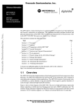
Chapter Three
Operation Panel
The turning CNC system(system or CNC) uses the aluminum alloy three-D operation panel and its
appearance is as follows:
3.1
LCD Display
LCD display: CNC man-machine dialogue interface. Resolution 480×234 lattice TFT color LCD
display.
3.2
LED Status Indicator
LED indicates that the current working state of the system. There are 16 function keys with LED
indicators, the function executed by the corresponding key is valid when LED is ON, and it is invalid
when LED is OFF.
3.3
Keyboard
Based on GB/T 3168-1993 Numerical Control of Machine-Symbol, the system sets the following
symbol function keys which complete the corresponding functions when they are pressed as follows:
3.3.1
Character keys
Character keys include all required valid digit, letter, mathematic symbol and logic symbol.
In EDIT working mode, each letter key can switch into 2 or 3 letter keys; in other working mode, each
6
Operation
Chapter Three
System Operation Panel
letter key only expresses one letter key. (For example, I and I are on one key, the operator directly
press the key when “I” or “P” is required, and the system automatically indentifies other letters.)
Digit key: input all kind of data (0~9);
Letter key: input field, address, English letter;
Symbol key: +, -, *, /, minus sign, decimal and so on;
Logic key: >, =, <, and, or, ()and so on.
3.3.2
Working mode selection key
Marking with the symbols and characters, the working mode selection keys are pressed to
complete the corresponding function, and their definitions are as follows:
: select EDIT working mode
: select JOG working mode
: select AUTO working mode
: select PARAMETER working mode
: select OFFSET working mode
: select DIAGNOSIS working mode
3.3.3
Function keys
Press function keys with the visualization symbol and letter to complete the corresponding functions
and each symbol definition is as follows:
INCREASING RAPID OVERRIDE
Increase rapid traverse override in JOG working mode
and G00 rapid traverse override in AUTO working mode.
REDUCING RAPID OVERRIDE: Reduce rapid traverse override in JOG working mode and
G00 rapid traverse override in AUTO working mode.
INCREASING FEEDRATE OVERRIDE: Increase feedrate override in JOG working mode and
G01 feedrate override in AUTO working mode.
REDUCING FEEDATE OVERRIDE: Reduce feedrate override in JOG working mode and
7
GSK928TEa Turning CNC System User Manual
G01 feedrate override in AUTO working mode.
X PROGRAM REFERENCE POINT(PROGRAM ZERO) RETURN : It is valid in JOG /AUTO
working mode. (program zero is called program reference point in the user manual.)
Z PROGRAM REFERENCE POINT (PROGRAM ZERO) RETURN : It is valid in JOG /AUTO
working mode.
X MACHINE ZERO (MACHINE ZERO) RETURN : It is valid in JOG /AUTO working mode.
(machine zero is called machine reference point in the user manual.)
Z or Y MACHINE ZERO(MACHINE REFERENCE POINT) RETURN: It is valid in JOG
/AUTO working mode.
DRY RUN: In AUTO working mode, whether M, S, T are valid is determined by the
parameter (bit parameter P401_d7), each axis coordinates automatically recover to the
previous ones before the system enters the DRY RUN working mode.
SINGLE BLOCK: A single block runs in AUTO working mode. It is hp function in other
working modes.
3.3.4
Cycle start and cycle pause (feed hold)key
Start and pause programs in AUTO working mode and each key symbol definition is as follows:
CYCLE START: Start to run programs in AUTO working mode; move coordinate axis in
JOG working mode.
CYCLE PAUSE (FEED HOLD ): pause the running in JOG or AUTO working mode; hp
function in other working modes.
【Note】
There is “hp(help) at top right on some keys, and there are 7 help keys hp0~hp6;hp is valid
when the main key is invalid in different working modes.
3.3.5
Manual axis control key
Manual key symbol definitions in JOG working mode are as follows:
X axis moves negatively in JOG working mode.
X axis moves positively in JOG working mode.
8
Operation
Chapter Three
System Operation Panel
Z or Y moves negatively in JOG working mode.
Z or Y moves positively in JOG working mode.
RAPID TRAVERSE/FEED
Switching rapid traverse and feed in JOG working mode.
JOG STEP Selecting each step width or MPG feed in STEP/ MPG(Handwheel) working
mode; hp function in other working modes.
MPG(Handwheel)
MPG control selection and axis selection in JOG working mode; hp
function in other working modes.
Z/Y selection in JOG working mode; hp function in other working modes.
STEP/JOG mode
3.3.6
Switch STEP/JOG mode in JOG working mode.
Manual auxiliary function key
The following press keys are used to controlling and completing all miscellaneous function of the
machine and each key symbol definition is as follows:
Spindle rotation (CW)
Spindle stop
Spindle rotates clockwise.
Spindle stops.
Spindle rotation (CCW)
Spindle rotates counterclockwise.
Cooling control
Switch cooling ON/OFF.
Spindle gear shifting
Select the speed of each gear when the machine is equipped
with multi-gear (up to 16 gears) spindle motor and control
loops.
Tool change
Select the next tool number neighboring to the current one.
9
GSK928TEa Turning CNC System User Manual
3.3.7
Edit keys
Press key
Name
Function explanation
ENTER key
Press it after the corresponding operation is performed.
INPUT key
Input the required content.
ALTER key
Switch character insert/alter state in EDIT working mode;
Special definition in other working modes.
Delete digit, letter, block or whole program in EDIT working
DELETE key
mode;
Special definition in other working modes.
ESCAPE
key
HOME key
END key
Cancel the current input data or escape from the working
state;
escape from the current operation or setting.
“DRY RUN” in AUTO working mode;
Cursor moving the end of the line in EDIT working mode.
“STEP” in JOG working mode;
Cursor moving the end of the line in EDIT working mode.
“SINGLE/CONTINUOUS”
SINGLE
BLOCK key
executing
programs
in
AUTO
working mode;
“SINGLE/CONTINUOUS” analog executing programs in
AUTO working mode;
hp function in other working modes.
Cursor
h p0
hp 1
movement
key
10
Control cursor movement in EDIT/PARAMETER/OFFSET
working mode;
Hp function or other special definitions in other working
modes.
PAGE
Display page up/down in EDIT/PARAMETER/OFFSET;
UP/DOWN
Special definition in JOG /AUTO working mode.
Operation
Chapter Four
Chapter Four
System Operation
System Operation
This chapter introduces operations and notes of the system. Please read carefully before operation.
4.1 System ON/OFF, Initial State, Modal, and Safe Protection
4.1.1
Power on
There is not a power switch on the operation panel of the system. The operator installs it according to
the different machine to avoid bad effects to CNC system owing to the impaction of power supply.
Check before the system is turned on:
1) Ensure the machine state is normal;
2)
Ensure the voltage meets the requirements;
3)
Ensure the wiring is correct and firm.
The system is turned on as follows:
1) The master power switch of machine is turned on.
Switch on the power switch of the CNC system, and the system displays as Fig. 4-1. Press
, and the system enters into EDIT working mode.
any keys except for
Fig. 4-1
System initialization display window
2) The system orderly completes the following work after power-on:
z
The system controls the program loading.
z
The system automatically check itself and executes the initialization.
z
The system loads and checks parameters.
z
I/O interface initialization.
z
The system loads and checks the operator programs.
【Note】
1)Must not press any keys on the system panel when the system is turned on, press
RESET key when the system enters the press key test window at the moment.
4.1.2
Power off
The system is turned off as follows:
11
GSK928TEa Turning CNC System User Manual
1) The power switch of the CNC is turned off.
2) The power switch of the machine is turned off.
Check before the system is turned off:
1) X, Z, Y are in the stop state;
2) Miscellaneous function(spindle, cooling) OFF;
3) Turn off the power supply.
【Note】
1) The system should be checked itself and initialized when it is turned on firstly( it is
completed by the machine manufacturer, and the operator cannot execute the operation,
otherwise, the parameter set by the machine manufacture will lose).
2) Operations related to turn off the machine power supply are referred to the operator manual
machine manufacturer.
4.1.3
4.1.3.1
System, program initial and modal
Initial and modal
The initial mode of the system is defined to be a special initial state of all functions set by itself when
the system is turned on; all auxiliary functions do not execute the actual output.
The modal of the system is defined to be their kept states after the system executes all functions.
Initial mode and modal of the system:
System state
Machine coordinate system
of the system
Tool nose coordinate system
of the system
Cutting feedrate:F
Conversion spindle speed:S
Spindle gear
MANUAL slow feed/rapid feed state
Feedrate override
Rapid override
Spindle state
Cooling state
Chuck state
Lubricating state
T number state
Tailstock state
Set spindle speed/position mode
4.1.3.2
Initial mode
Keep last power-on state
Modal
Keep till being changed
Keep last power-on state
Keep till being changed
In Auto mode:30mm/min
In JOG mode: Keep last power-on state
Keep last power-on state
Shifting gear spindle gear:S0
Conversion spindle gear:M41
Slow feed
Keep last power-on state
Keep last power-on state
M05 spindle stop
M09 cooling OFF
M11 chuck release
M33 lubricating OFF
Keep last power-on state
M79 tailstock run-out state
M48
Keep till being changed
Keep till being changed
Keep till being changed
Keep till being changed
Keep till being changed
Keep till being changed
Keep till being changed
Keep till being changed
Keep till being changed
Keep till being changed
Keep till being changed
Keep till being changed
Keep till being changed
Initial mode and modal of program
The initial mode is the automatic initialization setting state before the system executes the machining
program; i.e. the initial default state of the default programming word and speed word.
Program initialization state of the system:
G command:G00, G40, G97, G98;
Cutting speed:30mm/min;
Miscellaneous function: current state;
System coordinates: current coordinates are those of the last automatic executing
program or manual operation
12
Operation
Chapter Four
System Operation
G modal is always valid till it is changed by other modal commands in the same group after the
word is set. After the modal meaning is set, the G command may not be input again when the
same function is used in the later block.
There are four groups of G command with modal characteristics, and there is only one command
in the modal state:
Group 1:G00, G01, G02, G03, G05; (initial mode:G00 );
Group 2:G40, G41, G42;
(initial mode:G40 );
Group 3:G96, G97;
(initial mode:G97 );
Group 4:G98, G99;
(initial mode:G98
F30 );
The command without modal characteristics has effect in the block and must be defined to use every
time.
【Note】
In AUTO working mode, the system automatically recovers to the program initial mode when it
executes the first command of workpiece program or executes the first block command after M20, or
selects the middle block as the first command.
4.1.4
Safe protection
The CNC system set a perfect protection measure to prevent the operator from danger and the
machine from being damaged.
4.1.4.1
Hardware limit protection
The system can check the travel limit switch installed on the machined. When the machine slide
moves to press the travel limit switch, the system stops feeding instead of closing other
miscellaneous functions, and the program stops running and the system displays the hardware limit
alarm information of corresponding axis.
After the travel limit switch alarms, the system can select JOG working mode, the manual feed key
which is reverse to the limit direction is pressed, i.e. the system escapes the travel limit and the travel
limit switch alarm automatically disappears on the screen.
【Explanation】
1) X, Y, Z positive limit check shares one pin LT+, and their negative limit check shares one pin
LT-; when the positive limit alarms, all axes can not move positively but move negatively; and
vice versa.
2) When the travel limit switch runs across the limit block, the limit signal appears; the valid
length of limit block signal is more than 30mm or more to avoid rush out the valid area of the
signal.
3) When the parameter is set to “limit emergency stop” mode (bit parameter P402_d7=1), and
the system runs across the limit block, there may be great deviation between the coordinates
displayed by the system and the actual position.
13
GSK928TEa Turning CNC System User Manual
【Relative parameters】
Bit parameters: P402_d7, P404_d6, P404_d1.
Bit parameter P402_d7 sets the hardware limit alarm mode;
Bit parameter P402_d6 sets whether the hardware limit alarm checks;
Bit parameter P402_d1 sets the hardware limit alarm level of each axis;
When P404_d1=1 is high level alarm, the positive limit switch +X, +Y, +Z of each axis are normally
closed contact, are connected to X/Z/Y positive limit input interface LT+(they are open and the system
alarms) in serial; the negative limit switch -X, -Y, -Z of each axis are normally closed contact, are
connected to X/Z/Y negative limit input interface LT+(it is off and the system alarms) in serial; it is
suggested that the operator should select in prior the hardware limit to the normally closed contact of
each axis as follows:
When P404_d1=0 is low level alarm, the positive limit switch +X, +Y, +Z of each axis are normally
open contact, are connected to X/Z/Y positive limit input interface LT-(they are closed and the system
alarms) in serial; the negative limit switch -X, -Y, -Z of each axis are normally open contact, are
connected to X/Z/Y negative limit input interface LT-(it is off and the system alarms) in serial; it is
suggested that the operator should select in prior the hardware limit to the normally closed contact of
each axis as follows:
4.1.4.2
Software limit safe protection
1) Mechanical software limit safe protection
The mechanical software limit safe protection is to limit machine coordinate motion range to
avoid slide to exceed the motion range. The mechanical software limit alarms when the machine
position(machine coordinates) exceeds the range.
Releasing overtravel alarm methods: reversely movement in JOG working mode (negatively
moves for positive overtravel; positively moves for negative overtravel).
2) Tool nose software limit safe protection
The tool nose software limit safe protection is to limit tool nose coordinate motion range to avoid
the tool nose to exceed the motion range. The tool nose software limit alarms when the machine
position(tool nose coordinates) exceeds the range.
Releasing overtravel alarm methods: reversely movement in JOG working mode(negatively
moves for positive overtravel; positively moves for negative overtravel).
14
Operation
Chapter Four
System Operation
【Explanation】
1) The coordinate axis decelerates to stop when the coordinates exceed the software limit range
during the motion.
【Relative parameters】
P009, P010: max. travel of Z positive, negative tool nose software limit; P011, P012: max. travel of X
positive, negative tool nose software limit;
P013, P014: max. travel of Y positive, negative too nose software limit; P015, P016: max. travel of Z
positive, negative mechanical software limit;
P009, P010: max. travel of Z positive, negative mechanical software limit; P009, P010: max. travel of
Y positive, negative mechanical software limit;
Bit parameter P404_d4, P404_d3 separately sets whether the mechanical, tool nose software limit
alarm are valid.
4.1.4.3
Emergency stop alarm(emergently stopping the system)
When there is the external emergency stop input terminal ESP in the system input interface, the
operator should connect the emergency stop button Normally closed contact on the machine panel
with the emergency stop input terminal. Press Emergency stop button and the system enters the
emergency stop state. The system stops all feed, the spindle, the cooling switching output is valid and
the system displays “Emergency stop alarm”.
After the emergency stop condition is released, the operator should rotate the emergency stop button
clockwise based on the up arrow, the button automatically releases to cancel the emergency stop
signal.
When the system is in the emergency stop alarm state and the external emergency stop signal is
cancelled, the “RESET” key is pressed to escape the emergency stop state to return the previous
working mode.
When the system is in the emergency stop alarm state and the external emergency stop signal is not
cancelled, the operation is forbidden in JOG, AUTO and DIAGNOSIS working mode; is permitted in
EDIT, PARAMETER, OFFSET working mode.
Press RESET to clear the emergency stop alarm window in EDIT, PARAMETER and OFFSET
working mode, and the system permits the operation.
There is the Emergency stop in the movement, there may be great deviation between the coordinates
displayed the system and the actual position, and the operator must correct the machine coordinates.
When the emergency stop button is pressed and the emergency stop alarm is released, the system
state is as follows:
1) When the system is in DRY RUN state in Auto working mode, it escapes the state.
2) When the system is in rapid state in JOG working mode, the system automatically switches
into the feed state.
15
GSK928TEa Turning CNC System User Manual
3) The interface output signals of the chuck, tailstock, and machine in the electricity power-on
delay do not change; the system sets the internal memory state to M11, M79. After the
emergency stop is released, the system chuck and tailstock state is separate M10, M78 after
the chuck or the tailstock pedal switch is pressed firstly.
4) Besides the above functions, other function states are initial mode; the system stops all feed,
the spindle, the cooling and other switching controls set the output to be invalid.
【Relative parameters】
The external emergency stop signal function is valid when P404_d7 is set to 0.
The external emergency stop signal function is invalid when P404_d7 is set to 1.
The parameter is for debugging the system, and must be set to valid in the power-on state,
otherwise, it cannot have the protective effect.
4.1.4.4
Drive unit alarm
When the system is connected with the alarm output signal of a drive unit and appears Drive unit
alarms, the system automatically closes all feed and prompts Z/X/Y drive unit alarms. All axes
immediately stop motion, and the program stops running. At the moment, check the drive unit and
relative device to troubleshooting and the system is turned on again.
When there is the alarm in the course of motion, there may be great deviation between the
coordinates displayed the system and the actual position, and the operator must correct the machine
coordinates.
In JOG working mode, the system prohibits all axes moving when there is the alarm.
In AUTO working mode, the system prohibits the program starting run when there is the alarm.
【Relative parameters】
The drive unit alarm checks when P404_d5 is set to 0.
P405_d4, P405_d3, P405_d2 separately sets alarm level of Z, X, Y drive unit.
4.1.4.5
Other alarms
When the system appears other alarms, Chinese characters prompts, at the moment, the operator
can perform the troubleshooting based on PROGRAMMING, Chapter 8 Alarm Message.
4.1.4.6
Switching off power supply
The machine power supply is switched off immediately to avoid the accidence in the danger or other
emergency cases when the machine is running.
Note: When the coordinate axis is moving and the power supply is switched off, after the machine is
switched on again, there may be great deviation between the displayed coordinates and the
actual position, and so the operator must execute the machine zero return or other ways to
regulate the machine coordinates to ensure that the displayed coordinates are the same those
of the actual.
16
Operation
4.1.4.7
Chapter Four
System Operation
Reset operation
When the system outputs abnormally and the coordinate axis moves abnormally, the operator should
press
to make the system be the reset state as follows:
1) All axis motions decelerate to stop;
2) S function output is invalid;
3) whether M function output is valid is set by P403_d2.
4) The automatic run ends, the modal function and state keep.
【Relative parameters】
P403_d2=0: the system closes M03, M04, M08, M32 output signals when the reset key is
pressed.
P403_d2=1: the system does not close M03, M04, M08, M32 output signals when the reset key
is pressed.
4.2 CNC Working Mode Selection
The system uses the working mode key to directly select the all working modes. All working modes
can direct switch to get the simple and convenient operations.
The display is as Fig. 4-1 after the system is turned on, and the display state keeps till the other key is
pressed to enter the EDIT working mode.
4.3
EDIT Working Mode
EDIT working mode: it is the working mode to execute the part program by the operation panel. There
is the corresponding intelligent prompt message for each operation. At the same time, the operator
can press the prompt key- hp2 at the top right to learn the operation key list in EDIT working mode.
The relative setting or operation key format and sample descriptions in the user manual are as
follows: meanings and uses of all required functions are described at the beginning of the
corresponding chapter; all required letter and digit keys are expressed with underlines; the system
prompt messages are expressed with borders.
In executing some setting or input or man-machine dialogue, press ESC key to escape the current
operation before
◆
key is not pressed.
Main functions in Edit mode include:
☆ select, create, rename, copy and delete part programs;
☆ input, insert, modify and delete the content of the selected part program;
17
GSK928TEa Turning CNC System User Manual
☆ transmit part programs between U disc and the system by the USB interface;
☆ transmit part program between the external PC and the system by RS232 communication
interface;
☆ transmit part program in two systems by RS232 communication interface;
☆ compile and save program;
program motion path drawing analog;
☆input variable and macro character string.
Press
to enter the EDIT working mode. The EDIT working mode includes two main
window: program catalog search window and program edit window. The program catalog search
window is as Fig. 4-3:
Current program No.020
EDIT
Program length 1KB
Name size remark
Name size remark
Middle
Middle top
% 000
1KB
G00
% 001
1KB
G0
X115
KB
G50
X150
1KB
G00
KB
G50
% 0022
% 020
% 0302
Middle bottom
Upper top
X0
[press key prompt]
[U] enter USB communication
X300
[R] enter RS232 communication
Pop-up window
X250
Program remaining space: 792KB
Program count:45
Lower bottom
EDIT
JOG
AUTO
Fig. 4-3
PAR
OFT
DGN
program catalog search
◆ Display content in window area:
Upper top: program number and capacity of current program(program length), the system
function operation method prompt key hp2;
Middle top: orderly arrange program name, capacity, remark;
Middle: display program name, capacity and remark;
Middle bottom: operation prompt message;
Lower bottom: display current stored part program quantity (up to 255) and surplus stored space;
Pop-up window: display operation prompt message.
【Note】
Press hp2 key, and the system prompts “ Program catalog window message prompt”, introducing
the used press key functions.
4.3.1
Part program catalog search
Program catalog search window displays the current stored program quantity, and all programs sorts
as follows:
1)name: program number from top to bottom, from left to right;
2)size: program stored space from top to bottom, form left to right;
18
Operation
Chapter Four
System Operation
3)remark: the first 12 characters of the first line of the program from top to bottom, from left to
right;
4)the last: input time sequence from top to bottom, from left to right.
,
Press
and
,
program on each window; press
,
4.3.2
, the system searches all part programs, displaying 12
to the first page of program,
to the last. Press
to sort all programs according to their name, size, remark and last distribution.
Selecting, creating, deleting, renaming and copying a part program
Select, create, delete, rename and copy part programs
【Note】
1) The system executes most %000~%254 programs, 255 program names. The system
prompts E160 input program error when the executed program name is more than 254.
2) There is no part program or the system is not used firstly, the system automatically creates
and selects %000 program as the current program. When there are programs, the system
sorts the program according to part program quantity and program names in the last
power-off.
3) The system supports many input, the leading zero can not be input. Example, inputting
%003 program. Press INPUT, input 0 0 3 ; also input
4.3.2.1
0 3 ; or input 3.
Selecting and creating a part program
The operations to select a part program or create a new program are as follows:
①
Press INPUT key in EDIT working mode;
②
Input the required program number by the board key, or input a program number which is
not in the program catalog list as the new program number;
③
Press ENTER key;
④
Select or create a part program, display the content of the part program, and the system
enters the program edit window.
【Note】
1) When a program is selected, it is changed by the above steps; it cannot be changed once it is
confirmed.
2) there is no the selected program number in the input part program catalog, creating a
program is taken as the current program.
【Example】
Example 1:there is no %20 part program in the part program catalog, creating it is as follows:
Press keys to input: INPUT
2
0 ENTER. The new program %020 has been
19
GSK928TEa Turning CNC System User Manual
created and the system enters %020 program edit window.
Example 2:there is no %20 part program in the part program catalog, creating it is as follows:
Press keys to input: INPUT
1
0 ENTER. The new program %001 has been
created and the system enters %001 program edit window.
4.3.2.2
Delete a part program
Delete a part program is as follows:
① Press INPUT key in Edit working mode;
② Input the required program number to delete by the key board;
③ Press DELETE key, the system prompts: Enter-confirm the deletion Esc-escape the deletion .
④ Press ENTER to delete the part program which program number is input. Press ESC not to
execute the deletion operation and return to EDIT working mode.
【Note】
1)The system prompts E100 does not exist when there is no the program which is to be
deleted;
2)When the program which is to delete exists: when it is not the current program, the system
deletes the program from the program list; when it is the current program, the system deletes
the program from the program list, and searches the program which program number is the
smallest to be the current program; when there is no programs, the system creates one
program number 000 as the current program.
【Example】
Example: delete %003 operation is as follows:
Input by the press key: INPUT 3
4.3.2.3
DELETE
ENTER.
Deleting all part programs
Clear the program area in the program catalog search window, and all programs in the system are
deleted as follows:
① Press INPUT in the part program catalog search state;
② Input
,
by the key board;
,
;
③ Press DELETE , the system prompts: Enter-delete all programs Esc-escape the deletion .
④ Press ENTER to delete all part programs; press ESC not to execute the deletion operation
and return EDIT working mode.
【Note】
The system creates a program number 000 as the current program after all part programs are
deleted.
20
Operation
4.3.2.4
Chapter Four
System Operation
Renaming a part program
The program name of the current program is renamed as another new one. The new is taken as the
current program is as follows:
①
Press INPUT key;
②
Input the program number which is not in the program list, press ALTER and the current
program number is rewritten to the input program number.
【Note】
When the input program exists, the system prompts E166 required renaming program has
existed.
【Example】
Example: the current program %000 is renamed to %005 as follows:
Press key input: INPUT 5
4.3.2.5
RENAME . And the renaming is completed.
Copying a part program
Copy the current program content to another one new and the new becomes the current program as
follows:
①
Press INPUT key;
②
Inputting the program name which is not in the program list, press INPUT key and the
current program content is copied to the new program. The new program is taken the
current one.
【Note】
When the input program name exists, the system prompts E161 copying program exists and
waits the prompt losing to input a new one.
【Example】
Example: copy the current program %000 to %005 as follows:
Press key input: INPUT 5
4.3.3
INPUT. The copy operation is completed.
Part program communication
The communication of part programming includes the sending and receiving the part program. The
sending is divided into: the system outputs to PC(CNC→PC), one system outputs to another one
(CNC→CNC), and the system outputs to U disc (CNC→USB);
Press hp6 in the program catalog search window, the system prompts the part program
communication window.
21
GSK928TEa Turning CNC System User Manual
4.3.3.1
Sending part programs(CNC→PC, CNC→USB, CNC→CNC)
Method 1:RS232 serial communication;
1) Before file transmission, the system sets P414_d7, P414_d6 communication baud rate. The
communication baud rate is determined by the sending setting. The setting range: 9600,
19200, 38400(unit:bps). Setting communication baud rate is referred to OPERATION, 4.6
Parameter Working mode.
2) Part programs stored in the system are output to another one as follows:
①
connect with communication cable in power-off;
②
press key to input:hp6 → R →
③
select the required program to send according to the system hp2 help message;
④
press ENTER to send;
⑤
the external PC or another system are in the receiving mode;(refer to OPERATION,
hp2
;
Chapter 5 RS232 and USB System Communication)
the system outputs the selected programs and displays the sending process till the
⑥
sending is completed; when the selected programs are so many, the system sends the
programs from the small to the big of their program number till the sending is completed;
press ESC to interrupt the sending in the course of sending.
⑦
Method 2:USB communication;
1) After entering USB communication mode, the system firstly checks whether U disc has
inserted, if not, it displays the prompt box Have not inserted USB. If the disc has inserted, it
has “C928PRO” file, and USB file catalog lists “CNCxxx.TXT”. when U disc has “C928PRO”
where has no“CNCxxx.TXT”, USB catalog box displays the blank. When U disc has no
“C928PRO”, USB file catalog box is not displayed.
2) Output the part program stored the system to U disc as follows:
①
insert U disc in the system USB;
②
the system automatically open U file catalog(create a file in the U disc: C928PRO,file
format CNCxxx.TXT). The system creates “C928PRO” when there is no “C928PRO” in the
U disc root catalog.
③
Press key to input :hp6 → U ;
④
Select the required programs to send according to the system hp2 help message.
⑤
Press ENTER to send and the system prompts to select the sending mode;
⑥
the system outputs the selected programs based on the selected sending mode and
displays the sending process till the sending is completed;
⑦
4.3.3.2
select ESC to escape U disc.
Receiving part programs(PC→CNC, USB→CNC, CNC→CNC)
Method 1: RS232 serial communication;
1) Set the communication software baud and communication terminals (Setting communication
22
Operation
Chapter Four
System Operation
baud rate is referred to OPERATION, 4.6 Parameter Working mode).
2) input the part program stored in the external PC to the system or transmit part programs
between two systems as follows:
①
connect with communication cable in power-off;
②
press key to input:hp6 → R →
③
select the receiving mode according to the system prompt;
④
programs in the external PC or another system are input to the CNC system;
⑤
the system selects the receiving mode and inputs the programs, displays the receiving
edit ;
process till the receiving is completed;
⑥
press ESC to interrupt the receiving in the course of receiving.
Method 2:USB communication;
1) After entering USB communication mode, the system firstly checks U disc, and opens
“C928PRO” existed in the U disc and lists “CNCxxx.TXT” file.
2) Output part program stored in U disc to the CNC system as follows:
①
insert U disc in the system USB interface;
②
press key to input:hp6 → U → EDIT;
③
the system automatically opens U disc file catalog;
④
select the required programs to receive according to the system hp2 help message;
⑤
press ENTER to receive and select the sending mode according to the system prompt;
⑥
input the programs according the selected receiving mode, display the receiving process
till the receiving is completed;
select ESC to escape the U disc.
⑦
【Note】
1) When there is a program which name is the same the sent program, the operator replaces the
existed with the sent, the sent program replaces the previous once the replacing is executed.
4.3.3.3
TXT part program standard format in PC
Use TXT, LST text to edit part program in PC, but the file name must be compiled based on the
standard format required by the system to be sent to the system as follow:
1) Name the file name of the part program to TXT or LST suffix, such as “CNC008.TXT”; it is
suggested that the operator uses TXT suffix to conveniently execute part programs on the
PC.
2) The first line of TXT file content must specify the program number, its format is “% XXX”, i.e.
percent sign follows the digit 1, 2 or 3, its range is 0~254, and the first line cannot have other
content. Its range must be 0~254 because the program number created and stored by the
system is 0~254, otherwise, the system cannot receive the programs and prompts the
corresponding mistaken message. The program numbers received by the CNC are
determined by two methods (USB and RS232):
◆ In RS232 communication, the program names are taken the program number of the
23
GSK928TEa Turning CNC System User Manual
first line as the standard; i.e. the character string XXX digit of “%XXX” in the first line
sent by PC.
◆
The program number sent by the system USB is CNCxxx.TXT xxx digit in“C928PRO”
file in the U disc root catalog.
Note: in USB communication, the character string XXX digit of %XXX” in the first line should be
the same that of xxx digit of CNCxxx.TXT. When they are different, the xxx digit of CNCxxx.TXT is
taken as the standard.
3) The blocks start from the second block. The block must meet its format. Each block cannot
exceed 250 characters, ends with the ENTER key, otherwise, the system prompts the error:
Program line too long in receiving programs.
4) The annotation area has Chinese annotation in the block.
5) Max. TXT file length cannot exceed the program stored space limit of the system.
Part program communication standard format in PC:
TXT file format
%099
N0000 G50 X100 Z100 ; setting coordinate system
N0010 G00 X20 Z90
; rapidly positioning
G01 X10 Z80
; linearly cutting
……
/N0250 G02 X30 Z20 R5 ;arc cutting
N0260 ;T22
;tool change
N0262 M05
N0270 G04 D8
……
M20
4.3.4
1.
2.
3.
4.
5.
6.
Explanation
There must be program name %099 when
the system receives programs; the first line
must the 3-digit 0~254+。
“N****” are the blocks with the line number,
and others are the blocks without the line
numbers;
The hone of each line must be blank;
there is a space between the line number
and the command for the program with the
line number;
/ block skip;
;the following is the annotation.
Part program content input and edit
Each input part program consists of many block, and each block is composed of block number,
command and data. The program format must meet the general programming rules, and there is no
prompt in program compiling, and the alarm prompts are referred to PROGRAMMING, Chapter 8
Alarm Message. The qualified parts can be machined only according to the technology requirements
and orderly input correct program contents.
The edit mode of the system is full screen. The program edit window is displayed as Fig. 4-4:
【EDIT】
Middle
%001
N0000 G0 X100
N0010 X0
N0020 X100
N0030 X0
N0040 G1 X100
N0050 X0
N0060 X100
N0070 X0
N0080 X100
N0090 X0
N0100 G1 Z100
N0120 M20
RW 8
F80
Ln 3
Lines 11
SIZE 1KB
Current editing program
compiled successfully
Fig. 4-4 program edit
24
hp2
is
Top
Pop-up
window
Operation
Chapter Four
System Operation
◆Display content in window area:
Upper top: program number, program capacity(program length) and program line quantity of
current program, edit cursor line and row (prompt symbol of current editable character
position), and the system function operation prompt key hp2;
Middle: program edit window;
Pop-up window: display operation prompt message.
【Note】
1.
Press hp2, the system prompts “Program edit help message prompt”, introducing
all help key explanation.
2.
When P416_d0 is set to 1, the system forbids pressing key to edit and modify
programs, and prompts the alarm E174:machining programs are locked and are
forbidden to modify; when the system edits and modifies the programs, P416_d0
should be set to 0.
Edit key meanings and use in program edit window:
,
1)
cursor UP, DOWN move key:
Press the move key every time, and the cursor moves up(down) till the top (the bottom)
line. Keep pressing the moving key and the cursor continuously moves up(down) till the
first(last) line or the move key is releases. In the character string search function(hp5), the
operator can search the required character string up and down.
,
2)
cursor LEFT, RIGHT movement key:
Press the move key every time, and the cursor moves left(right) one character. Keep
pressing the moving key and the cursor continuously moves left(right) till the first(last)
character or the move key is releases.
3)
Home key: the cursor rapidly moves to the home or the first field head of the line.
Press continuously the head key, and the cursor switches between the head and the first
field of the line. The compound of the head key and the deletion key can delete the current
line.
End key: the cursor rapidly moves to the end of the line.
4)
insert/alter:
Changing edit input mode: switch the insert and the alter after pressing it once. The cursor
also changes correspondingly and the insert mode cursor flashes to be one horizontal line,
and the alter mode cursor flashes to be the high light square.
5)
input key:
The program edit state is switched into the program catalog search state, and the system
25
GSK928TEa Turning CNC System User Manual
prompts Input program number: .
Page Up, Page Down:
6)
Paging to display the program content. In hp5, the cursor directly moves the
home/the end window; in hp4, the system can zoom out/down the graph.
7)
Enter key: The cursor moves to the next block down.
8)
delete key: Delete all blocks or characters in the block.
9)
hp2 key:program edit help message prompt; switch Single/Continuous mode in
motion path analog drawing.
hp3 key:current program compiling and analog drawing current program graph.
10)
hp4 key:MPG controls the cursor moving.
hp5 key:execute No. 253 or No. 254 program, the system command help and part
program character string search.
hp6 key:prompt the displayed macro character string list.
Multi-function definition key input must obey the following rules:
1)When the first letter is capital in the line, the first key value is prior; when it is the lowercase,
the 3rd or 2nd key value is prior.
2)The system automatically creates the blank space when the letter or character following the
digit (0~9)is input.
3)The cursor stays the position where the input is convenient after the character string is input.
Multi-function definition key value list:
Panel display
>
st
key
1
value
2nd
key
value
G
r
M
H
X
Z
st
key
1
value
2nd
key
value
3rd
key
value
F
N
()
=
I
P
J
>
K
Blank
space
Q
<
D
V
and
R
Y
or
Panel display
( )
and
<
S
26
3rd
key
value
if
or
Operation
then
else
/
;
4.3.4.1
Chapter Four
T
L
then
U
E
else
W
/
;
*
System Operation
.
*
-
+
Inputting program content
Note: P333 is set to 10 (the system automatically creates the block number, and the following
is the same).
In program edit window, inputting the part program content is as follows:
①
create a new program according to the operations of creating new part program;
②
input one line content after the block N0000
③
press ENTER key after inputting one line programs to end the line input;
④
the system automatically creates the next block number and continuously input the program
is displayed;
content;
⑤
press ESC to complete the program content input after the last line programs are input.
【Note】
1) The first row of every line only displays the blank space;
2) Each block only displays 60 characters, and only the first 60 characters are displayed when
there are more than 60 characters, the operator can press
to left move one
character.
3) The serial number of the first row blank is 0, the last is 251, and the system only displays the
cursor instead of the character; there are up to 250 characters in the edit line; i. e. the first
blank bit +250 characters+ the last cursor bit character=252.
4.3.4.2
Inserting program line
Insert one or many program line between two program lines or in the front of the current block as
follows:
①
Move the cursor to the first block end or the last block home of the two blocks;
②
Press ENTER, and the system automatically creates a new block number between the
current block and the next (the serial number increment is P333 parameter 1/4 integer, the
next block number can be modified when the above the increment is not enough) and
remains a blank line.
③
Input the required block content;
④
After all content is input and many line are required to insert, ENTER is pressed, which is not
done when one line is required to insert.
【Example】
Example: insert a new block
M3
between N0020
and
N0030 as follows:
27
GSK928TEa Turning CNC System User Manual
4.3.4.3
Deleting a block
Delete all content in one line as follows:
①
move the cursor the hone of the required line;
②
press DELETE;
③
delete all content of the selected line.
4.3.4.4
Inserting a character in a block
Insert a character in one block as follows:
①
Press ALTER, switch the input mode to insert mode, i.e. the cursor is displayed to the down
horizontal line;
②
Move the cursor to the character following the required insert position;
③
Input the required insert content;
④
Insert the input content before the character pointed by the cursor.
【Note】
The CNC system requires there is a blank space between fields in the program line. In editing
program, the system can automatically judge and create a blank space, but cannot automatically
judge in the insert operation, and at the moment, the operator should input a blank to get the
complete program.
【Example】
Example: insert
1 between
X
and
0 in N0020
G0
X0.0
The cursor moves the under 0 following X input 1 , displaying
4.3.4.5
Z0.0. As follows:
N0020
G0
X10.0
Z0.0
Deleting a character in a block
Delete the content which is not needed as follows:
①
Move the cursor to the character position which is needed to delete;
②
Press DELETE to delete the character.
4.3.4.6
Modifying a block content
Modify the content of the block into the new, which can be complete according the input
mode(insert/alter).
In INSERT mode, use the insert and deletion as follows:
①
Move the cursor the character which needs to be modified;
②
Input the new content;
③
Press DELETE to delete the required content.
In REWRITE mode, directly modify the content as follows:
①
Press ALTER; the cursor switches into the alter mode(the character position pointed by the
cursor is high light square);
28
②
Move the cursor to the character which needs to be modified;
③
Input the new content. The cursor points the next character.
Operation
Chapter Four
System Operation
【Example】
Example: alter X in N0020
G0
X0.0
Z0.0 into
U
as follows:
Switch the input mode into ALTER mode, move the cursor to the down of X and input U .
Alter to N0020
4.3.4.7
G0
U 0.0
Z0.0 .
Inserting a macro character string
Insert macro character string content in program edit window as follows:
①
press hp6 and the system displays macro character string list;
②
select the required input content according to the press key;
③
list: the front of the colon is the press key value, the following is the inserted character string
content.
【Example】
Example: press hp6 and then
G , the program content input: r = r * r / r , the cursor stops the
following of r.
【Note】
Concrete variable and statement programming are referred to PROGRAMMING, Chapter 9
Statement Programming.
4.3.4.8
Program stored space
For No. 0~252, No. 254 program, the system provides 800K stored space, and so the single
program can be up to 800K. For No. 253 program, the system provides 4m FLASH stored space.
【Explanation】
1)The system displays the program leftover space and prompts the leftover stored space size.
2)When the current edit No. 0~252, No.254 program size are more than all stored space(max.
800K), the programs cannot be saved, and the system prompts the storage space has full:
Overflow in edit area. Delete the old programs when the leftover space is not enough.
3)Max. edit space of No. 253 program is up to 4M, and is only saved to the system FLASH.
4)In saving programs, the program capacity is big and saving the programs need long time, and
the operator needs to wait.
4.3.4.9
No. 253 program operation
Because No. 253 program is up to 4M, its solidifying and read are special as follows:
1) Only be saved to a fixed FLASH;
2) Select No. 253 program, press hp5 and then 4 to save it to the FLASH in program edit
window;
3) Use USB or RS232 to complete the communication.
【Note】
1)No. 253 program cannot automatically save, compile and solidify(FLASH) it after compiling,
otherwise, it cannot be saved.
29
GSK928TEa Turning CNC System User Manual
2)No. 253 program cannot be copied and renamed.
3)In saving No. 253 program, the program capacity is big and saving it needs long time, and the
operator needs to wait.
4.3.4.10
No. 254 program operation
For No. 254 program, press hp5 in program edit window, the system prompts the help message
prompt box how to compile, solidify and read No. 254 as follows:
1)
Press 5
to compile and solidify No. 254 program:
Edit No.254 program. The system alarms when the edit is wrong; the system saves it to the
FLASH area when it is compiled successfully.
2)
Press 4 and read No. 254 program:
Read No. 254 program saved in FLASH area to the edit buffer zone, and update it.
3)
4.3.5
Press ESC to escape the current state.
hp5 function
hp5 help key including the system command help, relative parameter help for arc, line number sort,
character string replacing, cursor positioning and MPG controlling cursor moving and so on.
When the current program is No. 253 or No. 254, hp5 help key adds its operation prompt.
4.3.5.1
Part program command help
In program edit window, press hp5
1
, the system prompts “Command help introduction” window;
the function can search all commands of the system including G, M, S, T, F as follows:
1)G , M , S , T , F separately introduces G, M, S, T, F command.
2)press INPUT and input the command number to search; the system displays the definition, the
function, the format and the explanation of the command number.
【Example】
Example: search G05 command help.
Press :hp5
1
INPUT
G
05
ENTRE, the system displays G05 definition, function,
format and explanation.
4.3.5.2
Relative parameter help for arc
Press hp5 2 in the program edit window, the system prompts “Input relative arc parameters” window;
the function can search arc parameters.
Input [starting point coordinates], [end point coordinates], [circle radius], the system
automatically counts the relative parameters of arc.
【Example】
Starting point A coordinates(60, 10), end point B coordinates (40, 30) as follows:
30
Operation
Chapter Four
System Operation
Z
1
2
[Input relative arc parameters]
[Starting point coordinates] Z: 60
X:
10
[End point coordinates]
X:
30
[Circle radius]
Z: 40
R: 20
Input the above data, and the system automatically counts the following data:
CW circle center 1:
Z: 40
X:10
(Z, X:CW circle 1 coordinates.)
CCW circle center 2:Z: 60
X:30
(Z, X:CCW circle 2 coordinates.)
Starting point->circle center 1: Z: 20
X: 0
(Z, X:Z, X vector of starting point A pointing
to circle center 1.)
Starting point->circle center 1: Z: 20
X: 0
(Z, X:Z, X vector of starting point A pointing
to circle center 1.)
End point->circle center 1:
Z: 0
X:
20
(Z, X:Z, X vector of end point B pointing to
circle center 1.)
Starting point->circle center 1: Z: 0
X: -20
to circle center 2.)
End point->circle center 1: Z: -20
X:
0
(Z, X:Z, X vector of starting point A pointing
(Z, X:Z, X vector of end point B pointing to
circle center 2.)
4.3.5.3
Line number sort
Press hp5 3
in the program edit window, and the system sort again the programs, and the sorted
block number increases in 10 times. (P333 value is set to 10.)
【Note】
1) After sorting the block number again, the program skip error appears when the program skip
command is used in programming.
2) Program sorting function is invalid when P333 is set to 0.
4.3.5.4
Replacing character string
Press hp5 R
in the program edit window, and the system prompts “ Character string replacing”
window; the operator can execute the operation according to the system prompts. All characters
which need to be replaced are replaced from the character where the cursor is to the last character.
31
GSK928TEa Turning CNC System User Manual
4.3.5.5
Cursor position
The system provides the character string search function, i.e position the content needed by the
operator, which is convenient for operator to search the required content. Press hp5, and the system
,
prompts
,
1)Press
2)press
,
, F operation functions as follows:
and the cursor positions to the first page of the current program.
and the cursor positions to the last page of the current program.
3)press F, input the character which is needed to search of the current program, press ENTER,
the cursor positions the character.
4)press
,
to search the character of current program according to the system
prompt. The system prompts Searching is completed and there is no character string when
there is the character which is needed to search of the current program.
4.3.5.6
MPG controlling cursor moving
After the system is connected with MPG, the operator presses MPG , rotates MPG to control the
cursor movement when the MPG key LED is light on the operation panel. Press MPG repeatedly,
MPG operation is invalid when MPG key LED is OFF. The concrete MPG connection is referred to
CONNECTION.
4.3.6
Part program compiling
The system provides hp3 compiling command key to compile part programs, check the syntax error,
logic error of programs and coordinate data overtravel according to part program execution path to
reduce the alarm error in Auto mode and improve the safety of executing part programs.
Press compiling command key and the system orderly checks and compiles part programs from the
first line block, and creates convenient target command according to the execution path. When the
system finds out the mistaken operator programs, it stops the compiling, displaying the mistaken field
position and number in the line of the source program, prompting the operator to modify till the
mistaken is corrected.
4.3.6.1
hp3 compiling command
In program edit window, press hp3 and the system orderly compile the current program. The system
pops up a window『Program alarm』when it finds out a mistaken message. The system displays
Current edited program compiling is completed successfully when all command compiling are
correct.
32
Operation
Chapter Four
System Operation
『Program alarm』message includes as follows:
Error: mistaken command( refer to PROGRAMMING, Chapter 8 Alarm Message according
to the commands);
Line: line where the mistaken block is in the program;
Program: content of mistaken block;
Position: mistaken letter or field of mistaken block.
【Explanation】
1)
Program which is compiled successfully by hp3 can run in AUTO working mode.
2)
The system automatically completes the compile when it switches from EDIT working mode
to other working modes.
3)
Press hp3 to complete compile to appear『Program alarm』, and then press any keys and the
edit cursor automatically points to the mistaken block.
4)
Executing hp3 compiling, the system assumes that the machine coordinate axis takes the
current workpice coordinate position as the starting point, starts the execution from the first
block of the current program. So, for some special programs, each axis stopping position
has effect on the compiling; it is suggested that each coordinate axis should stop in advance
in the starting point of the machining.
4.3.6.2
hp3 analog drawing
hp3 is firstly is pressed in the program edit window and the current program is not mistaken, the user
presses it again to execute the analog drawing of the program path. When the current program is
mistaken, the system finds out the mistaken message and pops up a window『Program alarm』.
The system draws the current program graph after hp3 is pressed twice when the current program is
not mistaken as Fig. 4-5.
◆
Setting graph display area:
The system executes the analog drawing the motion path in the range (X min. coordinate—X max.
coordinate, Z min. coordinate—Z max. coordinate)
Generally, the preset range value of the system is the full drawing of program motion path which is
not modified, ENTER is pressed and the system enters into the program analog execution state.
Press
,
to select the required data which is needed to modify, directly input data(not use
ENTER key); pressing ENTER meaning all modifications are completed and the system enters the
program analog execution state.
◆
Motion path drawing:
The program analog execution is divided into single mode/continuous mode execution, and it is single
block in the initial state; press SINGLE and the two mode are switched each other. Press ENTER
once to execute one block in single mode; press ENTER to automatically execute the whole program
in continuous mode.
33
GSK928TEa Turning CNC System User Manual
◆
Motion path graph color explanation:
Workpiece programming path: green;
Tool center path: white in rapid traverse; yellow in feed cutting;
Tool contour path: brown in rapid traverse; red in feed cutting;
Current tool center position: dot in grey
Last tool center position: dot in blue
Z/X coordinate line: white
Horizontal scroll bar under graph: blue
Vertical scroll bar right to graph: blue
◆
graph motion path zoom out/in:
Press
,
to zoom out or zoom in graph. The operator can see the local area after it is
zoomed out. The position and length of scroll bar indicate the position and the covered proportion of
visual area in the full graph. Press
,
,
,
to move the scroll bar and see
other areas.
Current
Z:
Set Graphic Area:
X min. : -210
Z min. : -210
X max. : 360
Z max. : 460
Fig. 4-5
mm
mm
mm
mm
mm
mm
X:
mm
mm
program graph display
【Note】
The program analog drawing function only executes the analog to program run path instead of fully
display the actual cutting path and machining result. For example, there is difference between G33,
G34, G92 analog drawing display path and the actual thread cutting path.
4.3.6.3
Program compiling result analysis
In program edit window, the program compiling error creates two types of alarm: [Program alarm]
and[Program compound check alarm]. The program compiling is completed successfully there is
no the above alarm.
Program alarm: there are mistaken commands in programming to cause the alarm, and the correct
command is input to clear the alarm, which is not related to the parameter setting.
Program compound check alarm: program command check causes the alarm, which is resolved by
the setting of all miscellaneous parameters and interface parameters to analyse the program, and
then by modifying program and parameters to clear the alarm.
34
Operation
Chapter Four
System Operation
【Example】
[Program alarm example]:
In compiling program, press hp3 and the alarm display is as follow:
[Program alarm]
Error E206:missing message
Line:11
Program:N0100 G92 Z300 P1
Position: P
[Program compound check alarm example]:
Press hp3, and the current edit program compiling is completed successfully, when the system is
switched from EDIT working mode to AUTO working mode, the alarm display is as follows.
[Program compound check alarm]
Error E610:have illegally used M78
The command function is invalid
4.3.6.4
Program compound check prompt
After the program is compiled, the program is executed in AUTO working mode when there is no error.
The system displays the program compound check prompt as follows:
1)tool nose coordinate software limit, machine coordinate software limit exceeding range
In executing programs, the system displays the program compound check prompt when the tool
nose software limit and machine coordinate software limit exceeds the setting range set by the
parameter from EDIT working mode to AUTO working mode.
2)do not correspond to toolsetting record
In executing programs, the system displays the program compound check prompt when the
toolsetting record does not correspond to the command from EDIT working mode to AUTO
working mode.
【Example】
[Program compound check prompt example]:
It is T0408 in toolsetting, T0308 in editing programs which does not correspond to the toolsetting
record; when P403_d4 is set to 1, the system is switched from EDIT working mode to AUTO working
mode and pops up the warning message: T0308 does not correspond to the toolsetting record
T0408.
35
GSK928TEa Turning CNC System User Manual
4.4
JOG Working Mode
In JOG working mode, the operator can directly press the function key to execute some operation, and also press the
letter key execute the some setting or execute some operation; the system provides the corresponding prompt
message for each operation.
The relative setting or operation input format and example are as follows: the required function key is expressed with
icon; the required input letter or digit key is expressed with the underline; the system prompt is expressed with the
frame.
Press
to clear the mistaken digit and input it again when the mistaken digit is input in the course of inputting
letter or digit.
Press
to escape the current operation before the confirmation when the operator sets some operation or
executes the input or man-machine dialog process
In JOG working mode, the system displays
in the top right. Press it and the system pops up one window,
displaying the operation key catalog in JOG working mode; press it again and the window is closed; directly press
other functions and the window automatically closes.
Press
to enter JOG working mode.
For the CNC machine, its electricity part installation debugging, motion performance debugging,
coordinate system creation and tool preparation are completed in JOG working mode.
In JOG working window, the system must combine the operator parameter list, offset value to perform
the analysis and precheck. When the system finds out the manual operation to cause the serious
result, it closes the manual operation function and pops up the window display alarm message; the
operator firstly modifies the parameter and then executes the manual operation according to the
alarm message.
The system provides many part program execution mode. The operator can execute many necessary
settings in JOG working mode before run to get the safe machining process.
◆ Main function in JOG working mode including:
☆ Coordinate axis moves in JOG mode, STEP mode and MPG mode
☆ Coordinate axis moves in absolute movement mode, relative movement mode
☆ Create machine coordinate system, workpiece coordinate system
☆ Spindle, chuck, cooling, tool post and other miscellaneous function operation
☆ Toolsetting operation
☆ Machine real-time state display, pop up real-time alarm
JOG window display is as Fig. 4-6:
36
Operation
Chapter Four
JOG
Left top
JOG
X 0289.850
ESP alarm
ESP
Z 0104.060
Y 0000.000
Pop-up
window
Left top
System Operation
T
01 00
100%
100%
Left
bottom
S01
S0500
S01
S0200
r
G98
F30
Right
middle
F 00100
EDIT
PAR
AUTO
JOG
Fig. 4-6
OFT
DGN
JOG working mode
◆ window area display content:
Upper top: display manual feed operation mode, including JOG, STEP, X/Z/Y MPG; the system
function operation way prompt key
;
Left top: display tool nose coordinate and machine coordinate;
Left bottom: MDI input and alarm prompt area;
Right middle: display machine’s current state including spindle, cooling, lubricating, tool post, chuck,
tailstock, speed, cutting speed and so on;
Pop-up window: display system’s alarm message.
◆ Miscellaneous function state display:
1)miscellaneous function state uses the icon or correspond command symbol display;
2)black sign indicates the current state: spindle, cooling;
3)red sign indicates the function is being executed and is not completed;
4)red flash indicates the last execution is failure or broken in midcourse(reset, emergency stop
operation), and the system takes the corresponding function is in the unconfirmed state.
When the tool or chuck is in the unconfirmed state, the system cannot start the machining
program; the system recovers the normal state when it executes successful operation or is
switched on again.
5)the green sign indicates the check is normal and the yellow sign indicates the check is
abnormal;
6)the S following the spindle gear indicates the real-time checking spindle speed;
7)the pressure check icon △: it is green when it is normal, it is yellow in half when it is low,
yellow in full when it is too low;
8)G96/G97 and S indicate whether the system is in the constant surface speed cutting mode; S
is the set speed, unit: m/min, r/min;
37
GSK928TEa Turning CNC System User Manual
9)G98/G99 is the feed/rev or feed/minute mode; F is the set cutting speed;
10)F indicates the actual speed of the coordinate axis.
4.4.1
Coordinate axis movement
Confirm the traverse speed and movement distance before executing the coordinate movement. Press the
emergency stop button immediately when there is the unexpected accidence.
4.4.1.1
JOG movement
Press
the system is switched from STEP or MPG mode into JOG mode.
【JOG TRAVERSE】is to keep pressing the coordinate axis move key, and the machine slider
continuously moves; release the key, and the slider decelerates to stop. The traverse speed is
executed according to the rapid or feedrate.
Coordinate axis move key meanings are as follows:
X negative move key
X positive move key
Z/Y negative move key(it is Y when
Z positive move key(it is Y when
◆
indicator is ON)
indicator is ON)
Z/Y coordinate axis switch:
Press Z/Y SWITCH to the cycle switch of Z or Y operation; Z/Y SWITCH INDICATOR ON
indicates Y operation.
When the machine is switched into Y operation, the program reference point return and the
machine zero return are valid in Y axis.
【Note】
1) When the external spindle and the feed hold button are in the permissive feed state, and the
manual feed key is pressed, the machine slider can move; when they are in the feed hold
state, the feed hold button introduction is referred to OPERATION, 4.5.6.2.
2)
When the motor rotates with high speed and the feed key is released, the machine slider
continuously moves and does not stop immediately because of the automatic acceleration/
deceleration. The movement length is determined by the max. motor speed, the acceleration/
deceleration time, and the feed override. The longer the acceleration/ deceleration time and
the motor decelerating movement distance are, the higher the speed is, on the contrary, the
shorter the movement is.
38
Operation
Chapter Four
System Operation
4.4.1.2 Step movement
and the system is switched from JOG or MPG to STEP mode.
Press
【STEP TRAVERSE】: press the coordinate axis move key and the machine slier moves the
preset step width. The traverse speed is executed by the selected rapid or feedrate.
Press continuously the key, the machine slider will continuously feed the step width till the key is
released and the slider has moved the last step width. The step width in the single step
movement is displayed in the black background.
The step width of single step movement is 0.001
0.01
0.1
1.0
10.0
50.0. the system
can gradually select them according to STEP REGULATION.
【Note】
1)In STEP mode, press CYCLE START to stop slider moving. When the key is pressed down, the
slider stops and the unfinished step will not be reserved, and then the feed key is pressed to
execute the next step feed. X step width is the moving distance in diameter.
2) When the manual feed key is pressed, the external spindle and the feed hold knob are
permitted to feed, the slider moves. When the manual step feed key is pressed, the slider does
not move in the state of feed hold.
3) When the slider is moving and the feed hold knob rotates to the feed hold position, the slider will
decelerate to stop and the unfinished step width will not be reserved.
4.4.1.3
MPG control
to switch from MPG mode to JOG or STEP mode, and the indicator ON is selected.
Press
【MPG movement】: the system receives the pulse signal generated by MPG(handwheel) to control
the movement of coordinate axis.
preset each movement of scale of MPG:
◆
The MPG dial rotates one case, and the coordinate axis moves one step width. The step width has
three gears: 0.001mm, 0.01mm, 0.1mm, which can be switched circularly according to the STEP
REGULATION.
◆ preset MPG coordinate axis:
Press MPG to select MPG coordinate axis to X or Z/Y, which can be switched circularly. The
coordinate of the selected coordinate axis is in the high light state. When Y/Z SWITCH indicator is ON,
pressing MPG control axis switches X, Y mutually.
Rotate MPG after the required coordinate axis is selected, and the selected axis moves according to
MPG rotating.
Rotate CW MPG and the coordinate axis moves positively. Rotate CCW MPG and it moves
negatively.
【Note】
1) The MPG speed of should be lower than 5 rev/s, otherwise the motor still moves even if the
MPG has stopped, which causes the moving distance does not correspond with the scale.
39
GSK928TEa Turning CNC System User Manual
2) In MPG mode, all the functions related to the axis moving including JOG or STEP movement
function, zero return, incremental/absolute movement are invalid, but S, M, T and other
auxiliary functions are valid.
3) In MPG mode, when the relative functions of coordinate axis moving are executed, and the
relative/absolute movement of field is input, MPG is forbidden temporarily, and at the moment,
it is invalid, its press key is invalid and its LED flashes. After the above function is executed,
MPG function automatically recovers, S, M, T auxiliary function is valid.
4) Even if the MPG is shaken, the slider does not traverse when the external spindle and the feed
hold knob forbid the slider to traverse.
5) When the bigger override (X 100) is selected, the motor will rapidly traverse if the MPG is
rotated rapidly. At the moment, because the system automatically accelerates/ decelerate, the
motor will traverse not to stop although the MPG stops. The actual moving distance is
determined by max. speed of motor, the acceleration/ deceleration time, the feedrate override
and the MPG speed. The rapider the speed is, the longer the acceleration/deceleration time is
and the rapider the MPG speed is, the longer the moving distance of motor decelerating is,
otherwise the shorter the moving distance of motor is.
6) P400_d4=1: the step width 0.1 is valid; P400_d4=1, the step width 0.1 is invalid.
7) When P400_d1 is set to 1, the external MPG control button is valid, Y/Z selection axis, and the
step regulation key are invalid.
4.4.1.4
Rapid traverse speed selection
◆ Manual rapid traverse and low feed state selection
In JOG mode, the negative/positive movement speed of each axis can select rapid traverse and
cutting feed(low speed movement). Press
to switch the rapid traverse and low speed feed
states. The speed indicator ON is to select the rapid traverse state.
◆
Rapid override
Rapid override is divided into the four gears: 25%, 50%, 75%, 100%.
100%.
increases to one gear till
reduces one gear till 25%.
Z actual traverse speed = P100 x rapid override
X actual traverse speed = P101 x rapid override
Y actual traverse speed = P102 x rapid override
◆
Manual operations influenced by rapid override and feed override are as followed:
JOG MOVEMENT operation: when the speed indicator is NO, it is influenced by the rapid override;
when it is OFF, it is influenced by the feedrate override;
STEP MOVEMENT operation: when the speed indicator is NO, it is influenced by the rapid override;
When it is OFF, it is influenced by the feedrate override;
INPUT FIELD MOVEMENT operation: when the speed indicator is NO, it is influenced by the rapid
40
Operation
Chapter Four
System Operation
override; when it is OFF, it is influenced by the feedrate override;
Program reference point return operation: it is influenced by the rapid override; machine zero return
operation: it is influenced by the rapid override;
【Note】
1)Firstly select the rapid override and press the coordinate axis movement key in JOG working
mode.
2)select the rapid override in STEP working mode, and regulate the rapid override in the course
of movement, and the traverse speed changes.
4.4.1.5
Low speed feed speed selection
and the speed indicator is OFF, which is the selected low speed feed state.
Press
◆
System embedding feedrate
When the input field F is 0, the system uses the embedding speed feed.
The manual feedrate override has 16-gear 0%~150%, the corresponding embedding feedrate
of each gear is as follows:
Feedrate
override
0%
10%
20%
30%
40%
50%
60%
70%
feedrate(mm/ min )
0
7.5
22
38
60
82
110
180
Feedrate
override
80%
90%
100%
110%
120%
130%
140%
150%
feedrate(mm/ min )
240
300
420
525
675
850
1000
1260
【Note】
1)There is 2% error in the above table.
2)When the feedrate override is 0, the system prompts “Feedrate override being 0”, which
indicates the machine is in the motion state, and the motion is immediately executed after the
feedrate override is non-zero.
◆
Feedrate override
The feedrate override has 16 gears 0%~150% ; press
one gear till 150%; press
4.4.1.6
and the feedrate override increase
and the feedrate override reduces one gear till 0%.
Inputting field moving, setting feedrate
In JOG working mode, the coordinate axis moves according to the input length and direction, or
directly moves from the current position to the input coordinate position instead of the set step width
as follows:
41
GSK928TEa Turning CNC System User Manual
◆ Relative field of movement
Corresponding operation of each coordinate axis:
X move_X field(X position), or U field(X relative movement) ;
Y move_Y field(X position), or V field(Y relative movement) ;
Z move_Z field(X position), or W field(Z relative movement) ;
X, Z, Y, U, W, V range: -99999.999mm~99999.999mm;
Feedrate_F field (F0000~F15000,the leading zero can be omitted, unit: mm/min)
【Move field format】
Z(W)_
;Z moves, its speed is determined by the rapid/feed state when F is
F_
omitted.
Y(V)_
F_
;Y feeds
Z(W)_
X(U)_
F_
;Z/X feed simultaneously
X(U)_
Y(V)_
F_
;X/Y feed simultaneously
Z(W)_
Y(V)_
F_
;Z/Y feed simultaneously
【Note】
1)In JOG working mode, most 2 axes move simultaneously at the currently selected manual
traverse speed.
2)input Y(V) when Y set by the system parameter is valid.
【Example 1】
Input: :W
MOVE W
–5.2 ENTER RUN? START(or ESC cancel);it means Z negatively
5.2mm.
Input: :X
MOVE X
40 ENTER RUN? START(or ESC cancel);it means X negatively
40mm.
【Example 2】
Input: Z200 U50 ; Z moves to 200, X positively moves 50. its speed is not specified and
determined by RAPID/FEED state.
Input: U20 W-50 F80; X positively moves 20, Z negatively moves to 50. the feedrate is 80 and is
influenced by the feedrate override.
Input: F200; the set federate is 200. the system is switched into feed state.
Input: F0; the set federate is 0, the system is switched into feed state and uses the embedded
speed.
◆ traverse speed explanation:
1)Without inputting F, when the speed indicator is ON, the system is the rapid traverse
influenced by the rapid override; when it is OFF, the system is the low speed traverse
influenced by the federate override.
2) With the input F, when the system automatically switches into the low speed state, the speed
indicator is OFF; the federate override is the current gear.
3) The system uses the embedded speed to feed when the input F is 03.
42
Operation
Chapter Four
System Operation
4) JOG movement and STEP movement operations are controlled by F when the speed
indicator is OFF.
5) When the indicator is OFF, the low speed feed speed is limited by P113(max. cutting feed
speed). When the input F is more than 9113, it takes P113 as the standard.
6) When the indicator is OFF, in the two-axis speed feed, the traverse mode is the same that of
G01 in AUTO working mode, i.e. interpolation move mode, the two axes simultaneously
move at their proportion, and simultaneously end, F is the combined speed of the two axes.
7) When the indicator is ON, in the single –axis rapid traverse, the speed is determined by
P100~P102.
8) When the indicators is ON, in the two-axis rapid traverse, the traverse mode is determined by
P400_d3,and is the same that of G00. P400_d3=0: it is the separately traverse mode, each
axis rapidly moves, the system displays the combined speed more than rapid traverse
speed of each axis. P400_d3=1: it is the interpolation traverse mode, two axes
simultaneously move rapidly at their proportion and simultaneously end, and the system is
related to the motion parameter of two axes and the slope of move block.
9) When the federate override is 0 and the system is in the low speed feed state or there is F in
the filed, the system prompts “FEEDRATE OVERRIDE 0” till the federate override is
changed into others after is ENTER is pressed.
10)
Input F field in G98, and the system cannot input G99.
◆ Call field execution
The system automatically saves the last 8 times executed command record in inputting field moving.
Press
, and the system pops up the window list record; the operator can input according to the
digit serial number to modify or directly execute the operation.
4.4.1.7
Drive unit enabling control
Set P416_d4 to 1, continuously press DELETE in JOG and AUTO mode, and the drive unit is closed
and the motor is in free state. Press DELETE in the drive unit closing state, and the drive unit is
started, and the motor is in working mode.
4.4.1.8
Coordinate axis motion alarm prompt
In executing the axis motion, when the current motion axis meets the tool nose coordinate software
limit points(tool nose software limit point), the axis cannot continuously move and moves reversely,
and the system displays the alarm prompt. When the axis meets the machine coordinate software
limit point, it only moves reversely. But the manual zero return function is not control by the software
limit value range.
【Note】
In JOG feed mode, when the motion axis reaches the software limit point, the system prompts
the limit alarm message; for the single-axis motion in STEP feed mode and inputting field move mode,
43
GSK928TEa Turning CNC System User Manual
when the incremental value becomes big, the motion stops when it reaches the software limit point,
and the system prompts the limit alarm message. In the inputting field move mode to input command
to execute Z/X link, when the specified value exceeds the range, the system prompts the limit alarm
message and refuses the execution. Whether the machine and tool software limit alarm are valid is
set by P404_d4, P404_d3.
4.4.2
4.4.2.1
◆
Creating coordinate system
Creating machine coordinate system_machine zero return(machine reference point return)
Machine zero:
Machine coordinate system fixed on the machine is the reference coordinate system for CNC
counting the coordinate position. After the system is installed, the operator should firstly create the
machine coordinate system.
The reference point of the machine coordinate system is called machine zero(or machine reference
point or machine zero). Some fixed point on each machine is taken as the machine reference point,
and the system firstly returns to the machine zero and then returns to the machining starting point to
eliminate the machine coordinate system deviation caused by the power-off and step-out; executing
the zero return instead of toolsetting again after power-off accidentally can find the machine
coordinate system and workpiece coordinate system to continuously machine the workpiece.
In most conditions, the system looks for the machine reference point by the deceleration switch and
zero switch installed on the machine; or by the one-turn signal of servo motor as the zero signal only
with the deceleration switch. The deceleration switch is generally installed near to the max. travel of
positive Z/X//Y coordinate axis.
◆
Machine zero return operations:
Press
, and X execute the machine zero return;
Press
, and Z execute the machine zero return; Z/Y switch indicator lighting means Y is being
executed.
Press
in JOG Working mode, Z moves to Z machine zero at the selected rapid traverse speed
in the zero return direction.
◆
Zero return process as follows:
Zero return mode 1: when there is the deceleration signal and zero signal, the system executes
the zero return mode 1; the zero return process is as follow:
Step 1: the coordinate axis moves to the specified direction at the rapid speed till the block
presses down the deceleration switch and the system has checked the starting
point of the deceleration signal to decelerate to stop moving;
Step 2: the coordinate axis reversely moves at the set zero return speed till the system has
checked the starting point of deceleration signal to decelerate and to stop moving;
44
Operation
Chapter Four
System Operation
Step 3: when the set zero offset is not zero, the system continuously moves one zero offset
value;
Step 4: the coordinate axis continuously moves at the set zero return speed, and starts
checking the zero signal till the system has checked the zero signal to decelerate to
stop moving;
Step 5: the above operations have completed the zero return motion and check processes;
at last, the system automatically modifies the current machine coordinate into the
“Zero coordinate” set by the parameter.
Zero return mode 2: when there is the only deceleration signal without the zero signal, the
system executes the zero return mode 2.
Because there is no zero signal, the system reduces the above the Step 3 and Step 4
compared to the zero return mode 1; the system only executes the above Step 1, Step 2 and
Step 5 to complete the zero return process, which zero return precision is worse than the
zero return mode 1.
Zero return mode 3: when there is the zero signal without the deceleration signal, the system
execute the zero return mode 3.
Because there is no deceleration signal, the system reduces the above the Step 1, Step 2
and Step 3 compared to the zero return mode 1; the system only executes the above Step
4, and Step 5 to complete the zero return process. In the mode, the manual operation
moves the coordinate axis to a special position and then the system executes the zero
return, otherwise, the result is not correct.
Zero return mode 4: the system executes the zero return mode 4 when there is no deceleration
and zero signal.
When there is no machine zero check device installed on the machine, the relative
parameters are set to 0; at the moment, when the system executes the machine zero return
function, it does not check the zero signal and deceleration signal till it returns to the zero
coordinate position of the axis.
【Note】
1) The machine zero return moves to the zero direction. The coordinate axis should stop in the
negative of machine zero before the system executing zero return.
2)In the machine zero return, the rapid traverse speed of the coordinate axis is controlled by the
rapid override.
3) In the machine zero return, the coordinate axis motion is not limited by the software limit
parameter.
4) Parameter related to the machine zero return is referred to PROGRAMMING, Parameter
Setting Working Mode.
5) Connection related to the machine zero return and zero return mode are referred to
CONNECTION, Machine Zero Function and Connection.
6) After the system executes the machine zero return, the blue icon
of the machine zero
45
GSK928TEa Turning CNC System User Manual
return before the corresponding machine coordinates are displayed as the prompt.
4.4.2.2
Creating machine coordinate system_without machine zero(no machine reference point)
(Prompt: the coordinate axis with the zero check device cannot execute the operation.)
The coordinate axis without the zero check device(without deceleration signal and zero signal), can
create the machine coordinate system as follows:
【Format】
Input: INPUT U NEW COORDINATE VALUE
ENTER. The current X machine coordinate is
modified into the new coordinate value.
Input: INPUT
V
NEW COORDINATE VALUE ENTER. The current Y machine coordinate is
modified into the new coordinate value.
Input: INPUT W NEW COORDINATE VALUE
ENTER. The current Z machine coordinate is
modified into the new coordinate value.
4.4.2.3
Setting workpiece coordinate system
The system uses the floating workpiece coordinate system. The workpiece coordinate system is the
reference to toolsetting and relative dimension. After the machine coordinate system is confirmed, the
workpiece coordinate system should be set.
【Format】
Input: INPUT
X
NEW COORDINATE VALUE ENTER. The current X tool nose coordinate is
modified into the new coordinate value.
Input: INPUT
Y
NEW COORDINATE VALUE
ENTER. The current Y tool nose coordinate is
modified into the new coordinate value.
Input: INPUT
Z
NEW COORDINATE VALUE ENTER. The current Z tool nose coordinate is
modified into the new coordinate value.
◆ Actual operation steps of setting workpice coordinate system are as follows:
Install the trial cutting workpiece on the machine and select any one tool( generally use the first
tool in the machining).
1. Setting X workpiece coordinate:
1) Select the proper spindle speed and start the spindle.
2) Traverse the tool to cut a little sidestep on the workpiece, and X does not move.
3) The tool in Z direction moves to the safe position, the spindle stops rotating. The system
measures the diameter of cut sidestep.
4) Press INPUT and the system displays SETTING, and press X and the system displays , the
operator inputs measured diameter value( input the radius for the radius programming);
press ENTER, and the system automatically set X workpiece coordinate system.
2. Setting Z workpiece coordinate:
1) Start the spindle, traverse the tool to cut a little sidestep on the workpiece. X does not move.
2) The tool in Z direction moves to the safe position, the spindle stops rotating.
46
Operation
Chapter Four
System Operation
Select a point as the reference point( the point is a fixed point on the machine, such as chuck
end face or reference face of frock to be convenient to the created workpiece coordinate
system to be consistent with the previous workpiece coordinate system after the previous is
damaged). Measure the distance between the cut end face to the selected reference point.
3) Press INPUT, and the system displays SETTING, press Z and the system displays SETTING
WORKPICE COORDINATE SYSTEM Z, input the measured data and press ENTER, the
system automatically set Z workpiece coordinate.
Note: The system workpiece coordinate system has been created after the above operations are
completed.
【Explanation】
1)Setting the workpice coordinate system operation only modifies the tool nose coordinates of
current point without changing the offset and the machine coordinates. The operation result is
that the offset between the workpice coordinate system and the machine coordinate system
is set again.
2)Setting the workpice coordinate system operation is executed once and is not set later after
the system is initialized or the workpiece type is changed(all offset values are cleared to
zero).
【Note】
The operator should set again the workpiece when the actual position of the tool is not consistent with
the workpiece coordinate system position because of the step-out caused by some reasons. After the
step-out, not only the workpiece coordinate system position changes but also the machine coordinate
system position also changes. In the case, only correcting the workpiece coordinate system instead
of modifying the machine coordinate system maybe bring the unexpected “Machine coordinate
software limit alarm”.
Proper operations after motor stepping-out as follows:
1)Select the reference point (the tool nose easily reaches and the operator can conveniently
observe it ) for one couple of tool, measure Z, X coordinates of the point.
2)Move the tool nose to some reference point(the known reference point coordinates);
3)Continuously press twice DELETE and close the drive unit when the tool nose coordinates are
not consistent with the reference point coordinates;
4)Input the field to move and make the tool nose coordinates be consistent with the reference
point coordinates(the coordinates change and the actual tool nose does not);
5)Press DELETE to start the drive unit.
So, the machine coordinate system and the workpiece coordinate system are corrected
simultaneously.
4.4.2.4
Setting program reference point
In the machine coordinate system, the operator should confirm one position where the tool change
can be executed safely when the tool post stops here, and where the workpiece is installed
47
GSK928TEa Turning CNC System User Manual
conveniently. The program reference point can be set when the tool post stops at the position which is
called the program reference point(Program zero). The program reference point coordinates are
relative to the machine coordinate system.
【Format】
Press INPUT and the system displays SETTING, press 0 and the system displays Setting program
reference point?, at the moment, press ENTER, the system confirms Z/X/Y to be the program
reference point.
When the operator sets again the workpiece coordinates after setting the program reference point,
the previous reference point coordinates do not change in the new workpiece coordinate system, at
the moment, the operator should set again the program reference point. The initial value of the
program reference point is X=150
Z=150.
After the operator sets the program reference point, the program reference point return command
G26 and the program zero return operation by the system panel return to the point no matter what the
machine slide stops anywhere.
4.4.2.5
Program reference point return
Must confirm the program reference point position before the operator executes the program
reference point return, otherwise, the unexpected result brings.
In JOG working mode, the operator directly press the function key to execute the operation. After the
key is pressed, the corresponding coordinate axis rapidly returns to the program reference point.
When the axis change indicator lighting means Y operation is being executed.
Press
and X rapidly returns the program reference point from the current point.
Press
and Z(or Y) rapidly returns the program reference point from the current point.
【Note】
1)Generally, each axis should stop at the program reference point in waiting for the machining.
2)After the system executes the program reference point return, the green icon
of the
program reference point return before the corresponding machine coordinates are displayed as the
prompt.
4.4.2.6
Recovering the workpiece coordinate system and program reference point
In JOG working mode, the workpiece coordinate system and the program reference point have been
set. In AUTO working mode, when all executed blocks include G50, the workpiece coordinate system
and program reference point have been changed. The operator can use the following operations to
recover the workpiece coordinate system and program reference point set in JOG working mode.
【Format】
Input: G 5
1 ENTER. Recover the workpiece coordinate system and program reference point
set in JOG working mode.
48
Operation
4.4.3
Chapter Four
System Operation
Spindle control function
4.4.3.1 Spindle starting/stopping control
◆
Spindle starting/stopping as follows:
In JOG working mode, the operator can directly operate the function keys on the panel or input M03/
M04/ M05 to control the spindle rotation (CW/CCW) and stop). (feed/spindle hold is invalid in JOG
working mode).
Press
or input M 3 ENTER; the spindle rotates CW. The system displays the spindle state
and LED lights.
Press
Press
or input M 5 ENTER; the spindle stops rotation.
or input M 4 ENTER; the spindle rotates CCW. The system displays the spindle state
and LED lights.
◆ Spindle JOG control
The spindle stop key can switch the spindle JOG control state.
In the spindle stop state, press
and the Spindle state icon is displayed in the highlight on the
screen and the system is switched to the spindle JOG control state. Press
is switched to the normal-regular state. In the spindle manual state, press
again, the system
or
, the
spindle rotates at the specified speed in the specified time and then stops.(when the specified time is
too long, the operator can press
to stop the rotation). In the spindle manual state, MDI
inputting the spindle control command M03, M04, M05 are invalid. The spindle manual speed is
specified by P309, the manual rotation time is specified by P308, and the spindle stops and LED
indicator is OFF when the manual time ends.
◆
Interlock between the spindle starting/stopping and chuck:
P402_d5=0: interlock relationship between the hydraulic chuck control and the spindle control
1)When the chuck clamps, the system forbids starting the spindle; otherwise, the system
alarms ”The chuck clamps and the system forbids starting the spindle”.
2)When the spindle rotates CW, the system forbids the chuck operations, otherwise, the system
alarms “The spindle does not stop and the system forbids operating the chuck”.
◆
Interlock between the spindle starting/stopping and tailstock:
P402_d3=0: Interlock between the tailstock control and the spindle control:
The system forbids operating the tailstock when the spindle is rotating; otherwise, the system
alarms “The spindle does not stop and the system forbids operating the tailstock”.
◆
Spindle starting/stopping execution process and signal output time sequence:
Note: Select the spindle control output signal by P410_d7. When P410_d7 is set to 0, the spindle controls
the level output. When P410_d7 is set to 1, the spindle controls the pulse output. The time sequence
49
GSK928TEa Turning CNC System User Manual
between the spindle brake signal MSP and the spindle starting, stopping signal as follows:
1) In pulse control mode, M3, M4, M5, MSP output time sequence:
Executing M03
M03 pin
Executing M04
Executing M05
t1
M04 pin
t1
t1
t1
M05 pin
t2
MSP brake pin
t3
2)In level control mode, M3, M4, M5, MSP output time sequence(it is used to other when M5 pin does not output):
Executing M03
Executing M04
Executing M05
M03 pin
t2
M04 pin
t2
MSP brake pin
t3
t1: In pulse control mode, the hold time output by M3, M4, M5 is set by P326;
t2: The spindle stop brake delay time is set by P315;
t3: The durable time output by the spindle brake signal MSP is set by P316.
4.4.3.2 Spindle S command _gear shifting control
(Prompt: it is not necessary to read the chapter for the operator using the frequency spindle.)
When the spindle does not use the frequency spindle, P410_d6 is set to 0 and S function executes
the spindle gear shifting. S standard format consists of S+2-bit digit. 2-bit digit means the spindle gear
number.
【S format 】
Sx
;
Sxx
;
【Operation example】
Select No. 2 gear spindle speed:
Input: S
0 2
ENTER ; the system outputs S02 and the system displays the gear state S02 .
【Explanation】
1)When P410_d5 is set to 0, the gear control signal directly outputs by the bit, S range is S00~
S04. One gear signal corresponds to one gear signal. S0 means all output is invalid.
2)When P410_d5 is set to 1, the gear control signal outputs in code, S range is S00~S15. The
detailed code output is as follows:
50
Operation
Chapter Four
System Operation
Code
Output point
S01
S00S01 S02 S03 S04 S05 S06 S07 S08 S09 S10 S11 S12 S13 S14 S15
★
S02
★
★
S03
★
★
★
★
★
★
★
★
★
S04
★
★
★
★
★
★
★
★
★
★
★
★
★
★
★
★
★
★
★
★
Note: “★” in the above table means the output of the corresponding output point is valid.
3) Lines controlled by the Actual output of spindle gear is specified by P310.
P310=4,actual output controlling points are S01, S02, S03, S04;
P310=3,actual output controlling points are S01, S02, S03;releasing S04, as other use;
P310=2,actual output controlling points are S01, S02;releasing S04, S03, as other use;
P310=1,actual output controlling points is S01, releasing S04, S03, S02, as other use;
P310=0,S does not output;releasing S04, S03, S02 , S01 as other use.
4) When the gear controls the signal code output (P410_d5 is set to 1) and the controlled lines
specified by P310 are less than 4, only the low gear control is valid, and the high code
control is released and is not controlled by the gear.
◆ Execution process and signal output time sequence of spindle S gear shifting:
When the system is turned on, it defaults S00, S01~S04 output are invalid. When the system
executes any one of S01, S02, S03, S04, the corresponding S signal output is valid and keeps, and at
the same time, the output of other 3 signals is cancelled. When the system executes S00, it cancels
S01~S04 output and one of S01~S04 is valid.
Executing S01
Executing S02
Executing S00
S01 pin
t1
S02 pin
t1:spindle gear switch interval time (P313).
◆
Spindle gear shifting function operations:
Besides the above method to execute the spindle gear shifting, the operator can change the
spindle gear by pressing the spindle gear shifting
Press
.
once and the spindle speed circularly output according to S01~S04, or S00~S15
(in code output) . When there are two-gear spindle speed, the operator presses
after S02, and the system is switched from S02 to S01.
three times
4.4.3.3 Spindle S_ speed control
(Prompt: it is not necessary to read the chapter for the operator using the frequency spindle.)
When the machine uses the frequency spindle, P410_d6 is set to 1. To resolve the converter with
51
GSK928TEa Turning CNC System User Manual
low torque, the system should 4-gear automatic gear shifting output signal to match the converter
working in the high frequency to make the machine get the low speed and big cutting torque. The
system uses M41/M42/M43/M44 to control the spindle gear control; S controls the spindle speed.
◆ Frequency spindle gear control
【Format】
M41
;
M42
;
M43
;
M44
;
【Explanation】
1)M41, M42, M43, M44 output gear control signal. Each gear signal corresponds to one output
point S01, S02, S03, S04.
2) Actual output controlled lines of spindle gear are specified by P310.
P310=4: actual output controlled point are S01, S02, S03, S04 ;
P310=3: actual output controlled point are S01, S02, S03; the system releases S04 as
other use.
P310=2: actual output controlled point are S01, S02,; the system releases S04, S03 as
other use.
P310=1: actual output controlled point are S01; the system releases S04, S03, S02 as
other use.
P310=0: actual all point doe not output; the system releases S04, S03, S02 , S01 as other
use.
3) The initial gear state of the system ON is M41.
【Execution process and signal output time sequence of spindle M gear shifting:
When the CNC is turn on, it states is controlled by P400_d6 (spindle gear memory) to whether it
memories the spindle gear or not.
1)When P400_d6 is 0, the system is turned on after it is turned off, the spindle gear is not
memorized and the system default the 1st gear of the spindle, and M41~M44 do not output;
2)When is P400_d6, the system is turned on after it is turned off, the spindle gear is memorized.
The system does not execute the gear shifting when the specified gear is consistent with the
current gear. If not, the system executes the gear shifting as follows:
① Execute one of M41, M42, M43, M44, the value (unit: millivolt)set by P314 (output voltage in
the spindle gear shifting) is output to the analog voltage to the spindle servo or the converter.
② The system closes the previous gear output signal after it delays P311 (frequency spindle
gear shifting time 1) ;
③ The system outputs the new gear signal after it delays P313 ( frequency spindle gear shifting
interval time);
④ When the system is connected with the checking gear shifting in-position input signal M41I,
52
Operation
Chapter Four
System Operation
M42I, M43I, M44I, and the gear shifting is not in-position, it always waits the gear shifting
in-position signal to execute the next step; when the system is not connected with the
checking gear shifting in-position input signal and directly executes the next step; M41I~
M44I input signals are defined by the interface parameters;
⑤ The system delays P312 (frequency spindle gear shifting time 2), and outputs the spindle
analog voltage according to the current gear based on P300~P303 (corresponding to gear
1~4), and the gear shifting ends.
◆ Speed control of frequency spindle
When the machine uses the frequency spindle, S controls the speed. The spindle standard
format consists of S+4-digit digital, 2-digit means the spindle gear number. There are 2 methods to
input the spindle speed input.
1)S sets the fixed speed of the spindle (r/min); when S is not changed, the spindle speed is not
changed, which is called Constant speed control.
2)S sets the tangent speed(m/min)of the tool relative to the workpiece outer, which is called
constant surface speed control. In the constant surface control, the spindle speed changes
as X tool nose coordinate value changing in cutting feed. The detailed is referred to
PROGRAMMING Constant Surface Control G96, Constant Surface Speed Control
Cancel G97.
【Command format】
G96
G96
;
S__
set the constant surface speed cutting state;
; set the constant surface speed cutting state and specify the surface value;
range: 0~9999 m /min;
G97
G97
S__
;
cancel the constant surface state; G97 is modal
;
cancel the constant surface state and specify the speed value; range: 0~
9999 r /min;
S__
;
It is determined by the current state; it can be speed value or surface
speed value cutting.
【Operation example】
Input: S
2 0
0 ENTER; the system switches the speed into
0~10V
analog voltage to
output the converter.
【Explanation】
1) In executing S, the system takes the max. spindle speed value of the current spindle gear as
the reference, counts the analog voltage value corresponding to the specified speed, and
then outputs to the spindle servo or the converter.
2)To make the spindle actual speed be consistent with the speed set by S, P300~P303 should
set the actual max. spindle speed value(output analog voltage is 10V) of each gear; the
setting method: input S_ according to the setting value of P300~P303, and modify P300~
P303 setting according to the actual displayed spindle speed value.
53
GSK928TEa Turning CNC System User Manual
3)When the system is turned on, the analogy voltage output is 0v, the system outputs
corresponding analog voltage value after it executes S; it always keeps later(except for the
cutting feed state in the constant surface speed control and X coordinate value is not
changed). After S0 is executed, the analog voltage output is 0V. CNC resets in the emergency
stop, the analog voltage output keeps.
4.4.3.4
Setting spindle working state
The system switches the spindle working mode when the spindle uses the GSK DAP03 servo drive
unit.
【Relative parameter】
P405_d1: P405_d1=1: the function is valid when the controllable axis has Y,
P410_d4 (relationship between the spindle and Y): it is not switched when it is 0, which means the
spindle operation is not related to Y; it is switched when it is 1, which means the spindle operation is
related to Y operation, and is interlock but they cannot be operated simultaneously, and the system
selects their working mode by the command in advance.
When the spindle is switched into the position control mode(P410_d4=1), the spindle speed is
controlled by Y feedrate, S is ignored in machining in AUTO working mode, executing S prompts the
execution is mistaken in JOG working mode.
M47/M48 is valid when P410_d4 is set to 1.
◆working mode setting operations between the spindle and Y:
In JOG working mode, the operator can input M47/M48 to set the working state between and the
spindle and Y.
Input:
M 47
ENTER ;set Y permissive working mode. It can be operated when the spindle is in
stop state, otherwise, the system alarms.
Input:
M 48
ENTER ;set Y forbidden working mode. It can be operated when the spindle is in
stop state, otherwise, the system alarms.
When the system executes M47, it outputs APO level signal and checks API signal; when API level is
“0”, the system set Y working mode, displays Y operation icon
; in the state, the system permits Y
motion operations, forbids the spindle start/stop (M03/M04/05 is invalid and the system prompts the
alarm message).
When the system executes M48, it outputs APO signal and checks API signal; when API level is “1”,
the system set Y working mode,
disappears; in the state, the system forbids Y motion operations,
permits the spindle start/stop (Y motion in AUTO working mode causes the alarm). The concrete
connections of APO and API signals are referred to CONNECTION.
4.4.4
Cooling control
In JOG working mode, directly operate the function on the panel or input M08/M09 to control the
cooling ON/OFF.
54
Operation
Chapter Four
Press
System Operation
to switch cooling ON/OFF; the State icon on the screen and LED indicator indicate its
corresponding state.
Input:
M 8
ENTER ; cooling ON.
Input:
M 9
ENTER ; cooling OFF.
1) In level control mode, M8, M9 output time sequence: (it is used to others when M9 does not output)
Executing M08
Executing M09
M08 pin
2) In pulse control mode, M8, M9 output time sequence:
Executing M08
Executing M09
t1
M08 pin
M09 pin
t1
t1:in pulse control mode, M08, M09 output hold time is set by P326.
【Relative parameter】
P410_d7: P410_d7=1: the system pulse output controls the cooling; P410_d7=0: the system
level output controls the cooling. The bit parameter shares with the spindle controlling output bit
parameter.
4.4.5
Manual tool change control
In JOG working mode, the operator can directly operate the tool change function key on the operation
panel or input T command to execute the tool change control.
◆
Tool change function operation
Press
once, and the tool post rotates to the next tool number, and the system displays the
corresponding tool number ( is set to “Confirm” and the operator presses ENTER to execute the
operation).
◆
Input format of T command
The standard format of the tool function field consists of T+4-digit, the first 2-digit is the tool number,
and the second 2-digit is the tool offset number. It is not necessary to input the complete 4-digit or to
use the 2~4-digit.
【Format】
Txx
____
the first 1-digit is the tool number, the second 1-digit is the tool offset number;
Txxx
____
the first 1-digit is the tool number, the latter 2-digit is the tool offset number;
Txxxx
____
the first 2-digit is the tool number and the second 2-digit is the tool offset
number.
55
GSK928TEa Turning CNC System User Manual
【Explanation】
Tool number range is decided by P319 (max. tool number: 1~16; when P319 is 4, the tool number
range is 0~4.
The input tool number is 0, which means the system keeps the current tool number.
The offset number range: 0~64; the input tool offset number is 0, which means the system cancels
the offset.
【Example】
Input: T 4 6
ENTER
, execute No. 4 tool and No. 6
offset
Input: T 3 0
ENTER
, execute No. 3 tool and cancel the offset
Input: T 0 6
ENTER
Input: T 8 1 2
ENTER
, execute No. 8 tool and No. 12 offset
, keep the current tool and execute No. 6 offset
Input: T 4 0
5
ENTER
, execute No. 4 tool and No. 5 offset
Input: T 0 6
0 8
ENTER
, execute No. 6 tool and No. 8 offset
Input: T
0 0
Input: T 0 4
ENTER , do not execute the tool exchange and cancel the offset
0
ENTER; keep the current tool and execute No. 40 offset
【Note】
1)Example: inputting T400 means the system executes No. 4 tool change and cancels the
offset.(note: cannot input T040).
2)When the electromotive tool post is failure, the system displays “Check tool signal overtime”,
which means the system cannot find the corresponding tool number in the specified time.
3)The system uses the absolute too change mode, each position on the tool post is fixed when
the system uses the electromotive tool post, the operator confirms the tool number on the tool
post to be consistent with the one displayed on the screen.
4)Set P318 to 0, and there is no tool change signal output in selecting the line-up tool post.
5)There are two methods to execute the offset: move the machine slider or modify the system
coordinate which is selected by P403_d6.
6)Set P403_d6 to 1, move the machine slider but do not change the coordinates in executing the
offset.
Set P403_d6 to 0, modify the coordinate display instead of moving machine slider.
7)When the tool change is failure or is broken in the tool change(reset, emergency stop), the
system confirms the tool is in the unconfirmed position and prompts the tool number flashing
in red, at the moment, the operator cannot start the machining program; the system can
recover the normal state when it executes one successful tool change operation and it is
turned on again.
8)When the system executes the tool change and the target tool number is the current one, the
system does not execute the tool change output operation but modifies the offset except for
the followings:
● After the tool change is failure, the tool displaying the red flash means that the displayed
56
Operation
Chapter Four
System Operation
tool number is not consistent with the actual tool; when the target tool number in next
executing the tool change is the current one, the system executes one tool change;
● After the system is turned on and executes the first tool change, and when the target tool
number is the current one displayed by the system, the system executes once tool
change.
◆ Execution process and signal output time sequence of T command:
The system has many tool change methods and the detail is referred to CONNECTION, 3.4 Tool
Change Control Function and Connection.
4.4.6
Manual toolsetting operation
Machining one workpiece needs several different tools. Because of the tool installation and tool
shape deviation, its tool nose position is not complete consistent and has some offset when each tool
rotates to the cutting position,
Toolsetting is called that the system automatically memorizes the Offset to the specified tool Offset
number.
After the toolsetting, the operator is only based on the part drawing and machining technology to
compile the workpiece program without considering the tool deviation, and only specifies the
corresponding Offset number in the tool change in machining program.
The offset table can record 64 groups of tool offset, each tool offset number corresponds to one group
from 1~64. Each group separately records Z offset, X offset, tool radius, imagery tool nose number
and toolsetting record (refer to offset working mode).
Modify the specified Z offset, X offset and toolsetting in the toolsetting operation. Fill in advance the
tool radius, imaginary tool nose number because the system must refer to them in toolsetting,
otherwise, which causes the unexpected result (when the system uses the ball tool, tool radius,
imaginary tool nose number should be set to 0. Refer to OFFSET working mode.)
Toolsetting record is the system executes the toolsetting of the Offset number, it automatically
records the current Tool number. For the safety, the system scans the workpice by the toolsetting
record. Example: the toolsetting is T0409, and the workpice program has T0309, which is not
consistent with the Toolsetting record and which is danger, and the system pops-up the alarm
message.
【Notes before toolsetting】
1)According to the above, confirm the Offset to the Offset number, and confirm the content of
Imaginary tool nose number in advance.
2)For the same tool nose, memorize Z offset value and X offset value to the same one offset
number, otherwise, it causes the serious result.
3)Generally, it is better to use the sequence for No. 1 Offset number with No. 1 tool, No. 2 Offset
number with No. 2 tool, which is convenient to memorize them.
4)Firstly execute the Offset number, and then toolsetting. Example, firstly execute the T49
57
GSK928TEa Turning CNC System User Manual
command when the system memorizes the Offset in No. 4 tool to No. 9 Offset number.
5)The system executes the toolsetting when the workpice coordinate system is normal,
otherwise, the result is not correct.
The system has the trial cutting toolsetting and fixed-point toolsetting as follows:
◆
Trial toolsetting method(method 1):
【Format】
Input: I
MEASURED VALUE
ENTER
[TOOL OFFSET NUMBER]
ENTER. Modify the
current X tool nose coordinate into the new one.
Input: k
MEASURED VALUE
ENTER
[TOOL OFFSET NUMBER]
ENTER. Modify the
current Z tool nose coordinate into the new one.
【Actual operation steps of toolsetting as follows:】
Install the trial cutting workpiece on the machine, execute the toolsettting operation of each tool
through the above process till the toolsetting of all tools are performed. The operation is fast and
convenient when a tool is regulated.
1. X toolsetting:
1)Install the trial workpiece reliably on the machine, and select a tool (usually select the first
one used in machining).
2)Select the proper spindle speed, and then start the spindle. Traverse the tool in JOG
Working mode, and cut a small sidestep of the workpiece.
3)X does not move but Z does to the safe position, and stop the spindle. Measure the
diameter of the cut sidestep.
4) Press I , and the system displays
Toolsetting X
;input the measured diameter vale
and press ENTER.
5)The system prompts
Confirm tool offset number:XX
;it automatically presets one
offset number, and the operator directly presses ENTER when the offset number is
consistent with the input. Otherwise the operator presses ENTER after inputting offset
number. The system automatically counts X tool offset value and stores it to the specified
offset number.
2.
Z toolsetting:
1)Start the spindle again, traverse the tool to cut a small sidestep of the workpiece.
2)Z does not move but X does to the safe position, and stop the spindle.
3)Select one point as the reference point, measure Z distance from the cut end face to the
selected reference point.
4)Press K and the system display Toolsetting Z to input the measured data, and press
ENTER.
5)The system prompts
Confirm tool offset number:XX
;it automatically presets one
offset number, and the operator directly presses ENTER when the offset number is
consistent with the input. Otherwise the operator presses ENTER after inputting offset
58
Operation
Chapter Four
System Operation
number. The system automatically counts X tool offset value and stores it to the
specified offset number.
◆
Trial cutting toolsetting method (method 2):
【Operation step as follows:】
1. X toolsetting:
1)Install the trial workpiece reliably on the machine, and select a tool (usually select the first
one used in machining).
2)Select the proper spindle speed, and then start the spindle. Traverse the tool in JOG
Working mode, and cut a small sidestep of the workpiece.
3)X does not move, the operator presses
and the system automatically memorizes
the tool nose position, and displays the toolsetting icon
flashing; and then X moves
out the safe position and the spindle stops rotating. Measure the diameter of the cut
sidestep.
4) Press I and the system display Toolsetting X to input the measured data, and press
ENTER
5)The system prompts
Confirm tool offset number:XX
;it automatically presets one
offset number, and the operator directly presses ENTER when the offset number is
consistent with the input. Otherwise the operator presses ENTER after inputting offset
number. The system automatically counts X tool offset value and stores it to the specified
offset number; the system automatically cancel the toolsetting icon.
2. Z toolsetting:
1)Start the spindle again, traverse the tool to cut a end face of the workpiece.
2)Z does not move, the operator presses
and the system automatically memorizes
flashing; and then Z moves
the tool nose position, and displays the toolsetting icon
out the safe position and the spindle stops rotating.
3)Select one point as the reference point, measure Z distance from the cut end face to the
selected reference point.
4) Press K and the system display Toolsetting Z to input the measured data, and press
ENTER. The system prompts
Confirm tool offset number:XX
;it automatically
presets one offset number, and the operator directly presses ENTER when the offset
number is consistent with the input. Otherwise the operator presses ENTER after
inputting offset number. The system automatically counts X tool offset value and stores it
to the specified offset number.
【Explanation】
1)In toolsetting icon flashing, the operator can execute the spindle start/stop, the coordinate
moving; in tool change, the system automatically cancels the toolsetting icon and does not
memorize the previous toolsetting point.
59
GSK928TEa Turning CNC System User Manual
2)Without the toolsetting icon, the operator directly presses K or I , and the system takes the
current point as the toolsetting point.
◆ Fixed-point toolsetting mode:
Find one reference point on the machine or the workpiece. First set the reference point coordinates (Z,
X). Move all tool nose to the reference point to get the coordinates, and the system automatically
memorizes the tool Offset value. The toolsetting method is called the fixed-point toolsetting. i.e.
execute “MDI reference point coordinates” or “Modify reference point coordinates” to confirm the
coordinates; and then move the tool nose to the reference point, and execute “Fixed-point toolsetting”
to complete the toolsetting.
【Press hp1 to execute the fixed-point toolsetting operation】
1)Inputting reference point coordinates::
Input the current tool nose coordinates as the reference point coordinates; use the method when the
operator does not know the reference point coordinates and confirms the tool nose coordinates of the
current tool. Move the tool nose to the reference point, execute “Input reference point coordinates”,
i.e. the MDI operation is completed, and the system automatically saves the current tool nose point
coordinates as the reference point coordinates. When the tool is damaged or some tool is installed,
any one which has executed the toolsetting can be taken as the reference point.
2)Modify reference point coordinates:
Input Z/X reference point coordinates and press ENTER, and the reference point coordinates are
modified; generally, use the method when the operator knows the reference point coordinates.
3)Fixed-point toolsetting:
Move the tool which needs the toolsetting to the reference point, execute “Fixed-point toolsetting”,
press ENTER, i.e. the system completes the toolsetting operation of the current tool and
automatically creates the tool offset.
【Note】
1)When the system uses the optical toolsetting instrument, it must not start the spindle to place
the toolsetting point to the intersection of toolsetting instrument, other operations are the
same.
2)The system automatically creates the tool offset which can be displayed and modified in
OFFSET working mode. Refer to OFFSET working mode.
3)When the system uses the line-up toolsetting, and the tool is at the side of one workpiece, the
input X measured value should be negative in trial cutting toolsetting.
4.4.7
Hydraulic chuck control function
◆ Chuck operation
In JOG working mode, input M10/M11 to control the chuck clamping/releasing.
60
Input: M 1 0
ENTER ;chuck clamps. The system displays the spindle state.
Input: M 1 1
ENTER ;chuck releases.
Operation
Chapter Four
Input: M 1 2
System Operation
ENTER ;cancel the chuck control signal. (use M12 for special chuck device).
【Relative parameters】
P409_d7= 0: the system has the hydraulic chuck control function.
P402_d5=0: interlock between the hydraulic chuck control and the spindle control.
P402_d4=0: the consecutive check of the chuck respond signal is close;
P402_d4=1: the consecutive check of the chuck respond signal is open
P409_d6=0: the hydraulic chuck is outer;
P409_d6=1: the hydraulic chuck is inner.
P409_d5=1: the hydraulic chuck needs the respond check; it is green when the respond signal is
normal, otherwise, it is yellow.
P409_d5=0: the hydraulic chuck does not need the respond check.
P409_d3=0: the hydraulic chuck control signal is controlled by the level;
P409_d3=1: the hydraulic chuck control signal is pulse control; the pulse width is defined by
P327 time.
P409_d1=0: the hydraulic chuck pedal switch input is valid; P409_d1=1, the hydraulic chuck
pedal switch input is invalid.
◆ Execution process of chuck command:
In outer chuck mode, After M10 is executed, the system outputs the chuck clamping signal from
M10 pin (the output pulse or the level signal is selected by the parameter) and the chuck
clamping operation ends without needing the respond check signal; when needing the respond
signal, the system waits the chuck clamping in-position; after it has checked the chuck clamping
in-position signal(interface pin RM10=0, and RM11=1) in the set time (P329: M responds check
time specifying), otherwise the system prompts “Alarm for chuck clamping respond check
overtime ”;
After M11 is executed, the system outputs the chuck releasing signal from M11 pin (the output
pulse or the level signal is selected by the parameter) and the chuck clamping operation ends
without needing the respond check signal; when needing the respond signal, the system waits
the chuck releasing in-position; after it has checked the chuck releasing in-position
signal(interface pin RM11=0, and RM10=1) in the set time (P329: M responds check time
specifying), otherwise the system prompts “Alarm for chuck releasing respond check
overtime ”;
In inner chuck mode: after M10 is executed, the system outputs the chuck clamping signal from M11
pin; after M11 is executed, the system outputs the chuck releasing signal from M10 pin, which is
opposite to the output pin in the outer chuck mode, and others are the same.
Besides using commands, the external pedal switch also can control the hydraulic chuck. The system
switches the clamping/releasing by M10/M11 when the pedal switch is stepped once. “Chuck pedal
switch” releases before the system is switched from other working mode to JOG or AUTO working
mode, otherwise, the system alarms.
◆ Time sequence of hydraulic chuck control signal output:
61
GSK928TEa Turning CNC System User Manual
1) M10, M11 output time sequence in pulse control mode:
Executing M10
Executing M11
Executing M10
Input signal
t1
t1
M10 pin
t1
M11 pin
t1:M10, M11 signal output hold time is set by P327 in pulse control mode;
2)M10, M11 output time sequence in level control mode:
Executing M10
Executing M11
Executing M10
M10 pin
M11 pin
【Note】
1)When the hydraulic chuck control is valid, the system defaults the chuck releasing after power
on, the first control input of chuck is valid and the system outputs the signal of chuck
clamping.
2)When it is the interlock protection between the chuck and the spindle: in the spindle running,
the system forbids operating the chuck, otherwise, it alarms; in the chuck releasing, the
system forbids starting the spindle, otherwise, it alarms.
3)In automatic continuous run, the pedal switch operation is invalid no matter what the spindle
rotates.
4)When the chuck operation is failure or interrupted(reset, emergency stop), the system takes
the chuck is in the unconfirmed position, prompts the chuck flashing in red (M10 or M11), at
the moment, the system cannot start the machining programs; the system recovers the
normal state when the chuck operation is executed once again or the system is turned on
again.
5)The chuck respond signal consecutive check is to continuously check whether the chuck
abnormally releases in the normal or machining state. If the above is set the
alarm(P402_d4=1), the system stops the program machining and closes the spindle when
the chuck releases in machining.
6)When the chuck signal cancels (M12), the chuck state (M10 or M11) is displayed with the
underline, i.e. M10 M11.
4.4.8
Hydraulic tailstock control function
◆ Tailstock operation
In JOG working mode, input M78/M79 to control the tailstock forward/backward.
Input: M 7 8
62
ENTER ; the tailstock goes forward.
Operation
Input: M
Chapter Four
System Operation
7 9 ENTER ; the tailstock goes backward.
Input: M 8 0
ENTER ; cancel the tailstock control signal. (use M80 for the special tailstock
device).
【Relative parameters】
P409_d4 is set to 0: the system has the hydraulic tailstock control function.
P402_d3=0: interlock between the hydraulic tailstock control and the spindle control.
P402_d2=0: the consecutive check of the hydraulic tailstock respond signal is close;
P402_d2=1: the consecutive check of the hydraulic tailstock respond signal is open
P409_d2=0: the hydraulic tailstock control signal is the level;
P409_d2=1: the hydraulic tailstock control signal is pulse control; the pulse width is defined by
P328 time.
P409_d0=0: the hydraulic tailstock pedal switch input is valid;
P409_d0=1: the hydraulic tailstock pedal switch input is invalid;
◆Time sequence of execution process and signal output of tailstock command:
Define RM78 or RM79 in P519, P520 when the tailstock in-position signal is needed to check.
After M78 is executed, the system outputs the tailstock forward signal from M78 pin (the output pulse
or the level signal is selected by the parameter) and the tailstock forward operation ends without
needing the respond check signal; when needing the respond signal, the system waits the tailstock
forward in-position; after it has checked the tailstock forward in-position signal(interface pin RM78=0,
and RM79=1) in the set time (P329: M responds check time specifying), otherwise the system
prompts “Alarm for tailstock forward in-position respond check overtime ”;
After M79 is executed, the system outputs the tailstock backward signal from M79 pin (the output
pulse or the level signal is selected by the parameter) and the tailstock backward operation ends
without needing the respond check signal; when needing the respond signal, the system waits the
tailstock backward in-position; after it has checked the tailstock backward in-position signal(interface
pin RM78=0, and RM79=1) in the set time (P329: M responds check time specifying), otherwise the
system prompts “Alarm for tailstock backward in-position respond check overtime ”;
Besides using commands, the external pedal switch also can control the hydraulic tailstock. The
system switches the forward/backward by M78/M79 when the pedal switch is stepped once.
“Tailstock pedal switch” releases before the system is switched from other working mode to
JOG or AUTO working mode, otherwise, the system alarms normally.
1) M78, M79 output time sequence in pulse control mode:
Executing M78
Executing M79
Executing M78
Input signal
M78 pin
M79 pin
t1
t1
t1
t1:M78, M79 output hold time is set by P328 in pulse control mode;
63
GSK928TEa Turning CNC System User Manual
2) M78, M79 output time sequence in level control mode:
Executing M78
Executing M79
Executing M78
M78 pin
M79 pin
【Note】
1)When the hydraulic tailstock control is valid, the system defaults the tailstock backward after
power on, the first control input of chuck is valid and the system outputs the signal of tailstock
forward.
2)When it is the interlock protection between the tailstock and the spindle: in the spindle running,
the system forbids operating the tailstock, otherwise, it alarms.
3)In automatic continuous run, the tailstock control input is invalid no matter what the spindle
rotates.
4)When the tailstock operation is failure or interrupted(reset, emergency stop), the system takes
the tailstock is in the unconfirmed position, prompts the tailstock flashing in red (M78 or M79),
at the moment, the system cannot start the machining programs; the system recovers the
normal state when the tailstock operation is executed once again or the system is turned on
again.
5)The tailstock respond signal consecutive check is to continuously check whether the tailstock
abnormally releases in the normal or machining state. If the above is set the
alarm(P402_d2=1), the system stops the program machining and closes the spindle when
the chuck releases in machining.
6)When the tailstock signal cancels (M80), the tailstock state (M78 or M79) is displayed with the
underline, i.e. M78 or M79.
4.4.9
Other option functions
Option function is the non-standard pin input/output control.
When the system needs some function, the operator defines its pin in the interface parameter
and correctly connects with the wirings. The detailed interface parameter definitions are referred to
OPERATION 4.6 Parameter Working mode; the detailed wiring connection is referred to
CONNECTION
Chapter 3 CNC Device Connection.
【Warning】
Pin definition must be performed by the machine manufacturer; the improper definition
maybe damage the system and the machine electricity.
4.4.9.1
Three-color indicator control
When the system needs the function, the operator should define its output pin in the interface
64
Operation
Chapter Four
System Operation
parameter and correctly connects with wiring; the system output the signal in the corresponding pin.
P502:LMP3:green (program run signal indicator 3);
P503:LMP2:yellow(program run signal indicator 2) ;
P504:LMP1:red, alarm indicator(program run signal 1) .
【Functional description】
1) It is valid in JOG /AUTO working mode; in other working modes, it is invalid.
2) The green indicator light means the program normally runs.
3) The green indicator closes and the red lights when the system alarms.
4) The red and green indicators close and the yellow indicator lights when the program stops
running without alarm.
4.4.9.2
Lubricating control
When the system needs the function, the operator should define its output pin in the interface
parameter and correctly connects with wiring; the system output the signal in the corresponding pin.
P506:M32O:
lubricating controls the output signal.
【Functional description】
1)Non-auto lubricating:
P330 is set to 0: non-automatic lubricating is controlled by the command about the lubricating
ON/OFF.
In JOG /AUTO working mode, input lubricating ON/OFF M32/M33 is valid.
After M32 is executed, lubricating outputs; after M33 is executed, the lubricating output is
cancelled.
2)Automatic lubricating:
It is the automatic lubricating at regular time when P330 is set to other except for 0.
The system can set Lubricating starting time and Lubricating interval time. After the system is
turned on, it executes the lubricating in the time set by P330, then stops the output, executes the
cycle lubricating after the set time is performed. In automatic lubricating, M32, M33 are invalid.
【Note】
When the system starts the automatic lubricating function, P330 and P331 values are more than
1s; when they are less than 1s, the system takes them as 1s.
4.4.9.3
Machine electricity delay power-on control
When the system needs the function, the operator should define its output pin in the interface
parameter and correctly connects with wiring; the system output the signal in the corresponding pin.
P505:MDLY:
machine electricity delay power-on control signal.
【Functional description】
When the system defines the machine electricity delay power-on control signal in the interface
parameter and the system is turned on within 3s, it outputs the customized pin to the machine
65
GSK928TEa Turning CNC System User Manual
electricity delay power-on control signal and keeps, at the moment, all press key operations are
invalid.
4.4.9.4
External MPG operation
When the system needs the function, the operator should define its output pin in the interface
parameter and correctly connects with wiring; the system output the signal in the corresponding pin.
Relative parameter: when P400_d1 is set to 1, the external MPG control knob is valid, Y/Z axis option
key, step width regulation key are invalid.
In JOG working mode, press MPG to switch to MPG mode, the indicator lights and the system
displays the external MPG control knob, axis option knob and movement knob state. The coordinates
of selected coordinate axis is displayed in highlight.
Simultaneously display the external MPG icon on the screen.
1)Axis option knob of MPG:
WsZ external MPG axis option Z: select Z when it is connected;
WsX external MPG axis option X: select X when it is connected;
WsY external MPG axis option Y: select Y when it is connected;
When WsZ , WsX , WsY are not connected, the system cancels the coordinate axis in the
highlight state; the MPG is invalid.
2)Each movement knob of MPG graduation:
Wbk2 external MPG override 2: when it is connected, the system selects 0.100 gear; (when the
parameter setting the gear is invalid, it is 0.001 gear);
Wbk1 external MPG override 1: when it is connected, the system selects 0.010 gear;
Wbk2 and Wbk1 are not connected, the system selects 0.001 gear;
3)MGP emergency stop button:
Wsp external MPG emergency stop signal: the system should use the normally-closed contact;
the function is equal to the system ESP signal.
4.4.9.5
Safety door check function
When the system needs the function, the operator should define its output pin in the interface
parameter and correctly connects with wiring; the system output the signal in the corresponding pin.
P511:SAGT:
safety door check signal.
【Functional description】
1)SAGT is connected with 0V, CNC confirms that the safety door closes;
2)In AUTO Working mode, the system alarms Alarm for safety door not be closed” when it has
checked that the safety door opens.
3)In automatic run, when the system has checked the safety door has opened, the axis feed
stops, the cooling closes and the system alarms;
4)The safety door check function is valid in AUTO working mode.
66
Operation
4.4.9.6
Chapter Four
System Operation
Pressure low alarm check function
【Relative parameters】
P412_d5=1: pressure low check function. P412_d4 sets pressure low alarm level; P412_d4=1:
low level alarm, P412_d4=0: high level alarm.
P332 sets the durable pressure low alarm time.
【Functional description】
1)When the system selects the pressure low alarm check function, it displays the press check
icon at right-hand side in JOG Working mode and AUTO working mode, the icon is green
solid triangular▲ when the pressure is normal. Once the system has checked that pressure
low alarm signal PRES is valid, the durable pressure low alarm time is not more than the
half of the set time by P332, the icon is a yellow hollow triangular△; when the pressure low
durable time exceeds the half, the icon is a red hollow triangular △ and the system alarms
“Pressure low alarm “ ; at the moment, the axis feed pauses, the spindle stops rotating and
the automatic cycle cannot start;
2)After the system creates “Pressure alarm”, the operator press RESET and system clears out
the alarm and counts the time again to check the pressure low alarm signal;
3)After the system is turned off, the system counts the time to check the pressure low alarm
signal.
4.4.10
Searching run message in JOG working mode
The detailed is referred to OPERATION, AUTO working mode 4.5.8.
4.4.11
Appendix::
4.4.11.1
MDI input controlling M command table MDI
◆ Execution M commands in JOG working mode:
Sort
Spindle control
Cooling ON
Command
M03, M04, M05
M08, M09
Function
CW, CCW, stop
Cooling ON, OFF
Chuck
M10, M11, M12
Lubricating
Tailstock
M32, M33
M78, M79, M80
Clamping, releasing, canceling
chuck output signal
Lubricating ON, OFF
Tailstock forward, backward,
cancel tailstock output signal
Operator output 1
M21, M22
Operator output 2
M23, M24
Spindle gear
M41, M42, M43, M44 Spindle gear shifting gear 1, 2,
3, 4
customized M60 ~ M74
Operator
command
Set the spindle working
mode
Remark
Function interlock,
state keeping
Function interlock,
state keeping
Function interlock,
state keeping
Function interlock,
state keeping
Function interlock,
state keeping
M47, M48
Note: When the operator inputs M command and the first digit is 0, it can be omitted. The command
functions are the same those of AUTO Working mode. The detailed is referred to
PROGRAMMING.
67
GSK928TEa Turning CNC System User Manual
4.4.12
Spindle turn function
Manual tapping function is to manually turn the spindle and the selected coordinate axis links along
the spindle to realize the tapping and thread run-out when the spindle stops.
In JOG working mode, the spindle stops stably. Press
and the system enters the
spindle turn function state and prompts: “Inputting tapping axis (X/Y/Z).”
After pressing X/Y/Z to select the motion axis and pressing ENTER to enter the next operation, the
system prompts “Input tapping pitch (mm))”, input the pitch to press ENTER, the system enters the
manual tapping state. At the moment, the operator can manually control the spindle rotation, and the
tapping axis can rotate along the spindle rotation.
In manual tapping state, press ESC to escape the manual tapping state, the motion axis decelerates
to stop when the tapping axis escapes in the motion state.
【Functional description】
The function is valid in JOG working mode, the tapping in manual tapping state moves along the
spindle rotation.
The axis motion speed is determined by the spindle speed and the pitch, the axis motion
direction is determined by the pitch sign as follows:
When P is positive and the spindle turns CCW, the coordinate axis moves negatively; When the
spindle turns CW, the coordinate axis moves positively
When P is negative and the spindle turns CCW, the coordinate axis moves positively; When the
spindle turns CW, the coordinate axis moves negatively.
【Note】
1) When the speed in tapping is too fast or there is the limit alarm, the system automatically
escapes the tapping and alarms.
2) The pitch P is expressed with the metric, range: 0.001mm~500.000mm(the negative sign is
added to the front of the range, i.e. “dextrorotaion” or “levorotation” tapping).
4.5 AUTO Working Mode
In AUTO working mode, the relative setting or input format and example descriptions are as follows: the
required input letter key, or digit key are expressed with the underline; the system prompts the message is
expressed with the frame.
In AUTO working mode, the system displays
at the top right. Press it and the system pops-up the
operation key catalog in AUTO working mode; press it and the window closes; directly press other function keys,
and the window automatically closes.
Press
and the system enter AUTO Working mode. The system completes the part machining
of the specified machining program in AUTO Working mode; the system runs from the first line of the
selected workpiece program, and gradually executes till the program ends.
The system combines the operator parameter table, offset value to analyze and precheck the part
68
Operation
Chapter Four
System Operation
programs. When the system prechecks the problem, executing the machining program causes the
serious result and the system closes the Cycle start key. In the condition, pressing CYCLE START
key is invalid and the system refuses to execute the program; the system can execute after the
program or the parameter is modified according to the alarm message.
The system provides many part program execution modes, and the operator must set before
running to get the safety of machining process.
◆ Main functions in AUTO Working mode:
1)Set SINGLE/CONTINUOUS run program
2)Set DRY RUN(without output) check run, and the system accelerates to execute the program
in DRY RUN mode.
3)Precheck the software limit alarm before running programs
4)Set blocks and execute the middle of the program
5)Spindle, cooling press key control
6)Execute machining programs by pause, block stop, end stop, cycle stop
7)Tune cutting speed override proportion
8)Correct offset in execution process
9)Real-time state display of machine, pop-up window real-time alarm
◆ display content on screen as Fig. 4-7:
Upper Top: display the execution mode (SINGLE/ CONTINUOUS, DRY RUN), current program
number, workpice count, machining time; system function operation method prompt key
;
Left top: display tool nose coordinates and machine coordinates, or tool nose path graph or
workpiece contour graph;
Left bottom: display machining block (pointer points to the current block);
Right middle: display the current state of machine, including spindle, cooling, lubricating, tool
post,
chuck, tailstock, speed, cutting speed and so on;
Pop-up window: display alarm message of execution program.
AUTO
Pop-up
window
Left top
Continuous
%001
Workpiece count:1 Machining time:00:00:
X 0289.850
ESP
Z 0104.060
Y 0000.000
Upper top
T 01 00
alarm
100%
Right middle
100%
M41
S0500
G97 S0200r
Left bottom
G98
N0000 G00 Z300 X100
N0010 G01 W-50.000 U20.000 F100
EDIT
JOG
AUTO
Fig 4-7
F30
F00100
PAR
OFT
DGN
AUTO working mode
69
GSK928TEa Turning CNC System User Manual
4.5.1
System working mode in AUTO working mode
In AUTO working mode, the system is in several mode according to execute workpiece programs;
when the system is in different states, it permits the functions are different; there are several states as
follows:
Initial state: it is the execution pointer of the program points to the first line but the system has not
executed; the system is just now switched from other mode to AUTO Working mode
to enter the initial state or returns the initial state after the program is executed or the
system alarms.
Run state: the system is executing the block and the coordinate axis is moving.
Pause state: the current block has not executed completely in the course of executing the axis
motion command to pause; the system waits the operator presses the key to execute
the operation.
Block stop state: the current block has been executed and the next has not executed, the system
waits the operator presses the key to execute the operation.
4.5.2
Function key operation in AUTO working mode
4.5.2.1
SINGLE execution and CONTINUOUS execution switch
SINGLE execution and CONTINUOUS execution switch:
Press
and the system switches SINGLE/CONTINUOUS circularly; (it is valid in any states).
In continuous execution, press the key and the system switches to SINGLE working mode, after the
current block is executed, the system stops, and continuously executes after CYCLE START is
pressed.
In CONTINUOUS working mode, press CYCLE START, and the program is executed from the
beginning to the end.
In SINGLE working mode, press CYCLE START key once and the system executes one block (for the
cycle command, the system only executes one operation; press CYCLE START, and the system
executes one operation).
4.5.2.2
Dry run and machining run switch
Check all content of machining programs in dry run, which can ensure the machining workpiece is not
discarded because of some programming data error in the program.
Dry run/ machining run switch
Press
, and the system switches dry run/automatic machining run mode
In DRY working mode, whether M, S,T is valid is set by the parameter, coordinates of each axis
automatically recover the previous before the Dry working mode.
Relative parameters in DRY Run working mode:
P401_d7:
70
Operation
Chapter Four
System Operation
0:When the system executes the miscellaneous command, it must output the signal, check the
signal, which is the same that of the normal machining.
1:The system does not output the signal and check the signal when the system executes the
miscellaneous command.
P401_d6:
0:The execution speed of feed command is set by the program, which is the same that of the
normal machining.
1:The execution speed of feed command is not set by the program, max. speed (P113) of cutting
feed displays the program path.
【Notes】
1) The dry run key is valid when the program is executed in the initial state. In the course of
program execution, the key is invalid and cannot be switched when the program does not end
and the system has not escaped the execution state.
2) P401_d7=0: in DRY RUN working mode, all miscellaneous command M, S, T are executed;
the system recovers to the previous state when it escapes from the dry run state.
3) P401_d7=1: in DRY RUN working mode, the system does not output and check the signal
when it executes the miscellaneous function; when the system executes T function, the tool
offset number is executed (when the previous is T11, it becomes T13 after T33 is executed),
the system recovers to the previous after it escapes from the DRY RUN working mode.
4) In DRY RUN working state, all macro command and M60~M74 are normally executed; after
the system modifies the offset and the system escapes from the DRY RUN working mode, the
tool nose coordinates of corresponding tool offset number are changed.
5) The workpiece counter does not automatically add 1 in DRY RUN working mode.
4.5.2.3
Switch between coordinate system and graph display
The function is valid in any states in AUTO working mode
The system enters AUTO working mode after it is turned on firstly, and it automatically selects the
coordinate display.
In AUTO working mode, press T to switch coordinate display and graph display.
In graph display mode, press Z to switch tool path display and workpice solid graph display.
4.5.2.4
Running a part program from the first block
After entering AUTO working mode, the system enters the initial state, and the program pointer points
to the first block of the current program, and CYCLE START key is pressed to start the program to
automatically run.
The being executed block displays and flashes in poor color; the first line is the executed block, and
the 3rd line is to be executed; when the machining program is the conditional command, the skip or
call target is not well-defined, and the 3rd line may not be displayed.
71
GSK928TEa Turning CNC System User Manual
4.5.2.5
Running a part program from a specified block
In some special conditions, it is necessary to start to run from some block in a part program. This
system allows starting any one block of current part program. (it is valid in initial state)
1)Press INPUT, and the system pops-up the program browse window, displays the current
program and the pointer points to the first block of program.
2) Pressing
,
,
,
, and the system displays the content of the
top(down) block or up(down) page. Press ESC and the system escapes from the selected
and displays the previous block.
3) When the pointer points to the required block, ENTER is pressed and the system prompts
“Run?” to wait the next execution.
4) At the moment, press CYCLE START and the system executes the program from the block
pointed by the pointer; press ESC and the system escapes the selection and the pointer
points to the first block.
【Notes】
1)The specified block cannot be in canned cycles, compound cycle bodies or subprograms,
otherwise there is the unexpected run. The system selects G00 or the tool change command
before G00.
2)When the system runs the program from the specified block, the selected block should be the
linear movement or S. M. T. When the system selects G02/G03/G05, the coordinates of the
tool and the system must be placed on the starting point of arc, otherwise the machined arc
may be not qualified.
3)In the course of program execution, press INPUT and the system pops-up the browse and
forbids executing the selected block.
4.5.3
Displaying in a part program running
When the part program is running, this system displays the running state, the dynamic run
coordinate, the workpiece planar solid graph, and the path of tool nose in the course of program
running, which is very convenient to monitor the running state of the machine and the program.
The display as follows:
The dynamic coordinates or the dynamic tool nose movement path graph or workpiece
contour graph.
Current block content.
Spindle, cooling, lubricating, tool, speed, chuck, tailstock, and machine miscellaneous
function state.
72
Feedrate override, rapid override.
Machining time.
Workpiece count.
Operation
4.5.3.1
Chapter Four
System Operation
Graphic display data definition
Because the display area of this system is limited, the different scale is employed to display the
whole graph of part. The length, the diameter of blank, the initial offset of tool and the display
scale are defined by the system. Press
system is in initial state as Fig. 4-8:
AUTO
%001
Auto Run
to define the above-mentioned data when the
Process:00:00:00
Pieces:1
Z Size :
286
mm
X Size : 260
mm
Z Offset :
74
mm
X Offset : 0
mm
Scale :
30 mm/grid
T
01 00
100%
Custom
30mm/grid
X0~300
:
Z74~494
:
Z
X
100%
0273.595
0166.523
N0000 G00 Z300 X100
S01
S0500
S01
S0200 r
G98
F30
N0010 G01 W-50.000 U20.000 F100
EDIT
AUTO
JOG
F 00100
PAR
OFT
DGN
Fig. 4-8 graph display data definition
In graph display, the horizontal scale graduation line means Z coordinate dimension, the vertical
scale graduation line means X coordinate dimension; firstly confirm the display graph area, the
customized graph display area is as follow:
Z: (Z offset ~ Z offset +display proportion ×14);
X: (X offset ~ X offset + display proportion ×5×2);
Example:X:300 ← 600
Z:-200 ← 220
1)Intersection coordinates between Z scale graduation line and X scale graduation line
are called Z offset and X offset(unit: mm).
2)Z scale graduation line is divided into 14.5 grids. X scale graduation line is divided into
5 grids, and each grid is divided into two small grids.
3)Each grid length is called the display proportion, the display proportion is to confirm the
displayed workpice shape proportion which is not related to the actual machining
proportion.
4)When the workpiece dimension is too big, the system selects the proportion zoom in,
when it is too small, the system selects the proportion zoom out to get the excellent
display effect.
After the system enters the part contour graph, the machining workpiece blank lengths of Z scale
graduation line and X scale graduation line are Z length and X length (unit: mm):
Z: display proportion x Z grids of workpiece contour graph;
X: display proportion x X grids of workpiece contour graph x 2
The graph area is created by the customizing and the program. When the system the customizing,
the length, the offset, and the proportion can be modified; when the system selects the program
creation, they cannot be modified, at the moment, the area range preset by the system is the full
73
GSK928TEa Turning CNC System User Manual
graph of program motion path, the length, the offset and the proportion cannot be modified and the
system enters the program setting execution state.
【Example】
Example: part blank length: 100mm; end face 2 is intersection of Z and X.
In the customizing mode, the set Z length is 100, X length is 40; Z offset is -100, X offset is 0;
proportion is 10.
End face 1
End face 2
Z
20
100
X
4.5.3.2
Inputting data of graph display
and the graph display data is as follows. Press
In AUTO working mode without motion, press
or
to select the graph area to be ”Custom”. press
or
to select the
required modifying data. The system displays the previous defined displayed data is the following
figure, and the cursor points to the required data to be modify. Press
to delete the previous
data and input the data to modify.
Z
X
Z
X
size: 200
mm (blank)
size: 200
mm (blank)
offset: -200
mm
offset: -200
mm
Scale:
50
mm/grid
Custom
program create
Fig. 4-9 graph data display
●
Input data (without decimal point) and press
input the new data. Press
to delete the previous data, and then
continuously and the graph data displays the window
cycle.
●
Scale modification. When the cursor points to scale, press
or
to make the
Scale to circularly reduce or enlarge.
The system decided scale has 5, 10, 20, 30, 40, 50, 60, 70, 80, 90, 100, 200, 300, 400, 500,
74
Operation
Chapter Four
System Operation
600. The user can select the proper display scale to get the best effect according to the actual
condition.
● Two kinds of selection of graph area: customizing and program creation. Press
or
to select them. When the system selects the program creation: the modified data becomes
the changing state and the operator inputs the new data according to the need.
After rewriting the data, press ESC or ENTER and the system returns to AUTO working mode,
the system updates the displaying range of blank according to the set display data in the
graphics display mode.
When the set display data exceeds the screen displaying range, the system prompts X/Z
overlimit, and the display data must be rewritten again.
【Notes】
1) To correctly display the tool path, the initial position of the tool should be out of the display
range of the workpiece blank, otherwise, the system cannot correctly display the machining
process.
2) In program running, when the coordinate display is switched to the planar solid, the system
cannot normally display the workpiece shape until the next cycle start.
4.5.3.3
Machining workpiece count and timing
Workpiece count: when the program being executed once means the program ends (M02, M20,
M30), the machining quantity count adds 1, and max. count range is 99999,
and the count becomes 0 when it exceeds 0.
Machining time: record machining program execution time. When CYCLE START is pressed
and the system executes the program, the timing does not end till the program
ends. In running, the system pauses, and at the same time, the timing stops.
In SINGLE working mode, the system only records the run time of each block.
The system displays max. machining time range: 99 hours, 60 minutes and 60
seconds. When the machining time reaches the max. value, it automatically
becomes zero and continuously runs program and executes the timing again.
Workpiece count and machining time clearing: in initial state, continuously press
the workpiece count clears; continuously press
4.5.4
twice and
twice, and the machining time clears.
Manual operation of miscellaneous function
In AUTO working mode, press function keys to execute some miscellaneous function
operation of the machine, and the other functions are the same in JOG working mode.
1)Cooling ON/OFF is valid in any states.
75
GSK928TEa Turning CNC System User Manual
2)When P400_d5 is set to 0, spindle CW, CCW, stop key are valid:( invalid in run state).
3)In initial state, the spindle gear shifting key(speed change key) is valid.
4)In initial state, when the hydraulic chuck control function is valid, the external button or
pedal switch controls the hydraulic chuck clamping/releasing which interlocks with the
spindle.
5)In initial state, when the hydraulic tailstock control function is valid, the external button or
pedal switch controls the hydraulic tailstock forward/backward which interlocks with the
spindle.
4.5.5
Speed override tune in AUTO working mode
4.5.5.1
Speed override tune
In AUTO working mode, the feedrate override and rapid override keys in any state are valid.
In AUTO working mode, the system can set the speed without changing the program and parameter.
Change the program running speed by changing the speed override.
● federate override speed word F setting value in tuning the program:
Actual feedrate speed = Fx feedrate
The feedrate override has 16 gears 0%~150% (increment of 10%), all commands controlled by
the federate is controlled by the federate override.
● Rapid override
G00 rapid traverse command speed in tuning programs.
Z actual rapid traverse speed
=
P100×rapid override
X actual rapid traverse speed
=
P101×rapid override
Y actual rapid traverse speed
=
P102×rapid override
The rapid traverse override is divided into 25%, 50%, 75%, 100%. All rapid feed commands and
the operations are controlled by the rapid traverse override.
Whether programs are running or not, pressing rapid override +/-, federate override +/- keys can
change the speed override. The actual traverse speed of the machine slider changes if the speed
override is changed when the programs are running.
In program running, the program stops running when the federate override is 0, the system
prompts: Feedrate override be zero. The program continuously runs when the federate override is
not zero.
4.5.5.2
MPG speed control
In AUTO working mode, using MPG controls rapid/federate override. P402_d1=1: MPG controlling
rapid/federate override is valid, and the actual federate and the rapid speed are as follows:
Actual federate= F x federate override x MPG override
Z actual federate= P100 x rapid override x MPG override
X actual federate= P101 x rapid override x MPG override
Y actual federate= P102 x rapid override x MPG override
MPG override range:0% ~ 100%.
76
Operation
Chapter Four
System Operation
MPG controlling rapid/feedrate override:
◆ method 1:
P402_d0=0: the system enters MPG controlling rapid/federate override based on the method 1;
the system sets the current position of MPG to MPG override 0% position, counts 100 graduation
clockwise, MPG clockwise rotates one graduation and the MPG override increases 1%; MPG
counterclockwise rotates one graduation and the MPG override reduces 1%.
When MPG rotates CW one circle from A point and MPG override is always 100%, MPG rotates
CCW(B point) , at the moment, B is set MPG100% position, the system counts CCW from B, MPG
CW rotating one graduation increases MPG override 1%, MPG CCW rotating one graduation reduces
MPG override 1%.
When MPG rotates CCW one circle from B point and MPG override is always 0% till MPG rotates
CW across A point, MPG override sets A to 0% and increases.
When MPG rotates CW in increment of 0% across A every time, MPG override increases; when
A is MPG zero, MPG override separately corresponds to the number of MPG position.
◆ Method 2:
When P402_d0=1, the system enters MPG controlling rapid/federate override according to method 2;
when MPG override is set 0%, MPG override changes along MPG CW rotation, MPG CW
rotation becomes gradually fast, MPG override is regulated 0%~ 100%. To avoid machine to
be impacted by uneven speed of MPG, and the regulation range is less than 10% every time.
MPG stops after it CW rotates, MPG override becomes 0%. After MPG CW rotates and rotates
CCW(or CCW rotates and then stops), MPG override keeps the CCW instant override till MPG
CW rotates (CW rotates and then stops).
MPG controlling rapid/federate override explanation:
In AUTO working mode, before the machine program is not executed or the program pauses,
single block stops, the cycle stops or the feed holds (including spindle/feed hold), 【MPG】indicator
lights after pressing it means the system is in MPG controlling rapid/federate override. At right top, the
yellow means MPG control mode and current MPG override. The system automatically cancels MPG
controlling rapid/federate override mode after each program is executed.
【Note】
In the thread machining commands (G32, G33, G34, G92), the federate is determined by the
spindle speed instead of F value, and MPG override is invalid here.
4.5.6
4.5.6.1
Interference operation in program execution process
Press key interference in program execution
Interference operations in program execution:
EMERGENCY STOP: immediately stops not continuously start the execution.
PAUSE: press to continuously execute.
SINGLE BLOCK STOP: press CYCLE START to continuously execute the program after the
block is completed and the system stops.
77
GSK928TEa Turning CNC System User Manual
CYCLE STOP: press CYCLE START to continuously execute the program after the cycle is
completed and the system pauses.
◆ Pause
1) Press CYCLE START and the system pauses in executing the command. After the system
responds, each motion axis decelerates to stop, which Pause is displayed on the
bottom-left.
2) In pause state, press CYCLE START, and the system recovers the program to continuously
execute the left; press ESC, the program escapes and the system returns to the auto Initial
state, and the pointer points to the first block of the current program.
【Notes】
1)After the pause, the system can control the spindle, the chuck and the tailstock; before
CYCLE START is pressed, ensure the spindle is started, the chuck and the tailstock have
been ready, otherwise, which maybe damage the machine and hurt the persons.
2)When the system follows the blocks for the spindle machining thread in executing G32, G33,
G34, G92, the press key is invalid.
◆ Single block stop
1)In continuously executing the program, press SINGLE and the system is switched to the single
block execution mode, and when the current block is executed, the system displays Single
block stop.
2)After the single block stops, press CYCLE START and the program continuously runs. Press
ESC and the system returns to the auto initial state and the pointer points to the first block of
the current program.
【Note】
1)In executing the fixed cycle command, the single block stop is valid after each step of the fixed
cycle is completed.
◆ Cycle end stop
1)In continuously executing the program, press hp6 and the system displays CYCLE STOP:
ON , and the system displays CYCLE STOP after M20 is executed.
4.5.6.2
External feed hold knob
The external feed hold knob is valid in AUTO working mode.
Whether the external feed hold knob is valid is controlled by P412_d6.
P412_d6=1: the system external feed hold knob is valid; the input signal is received by MXZ1,
MXZ2.
P412_d6=0: the system external feed hold knob is invalid; the pin of input signal can be used as
others.
◆ feed hold knob introduction:
The system has an external interface of feed/spindle hold knob. Move or stop the spindle and the
78
Operation
Chapter Four
System Operation
slider when the knob is placed on the different position. Use the knob to control conveniently the
starting/stopping of spindle and the slide in debugging the program. There are three positions of feed
hold knob and its function as follows:
Note: see the specific symbol specification of feed
hold knob from the machine manufacture.
Feed hold knob
Position 1: permit the spindle to rotate and the slider to traverse.
Position 2: permit the spindle to rotate and forbid the slider to traverse.
Position 3: forbid the spindle to rotate and the slider to traverse.
◆ feed hold knob use:
Before program running:
Press the correspond key to control the spindle starting/stopping when the feed hold knob is placed to
the position 1 and 2; but the spindle cannot be started when it is placed to the position 3.
In SINGLE working mode:
When the knob is placed to the position 1, all commands run normally; when it is placed to the
position 2, the control commands for spindle run but the motion commands of X, Z do not run until the
knob is placed to the position 1, when it is placed to the position 3, no blocks run.
In CONTINUOUS run mode:
After the system starts programs, the feed hold knob can be rotated any time to control the
spindle and the slider.
When the knob is placed to the position 1, programs run normally.
When the knob is rotated from 1 to 2, the slider stops and the spindle still keeps the previous
state.
When the knob is rotated from 2 to 3, the spindle stops.
When the knob is rotated from 3 to 2, the spindle recovers the previous state.
When the knob is rotated from 2 to 1, the slider starts to run.
The system will automatically escapes from the auto initial state after ESC or RESET is pressed
in the course of the feed hold and the spindle stopping. The previous state of spindle and the
unfinished commands cannot be reserved. Programs are restarted if the machining is executed
continuously.
4.5.6.3
External start and pause signal
External start/pause signal is valid in AUTO working mode. Whether the external start/pause signal is
valid is controlled by P412_7.
P412_d7=1: the system external start/pause signal is valid; the input signal is received by ST, SP
79
GSK928TEa Turning CNC System User Manual
pin.
P412_d7=0: the system external feed hold knob is invalid; the pin of input signal can be used as
others.
The external pause operation key signal (SP) has the same function with that of the feed hold
key (cycle pause key) on the machine panel; the external cycle start key signal (ST) has the same
function with that of the cycle start key on the machine panel.
SP, ST are input to the system from
the machine, and they are valid when the low level is connected.
Before the system is switched from other working mode to AUTO working mode, “External start
button” is released (power-off), otherwise, the system alarms.
The detailed circuit connection method is referred to CONNECTION, Chapter 3 CNC Device
Connection.
4.5.6.4
Feed device alarm function
When the system needs the function, the input pin is defined in the interface parameter and is
correctly connected; the system checks the signal on the corresponding pin.
P512:
Dalm:
feed device alarm check signal.
【Functional description】
1) When the system checks the signal in M20, it automatically stops and alarms.
2)Use M02, M03 instead of M20 to terminate the program, the feed device alarm function is
invalid.
4.5.7
Modifying offset in program run
The system pops-up the window to modify the offset value in machining and the operator must
be careful.
4.5.7.1
Modifying offset method in program run
◆ Modifying offset method:
1)In automatic running, press OFFSET and the system pop-up the window to display the
modifying offset, press it again and the system closes the window.
2)Press
,
number; press
or
and
,
to select the required modification tool offset
to select the required modification tool offset, and the
detailed operations are referred to OPERATION, 4.7 OFFSET Working Mode.
3)Press INPUT to input the data. Press ENTER when the input data directly replaces the
previous. Press ALTER when the operator modifies the previous data. Press ESC to cancel
the input data.
4)Press OFFSET or press ESC to escape the offset display window after the input is
completed.
80
Operation
Chapter Four
System Operation
【Notes】
1)In inputting the data, the system can be switched to the display window in AUTO working mode
and switched to the offset display window, the previous input data reserves and the system
can continuously input.
2)In offset display window, pause, modifying federate override operations are valid in AUTO
working mode. In pause, the system can be switched to the offset display window to modify
the offset.
4.5.7.2
Modifying tool compensation validity in program running
【Notes】
The modified offset data is valid when the system executes the tool change. When the modified
is the offset data corresponding to the current tool offset number, the modified value is valid in the
next tool change. When the modified is the tool compensation value corresponding to the
unexecuted tool offset number, the modified value is value in this execution.
When the program has no the tool exchange command but the system has modified the offset
value current tool offset number, after the system executes M02, M30, M20, “RESET” and stops, the
modified offset is valid.
4.5.8
Searching run message in AUTO working mode
The function is valid in any states in AUTO and JOG working mode.
In automatically machining part programs, the system pops-up the window to search the macro
variable, I/O variable and others in running process as follows:
Variable: search all common variable used in the program, and modify the common variable
value;
I/O variable: search the interface variable value (i.e. the system interface state);
Others: search the executed block quantity, the spindle wave range in the thread machining,
program nested call layers and program cycle in executing subprogram.
◆ operation method as follows:
1)In automatic running, press
and the system pops-up the window to display the variable,
I/O variable and others), press ESC again and the system closes the window.
2)Press
,
to select the required searching items and the selected item is
displayed in black.
3)When there are many variables are searched, press
to select the variable(it is pointed
by the pointer), at the moment, the macro variable cannot be changed; press
or
81
GSK928TEa Turning CNC System User Manual
to search the front or the latter one macro variable; press
the variable in the page up or page down with 7 lines in each page; press
or
to search
to escape,
at the moment, the macro variable is displayed in black.
4)In auto initial state, press ENTER and the common variable pointed by the pointer can be
modified.
5)Press ESC to escape the display window.
【Explanation 】
1)Macro variable: display the running common variable edited to the program, including variable
number, variable name, variable value and state. The variable value is displayed in the
dynamic along the program changing in running, the number and variable name are sorted
from the small to the big. Variable r001~r040 are displayed in brown, r041~r99 in orange,
r100~r199 in green.
2)I/O variable: display in dynamic the interface state of current running program. Two kinds of
state value of input interface variable: 0 (LOW) or 1 (HIGH); the external signal valid and the
pin is connected with 0V in LOW; it is invalid in HIGH. The out interface variable state: when
the system output “0”, the external forms the conductive loop; when the system output “1”, the
system is in high-resistance, and the external cannot form the conductive loop. r1001~r1025
are the input interface states; r2001~r2025 are the output interface states; 8 groups to display,
the first line displays the first group: r1008, r1007, r1006, r1005, r1004, r1003, r1002, r1001
and others is in order reason by analogy.
3)Others: search the executed block quantity, the spindle wave range in the thread machining,
program nested call layers and program cycle in executing subprogram.
4)Before the system does not start the machining program, macro variable can be modified
manually, the modification method is to select the required modification macro variable, the
operator presses ENTER to input the value to change, presses ENTER again and the
modification is completed.
4.5.9
Program reference point return in AUTO working mode
The function is valid in initial state of AUTO working mode
After the system sets the workpiece coordinate system and program reference point, it starts the
machining program when the machine slider stops any position. At the moment, the first movement
command of the machining program must be in G00, must execute X, Z absolute coordinate
positioning. In the condition, press program zero return or G command and the system can return the
set program reference point. After G is executed, the machining is continuously executed, the system
must use G00 two-axis absolute coordinate to position simultaneously to get the correct machining.
After the system returns to the program zero by manual press key, it automatically points to the first
82
Operation
Chapter Four
System Operation
block of the program. At the moment, press CYCLE START and the system starts running the fist
block.
4.5.10
System reset and emergence stop signal processing in AUTO working mode
1. Pressing reset key
1)The motion of all axes decelerates to stop;
2)Whether M function output is hold by the parameter setting (is controlled by P403_d2 ); after
the automatic run ends, the modal function and the state keep.
2. Pressing emergency stop button
Press the emergency stop button in the danger or emergency stop condition in the machining
running and the CNC immediately enters the emergency stop state, at the moment, the machine
movement immediately stops, all output (spindle rotation, cooling) closes.
【Notes】
1)Confirm the fault has been resolved before the emergency stop alarm is released;
2)Press the emergency stop button to reduce the impact on the device before power-on and
power-off;
3)After the emergency stop alarm is released, the system again executes the machine zero
return to get the correct coordinate position (when the machine has not installed the machine
zero, the system does not execute the machine zero return);
4)The emergency stop is valid when P404_d is set to 0.
4.5.11
Regulating LCD brightness in AUTO, JOG working mode
The function is valid in the initial state in AUTO working mode.
◆ Operation method as follow:
1)Press continuously 9 twice and the system pops-up the brightness regulation window, any key
except for the brightness regulation is pressed and the system closes the window.
2)The brightness regulation window has 0~10 grade: 0 grade is the darkest, 10 grade is the
brightest; press the brightness regulation key
increases LCD brightness, press
to reduce LCD brightness.
【Notes】
1)When LCD is LED in poor, the brightness regulation function is valid to LCD; when LCD is
CCFL in poor, the brightness regulation function is valid to LCD.
2)There is no operation in it when the brightness regulation window closes automatically in 10
seconds.
83
GSK928TEa Turning CNC System User Manual
3)LCD brightness can be regulated in JOG working mode, and its regulation method is the same
with that in AUTO working mode.
Parameter Working Mode
4.6
PARAMETER working mode function includes parameter input, parameter draw, parameter solidifying; the system
prompts intellectively each operation. At the same time, the operator can press hp2 at the top right to learn the
parameter operation key catalog.
The relative settings, operation input formats and example descriptions are as follows: all required function keys are
expressed with icons; all input letter keys, or digit keys are expressed with underline; the system prompting message
is expressed with frame.
Press
to cancel the mistaken input when the input letter or digit is wrong.
Press
to escape the current operation before confirmation when the operator executes some setting or some
operation or man-machine dialog.
Note: before the operator modifies the parameter, all parameter setting values in the system
must be saved(save them to personal PC). Once the parameter is changed by mistake or the
system, the system can recover by the saved data.
The system classifies the parameters: reference point coordinate parameter, motion parameter,
transmission parameter, miscellaneous function parameter, interface parameter, variable initial value
parameter and pitch parameter.
Press
to enter PARAMETER working mode. (the system pops-up the window to
require inputting the password, the operator inputs the password or directly presses ENTER to
enter the parameter window).
PARAMETER
Designer
M – Datum Co.
X– Move. Para
P000
P001
Z reference point
X reference point
303.698
203.698
Z-– Driven para
P002
Y reference point
0.000
S– Auxiliar
P003
Z 2
nd
ref. point
200.000
T– Bit com.
P004
X 2
nd
ref. point
200.000
U– Interface
P005
Y 2
nd
ref. point
200.000
W– Varaible
P006
Z 3
rd
ref. point
200.000
X 3
rd
F– Thread para
P007
ref. point
200.000
EDIT
AUTO
JOG
Fig. 4-10
4.6.1
hp2
PAR
OFT
DGN
parameter working mode
Parameter overview
Parameter operation characteristics including:
1) Press the parameter password level input by the operator to modify the corresponding level
parameter.
84
Operation
Chapter Four
System Operation
2) When the operator directly presses ENTER instead inputting the password, the operation
level is 4 to enter the parameter window in which the operator only reads but cannot modify
the parameter.
3) For the parameter input and display format, the decimal must has the decimal point, and the
negative number must has the negative sign; the system limits the valid digits to get the
convenient operation and using safety.
4) The operator can open the prompt message window of parameter data input range.
5) The system automatically checks the parameter data after power-on and automatically
prompts the initialization when it finds out the data in disorder.
6) The system set the applicable safety parameters and the operator can reduce the accidences
caused by the mistaken operation by the proper parameter setting.
4.6.1.1
Parameter privilege
The parameter privilege is to modify the parameter password level. To get the convenient
management, the system provides the parameter privilege setting function, the current operation
level is displayed on the top prompt bar in the parameter window.
Parameter password level settings from high to low are as follows:
0 level: ****
set by the program designer, can modify the parameter range: parameter level >=0;
(all parameters)
1 level: *** set by the machine manufacturer, can modify the parameter range: parameter level
>=1;
2 level: *** set by the device administrator, can modify the parameter range: parameter level >=2
3 level: *** set by the machine operator, can modify the parameter range: parameter level >= 3;
4 level: *** not be input, can modify the parameter range: parameter level >=4.
The parameter level is referred to the parameter lists in APPENDIX.
4.6.1.2
Entering operation level
Entering the operation level is as follows:
①
Enter the parameter password input window;
②
Input the operation password(the system adds one * when one number is input to the
password);
③
Press ENTER after the input is completed, i.e. the system enters the operation level
corresponding password.
4.6.1.3
Parameter management
The parameter management includes the parameter display, the parameter privilege, initializing,
solidifying, draw, sending and receiving the parameter according to the privilege.
【Parameter display】
Parameter color definitions:
85
GSK928TEa Turning CNC System User Manual
The parameter permitted to modify by the system is displayed in yellow and the forbidden is
displayed in white in the current privilege.
In the parameter window, some operation option is related to the privilege; press hp6 and the
forbidden functions are displayed in grey.
Prompt message display:
The parameter value range can be opened or closed when the operator input the parameter.
other display:
When the input exceeds the modification parameter, the system prompts No modification
privilege in the parameter setting area.
In the parameter window, when the successfully modified parameter has a remark “*” before it
parameter number, the system prompts the modification is completed successfully.
After the system executes some operations in hp6, the system displays the operation results and
the successfully modified parameter has a remark “*” before it parameter number to prompt the
modification having been completed successfully.
【Parameter privilege】
For the different privilege, the parameter which can be modified is displayed in yellow, the
forbidden is displayed in white. The parameter update (using the serial, USB to transmit the
parameters) is to modify the parameter data in the current privilege.
Privilege modification
The privilege modification is controlled by the password, and the password input is executed
when the system enters the parameter password input window. Whether the password can be
memorized is controlled by P416_d7. P416_d7=0: it is not memorized, and the system enters the
parameter window in other working modes and the parameter password input window is displayed as
follows:
1)Modify P416_d7=0;
2)Press the menu key in any working modes except for PARAMETER working mode;
3)Press PARAMETER to enter the parameter password input window;
4)Directly input the operation privilege password;
5)Press ENTER after the input is completed, and the system enters the operation level
corresponding to the password.
【Parameter save】
The successfully modified parameters are automatically saved to the system, and all parameters are
saved when the system escapes from the parameter window (entering the window in the other
working mode by press key). When the system is turned on every time, it reads the saved parameter
data. When the saved data in read exceeds the range, it is rewritten to the minimum in the range and
the system prompts it. The read parameter in disorder in power-on, the system prompts whether the
previous solidified parameter is read; when the parameters have not been solidified, the system
prompts to select the stepper/servo parameter to execute the parameter initialization and to save
them to the system. The main differences between the stepper and servo parameter are the different
86
Operation
Chapter Four
System Operation
of the motion parameter values.
4.6.2
Parameter modification
The system parameter has been initialized before the factory delivery. The operator can modify
and regulate correspondingly the parameters according to the actual conditions of the machine.
The system displays the selected parameter number in highlight after the parameter is selected.
4.6.2.1
Parameter search
The parameter search is to search the required parameter as follows:
Method 1:
Selected the required parameter in the parameter window: M-reference parameter,
◆
X-motion parameter, Z-transmission parameter, S-miscellaneous parameter, T-bit
parameter, U-interface parameter, W-variable initial value, F-pitch parameter.
Example: select M-reference parameter, press M to enter the reference parameter window.
,
Press
◆
or
,
to move the highlight display to the parameter
,
to left or right
number which needs to search; the bit parameter: press
move the cursor to select the different bit, and the bit definition of the selected bit changes.
Method 2:
Directly position to the required parameter as follows:
Press P and input the required parameter number which needs to search, and then press
ENTER. The system displays the parameter in highlight. Example: for searching P208, firstly input P,
and then input 2
4.6.2.2
0
8, press ENTER and the parameter P208 has been found.
Parameter modification
Modifying the parameter as follows:
①
Search the parameter to modify it according to the above parameter search method.
②
Press INPUT, and input the parameter data; or directly input the parameter data.
③
Press
④
Press ENTER to confirm the operation.
to delete the mistaken data and input again the correct data.
【Notes】
1)When the input data exceeds the parameter limit range, the input data is valid and the
parameter content does not change.。
2)After the data is input , ESC is pressed and the input data is invalid.
3)Bit parameter input is as follows:
① After the required parameter which needs to modify is selected, the operator can modify the
parameter bit by the left/right direction key (prompt the current bit explanation at the bottom
screen) .
87
GSK928TEa Turning CNC System User Manual
② Single bit modification: directly input the data which needs to modify(“0” or “1”: pressing other
keys to input are invalid).
③ Modifying all bit: it is the same that of general parameter manual setting from left to right to
input. For example: input 11, the parameter after the operator presses ENTER is modified
into: 00000011; input 11000000, the parameter after the operator presses ENTER is modified
into: 11000000;
④ Bit parameter P411_d6: when it is changed, the pitch compensation parameter P1000~
P1900 is initialized to 0, and it covers the previous pitch compensation parameter value.
4.6.3
Parameter hp6 function
Press hp6 in parameter window and the display is as follows:
Input
Input
Input
Input
Input
Input
U
R
I
K
F
D
–
–
–
–
–
–
USB interface
RS232 interface
para draw
para solidify
update software
update memory
The operator can perform the communication, draw, solidifying, upgrade the system software,
and update the whole memory according to the password level; select “I” parameter to perform the
draw; select “K” to solidify the parameter; select “F” to upgrade the software (or by USB or RS232 to
upgrade the software); select “D” to update the whole memory.
When the system executes the data solidifying and draw, it must not be turned off, and the
operator cannot execute the other operations before the operation is performed. The data solidifying
and draw do not influence the part programs in the system.
4.6.3.1
Parameter communication and standard format
According to the requirement to select the parameter transmission direction, the communication
has two kinds: parameter sending and receiving. The parameter receiving includes: PC→CNC,
USB→CNC, CNC→CNC;the parameter sending includes: CNC→PC, CNC→USB, CNC→CNC
Parameter sending: (operation level: all level)
The operator in all level can send the parameter to U or send to PC by RS232 serial.
Parameter receiving: (operation level: program designer, machine manufacturer, device administrator,
machine operator).
The operator with more than 3-level can receive the parameters from U or PC, but he with the
corresponding level modifying the parameter is valid.
The system RS232 transmission software is referred to OPERATION: Chapter RS232 and USB
System Communication, GSK928_COM.EXE can realize the sending and receive between PC and
CNC, which is simple with high communication rate and reliability.
RS232 and USB interface function: realize the parameter data unload.
Press R to transmit the data by RS232 communication mode.
88
Operation
Chapter Four
System Operation
RS232 parameter receiving:PC→CNC, CNC→CNC
1. Set communication software baud rate and communication terminal; the detailed one
2. Input the external parameter value to the system; or send the parameter value between two
CNC systems.
(1)In power off, connect the communication cable between the CNC system and PC; or between
two systems.
(2)The system is turned on and the parameter setting working mode is set. The operator sets the
corresponding privilege, the receiving parameter only modifies the corresponding privilege
parameter; when the operator does not input the password, CNC forbids receiving the
parameter; note: the sending between two systems only sends the parameters with the
same level password.
(3)Press R .
(4)Press 1
to receive the parameter.
(5)The system prompts the receiving done successfully after the operation is completed.
RS232 parameter sending:CNC→PC, CNC→CNC
1. RS232 baud rate setting:
Set P414_d7 and P414_d6 communication baud rate before file transmission. The
communication baud rate is determined by the sender setting. Setting range: 9600, 19200,
38400(unit:bps). The standard setting in delivery: 9600 bps.
2. Input the external parameter value to the CNC system; or send the parameter value between
two CNC systems.
(1)In power-off, connect the communication cable between the CNC system and PC; or between
two systems.
(2)The CNC system enters the parameter window after the system is turned on.
(3)Press R .
(4)Press 2 to send the parameter.
(5)The system prompts the sending is successfully completed after the operation is completed.
USB operation:USB→CNC, CNC→USB
Press U to transmit the data by USB communication mode. The operator selects the
transmission direction according to the requirements.
When the parameter transmission is executed by U disc, the U disc root catalog needs to create
one file “C928PAR” , the parameter sending and receiving are executed in the file. The file name
format: “PAR”+file number(3-bit)+“.TXT”
Standard format of TXT parameter file on PC:
In PC, the operator can use TXT, LST text to edit the parameter file, but the file name and file
content must be compiled according to the required standard format to correctly send to the system.
Refer to the parameter file format of the system outputting as follows:
1) In PC, the operator should rename the parameter file name to TXT or LST suffix, such as
“PAR099.TXT”; it is suggested the operator should use the TXT suffix to conveniently
89
GSK928TEa Turning CNC System User Manual
operate the parameter file on PC.
2) The home of TXT file content must be the parameter mark: “CNC_GSK928TEA”; the item
must exist.
3) The second line is the annotation, the front must have “//”; the item must exist.
4) The third line is the parameter content. The parameter content must meet its standard format
requirement.
Example: P000:00000.000
// Z program reference point
P000: it is the parameter number, its format is “P + number + :” which is the parameter
number. The three parts are indivisible to consist of the parameter, the parameter number is
not correct when it lacks one. 00000.000 is the parameter content, “//” is the parameter
annotation.
5) The file content can be some of all parameters.
6) The pitch compensation parameter is divided into the constant pitch compensation parameter
and invariable pitch compensation parameter. Select the proper pitch compensation
parameter format according to the pitch compensation parameter type which needs to
update. The pitch compensation parameter format selection is related to P411_d6:
P411_d6=0 means the pitch compensation is not constant(variable), P411_d6=1 means
the pitch compensation is constant. Updating the pitch compensation parameter must
select the pitch compensation parameter format corresponding to P411_d6. When the
selected pitch compensation parameter does not match with P411_d6, the new pitch
compensation parameter cannot be successfully updated. Its format is as follows:
◆ Constant pitch compensation parameter format:
// pitch compensation parameter, start with P1000 in TXT file
P1000:
0,0,0,0,0,0,0,0,0,0
P1010:
0,0,0,0,0,0,0,0,0,0
P1020:
0,0,0,0,0,0,0,0,0,0
……
P1880:
0,0,0,0,0,0,0,0,0,0
P1890:
0,0,0,0,0,0,0,0,0,0
P1900:
0
// Z starting point of machine coordinate
P1901:
0
// X starting point of machine coordinate
P1902:
0
// Y starting point of machine coordinate
P1903:
0
// Z pitch compensation interval
P1904:
0
// X pitch compensation interval
P1905:
0
// Y pitch compensation interval
◆variable pitch compensation parameter format:
// Pitch compensation parameter starts with P2000 in TXT file
P2000:
00000.000,0,00000.000,0,00000.000,0,00000.000,0,00000.000,0
P2010:
00000.000,0,00000.000,0,00000.000,0,00000.000,0,00000.000,0
……
90
P2880:
00000.000,0,00000.000,0,00000.000,0,00000.000,0,00000.000,0
P2890:
00000.000,0,00000.000,0,00000.000,0,00000.000,0,00000.000,0
P2900:
00000.000
// Z starting point of machine coordinate
P2901:
00000.000
// X starting point of machine coordinate
Operation
Chapter Four
P2902:
00000.000
// Y starting point of machine coordinate
P2903:
00000.000
// Z pitch compensation interval
P2904:
00000.000
// X pitch compensation interval
P2905:
00000.000
// Y pitch compensation interval
System Operation
7)Standard format of parameter file communication on PC:
TXT file format
CNC_GSK928TEA
//reference coordinate;
P000:
00200.000 // Z program reference point
……
P026:
0
// Y zero offset
//motion parameter;
P100:
6000
// Z max. traverse speed
……
P209:
1200
// spindle encoder lines
//miscellaneous function;
P300:
1000
// max. speed of M41 gear
……
P342:
254
// no privilege color
//bit control parameter;
P400:
00000000 // running setting
……
//interface parameter;
P512:
0
// feed device alarm check Dalm
……
//variable initial value;
P600:
0
// variable r01
……
//pitch compensation parameter;
P1000:
0,0,0,0,0,0,0,0,0,0
……
……
P1905:
0
//Y pitch compensation interval
4.6.3.2
Remark
Mark
for
necessary.
checking
parameter
is
// following the annotation content is
necessary.
PXXX parameter number, P000: the first
parameter is necessary.
PXXX: the parameter number following
the fist is necessary, which is taken as
the parameter following the first.
0: the parameter content is necessary.
PXXX: parameter number and colon “:”
which cannot be separated.
……:means other parameters and the
table does not list all parameter. The
parameter receiving can be some of all
parameters.
Parameter draw and solidifying
The parameter seen in the window are saved to the system SRAM storage which has the
power-down protection function; when the main board battery has problem, the parameter loses.
The system has the parameter initialization function; according to the differences of the matched
motor drive unit, the system can execute the different initialization operation; the system matched
with DA98 series drive unit should execute the servo initialization, the system matched with DY3
series drive unit should execute the stepper initialization. The main differences of the initial parameter
of the servo and the stepper are X-motion parameter and others are the same. The differences of
servo/stepper initialization value are referred to the motion parameter list in the appendix.
The initial parameter does not meet all machine and the machine manufacturer should modify
the spindle, the tool post and other parameters according to the detailed configuration of the machine.
To avoid the parameter loss, the system should execute the solidifying command, i.e. the
modified parameter is solidified to the system FLASH storage to backup, the FLASH storage without
the battery has the permanent save function. When the current parameter loses, the system extracts
the solidified parameter to recover it.
The system pops-up the dialog box of relative operations about the parameter draw, solidifying, and
the operator executes the option operation according to the corresponding dialog box. The parameter
91
GSK928TEa Turning CNC System User Manual
draw command includes: stepper parameter initialization, servo parameter initialization and machine
manufacturer parameter draw.
【Explanation】
1 ) Before executing the parameter solidifying operation, the system should check the
corresponding parameter, and the system prompts the alarm message to require the
operator to modify the corresponding parameter when the system find the parameter
problem exists; after the parameter passes the check, it is saved to the system FLSAH to
solidify.
2) The parameter solidifying operation must be executed before the solidified parameter draw.
4.6.3.3
System software upgrade and memory update
The system software upgrade is to replace the new system software, i.e. the old software version
is replaced by the new; the main aim is to perfect the system function.
The system upgrade is to update the system software and to get the more stable. But the
mistaken operations cause the system upgrade failure. The direct result of the upgrade failure cannot
turn on the system and the system cannot be used.
The system memory whole update is to replace the memory including the system software
covering memory.
The result of the memory whole update failure is more serious. It is suggested that the
operator cannot use personally and that our personnel provides the service.
There are two methods to perform the system upgrade and the memory whole update: USB and
RS232; only the program designer has the privilege to operate the two.
1)System software upgrade by USB:
After U disc is inserted, the system automatically performs the software upgrade according to
the system prompt to execute the operation. When the system software uses USB mode to
upgrade, U disc root needs creates one file “C928DATA”, the command sending and receiving
must be in the file. The file name format: “DATA”+ file number (3-digit) +“.TXT”. file name range:
0~254.
2)System software upgrade by RS232:
The system performs the upgrade by the communication software GSK928_COM.EXE. The
system using RS232 transmission communication software is referred to OPERATION,
Chapter 5 RS232 and USB System Communication.
When the memory whole update uses USB, U disc root catalog needs to create the file
“C928MEMO”, the command sending and receiving are executed in the file. The file name format:
“MEMO”+file number(3-digit)+“.TXT”. File number range: 0~254.
The memory whole update uses RS232 to perform the operation by the communication software
GSK928_COM.EXE.
【Note】
1) When the system uses USB software upgrade, the operator presses ESC or RESET to return
92
Operation
Chapter Four
System Operation
EDIT working mode to edit the current program once after the upgrade is completed successfully,
otherwise, the system alarms.
4.6.3.4
Functional command privilege
In PARAMETER window, some operation functional option is related to the privilege, the
forbidden operation functional option is displayed in grey.
The followings are the functional option and password privilege:
Operation
privilege
Operation option
Stepper,
servo
parameter
initialization
Extracting parameter of machine
manufacturer
Executing parameter solidifying
operation
Parameter received by USB and
RS232
0-level
Program
designer
★
1-level
Machine
manufacturer
★
2-level
Device
administrator
3-level
Machine
operator
★
★
★
★
★
★
★
★
All
Parameter sent by USB and
RS232
System software update and
memory whole update
All
Based
on
parameter
level
All
Based
on
parameter
level
All
Based
on
parameter
level
All
★
★
4-level
Not input
password
Based on
parameter
level
All
“★” in the above table means the option uses the privilege; the blank means the option has no
use privilege.
4.6.4
Parameter explanation
The parameters are described according to the functions and uses and their detailed definitions are
the followings.
4.6.4.1
Reference point, software limit parameter bit parameter __ P000~P020
The reference point parameters include all important coordinate positions of machine Z/X/Y, and the
each axis motion is based on these positions.
【Z/X/Y program reference point】__reference coordinate parameter
P000, P001, P002
It is used to setting the position of the program reference point. Return the position after executing
program reference point return in JOG /AUTO working mode.
Modify the position of program reference point by input the command (JOG working mode) or
execute G50(AUTO working mode).
The coordinate value of program reference point is the coordinates of the machine is not influenced
by the tool offset value.
【2nd, 3rd program reference point of Z/X/Y】__reference coordinate parameter P003, P004, P005,
P006, P007, P008
2nd, 3rd program reference point are similar to the program reference point; return to the position after
executing G30 in AUTO working mode.
【Positive/negative tool nose software limit of Z/X/Y】__reference coordinate parameter P009,
P010, P011, P012, P013, P014
93
GSK928TEa Turning CNC System User Manual
The parameter is used to limiting the motion range of tool nose coordinates. It confirms the max.
positive/negative travel of tool post in Z, X, Y.
In JOG /AUTO working mode, the tool nose coordinates of Z, X, Y are more than or equal to the
positive tool nose software limit value, the axes only executes the negative instead of the positive
motion. Otherwise, the system alarms: positive tool nose software limit alarm. The negative motion is
also so.
【Positive/negative machine software limit of Z/X/Y】__reference coordinate parameter P015,
P016, P017, P018, P019, P020
The parameter is used to limiting the motion range of tool nose coordinates. It confirms the max.
negative travel of tool post in Z, X, Y.
In JOG /AUTO working mode, the machine coordinates of Z, X, Y are more than or equal to the
positive mechanical software limit value, the axes only executes the negative instead of the positive
motion. Otherwise, the system alarms: positive mechanical software limit alarm. The negative motion
is also so.
4.6.4.2
Parameters related to zero return function
__ P021~P026, P109~P111, P406~P407
【Machine zero coordinates of Z/X/Y】__reference coordinate parameter P021, P022, P023
The parameter confirms the coordinates of machine zero position.
When the machine installs the machine zero check device, after the operator executes the “Machine
zero return (or G28) in JOG /AUTO working mode and the system has checked the “zero signal”, the
system takes P021/P022/P023 as the reference and automatically change the machine coordinates
of the current position of the system.
【Zero offset value of Z/X/Y】__ reference coordinate parameter P024, P025, P026
When the system uses the servo motor, checking the deceleration signal and the zero turn signal of
the motor mask are taken the zero return check; The deceleration signal installed on the coordinate
axis coincides with the zero turn signal, which can influence the zero return precision; the operator
should set the offset value to 2mm and avoid the 2mm to execute the check.
【Zero return low-speed of Z/X/Y】__ motion parameter P109, P110, P111
Zero return low-speed is the movement speed of coordinate axis when the system checks the zero
signal in executing the machine zero return function. When the zero return low-speed is less than the
lowest initial speed, there is no raising speed process.
After the zero return speed is set , it cannot be modified randomly, otherwise, which influences the
zero return precision.
【Zero setting 1】__ bit parameter P406(password class :1)
d7
d6
d5
d4
d7__ Z has or not deceleration signal
d6__ X has or not deceleration signal
d5__ Y has or not deceleration signal
94
d3
d2
reserved
reserved
Operation
Chapter Four
System Operation
0: none.
// it is set to 0 when the deceleration switch and block are not installed on the machine;
1: have.
// it is set to 1 when the deceleration switch and block are installed on the machine.
d4__ Z has or not zero signal
d3__ X has or not zero signal
d2__ Y has or not zero signal
0: none.
// it is set to 0 when the machine zero switch and block are not installed on the
machine;
1: have.
// it is set to 1 when the machine zero switch and block are installed on the machine.
// The system has four kinds of zero return method and the detailed connection methods are
referred to CONNECTION as follows:
Zero return
method
1
Deceleration
signal
Have
Zero signal
Remark
Have
2
3
4
Have
None
None
None
Have
None
Use the deceleration signal and zero return signal to
return the zero coordinates of machine zero
Use the deceleration signal to return to machine zero
Use zero signal to return machine zero
Return to zero coordinates set by the parameter(no
machine zero)
【zero setting
d7
2】__bit parameter P407(password class:1)
d6
d5
d4
d3
d2
d1
reserved
d7__ Z zero return direction
d6__ X zero return direction
d5__ Y zero return direction
0: positive. // when the deceleration switch is installed on the positive end of the coordinate
axis, it is set to 0, and the system positively moves the check zero;
1: negative. // when the deceleration switch is installed on the negative end of the coordinate
axis, it is set to 0, and the system negatively moves the check zero;
d4__ Z deceleration signal level
d3__ X deceleration signal level
d2__ Y deceleration signal level
0:LOW.
// The system reduces speed after it has checked the deceleration signal to be
LOW in the coordinate axis zero return.
1:HIGH.
// The system reduces speed after it has checked the deceleration signal to be
HIGH in the coordinate axis zero return.
d1__after the machine zero return is executed, whether the machine coordinates are modified.
0: modifying machine coordinates
// generally, it is set to 0, the system modifies the
machine coordinates after it executes the zero return.
1: not modifying machine coordinates
// in debugging zero return function,
it is set to 1
to learn the zero return precision.
95
GSK928TEa Turning CNC System User Manual
4.6.4.3
Traverse speed, acceleration time parameter
__P100~P108, P112~P118
Regulating P100~P116 to make the system meet the motor with the different type and the
machine with the different load to improve the machining efficiency.
Example: regulate the parameter value to the low to avoid the step-out when the system uses the
stepper motor; properly increase the parameter value when the system uses the servo motor.
The detailed is referred to OPERATION, 4.6.5 Appendix, the difference between the stepper
initial value and servo initial value in the motion parameter list.
【Rapid traverse speed limit of Z/X/Y】__motion parameter P100, P101, P102
P100, P101, P102 confirm the rapid traverse speed of Z, X, Y in manual rapid and G00, the
actual rapid traverse speed in Z, X, Y is controlled by the rapid override.
Z actual rapid speed =P100x rapid override (unit: mm/min)
X actual rapid speed =P101x rapid override (unit: mm/min)
Y actual rapid speed =P102x rapid override (unit: mm/min)
【Lowest initial speed of Z/X/Y】__motion parameter P103, P104, P105
P103, P104, P105 define the lowest initial speed of Z, X, Y in G00 or JOG working mode. When
Z, X, Y speed are less than P103, P104, P105 values, they does not execute raising/reducing speed
process. Regulate the parameter to the proper value according to the actual machine load. (unit:
mm/min)
【Rapid feed acceleration/deceleration time of Z/X/Y(ms)
】__ motion parameter P106, P107,
P108
P106, P107, P108 define the lowest initial speed of Z, X, Y in G00 or JOG working mode, raise
speed from the lowest initial speed 0 to 15mm/min in linear movement. The bigger P106, P107, P108
values are, the longest the acceleration processes of Z, X, Y are. The operator should reduce P106,
P107, P108 values to improve the machining efficiency based on meeting the load characteristics. In
X radius programming, the time spent is from 0m/min to 15m/min (unit: ms).
【Cutting feed initial speed】__ motion parameter P112
P112 feed initial speed. P112 defines the initial speed of G01, G02, G03, G05 in automatic
machining process. There is no raising /reducing speed process when the F speed specified by the
program is less than P112 value.
【Max. speed limit of cutting feed】__ motion parameter P113
P113 max. speed of cutting speed. P113 defines the max. speed of G01, G02, G03, G05 in automatic
machining process. There is no raising /reducing speed process when the F speed specified by the
program is more than P113 value. (unit: mm/min)
【Linear/exponential acceleration/deceleration of cutting feed(ms)】__ motion parameter P114,
P115
P114 feed linear acceleration/deceleration time; P115 feed exponential acceleration/deceleration
time;
P114, P115 define the time spent from 0 speed to 10m/min of G01, G02, G03, G05 in automatic
machining.
96
Operation
Chapter Four
System Operation
【Acceleration/deceleration time of thread cutting(ms)】__ motion parameter P116
P116 defines the time spent from 0 speed to 10m/min of thread cutting axis. the smaller P116
value is, the shorter the inconstant is. When P116 is too small, the stepper motor maybe cause the
step-out. (unit: ms).
【Acceleration/deceleration time of thread run-out(ms)】__ motion parameter P117
P11 defines the acceleration/deceleration time in thread run-out: the time spent from 0 speed to
15m/min. The smaller P117 value is, the steeper the thread run-out is, which causes the step-out of
the stepper motor.
【G99 initial lines】__ motion parameter P118
When the parameter is not 0 and the system executes G99 every time, it checks the spindle
encode lines till the lines reaches the value set by P118, i.e. the spindle rotates some angle to
execute the other commands following G99.
When the parameter setting value is 0, the system does not check the encoder lines till it
executes other commands following G99.
The lines checked by the system is quadruplication of the spindle encoder.
Example: when the encoder lines are 1200, the lines checked by the system circularly changes
in 0~4800, and the parameter setting is in 0~4800, otherwise G99 always waits.
4.6.4.4
Parameters related to transmission and compensation
__ P200~P209, P411, P1000~
P1905
【Z/X/Y command pulse multiplication ratio】__transmission parameter P203, P205, P207
【Z/X/Y command pulse division coefficient】__ transmission parameter P204, P206, P208
P203 — Z multiplication: Z electronic gear numerator. (range: 1~99999).
P204 — Z division: Z electronic gear denominator (range: 1~99999).
P205 — X multiplication: X electronic gear numerator. (range: 1~99999).
P206 — X division: X electronic gear denominator (range: 1~99999).
P207 — Y multiplication: Y electronic gear numerator. (range: 1~99999).
P208 — Y division: Y electronic gear denominator (range: 1~99999).
【Notes】
1) In setting the related parameters of the transmission, the ratio between the multiplication
coefficient and division coefficient is 1/128 ~128, otherwise, the system alarms.
2) Ratio between the multiplication coefficient and division coefficient is 1:1 as follows:
Z/Y: the system outputs 1 pulse when it moves 0.001mm every time;
X: the system outputs 2 pulses when its moves 0.001mm every time in radius
programming. (the system outputs 1 pulse when its moves 0.001mm every time in
diameter programming)
3) Ratio between multiplication coefficient and division coefficient is 1:1 as follows:
Z/Y: the system outputs the pulse in movement of 0.001mm: multiplication/division;
X: the system outputs the pulse in movement of 0.001mm: multiplication*2/division in
97
GSK928TEa Turning CNC System User Manual
radius programming. (the system outputs the pulse in movement of 0.001mm:
multiplication/division in diameter programming) .
4) When the system max. pulse output frequency is 511pps/ms, the frequency cannot exceed the
value, otherwise, the system alarms in movement. i.e. P00 (max. traverse speed) x
multiplication/division should not be more than 30000mm/min.
【Spindle encoder lines】__ transmission parameter P209
The parameter defines the spindle encoder lines, it setting range: 100~5000. when the setting
value is not consistent with the spindle encoder lines, the diagnosis prompts in DIAGNOSIS working
mode: Encoder lines are not consistent with the parameter. Unit: line/r.
【Z/X/Y backlash value】__ transmission parameter P200, P201, P202
The parameter defines the backlash value of Z, X, Y mechanical transmission. Unit: mm.
There are backlash clearances in the lead screw, the decelerator and other driving device,
which cause the error in the repeated motion of tool post. To avoid the error, set P200, P201, P202
which make CNC system automatically compensate the error when the machine changes its moving
direction.
Measurement method of mechanically-driven backlash (taking example of Z):
1)
Select the proper federate in JOG working mode.
2)
Install the dial indicator on the proper position of the machine, move the tool post to the
probe of the dial indicator and set its pointer to zero.
3)
Select STEP working mode with the step size 1.0 mm.
4)
Press Z feed key to move the tool post to the dial indicator and make it point to zero when
rotating one circle.
5)
Press Z feed key to move reversely and the pointer of dial indicator turns around. The
pointer cannot return to zero because of the backlash. At the moment, D-value between the
pointed position of pointer and zero is Z backlash value.
【Notes】
1)
Repeat the above-mentioned operations many times to gain the exact measurement value.
2)
The measurement method of X backlash is the same that of Z, but the measured value must
multiply 2 to convert to the diameter value.
Z, X, Y backlash compensation speed is to compensate with the speed set by P411_d1.
3)
【Precision compensation】__bit parameter P411(password level:2)
d7
d6
d5
d4
Reserved
Reserved
d1
Reserved
d7__pitch error compensation function
0:invalid.
// pitch error compensation function is invalid.
1: valid
// pitch error compensation function is invalid.
d6__pitch compensation value expression method
0: variable interval.
// called the inflection point description method, each axis can be input
150 groups of inflection point.
98
Operation
Chapter Four
1: constant interval.
System Operation
// called the constant description method, each axis can be input 300
compensation points; the interval between two points is equal.
Because the compensation data formats of the inflection point description method and the
constant interval description method are different, the system prompts whether it confirms the
modification in modifying the bit parameter. When it confirms the modification, the previous
compensation data is cleared, the data is input according to the new format.
d5__tool nose radius compensation function
0: invalid.
1: valid.
// tool nose radius compensation command G41, G42 are invalid.
// tool nose radius compensation command G41, G42 are valid.
d4__tool radius compensation mode
0: linearity transition. // the system executing the closed angle mode is the linearity transition
in executing the tool nose radius compensation.
1: arc transition. // the system executing the closed angle mode is the arc transition in
executing the tool nose radius compensation.
d1__backlash compensation mode
0: low-speed.
// Z/X/Y executes the backlash at the low speed, the low speed value is
P103, P104, P105.
1: fast.
// Z/X/Y executes the backlash at the fast, the fast value is P100, P101, P102.
【F—pitch parameter】__pitch compensation parameter P1000~P1905
The pitch compensation parameters are divided into variable and constant interval according to
the setting of P411_d6.
The detailed is referred to PROGRAMMING Chapter 6 Pitch Error Compensation.
4.6.4.5
Parameters related to spindle, cooling __ P300~P317, P326, P329, P410
【Spindle configuration】__bit parameter P410(password level:1)
d7
d6
d5
d4
d3
d2
Reserved
reserved
d7__spindle controlling output
0: level.
// the system level output controls the spindle(M03/M04/M05), cooling
(M08/M09).
1: pulse.
// the system level output controls the spindle ( M03/M04/M05 ) , cooling
(M08/M09). P326 is the pulse width.
d6__spindle S control
0: gear shifting.
// the spindle is the gear shifting spindle, and the system uses S to
execute the gear shifting; forbid M41~M44.
1: frequency.
// the spindle is the frequency, S is the spindle speed, M41~M44 gear.
d5__S gear shifting output
0: direct. // the control signal of spindle gear is to directly output S01~S04, forbid S05~S15.
99
GSK928TEa Turning CNC System User Manual
1: encoder.
// the control signal of spindle gear is the encode output S00~S15.
// the parameter and P310 (spindle gear control covered lines) are used together. When the
setting is the direct output, each control line controls one gear, and the all gear quantity and P310
quantity are consistent; when the encode output is according to the used control line quantity, the
controlled total gear quantity is 2P310; max. setting 4-channel control line output is taken as the gear
control signal.
d4__switching the spindle and Y
0: do not switch. // the spindle does not work in the position control mode, forbid M47/M48.
1: switch.
// the spindle switches between the position control mode and the speed control
mode, use M47/M48.
d3__spindle brake signal output
0: use.
1: do not use.
// output the brake signal MSP in executing M5.
// do not output the brake signal MSP in executing M5, MSP signal interface
is used to other interfaces control.
d2__spindle CCW signal output
0: use.
1: do not use.
// output the spindle rotation (CCW) signal M04
// forbid outputting the spindle (CCW) signal M04
When the spindle configuration is set to the frequency, M41, M42, M43, M44 execute the gear
shifting;
The system does not execute the gear shifting when the specified gear is consistent with the
current gear. The system executes the gear shifting when the specified gear is not consistent with the
current gear. Executing M41 outputs the analog voltage according to the parameter value; after
delaying (frequency spindle gear shifting time 1: parameter P311), close the previous gear output
signal and output the new gear shifting signal; execute the next block after the system has checked
the gear shifting in-position signal; delaying (frequency spindle gear shifting time 2: P312), output the
spindle analog voltage according to the current gear setting value, and the gear shifting ends.
When the spindle configuration setting is the gear shifting, S00~S15 execute the gear shifting;
S gear shifting encoder output: execute 2, 3, 4 bit encode according to the spindle gear
controlling the covered line quantity.
【max. speed of M41, M42, M43, M44】__ miscellaneous parameter P300, P301, P302, P303
The parameter is max. spindle speed of M41, M42, M43, M44. When the system uses the
converter controlling the spindle and the spindle gear is M41, M42, M43, M44 and the system outputs
10V analog voltage, it corresponds to the max. speed of the machine. P300
P301 P302
P303
are invalid when the spindle multi-gear switching controls the spindle. (unit: r/min)
【Lowest speed of spindle with constant surface】__ miscellaneous parameter P304
The parameter defines the lowest speed in the constant surface cutting, the calculation formula
according to the constant surface cutting speed:
Surface speed=spindle speed *|X|*π/1000(X unit:mm,spindle speed unit: r/min)
When X is less than some value and the calculated spindle speed is less than P304 value, the
100
Operation
Chapter Four
System Operation
spindle speed keeps P304 speed to execute the machining.
【Max. spindle speed with constant surface speed】__ miscellaneous parameter P305
The parameter defines the max. speed in the constant surface cutting, the calculation formula
according to the constant surface cutting speed:
Surface speed=spindle speed *|X|*π/1000(X unit:mm,spindle speed unit: r/min)
When X is more than some value and the calculated spindle speed is more than P305 value, the
spindle speed keeps P305 speed to execute the machining.
【Thread smooth speed borderline】__ miscellaneous parameter P306
The system has two method in machining thread: high-speed and low-speed machining. P306 is
the borderline of the two machining speed (unit: r/min). generally, P306 should be more than 100.
P306=300, before the system executes the thread machining, it should judge according to the
current actual checked spindle speed. When the actual speed is more than 300, the system uses the
high-speed machining, otherwise, it uses the low-speed machining mode.
In high-speed machining, the system has the strongest following to the spindle speed wave, but
the stability of the motor running reduces; when the spindle speed wave is strong, there is the wave
on the machining surface and the stepper motor causes the step-out.
In low-speed machining, the system has the poorer following to the spindle speed wave, but the
stability of the motor running increases; when the spindle speed wave is strong, the wave on the
machining surface is worse and the stepper motor does not cause easily the step-out.
【thread spindle wave alarm】__ miscellaneous parameter P307
When the spindle speed wave exceeds P307 in thread cutting, the system alarms. (unit: r/min)
The parameter is valid to G33, G92, G32, G34.
【Spindle JOG time 1(ms)】__ miscellaneous parameter P308
The time for starting the spindle and the spindle automatically stops in the time in the spindle
JOG working mode. (unit: ms)
【Speed in spindle JOG】__ miscellaneous parameter P309
The spindle speed after pressing the spindle start key when the spindle is in JOG state. (unit:
mm/min)
P309=0: the JOG output speed is the same that of M30/M04.
【Used lines for the spindle gear control】__miscellaneous parameter P310
The parameter limits the used output controlled line quantity of spindle gear control, up to 4
control lines. When the control line quantity is less than 4, the system only uses the low-bit control line,
and the used high-big control line is used to others.
The used line quantity=0, the system does not output.
The used line quantity=1, only S01 outputs.
The used line quantity=2, only S02, S01 output.
The used line quantity=3, only S03, S02, S01 output.
The used line quantity=4: S04, S03, S02, S01 output.
【Frequency spindle gear shifting time 1, 2(ms)】__ miscellaneous parameter P311, P312;
When the spindle is the frequency, M41~M44 spindle gear shifting time. (unit: ms). Refer to
101
GSK928TEa Turning CNC System User Manual
OPERATION 4.4 JOG working mode.
【Spindle gear shifting interval time(ms)】__ miscellaneous parameter P313
The parameter defines the pulse signal durable time interval in the spindle gear shifting. (unit:
ms)
【Output voltage in spindle gear shifting(mV)
】__ miscellaneous parameter P314
Output voltage in the spindle gear shifting. (Unit: mV)
【Brake delaying time in spindle stop(ms)】__ miscellaneous parameter P315
The parameter defines the delay time from sending the spindle stop signal to the spindle brake
signal. (unit: ms)
【Output time in spindle brake(ms)】__ miscellaneous parameter P316
The parameter means the output time of brake signal, and the time is set from the spindle motor
brake starting to its exact stop
【Max. speed limit of spindle】__ miscellaneous parameter P317
The parameter limits max. speed of the spindle
【Pulse time controlled by the spindle(ms)】__ miscellaneous parameter P326
The parameter defines the durable time of the pulse signal when the system executing the
spindle(M03/M04/M05)and cooling (M08/M09) output are the pulse control mode
【M respond check time(ms)】__ miscellaneous parameter P329
The parameter defines the upper limit of M respond check time, the system alarms when it has not
checked the M respond signal in the time. (unit: ms). For example: execute M10 in JOG working
mode to wait P329 time, and the system alarms Alarm for chuck clamping responding check overtime
when it has not checked the chuck clamping responding signal (P409_d5=1).
4.6.4.6
Parameters related to tool post
__ P318~P325, P408
【Tool post setting】__bit parameter bit parameter P408(password level password level:2)
d7
d6
d5
d4
d3
d2
reserved
reserved
d7__tool selection signal check mode
0: default.
1: search table.
// the bit parameter is set 0 when P319≤P320.
// the bit parameter is set 0 when P319>P320.
d6__tool post lock in-position signal
0: none.
// no tool post lock in-position signal(release input interface 9).
1: have.
// tool post lock in-position signal(cover input interface 9).
d5__tool post lock signal level
0: LOW
// tool post lock signal LOW is valid.
1: HIGH
// tool post lock signal HIGH is valid.
d4__tool post overheat check level
0: LOW
102
// tool post temperature control switch(TGR signal) LOW is valid.
Operation
Chapter Four
1: HIGH
System Operation
// tool post temperature control switch(TGR signal) HIGH is valid.
d3__strobe signal level
0: LOW
// encoder strobe signal LOW of tool post is valid.
1: HIGH
// encoder strobe signal HIGH of tool post is valid.
d2__pre-graduation in-position check level
0: LOW
// pregraduation switch LOW of tool post is valid.
1: HIGH
// pregraduation switch HIGH of tool post is valid.
【Tool post type】__ miscellaneous parameter P318(max. value is 9)
The parameter is defined by the tool post type installed on the machine, and the system
executes the tool change mode according to the parameter.
P318=0,the line-up tool post installed on the machine does not cover any input/output terminal of
the system.
P318=1 or 2,the general electronic turret tool post has been installed in the machine; execute
the tool change mode 1 or 2.
P318=3,applied to Hengyang turning CLT-63~CLT300 series 8 tool selection tool post in Taiwan;
execute the tool change mode 3. P318=4,applied to near positive and negative tool change type;
execute the tool change mode 4.
P318=9,use M60 customized command tool change, refer to examples in CONNECTION 3.4
Tool Change Function and Connection.
When P318 is not the above digit, the system executes the tool change based on the tool change
mode 1.
【Max. tool selection number】__ miscellaneous parameter P319
The parameter defines max. tool selection number of the tool post. The standard configuration of
the system CNC is 8 tool selection electronic tool post. The tool selection signal can extend to 12~16
tool selections tool post according to the special encode input. Refer to CONNECTION, 3.4 Tool
Change Control Function and Connection.
【Line quantity covered by tool selection signal】__ miscellaneous parameter P320
【Tool change T1
T2
T3 time(ms)】__ miscellaneous parameter P321, P322, P323
In T1__ tool change: after the tool post has CW checked the tool selection signal, the delay time
from stopping CW rotation to starting CCW rotation. (unit: ms)
After T2__ CW rotation stopping, the tool selection lock signal check time. (unit: ms)
T3__delay time from locking proximity switch signal to motor stopping brake. (unit: ms)
【Tool post CCW rotation lock signal(ms)】__ miscellaneous parameter P324
The parameter defines the durable time of tool post motor CCW rotation signal in the electronic
tool post executing the tool change. (unit: ms)
Note: P324 value should be debugged to the proper value with the different electronic tool post. When the
parameter value is too big, the tool post motor becomes hot to be damaged. When the parameter value is
too small, the tool post cannot be locked, so, use the different value in debugging to select the proper
parameter value.
103
GSK928TEa Turning CNC System User Manual
【Time upper limit of tool change indexing(ms)】__ miscellaneous parameter P325
The parameter defines max. durable time in the electronic or line-up tool post executing the tool
change. (unit:ms)
Interface parameter related to tool post:
【Tool post worktable output: TZD】__interface parameter P507
The parameter controls the motor brake device, the brake coil voltage is DC 24V. it is open in
power on and closed in power-off. When it is turned off when the motor runs; it brakes in power-on
when the motor is turned off.
【Tool post worktable pregraduation output: TFD】__ interface parameter P508
The parameter controls the pregraduation proximity switch.
【Pregraduation in-position check TFDC】__ interface parameter P528
The parameter checks the pregraduation proximity switch in-position signal.
【Tool selection strobe signal TXT】__ interface parameter P529
The parameter is the strobe signal of tool post encoder. The binary absolute value and strobe
signal control together the tool selection number output. They can control up to 12 tool selections.
【Tool post overheat check: TGR】__ interface parameter P530
The parameter checks the temperature control switch signal of tool post. When the temperature
is more than 120℃, the temperature control switch is turned off.
4.6.4.7
Parameters related to chuck tailstock __ P327~P328, P409
【Chuck control pulse time(ms)】__miscellaneous parameter P327
When the chuck is pulse control mode, the parameter defines the durable time of the chuck
execution command (M10/M11) outputting pulse signal. (unit: ms)
【Tailstock control pulse time(ms)
】__ miscellaneous parameter P328
When the tailstock is the pulse control mode, the parameter defines the durable time of tailstock
execution command outputting pulse signal. (unit: ms)
【Chuck tailstock】__bit parameter bit parameter P409(password level password level:1)
d7
d6
d5
d4
d3
d2
d1
d0
d7__chuck control function
0: valid.
1: invalid.
// the system has the hydraulic chuck control function.
// the chuck control function is invalid, forbids M10/M11.
d6__chuck clamping mode
0: outer.
1: inner.
// the hydraulic chuck is outer mode.
// the hydraulic chuck is inner mode. Executing M10/M11 is referred to
OPERATION, JOG Working Mode.
104
Operation
Chapter Four
System Operation
d5__chuck respond check
0: do not check.。
1: check.
// when the system needs the respond check, input interface RM10 and RM11 are
separately taken the clamping and releasing in-position signal input.
d4__tailstock control function
0: valid.
1: invalid.
// the system has the hydraulic tailstock control function.
// the system forbids M78/M79 without the hydraulic tailstock control function.
d3__chuck control output
0: level.
1: pulse.
// control M10/M11 output in level mode.
// the hold time of M10, M11 in pulse control mode is determined by P327.
d2__tailstock control output
0: level.
// control M78/M79 output in level mode.
1: pulse.
// the hold time of M78, M79 in pulse control mode is determined by P328.
d1__hydraulic chuck pedal switch input
0:do.
// besides using the command to control the hydraulic chuck, the operator can
use the external pedal switch to control the hydraulic chuck.
1: do not.
d0__hydraulic tailstock pedal switch input
0:do.
// besides using the command to control the hydraulic chuck, the operator can use
the external pedal switch to control the hydraulic chuck.
1:do not.
4.6.4.8
Run and efficiency bit parameter __ P400~P401
【run setting】__bit parameter P400 (password level:3)
reserved
d6
d5
d4
d3
d2
d1
Reserved
d6__spindle gear memory
0: invalid.
// the spindle gear M41~M44 cannot be memorized in JOG and AUTO working
mode, it is M41 after power-on again.
1: valid.
// the spindle gear M41~M44 can be memorized in JOG and AUTO working
mode, it is the previous gear before last power-off after power-on again.
d5__spindle in AUTO working mode
0: controlled by the key.
// pressing the spindle CW, spindle CCW, spindle stop key is
valid.
1: not be controlled by the key.
// pressing the spindle CW, spindle CCW, spindle stop key
is invalid.
d4__MPG 0.1mm step width
0: valid.
// select the big override (x0.1mm gear) to rotate the MPG in JOG working mode.
105
GSK928TEa Turning CNC System User Manual
1: invalid.
// cannot select the big override (x0.1mm gear) to rotate the MPG in JOG
working mode.
d3__rapid position mode
0: alone traverse.
// each axis rapidly positions separately in G00.
1: interpolation traverse. // rapidly position in the proportion mode in G00.
d2__arc across high point processing mode
0: precise.
// execute the precise processing the backlash in arc across the high point.
1: smooth.
// execute the smooth processing the backlash in arc across the high point.。
d1__MPG axis selection
0: keyboard axis selection.
1: external axis selection.
// keyboard axis selection is valid.
// the external MPG control knob is valid and the keyboard axis
selection key is invalid.
// In JOG working mode, press MPG to switch MPG mode and the indicator lights and the system
displays states of the external MPG control knob, the axis selection knob and the movement
knob. The coordinates of the selected coordinate axis is displayed in highlight state.
【Efficiency setting 】__bit parameter P401(password level:3)
d7
d6
d5
d4
d3
d2
reserved
reserved
d7__TMS command in DRY RUN working mode
0: Execution. // in DRY RUN working mode, output and check the signal in executing the
miscellaneous command, which is the same in the normal machining.
1: skip. // in DRY RUN working mode, do not output and check the signal in executing the
miscellaneous command.
d6__feed command in DRY RUN
0: constant speed. // in DRY RUN working mode, the execution speed of feed command is set
by the program, which is the same in the normal machining.
1: acceleration. // in DRY RUN working mode, the execution speed of feed command is not
controlled by the program and the max. speed (P113) of cutting feed
demonstrates the program path.
d5__short linear high-speed
0: high-speed connection.
// the short linear connection transition uses the high-speed
connection.
1: do not use.
// the short linear connection transition does not use the high-speed
connection.
// P401_d5=0: for the short movement, the continuous short linearity (without blank line,
annotation line or other block between blocks) with rapid execution, CNC uses the prospective
control mode to realize the best speed connection transition, max. preread blocks reach 80.
d4__cutting command
106
Operation
Chapter Four
System Operation
0: continuous smooth transition.
1: decelerate to zero.
// In G01, G02, G03 cutting feed, when bit parameter P401_d4=0, the system uses the post
acceleration/deceleration processing, and forms an arc transition at the path intersection point
of the neighboring two cutting feed blocks, which cannot exactly position the intersection of the
two paths and there is the contour error between the actual path and the programmed path. To
avoid the contour error, the operator can insert G04 between two blocks or set P401_d4 to 1.
At the moment, when the previous block moves to the end point of the block, it decelerates to
zero and exactly positions to the end point of the block and then executes the next cutting feed
block; in the mode, because each block accelerates from the initial speed, decelerates to zero
in the end point to execute the next, the program run time increases and the machining
efficiency reduces.
d3__multi-command execution sequence in the same block
0: Substep.
1: Synchronism. / there is many commands in one block, called the multi-command in one
block. These commands are almost executed and the system executes the next
block till all are completed.
// P401_d3=0: the commands are executed in substep; the execution sequence: after one
functional command is executed, the system executes the next one till all are completed.
// P401_d3=1: synchronous execution; in the mode, the command which are not relative each
other are almost executed, do not follow the substep execution sequence till each is completed.
The system automatically arranges the execution sequence for M with the interlock
relationship.
d2__rapid skip block execution function
0: close.
1: open. // P401_d3=1: P401_d2=1 is valid. P401_d2=1: the system permits the skip block
execution. In the mode, after the axis motion command of current block is executed(the
system does not wait for M, S, T having been done), it rapidly skip to the next block to
execute.
4.6.4.9 Relationship between path and run, efficiency parameter
1) P401_ d4=0: the cutting command executes the continuous and smooth transition and the
post acceleration/deceleration function is valid:
G01 processing::
P401_ d5=0: G01 has the front acceleration/deceleration function, G01 and G01 perform
the connection transition with the best speed; and the system executes the post
acceleration/deceleration processing; when the cutting speed is high, the linearity path is precise
and the transition point is smooth. At the moment, the post acceleration/deceleration function
does not greatly influence the path precision.
107
GSK928TEa Turning CNC System User Manual
P401_ d5=1: G01 does not use the high-speed connection and execute the front
acceleration/deceleration processing, and directly executes the post acceleration/deceleration
processing.
Arc processing:
P400_ d2=0: the system executes the arc precision process when the arc crosses the high
point. The arc command has the front acceleration/deceleration function, reduces speed to the
initial speed across the quadrant, and then executes the backlash, and the machining path
transits to the next quadrant, raises speed, and reduces speed before the machining is
completed. And the system executes the post acceleration/deceleration processing.
P400_ d2=1: the cutting command executes the continuous and smooth transition; the arc
command directly executes the post acceleration/deceleration processing instead of the front
acceleration/deceleration processing.
2) P401_ d4=1: the cutting command decelerates to zero; the post acceleration/deceleration
function is invalid:
G01 processing:
P401_ d5=0: G01 has the front acceleration/deceleration function, G01 and G01 perform
the connection transition with the best speed; all G01 moves to the end point of the block and
decelerates to zero, exactly positions the end point of the block; when the cutting speed is high,
the linearity path is precise and the transition point is smooth. At the moment, the post
acceleration/deceleration function does not greatly influence the path precision.
P401_ d5=1:G01 has the front acceleration/deceleration processing, decelerates to zero
after each cutting command is executed.
Arc processing:
P400_ d2=0: the system executes the arc precision process when the arc crosses the high
point. The arc command has the front acceleration/deceleration function, reduces speed to the
initial speed across the quadrant, and then executes the backlash, and the machining path
transits to the next quadrant, raises speed, and reduces speed before the machining is
completed. And the system executes the post acceleration/deceleration processing.
P400_ d2=1: the system executes the arc precision process when the arc crosses the high
point. The arc command has the front acceleration/deceleration function; when the backlash is 0, the
machining does not decelerate across the quadrant.
4.6.4.10
Safety and debugging bit parameter __ P402~P404
【Safety setting 1】__bit parameter P402(password level:3)
d7
d6
d5
d4
d3
d2
d1
d0
d7__hardware limit alarm
// the parameter specifies its using mode when the system has checked the hardware limit alarm
signal in the axis motion process.
0: deceleration.
108
// when it is set 0, it meets the hardware limit alarm, the motion axis
Operation
Chapter Four
System Operation
decelerates to stop, and the coordinates are consistent with the actual position;
1: emergency stop.
// when it is set 1, it meets the hardware limit alarm, the motion axis
decelerates to stop, and the coordinates are not consistent with the actual position;
d6__spindle abnormal stop rotation check
0: check.
// the system stops the feed, closes the spindle and alarms in cutting.
1: do not check.
// In JOG /AUTO working mode, after the spindle starts, the system automatically check the
spindle speed, it prompts “spindle rotation abnormality” when the spindle starts abnormally.
When the system stops rotating accidently in cutting feed, the system stops the feed, interrupts
the program execution, closes the spindle and alarms.
// When the spindle works in the low speed (less than 1 r/min), the system alarms, at the moment,
the parameter should be set to “1”. For the frequency spindle ,when the programming speed
is less than S0, the system does not check and alarm.
d5__interlock between chuck and spindle
0: interlock.
//when the chuck and the spindle are interlock, the spindle stops but the chuck
cannot be controlled; the chuck releases but the spindle cannot be started.
1: releasing interlock.//when the chuck is not interlock with the spindle, starting the spindle is
not influenced by the chuck state, controlling the chuck is not influenced
by the spindle state.
d4__chuck respond signal consecutive check
0: do not alarm.
1: alarm.
// the bit means whether the system real-time check the chuck state, and alarms
when the chuck releases. The control bit is valid when the chuck has the
respond signal.
d3__interlock between tailstock and spindle
0: interlock.
// /when the tailstock and the spindle are interlock, the spindle stops but the
tailstock cannot be controlled; the tailstock releases but the spindle cannot be started.
1: releasing interlock. // when the tailstock is not interlock with the spindle, starting the spindle
is not influenced by the tailstock state, controlling the tailstock is not
influenced by the spindle state.
d2__tailstock respond signal consecutive check
0: do not alarm.
1: alarm.
// the bit means whether the system real-time check the tailstock state, and alarms
when the tailstock releases. The control bit is valid when the tailstock has the
respond signal.
d1__Automatic MPG control
0: invalid.
// using MPG to control rapid/federate override is invalid in AUTO working
mode.
109
GSK928TEa Turning CNC System User Manual
1: valid.
// using MPG to control rapid/federate override is valid in AUTO working mode.
d0__Automatic MPG mode
0: mode 1.
// use the mode 1 to control MPG rapid/federate override.
1: mode 2.
// use the mode 2 to control MPG rapid/federate override. Mode 1 and 2 are
referred to OPERATION, Chapter 4.5 AUTO Working Mode.
【Safety setting 2】__bit parameter P403(password level:3)
d7
d6
d5
d4
Reserved
d2
d1
d0
d7__tool change operation
0: permit.
// permit tool change in JOG and AUTO working mode.
1: forbid.
// forbid tool change in JOG and AUTO working mode.
d6__executing offset
0: modifying coordinates.// executing the offset is to modify the machine coordinates in JOG
working mode.
1: tool post movement. // executing the offset is to move the tool post in JOG working mode.
d5__tool change in JOG working mode
0: press key to confirm. // execute the tool change in JOG working mode and the system
prompts “ Confirm the tool change ?“, press ENTER and the system executes the operation.
1: immediate execution. // the tool change is executed immediately in JOG working mode.
d4__tool setting record check
0: close.
// the system does not display the program comprehensive check prompt alarm
which is not consistent with the toolsetting record.
1: open.
// the tool offset number has been set and the toolsetting exist; when other tool
number still uses the tool offset number, the system displays [program
comprehensive check prompt alarm]. Example: T0205 is not consistent with
the toolsetting record T0105.
d2__M function output in pressing reset key.
0: close.
//after the reset key is pressed, the system closes M03, M04, M08, M32 output
signal.
1: do not close. // after the reset key is pressed, the system does not close M03, M04, M08,
M32 output signal.
d1__M function alarm
0: terminating program. //program terminates when M10 M11 M78 M79 Txx alarm.
1: prompt selection. //the system prompts whether the operator tries again when M10 M11
M78 M79 Txx functions alarm.
// When the system meets P401_d3=0 (substep execution for many commands in one block) and
P403_d1=1 (prompt in M function alarm), the trial again function is valid. The system alarms
and terminates the machining programs when the relative commands have not been
110
Operation
Chapter Four
System Operation
completed.
The trail again commands include: T, chuck control(M10/M11) and tailstock control (M78//M79).
When the system executes these commands, it has not checked the corresponding valid input
signals, and has not completed the command operations in the limit time, the system prompts
whether the operator tries again. The system is in pause state when it prompts the trial message; at
the moment, the operator should check the relative input signal and execute the troubleshooting.
After the failure is resolved, the operator presses R key execute again the command which is just
now failure. After the re-execution is completed, the system is in pause state, and the operator
presses “CYCLE START” to continuously the machine. When the re-execution is not correction, the
operator should press “ESC” to escape the machining program.
d0__wait for stable speed before machining the thread
0: do not wait. // whether the system checks the spindle speed is stable in machining thread.
1:wait.
// the system automatically checks whether the spindle speed is stable in machining
thread, and waits the stable speed to machine thread.
// The parameter is valid to G33, G92, G32, G34.
// The system checks the spindle speed instantaneously; when the spindle raises speed or
reduces speed, the system waits for the process to end and then machines the thread. When the
system executes immediately the thread command after changing the speed, maybe the checking
spindle speed function is invalid.
Example: in S1000 stable state, the system executes S200, and immediately executes G33, the
system immediately executes the program for check speed being stable, at the moment, the system
judges by mistake in S1000 stable state it is “having been stability”; because there is the time
difference between the system command and the spindle speed. It should suggest that the operator
should delay 0.3s between S200 and G33.
When the spindle with the low speed (below 10r/min) executes the thread cutting, the system
cannot have checked the spindle speed stability for a long time; at the moment, the parameter should
be set to “0” to cancel the function.
【Debugging setting】__bit parameter P404(password level:2)
d7
d6
d5
d4
d3
d2
d1
d0
The parameter is set for being convenient to the system being debugging, must be set to the
valid state in power-on, otherwise, it cannot play a role in protection.
d7__emergency stop alarm
0: check.
// the external emergency stop signal function is valid.
1: shield.
// the external emergency stop signal function is invalid.
d6__hardware limit alarm
0: check.
// the hardware limit alarm function is valid.
1: shield.
// the hardware limit alarm function is invalid.
d5__drive unit alarm
0: check.
// the drive unit alarm function is valid.
111
GSK928TEa Turning CNC System User Manual
1: shield.
// the drive unit alarm function is invalid.
d4__mechanical software limit alarm
0: valid.
// the mechanical software limit alarm function is valid.
1: invalid.
// the mechanical software limit alarm function is invalid.
d3__tool nose software limit alarm
0: valid.
// the tool nose software limit alarm function is valid.
1: invalid.
// the tool nose software limit alarm function is invalid.
d2__M61 command limit
0: forbidding motion command. // M60~M74 blocks forbid all G command (except for G04) .
1: permitting.
// M60~M74 are the user customized commands. The block permits G
commands according to the program format to compile programs.
d1__hardware limit alarm level
0:LOW.
// the hardware limit alarm LOW is valid.
1: HIGH.
// the hardware limit alarm HIGH is valid.
d0__254 program solidifying limit
0: forbidding.
// forbid modifying and solidifying No. 254 program, i.e. forbid modifying
the customized command.
1: permitting.
// permit modifying and solidifying No. 254 program, i.e. permit modifying the
customized command.
Whether the system permits modifying the solidified program and then
solidifies is determined by the machine manufacturer.
4.6.4.11
Motor drive bit parameter __ P405
【Motor drive】__bit parameter P405(password level:2)
d7
d6
d5
d4
d3
d2
d1
d0
The parameter sets whether the motor working state is controlled by Y.
d7__Z motor direction;;
d6__X motor direction;
d5__Y motor direction;
0: positive.
1: negative.
// setting the motor direction parameter can change the motor rotation
direction without changing others. The tool post actual movement direction
is the same with the system defining direction.
d4__Z drive unit alarm level;
d3__X drive unit alarm level;
d2__Y drive unit alarm level;
0: HIGH.
112
// “Drive unit alarms” when Z, X, Y drive unit alarm input signal is HIGH.
Operation
Chapter Four
1: LOW.
System Operation
// “Drive unit alarms” when Z, X, Y drive unit alarm input signal is LOW.
d1__controllable axis
0: without Y.
1: with Y.
// forbid using Y movement command.
// the controllable axis has Y, permits Y movement command.
d0__motor raising speed control
0: linear.
// the motor reducing speed uses the linear control.
1: exponential. // the motor raising speed curve is the exponential curve or the tuned
exponential curve.
4.6.4.12
Parameters related to other interfaces __ P412,
P330~P332
【Relative interfaces】__bit parameter P412(password level:2)
d7
d6
d5
d4
reserved
reserved
d1
reserved
d7__external start/pause signal
0: none.
// the external start and pause signals are invalid.
1: have.
// the external start and pause signals are valid.
d6__external feed hold knob
0: none.
// the system external feed/spindle hold knob interface is invalid.
1: have.
// the system external feed/spindle hold knob interface is valid.
d5__pressure low check function
0: none.
1: have.
// the system has the pressure low check function; P412_d4 sets the alarm level.
d4__pressure low alarm level
0: HIGH.
// it is not connected with 0V.
1: LOW.
// it is connected with 0V. when the system pressure low alarm check function is
selected, the system has checked the pressure low alarm signal PRES is valid
and the signal hold time exceeds P332 setting value, the system prompts
“Pressure low alarm; at the moment, the axis feed pauses, the spindle stops and
the automatic cycle cannot start.
d1__miscellaneous function input pin macro programming
0: do not permit. // forbid the statement programming to the defined standard input signal pin,
execute the statement programming to the “UI” pin displayed in the
diagnosis window.
1: permit. // permit executing the statement programming to all input signal pin.
【Automatic lubricating start time(s)】__miscellaneous parameter P330:
The parameter defines the lubricating start time. (unit: s)
【Automatic lubricating interval time(s)】__miscellaneous parameter P331
The parameter defines the automatic lubricating time interval (unit: s)
113
GSK928TEa Turning CNC System User Manual
【Durable pressure low alarm time(s)】__ miscellaneous parameter P332
The parameter defines the hold pressure low alarm time. (unit: s)
4.6.4.13
Miscellaneous parameter __ P413~P416, P333
【Window language 】__bit parameter P413(password level:2)
d7
d6
d5
Reserved
d3
Reserved
Reserved
Reserved
d7__window language
0: Chinese.
// display in Chinese.
1: English.
// display in English. (the option is invalid presently)
d6__system parameter and programming
0: diameter.
// X command value is input in diameter, and X coordinate is displayed in
diameter.
1:radius.
// X command value is input in radius, and X coordinate is displayed in radius.
// X coordinate value is expressed in radius and diameter. When the bit parameter is modified,
the system prompts whether it changes the parameter, if done, it changes the reference
coordinate parameters P001, P004, P007, P011, P012, P017, P018, P022, P025.
// After the bit parameter is modified, the system executes toolsetting and programming again,
otherwise, X data is not correct.
d5__coordinate system setting
0: front tool post.
// the front tool post coordinate system definition: as PROGRAMMING
Chapter One Fig. 1-1.
1: rear tool post.
// the rear tool post coordinate system definition: as PROGRAMMING,
Chapter One Fig. 1-1.
// the parameter is used to displaying the imaginary tool nose number icon in manual toolsetting;
in the manual toolsetting, the system uses the parameter to judge whether the operator uses
the front or rear tool post coordinate system to correctly display the position relationship
between the tool nose center and imaginary tool nose.
d3__least command unit
0: metric.
// the command value unit is mm.
1: inch.
// the command value unit is inch. (the option is invalid presently)
【Display window】__bit parameter P415(password level:3)
d7
reserved
reserved reserved d3
reserved
d7__parameter window prompt range
114
0: close.
// close the parameter value range prompt;
1: open.
// open the parameter value range prompt;
reserved
reserved
Operation
Chapter Four
System Operation
d3__diagnosis window prompt
0: close.
// close the prompt message in DIAGNOSIS working mode.
1: open.
// open the prompt message in DIAGNOSIS working mode.
【Communication interface】__bit parameter P414(password level:2)
d7
d6
Reserved
Reserved
Reserved
Reserved Reserved
d7__baud rate selection(P414_d6=0
d0
valid)
0: 9600.
Bit selection
Baud rate
1: 19200.
d7 =0, d6 =0
9600
d7 =1, d6 =0
19200
d7 =0,d6=1
38400
d6__baud rate selection(prior)
0: it is determined by d7.
d7 =1,d6=1
1: 38400。
d0__debugging function bit
0: normal state.
// the user is generally set to the normal state.
1: debugging state.
// use in debugging software.
【Function switch】__bit parameter P416(password level:3)
d7
d6
d5
d4
reserved
reserved
reserved
d0
d7__memorize current password level
0: do not memorize.
// do not memorize the password level,the system displays Please
input user password when the system enters the parameter password input window.
1: memorize.
// memorize the parameter password level, enter the previous memorized
parameter setting window.
d6__delete all program operation in EDIT working mode
0: permit.
// permit to delete all programs in EDIT working mode.
1: forbid.
// forbid to delete all programs in EDIT working mode.
d5__clear all offset operations in OFFSET working mode
0: permit.
// permit to delete all offset values in OFFSET working mode.
1: forbid.
// forbid to delete all offset values in OFFSET working mode.
d4__close drive unit enabling in JOG working mode
0:forbid.
// press “Delete” in JOG working mode, forbid closing the drive unit.
1: permit.
// press “Delete” in JOG working mode, permit closing the drive unit.
d0__modify machining programs in EDIT working mode
0: permit.
// program lock function is invalid, permit modifying the machining program on
the operation panel in EDIT working mode.
1: forbid.
// program lock function is valid, forbid modifying the machining program on the
115
GSK928TEa Turning CNC System User Manual
operation panel in EDIT working mode, otherwise, the system alarms.
【Automatic interval of line number】__ miscellaneous parameter P333
The parameter defines the incremental value of the block number before and after th system
automatically creates the block number, i.e. the different value between two line numbers in EDIT
working mode.
4.6.4.14
Interface parameter __P500~P556
The system has the main devices including the spindle, the chuck, the tailstock, the tool post
control and function, and the additional device control and check function. The former has the fixed
signal pin, and the system does not set the fixed signal pin for the additional device determined by the
manufacturer according to the actual condition of the machine.
When the unused signal of the main device has been released, the system adds the signal
required by the additional device by setting the interface parameter, so, the system can control and
check the additional device.
The system judge whether the interface parameter covers the input and output interface. P500~
P510 are output interface parameter, and P511~P540 are input interface parameter.
P541~P556 are used the tool selection signal encode. When P408_d7 is set to 1 (P319>P320),
P541~P556 are used to setting tool selection check signal.
The interface parameter value is 0, i.e. covering the input or output interface; the setting value is
the serial number of general signal name, i.e. pin corresponding to the covered input or output
general signal name. The interface initial value is 0, i.e. the system does not use the parameter
function, i.e. does not cover the pin.
When the input/output pin has been used by other functions, the interface parameter cannot be
set to the covered pin number, and the system prompts: [Parameter alarm]- illegal I/O setting, input
or output pin has been covered.
Search some pins have not been covered in DIAGNOSIS working mode, which are displayed in
white, and which names are displayed in the general signal names. Input/output pin serial number in
the diagnosis window: increase from the number 1 from top to bottom, from left to right.
Standard definition and function of interface parameter are referred to OPERATION, Appendix
4.6.5.8 Interface Parameter List.
【Example】
When P511 SAGT is set to 1, SAGT covers the input interface UI01; UI01 pin inputs the safety
door check function.
When P506 M32O is set to 18, M32O covers the output interface UO18; UO18 pin outputs the
lubricating control function.
4.6.4.15
Variable initial value __P600~P639
The initial value of variable parameter P600~P639 correspond to the variable initial value r001~
r040; the concrete variable explanation is referred to PROGRAMMING, Chapter 9 Statement
Programming.
116
Operation
4.6.4.16
Chapter Four
System Operation
Related parameter of G76 __P336~P339
When G76 is executed, the related parameters of G76 can get the relative information of the thread
machining in advance, and the system automatically arrange the thread cutting and finally machines
the qualified thread .
【G76 tool angle P】__miscellaneous parameter P336
The parameter determines the angle of the neighboring two teeth. The actual angle is determined by
the tool angle and so P336 angle should be same that of the tool. Unit: degree.
【G76 finishing times L】__miscellaneous parameter P337
The parameter determines the thread finishing times.
【G76 finishing cutting amount R】__ miscellaneous parameter P338
The parameter determines the cutting amount of thread finishing. Unit:mm.
【G76 least cutting amount Q in roughing】__miscellaneous parameter P339
The parameter determines the least cutting amount of thread roughing. Unit: mm.
【Note】
1)
When the system executes G76 ①,it automatically loads separately the values of P, L, R, Q
fields in G76 ① to P336, P337, P338, P339, because it must need these parameters in
executing ②.
2)
When some or all of P, L, R, Q in G76 ① are ignored,it executes G76② according to P336,
P337, P338, P339 setting values.
4.6.5
Appendix: parameter list
4.6.5.1
Parameter
No.
P000
P001
P002
P003
P004
P005
P006
P007
P008
P009
P010
P011
P012
P013
P014
P015
P016
P017
P018
P019
P020
P021
P022
Reference parameter list
Level
Name
Unit
3
3
3
3
3
3
3
3
3
3
3
3
3
3
3
2
2
2
2
2
2
1
1
Z program reference point
X program reference point
Y program reference point
nd
Z 2 program reference point
X 2nd program reference point
Y 2nd program reference point
Z 3rd program reference point
X 3rd program reference point
Y 3rd program reference point
Z tool positive(tool nose) software limit
Z tool negative software limit
X tool positive software limit
X tool negative software limit
Y tool positive software limit
Y tool negative software limit
Z positive(mechanical) software limit
Z negative software limit
X positive software limit
X negative software limit
Y positive software limit
Y negative software limit
Z zero coordinate
X zero coordinate
mm
mm
mm
mm
mm
mm
mm
mm
mm
mm
mm
mm
mm
mm
mm
mm
mm
mm
mm
mm
mm
mm
mm
Initial
value
200.000
150.000
100.000
210.000
160.000
110.000
220.000
170.000
120.000
8000.000
-8000.000
8000.000
-8000.000
8000.000
-8000.000
8000.000
-8000.000
8000.000
-8000.000
8000.000
-8000.000
300.000
200.000
Range
Operator
backup
-99999.999~
+99999.999
117
GSK928TEa Turning CNC System User Manual
P023
P024
P025
P026
4.6.5.2
Parameter
No.
P100
P101
P102
P103
P104
P105
P106
P107
P108
P109
P110
P111
P112
P113
P114
1
2
2
2
Y zero coordinate
Z zero offset value
X zero offset value
Y zero offset value
Parameter
level
2
2
2
2
2
2
2
2
2
1
1
1
2
2
2
2
P117
P118
4.6.5.3
0~10
0~10
0~10
2
2
2
mm/min
mm/min
mm/min
mm/min
mm/min
mm/min
Stepper
initial
value
5000
2500
5000
300
150
300
Servo
initial
value
7600
3800
6000
600
300
600
1~30000
1~30000
1~30000
1~10000
1~10000
1~10000
ms
400
200
1~8000
ms
400
200
1~8000
ms
400
200
1~8000
mm/min
mm/min
mm/min
mm/min
mm/min
ms
100
100
100
100
4000
500
100
100
100
200
5000
300
0~2000
0~2000
0~2000
1~9999
1~15000
1~8000
ms
500
300
1~8000
ms
400
200
1~8000
ms
300
200
1~8000
0
0
0~30000
Parameter name
Unit
Z rapid traverse speed limit
X rapid traverse speed limit
Y rapid traverse speed limit
Z lowest initial speed
X lowest initial speed
Y lowest initial speed
Z rapid feed acceleration/
deceleration time(ms)
X rapid feed acceleration/
deceleration time(ms)
Y rapid feed acceleration/
deceleration time(ms)
Z zero return low speed
X zero return low speed
Y zero return low speed
Initial speed in cutting feed
Max. speed limit in cutting feed
Linear
acceleration/
deceleration time in cutting
feed(ms)
Exponential
acceleration/
deceleration time in cutting
feed(ms)
acceleration/ deceleration time
in thread cutting(ms)
acceleration/ deceleration time
in thread run-out ms)
G99 initial lines
Range
User backup
Transmission parameter list
Parameter Parameter
Parameter name
No.
level
P200
2
Z backlash
P201
2
X backlash
P202
2
Y backlash
P203
Z
command
pulse
1
multiplication ratio
P204
Z command pulse division
1
coefficient
P205
X
command
pulse
1
multiplication ratio
P206
X command pulse division
1
coefficient
P207
Y
command
pulse
1
multiplication ratio
P208
Y command pulse division
1
coefficient
P209
1
Spindle encoder lines
P210
0
Undefined(reserved)
118
200.000
0
0
0
Motion parameter list
P115
P116
mm
mm
mm
mm
Unit
mm
mm
mm
Initial
value
0.000
0.000
0.000
Range
0~10.000
1
1
1
1~99999
1
1
1
1200
0.000
100~5000
-1.000~1.000
User backup
Operation
4.6.5.4
System Operation
Miscellaneous parameter list
Parameter Parameter
Parameter name
No.
level
P300
2
Max. speed of spindle M41
P301
2
Max. speed of spindle M42
P302
2
Max. speed of spindle M43
P303
2
Max. speed of spindle M44
P304
2
Lowest speed limit of constant
surface speed
P305
2
Max. speed limit of constant
surface speed
P306
2
Thread
smooth
speed
borderline
P307
2
Thread spindle wave alarm
P308
2
Spindle JOG time 1(ms)
P309
2
Speed in spindle JOG
P310
1
Covered line of spindle gear
control
P311
2
Frequency spindle gear shifting
time 1 (ms)
P312
2
Frequency spindle gear shifting
time 2 (ms)
P313
2
Spindle gear switch interval
time(ms)
P314
2
Output voltage in spindle gear
shifting(mV)
P315
2
Spindle stop brake delay time
(ms)
P316
2
Spindle brake output time(ms)
P317
2
Spindle max. speed limit
P318
1
Tool post type(0__9)
P319
1
Max. tool number
P320
1
Covered line quantity of tool
signal
P321
2
Too change T1 time(ms)
P322
2
Too change T2 time(ms)
P323
2
Too change T3 time(ms)
P324
2
Tool post CCW locking time
(ms)
P325
2
Tool change indexing time
upper (ms)
P326
2
Spindle controlling pulse time
(ms)
P327
2
Chuck controlling pulse time
(ms)
P328
2
Tailstock controlling pulse time
(ms)
P329
2
M respond check time(ms)
P330
Automatic lubricating start time
3
(s)
P331
Automatic lubricating interval
3
time(s)
P332
Durable pressure low alarm
3
time(s)
P333
Program line number automatic
4
interval
P334
~
Reserved
P344
4.6.5.5
Chapter Four
r/min
r/min
r/min
r/min
r/min
Initial
value
1000
2000
3000
4000
100
r/min
8000
r/min
100
1~9999
r/min
ms
r/min
100
2000
200
4
1~99999
1~99999
0~99999
0~4
ms
100
1~99999
ms
100
1~99999
ms
100
1~99999
mV
0
0~10000
ms
100
1~99999
ms
r/min
1000
8000
0
4
4
1~99999
1~99999
0~9
1~16
1~8
ms
ms
ms
ms
100
100
100
1000
1~99999
1~99999
1~99999
1~99999
ms
10000
1~99999
ms
10
1~99999
ms
10
1~99999
ms
10
1~99999
ms
s
5000
60
1~99999
0~99999.999
s
600
0~99999.999
s
600
0.001
99999.999
10
0~100
Unit
User
backup
Range
0~99999
~
Bit parameter
Set the corresponding bit to 0 or 1 to realize the different control functions and to meet all kinds of
119
GSK928TEa Turning CNC System User Manual
requirements of different machines.
Parameter
number
P400
P401
P402
P403
P404
P405
P406
P407
P408
P409
P410
P411
P412
P413
P414
P415
P416
4.6.5.6
Parameter
level
3
3
3
3
2
2
1
1
2
1
1
2
2
2
2
3
3
Initial value
Range
P600~P639
Running setting
Efficiency setting
Safety setting 1
Safety setting 2
Debugging setting
Motor drive
Zero setting 1
Zero setting 2
Tool post setting
Chuck tailstock (hydraulic
system)
Spindle configuration
Precision compensation
Other interfaces
Interface language
Communication interface
Display window
Functional switch
00000000
00000000
00000000
00000001
00000000
00011100
00000000
00000000
00000000
00000000
00000000~11111111
Parameter
level
3
P1001
P1002
~
P1299
P1300
P1301
P1600
P1601
00000000
00000000
00000000
00000000
00000000
10001000
00000000
Parameter
name
r001~r040
Initial
value
0
Parameter range
Parameter name ( variable
interval mode)
st
compensation position
Z 1
Compensation value(um)
-1000~+1000
st
Z 1 point compensation value
Parameter range
0~9999.999
point(mm)
-1000~+1000
(um)
Compensation value(um)
-1000~+1000
Compensation value (um)
-1000~+1000
Z compensation position point
(mm)
~
Z compensation value(um)
st
X 1 compensation position
0-9999.999
~
-1000~+1000
0-9999.999
point(mm)
Compensation value(um)
-1000~+1000
st
X 1 point compensation value
-1000~+1000
(um)
Compensation value (um)
-1000~+1000
st
Y 1
compensation position
0~9999.999
point(mm)
Compensation value(um)
-1000~+1000
st
Y1 point compensation value
-1000~+1000
(um)
P1902
Y pitch starting point position in
machine coordinate system(mm) -9999.999~9999.999
120
-99999999~99999999
-1000~+1000
P1901
P1903
User
backup
Compensation value(um)
Z pitch measured starting point
position in machine coordinate -9999.999~9999.999
system
X pitch starting point position in
machine coordinate system(mm) -9999.999~9999.999
P1900
range
Pitch compensation parameter list
Parameter Parameter name ( constant
No.
interval mode)
P1000
User backup
Variable initial value list
Parameter number
4.6.5.7
Parameter name
Z pitch compensation interval
(mm)
0~999.999
It is same as the left parameter
name
It is same as the
left
parameter
range
Operation
P1904
P1905
Chapter Four
X pitch compensation interval
(mm)
Y pitch compensation interval
(mm)
System Operation
0~999.999
0~999.999
【Notes】: 1. Pitch compensation parameter is 1 level.
2. P1903~P1905 pitch compensation interval range:0~999.999,but the interval should not be
less than 0.256mm.
4.6.5.8
Interface parameter list
Parameter Parameter Signal
No.
level
name
P500
1
M21O
P501
1
M23O
P502
1
LMP3
Function
User command output
User command output
Program run signal
indicator 3
Alarm indicator control
signal 2
Alarm indicator control
signal 1
Machine
electricity
delay
Power-on
control
signal
Lubricating
control
switch
Tool post worktable
brake output
P503
1
LMP2
P504
1
LMP1
P505
1
MDLY
P506
1
M32O
P507
1
TZD
P508
1
TFD
P509
P510
P511
1
1
1
A001
A002
SAGT
P512
1
Dalm
P513
1
M41I
P514
1
M42I
Gear
shifting
in-position signal
P515
1
M43I
Gear
shifting
in-position signal
P516
1
M44I
Gear
shifting
in-position signal
P517
P518
P519
1
1
1
M91I
M93I
RM78
P520
1
RM79
P521
1
Wsp
P522
1
WsY
P523
1
WsX
P524
1
WsZ
P525
1
Wbk2
User command input
User command input
Tailstock
forward
in-position check
Tailstock
backward
in-position check
External
MPG
emergency stop
External MPG axis
selection Y
External MPG axis
selection X
External MPG axis
selection Z
External MPG override
2
Tool post worktable
pregraduation output
Reserved
Reserved
Safety door check
Feed device alarm
check
Gear
shifting
in-position signal
Standard definition
and function
Applied to three-color
light control(green)
Applied to three-co
I/O Initial
value
O
0
O
0
O
0
O
0
O
0
O
0
O
0
O
0
O
0
O
O
I
0
0
0
I
0
I
0
1
0
I
0
I
0
I
I
I
0
0
0
I
0
I
0
Applied to external MPG
I
0
Applied to external MPG
I
0
Applied to external MPG
I
0
Applied to external MPG
I
0
Applied to three-color
light control(red))
Control lubricating switch
on machine
Applied to SWD120,
AK31,
SBWD-80 tool post
Applied
to
AK31,
SBWD-80 tool post
Check
the
machine
safety door state
Check feed device state
in M20
Use frequency spindle
in-position check signal
M41
Use frequency spindle
in-position check signal
M42
Use frequency spindle
in-position check signal
M43
Use frequency spindle
in-position check signal
M44
Use in using hydraulic
tailstock
Use in using hydraulic
tailstock
Applied to external MPG
Range
User backup
0~99
121
GSK928TEa Turning CNC System User Manual
P526
1
Wbk1
P527
P528
1
TFDC
P529
1
TXT
P530
1
TGR
P531
P532
1
B001
G31I
P533
~
P540
P541
~
P556
1
B003
~
B010
1
External MPG override
1
Reserved
Pre-graduation
in-position check
Tool selection strobe
signal
Tool post overheat
check
Reserved
G31 input check
Applied to external MPG
I
0
Applied
to
AK31,
SBWD-80 tool post
Applied
to
AK31,
SBWD-80 tool post
Applied
to
AK31,
SBWD-80 tool post
I
0
I
0
I
0
Define
G31
input
interface,G31 function is
valid
I
0
I
0
I
0
Reserved
No. 1 ~ 16 tool
selection check signal
Used
for
multi-tool
selection signal encode
0
~
255
【Notes】
1)Bit parameter P409_d4 =1:when the tailstock control function is valid; the tailstock forward in-position check
RM78, RM79 interface are invalid.
2)Bit parameter P410_d6 =0:when spindle S gear shifting controls; gear shifting in-position signal M41I, M42I,
M43I, M44I interfaces are invalid.
4.6.5.9
Parameter list related to command forbidden
Some command names related to some parameter setting are forbidden; once the parameter
setting makes the command name forbidden conditions are created, the system forbids all
corresponding commands and functions. Parameters which are related to the command forbidden
are as follows:
Command name
Command function
M41~M44
S05~S16
Automatic spindle
shifting control
Spindle S control
M47~M48
M32~M33
M04
Lubricating function
Spindle rotation CCW
M10~M11
M78~M79
Commands related to Y
Pin programming command
4.6.5.10
Workpiece
released
Tailstock
backward
r1001~r1032
gear
Note: commands are forbidden when the
following are valid
P410_d6 =0:spindle S control: gear shifting
clamped/
P410_d6=0 and P410_d5=0:
Only input S00~S04 in spindle gear shifting output
P410_d4=0:do not switch the spindle and Y
Interface P506=0
P410_d2=1:do not use the spindle CCW signal
output
P409_d7=1:chuck control function is invalid
forward/
P409_d4=1:tailstock control function is invalid
P405_d1=0:without Y
P412_d1=0 : forbid the pin programming in
miscellaneous function input
Parameter list related to input interface release
The parameter setting can ensure the interfaces are not used for the standard signals, at the
moment, the interface release can be used for the general input interface; the interface parameters
can be defined to the released input interface. Parameters related to input interface release are as
follows:
122
Operation
Standard
signal
name
+LT
-LT
DecY
Function
Chapter Four
General
I/O name
Variable
name
Note: the parameter defines the release to be the
variable
P404_d6=1: shield hardware limit alarm
P404_d6=1: shield hardware limit alarm
P405_d1=0: without Y
P406_d5=0: without Y machine deceleration switch
P406_d6=0:
without X machine deceleration
switch
P406_d7=0: without Z machine deceleration switch
P412_d7=0: without external start/ pause signal
P412_d7=0: without external start/ pause signal
Z/X/Y positive limit
Z/X/Y negative limit
Y deceleration signal
UI32
UI31
UI30
r1032
r1031
r1030
DecX
X deceleration signal
UI29
r1029
DecZ
SP
ST
Z deceleration signal
External pause signal
External cycle start
signal
Feed hold signal
Spindle/feed hold signal
Chuck
clamping
in-position check
Chuck
releasing
in-position check
Tailstock pedal switch
input
Chuck pedal switch
input
Pressure low check
Tool
post
locking
in-position signal
UI28
UI27
UI26
r1028
r1027
r1026
UI16
UI15
UI14
r1016
r1015
r1014
UI13
r1013
UI12
r1012
UI11
r1011
UI10
UI09
r1010
r1009
UI08
UI07
UI06
UI05
UI04
UI03
UI02
UI01
r1008
r1007
r1006
r1005
r1004
r1003
r1002
r1001
MXZ1
MXZ2
RM10
RM11
TPS
SHL
PRES
TCP
T8
T7
T6
T5
T4
T3
T2
T1
4.6.5.11
Tool selection signal T8
Tool selection signal T7
Tool selection signal T6
Tool selection signal T5
Tool selection signal T4
Tool selection signal T3
Tool selection signal T2
Tool selection signal T1
System Operation
P412_d6=0: without external feed hold knob
P412_d6=0: without external feed hold knob
P409_d7=1: chuck control function is invalid
P409_d5=0: do not need the chuck respond check
P409_d7=1: chuck control function is invalid
P409_d5=0: do not need the chuck respond check
P409_d4=1: tailstock control function is invalid
P409_d0=1 hydraulic tailstock pedal switch inputs
P409_d7=1: chuck function control function is invalid
P409_d1=1: hydraulic chuck pedal switch input
P412_d5=0: without pressure low check
P318=0: line-up tool post
P318=9:M60 customizes the command tool change
P408_d6=0: without tool post lock in-position signal
P318=0 or 9: P320=0 release
P318=0 or 9: P320<2 release
P318=0 or 9: P320<3 release
P318=0 or 9: P320<4 release
P318=0 or 9: P320<5 release
P318=0 or 9: P320<6 release
P318=0 or 9: P320<7 release
P318=0 or 9: P320<8 release
Parameter list related to output interface release
The parameter setting can ensure the interfaces are not used for the standard signals, at the
moment, the interface release can be used for the general output interface; the interface parameters
can be defined to the released output interface. Parameters related to output interface release are as
follows.
123
GSK928TEa Turning CNC System User Manual
Standard signal Function
General
name
I/O
M79
Tailstock
UO16
backward
M78
Tailstock
UO15
forward
M10
Chuck
UO14
clamping
M11
Chuck
UO13
releasing
TL+
Tool post CW UO12
output
TLTool post CCW UO11
output
M8
Cooling ON
UO10
M9
Cooling OFF
UO09
MSP
Spindle
UO08
brake signal
M3
Spindle
UO07
rotation CW
M4
Spindle rotation UO06
CCW
M5
Spindle stop
UO05
S04/M44
Spindle gear UO04
output
S03/M43
Spindle gear UO03
output
S02/M42
Spindle gear UO02
output
S01/M41
Spindle gear UO01
output
4.7
Variable
name
r2016
Note: the parameter defines the release to be the
variable
P409_d4=1: tailstock control function is invalid
r2015
P409_d4=1: tailstock control function is invalid
r2014
P409_d7=1: chuck control function is invalid
r2013
P409_d7=1: chuck control function is invalid
r2012
P318=0: line-up tool
P318=9:M60 customizes the command to tool change
P318=0: line-up tool
P318=9:M60 customizes the command to tool change
r2011
r2010
r2009
r2008
P410_d7=0: spindle control: level mode
P410_d3=1: spindle brake signal output none
r2007
r2006
P410_d2=1: spindle CCW rotation signal needless
r2005
r2004
P410_d7=0: spindle control: level mode
P310<4: release the signal cover 0/1/2/3 channel
r2003
P310<3
r2002
P310<2: release the signal
cover 0/1 channel
r2001
P310=0: release the signal
cover 0 channel
release the signal
cover 0/1/2 channel
OFFSET Working Mode
OFFSET working mode: the system executes the compensation to the tool offset. The system prompts the
corresponding intellective prompt message for each operation. At the same time, the operator can press the prompt
key hp2 at the right top, and the detailed offset operation key.
The relative settings, operation input formats and example descriptions are as follows: all required function
keys are expressed with icons; all input letter keys, or digit keys are expressed with underline; the system prompting
message is expressed with frame.
Press
to cancel the mistaken input when the input letters or digits are wrong.
Press
to escape the current operation before confirmation when the operator executes some setting or
some operation or man-machine dialog.
The system sets 64 groups of tool offset value T01~T64, each tool offset number corresponds to
one group. Each group separately records Z offset value, X offset value, R tool radius, T tool shape, S
toolsetting record.
◆
Main functions in OFFSET working mode include:
☆ Select, modify, clear tool offset data;
☆ Transmit tool offset data between U disc and CNC system by USB interface;
☆Transmit tool offset data between PC and CNC system by RS232 communication interface;
☆Transmit tool offset data between two CNC systems by RS232 communication interface;
Press
124
to enter OFFSET working mode as Fig. 4-11:
Operation
Chapter Four
System Operation
hp2
OFFSET
OFFSET No.
Z
X
R
01
0001.111
-0001.111
0000.100
0
00
02
0002.222
-0002.222
0000.200
0
00
03
0003.333
-0003.333
0000.300
0
00
04
0004.444
-0004.444
0000.000
0
00
S
05
0000.000
0000.000
0000.000
0
00
06
0000.000
0000.000
0000.000
0
00
07
0000.000
0000.000
0000.000
0
00
JOG
AUTO
EDIT
Fig. 4-11
4.7.1
T
PAR
OFT
DGN
OFFSET working mode
Tool offset value search
The tool offset value search, i.e. search the required tool offset value as follows:
Method 1: scan
The operator can search the concrete content of each tool offset value in OFFSET working mode.
Press
,
to search the previous or the next tool offset value. Press
,
to
search the offset value on the previous page or the next page and there are 7 lines in each page.
Method 2: search
P + offset number +
4.7.2
ENTER .
Input tool offset data by keyboard key
X, Z field range -8000.000 mm~8000.000mm; R field range: 0~8000.000mm;
T field range; integer 0~8 ; S field range: integer 0~15 .
Input tool offset data method by the keyboard : absolute input and relative input as follows:
Absolute input of tool offset data:
1)Select OFFSET working mode.
,
,
,
to move the highlight to the required tool offset
2)Press
number; or use the search method to find out the required tool offset number; press to move
the highlight to the required Z offset value, X offset value, R tool radius, T tool shape, S
toolsetting record.
3)Press INPUT, or directly input the required data.
4)Input the required data by keyboard. Press
correct again.
to cancel the mistaken input and input the
5)Press ENTER to confirm the input, save the input data to the current selected too offset
number parameter area.
125
GSK928TEa Turning CNC System User Manual
6)The data which has been modified has “*” before it , which means the modification is
successfully executed.
Relative input of tool offset data:
1)Select the OFFSET working mode; move the highlight to the required changing data.
2)Press INPUT or directly input the required data.
3)Input data by keyboard. Press
to cancel the mistaken input data and input the correct.
Press ALTER and the system operates the input data and the previous number value of the
selected parameter. When the input is positive, the system adds the input data to the
previous number value of the selected parameter to save the parameter area. When the input
is negative, the system subtracts the input data to the previous number value of the selected
parameter to save the tool offset parameter area corresponding to the current tool number.
4.7.3
Offset value in each group clear
Offset value in each group clears as follows:
1) Select the tool OFFSET working mode.
2) Move the highlight to S toolsetting record data which requires to clear.
3) Press delete to clear Z offset value, X offset value, R tool radius, T tool shape, S toolsetting
record.
4.7.4
Tool offset hp6 function
Press hp6 in OFFSET working mode and the display is as follows:
U – USB interface
R – RS232 interface
Z – OFT clear zero
ESC – exit
4.7.4.1
Communication and standard format of tool offset data
1. USB interface transmitting offset data:
U disc root catalogue needs to create the file “C928OFT”, the tool offset file name rule “OFT+file
number (3-digit)+ “.TXT” ten characters. The file number cannot be more than 254, otherwise, the
system does not list it when it reads U disc. The tool offset file must be placed in C928OFT file.
2.
RS232 interface transmitting offset data
The system transmits the software by RS232, the detailed is referred to OPERATION, Chapter 5
RS232 and USB System Communication.
3.
Standard format of tool offset file on PC:
On PC, use TXT, LST text to edit the offset file, but the file name and file content must be
126
Operation
Chapter Four
System Operation
compiled according to the required standard format and then are sent to the system, the concrete
rules are as follows:
1) On PC, the offset file name should be named to TXT or LST suffix, such for “OFT088.TXT”; it
is suggested that the user should use TXT suffix to operate the parameter file on PC.
2) The home of the file content must the offset mark: “CNC_GSK928TEA”;the item must exist.
TXT
3) The 2nd line is the annotation with “//” before it; list orderly the offset number, Z offset value, X
offset value, tool radius, tool shape, toolsetting record.
4) The offset content is listed from the 3rd line. The offset content must be meet the standard
format requirements.
For example: T01:
00000.000,
00000.000,
00000.000,
0,
00
◆ too number range(01~64)exceeds which is taken as the mistake;
◆ Offset number format: T + number(01~64) + : ,they are necessary;
◆ The offset data for each line must be separated by the comma;
◆ There are only 5 offset data in each line, exceeding 5 means there is the illegal character
in the offset data.
◆ When some line has not enough offset data(it is not composed of Z offset value,+ X offset
value + R tool radius + T tool shape + S toolsetting record), the offset processing arranges
the offset data from left to right: Z offset value, X offset value , R tool radius , T tool shape ,
S toolsetting record; the data before each line must be correct when the system updates
the data following each line. Z, X, R values do not excess its separate range.
【Example】
CNC_GSK928TEa
//tool number
Z tool offset X tool offset tool nose radius imaginary tool nose locking tool
number
T01:
00000.000,
00000.000,
00002.000,
0,
00
T02:
00000.000,
00000.000,
00000.000,
0,
00
T03:
00000.000,
00000.000,
00000.000,
0,
00
T04:
00000.000,
00000.000,
00000.000,
0,
00
T05:
00000.000,
00000.000,
00000.000,
0,
00
T06:
00000.000,
00000.000,
00000.000,
0,
00
T07:
00000.000,
00000.000,
00000.000,
0,
00
………………………………………………………………………………..
T63:
00000.000,
00000.000,
00000.000,
0,
00
T64:
00000.000,
00000.000,
00000.000,
0,
00
4.7.4.2
Offset data clear
P416_d5=0: the system permits to clear all offset value in OFFSET working mode, and the
operators first presses hp6, and then z to clear all offset data.
127
GSK928TEa Turning CNC System User Manual
4.8
Diagnosis Working Mode
In DIAGNOSIS working mode: the system real-time checks and displays the input/output
interface state, spindle speed, encoder lines. Press hp2 at the top right to learn about the diagnosis
operation keys
◆
Main functions in DIAGNOSIS working mode include:
☆ Auto diagnosis function;
☆ display the external signal states of input/output(I/O)interface;
☆ Diagnosis of spindle control function input, output signal;
☆ Diagnosis of tool post control function input, output signal;
☆ Diagnosis of each axis hardware limit signal;
☆ Diagnosis of each machine zero(machine reference point)signal;
☆ Diagnosis of spindle speed and encode lines.
Press
to enter the DIAGNOSIS working mode and the display is as Fig.4-12::
DIAGNOSIS
UI01 1
UI09 1
UI17 1
UI25 1
ALZ 1
UI02 1
UI10 1
UI18 1
hUI26 1
ALX1
UI03 1
SHL 1
UI19 1
UI27 1
ALY 1
UI04 1
TPS 1
UI20 1
UI28 1
1
UI05 1
UI13 1
UI21 1
UI29 1
1
UI06 1
UI14 1
UI22 1
UI30 1
UI07 1
UI15 1
UI23 1
-LT 1
UI08 1
UI16 1
UI24 1
+LT 1
EDIT
AUTO
JOG
Fig. 4-12
4.8.1
hp2
INPUT
PARA
Spindle speed
0000
Encode line
API 1
OFT
0000
DIGN
DIAGNOSIS
Diagnosis working mode
Interface signal search
Firstly set P415_d3=1: search Chinese concrete content in each I/O in DIAGNOSIS working
mode according the prompt in diagnosis window; when the parameter setting is closed, the operator
cannot see the concrete Chinese content.
Press
,
,
,
to search each I/O, and the searched I/O is displayed in
highlight.
Press
4.8.2
or
to display the input/output interface alternately.
Interface signal name display explanations
The system has 23-channel switching input signals, 18-channel switching output signals; each
signal has one name, which means to be the signal definition.
128
Operation
Chapter Four
System Operation
General signal name: the input signal names are UI01~UI32, the output signal names are
UO01~ UO32, each signal corresponds to one pin. UI17~UI25 are not exported and UO19~ UO32
are not exported in interfaces.
Standard signal name: is called exclusive signal name. For a special machine, once some signal
is covered by some special function, it has special name used for memory. The system set the
standard exclusive signal name for the used signal of all functions.
In the diagnosis display window, the signals used by the special functions are expressed with the
standard signal name; it means the set function is valid in the parameter. The initial parameter has
used most miscellaneous functions, so the displayed most pin signal number is the standard signal
name, the displayed unused signal are the general signal name.
Detailed explanation and connection method of general signal name and standard signal name
are referred to CONNECTION.
4.8.3
Input interface diagnosis explanation
In input interface diagnosis display, when one external signal is valid, the corresponding bit
display is 0; when it is invalid, the display is 1. The input interface signal diagnosis is executed
circularly, the system anytime displays the current signal state.
Input interface signal definition is defined by the parameter, changing corresponding setting of
the parameter can change the input interface signal definition.
【Example】
When the standard configuration of the electronic tool post is 4 tool selections.
When the system allocates the electronic tool post with 4 tool selections, the diagnosis message
is as follows:
P320 is set to 4; P319 is set to 4; P318 is set 1:electronic tool post.
The top left displays T1 ~ T4 diagnosis message in the diagnosis input interface window.
4.8.4
Output interface diagnosis explanation
Each bit display is 0 in the output interface diagnosis, the corresponding bit output is valid. When
the display is 1, the corresponding bit output is invalid. The output interface diagnosis display is the
current each output big hold state. When the signal is pulse, the bit is still 1 although the output is
valid.
Output interface signal definition is defined by the parameter, and changing the corresponding
setting of the parameter can change the definition of output interface signal.
4.8.5
Output interface operation function
Move the cursor by the direction key to the required writing output signal, press 1
or 0 to
change the output signal value where the cursor is, when it is different with the current value, it is
displayed in red; and it is the same with the current value, it is displayed in yellow.
129
GSK928TEa Turning CNC System User Manual
【Note】
When the diagnosis output interface operation is used in the system debugging, the parameter
password level is more than 2 to perform the operations.
4.8.6
Spindle encoder and spindle speed check
The system can check and display the pulse per rev of the spindle encoder, and the check result
automatically displays the encoder lines.
The encoder lines mean the pulse per rev of the encoder.
The spindle speed means the current spindle actual speed(unit: r/min).
【Explanations】
1)When the spindle doest not start, the spindle speed and encoder lines are displayed to zero.
2)When the checked encoder lines are not consistent with the P209 spindle encoder lines, the
system prompts: [Diagnosis check prompts]: the encoder lines are not consistent with the
parameter.
3)When the spindle encoder rotates synchronously with the spindle, i.e. when the spindle
rotates one circle, the encoder rotates one circle; otherwise, the checked spindle speed is
not consistent with the actual value.
4.8.7
Diagnosis hp6 function
Press hp6 in diagnosis window and the displays is as follows:
Press 1 –search color encode
Press 2 –keyboard test
Press 3 –search CPLD pulse quantity Press 4 –version message
Press hp6 – escape
Press ESC – return
Press 1- search the color encoder: display 256 kinds of color and codes. For example: 00 means
to be black and FF means to be white;
Press 2-keyboard test: test the keyboard;
Press 3-search CPLD pulse quantity: display X/Y/Z pulse quantity;
Press 4- version message: display the system version message: the software, CPLD version
message, software version load operation.
【Notes】
1) It is suggested that the user does not use hp6 function key.
2) For the safety, the password level should be more than 2 to execute the software upgrade.
4.8.8
Machine miscellaneous function control
Operate the miscellaneous function keys on the operation panel instead of the input commands
in DIAGNOSIS working mode to execute the machine miscellaneous function.
130
Operation
Chapter Four
System Operation
Press
: the spindle rotates clockwise. P410_d7=0: LED indicator lights, M3 corresponding
bit in the output interface is displayed to 0. (P410_d7=1: LED indicator lights,
M3 output in the output interface is first value, and after the pulse output is
completed, M3 corresponding bit is displayed to 1).
Press
: the spindle stops. (P410_d7=1: the diagnosis output interface window displays
M5.)
Press
: the spindle rotates counterclockwise. P410_d7=0, P410_d2=0: LED indicator
lights, M4 corresponding bit in the output interface is displayed to 0.
(P410_d7=0, P410_d2=0: LED indicator lights, M4 output is first valid in the
output interface, value, and after the pulse output is completed, M4
corresponding bit is displayed to 1. P410_d2=1: the diagnosis output
interface window does not display M4).
Press
: switch cooling ON/OFF once. When the cooling is ON, LED indicator lights, M8
corresponding bit in the output interface is displayed to 0; when the cooling
is OFF, LED indicator is OFF and M8 corresponding bit in the output
interface is displayed to 1.
Press
: the spindle motor circularly executes S01~S04 or S00~S15 (specified according
to P410_d5 setting)
Press
: the tool post rotates to next tool selection, and the system displays the tool
selection state in the corresponding position of the input interface T1~T4.
【Note】
Press
to circularly execute the spindle motor S01~S04 or S00~S15. Firstly, the spindle must
be the gear shifting spindle, i.e. P410_d6 is set to 0.
131
GSK928TEa Turning CNC System User Manual
Chapter Five
RS232 and USB System Communication
The system transmits part programs, system parameters, system software, offset and so on by
RS232 and USB interface; the concrete operation methods of the system and the part program
transmission are referred to OPERATION, 4.3.3 EDIT Working mode; the concrete operations of
tool offset transmission is referred to OPERATION, 4.7.4 OFFSET Working mode.
5.1
RS232 Communication
RS232 communication is the serial interface communication mode, and the system realizes the
data exchange between CNC and PC, CNC and CNC by the serial communication cables.
5.1.1
Communication between CNC and PC
Sending and receiving file between CNC and PC can be realized by the communication software
GSK928_COM.EX, which is simple and convenient, and has the high communication efficiency and
stability.
1)Requirements of PC:
Hardware: general PC with RS232, serial communication cable( three-line);
Operation system: Microsoft Windows 98/2000/2003/XP.
2)GSK928_COM.EXE
communication software introduction:
The detailed is referred to communication software GSK928_COM.EXE on PC.
【Ready operations before communication】
1) Connect the communication cable when PC and CNC are OFF: insert DB9 socket into the
front cover RS232 communication interface of the CNC, and insert another DB9 socket into
PC pin 9 serial interface (COM1 or COM2);
2) PC selects the port and baud rate for communication. The communication baud rate is
determined by the sender setting.
◆GSK928_COM.EXE communication software port setting on PC:
Click “Port number” by left key to select the communication serial port after the
communication software runs.
◆GSK928_COM.EXE communication software baud setting on PC:
After the system runs the communication software, the user can click the left key to select
the “Baud rate”(setting: 38200 (unit: b/s)).
3) The CNC sets P414_d7, P414_d6 communication baud: the concrete parameter setting is
referred to OPERATION 4.6 PARAMETER Working mode.
132
Operation
5.1.2
Chapter Five System Communication
Communication between CNC and CNC
For being convenient to the user, the system permits the mutual data transmission between two
CNC systems (they are both GSK928TEa), the CNC system to send the data is the sender, and the
one to receive the data is the receiver as follows:
CNC1
CNC2
Sender
【Ready operations before communication】
receiver
1) Connect the communication cable when the two CNC systems are OFF: insert DB9 socket
into the front cover RS232 communication interface of the CNC, and insert another DB9
socket into PC pin 9 serial interface (COM1 or COM2);
2) PC selects the port and baud rate for communication. The communication baud rate is
determined by the sender setting.
The CNC system sets P414_d7, P414_d6
communication baud rate: the concrete parameter setting method is referred to
OPERATION, 4.6 PARAMETER Working Mode.
【Data transmission notes between two CNC systems】
1) The sender and the receiver must be in the same working mode(EDIT, PARAMETER,
OFFSET);
2) The sender and the receiver must enter the corresponding operation privilege when the
system sends or receives the parameter;
3 ) The operation steps are the same those of “data sending” and data receiving” of
communication software.
【Notes】
1) Press “Cancel” button when the system stops the transmission; press RESET or ESC on the
CNC system.
2) Must not execute the power-off when the system executes the data transmission.
3) The communication cable between CNC and PC is the same that of the one between two
CNC systems.
5.2
USB Communication
The system supports USB communication mode, exchange the data between CNC and U disc
by USB interface.
5.2.1
USB operation
For the USB operation, the user directly inserts the U disc into the USB interface of the system
panel, and the system automatically identifies and opens the U disc when the U disc requires to
create the file and the file name in the root catalog according to the system file catalog. At the same
time, the system window displays USB icon.
133
GSK928TEa Turning CNC System User Manual
【Notes】
1)After the U disc is used, the user must firstly press ESC to close the U disc before pulling out it,
at the moment, the system displaying USB icon disappears, and then the user can pull out the
U disc from USB interface, otherwise, the mistaken operation damages the system hardware
and the U disc.
2)Must not pull out the U disc when its indicator flashes, because it is reading or writing the data,
otherwise it can damage the system hardware and data.
3)The U disc has the write protect switch, and the user switches it before inserting the U disc and
cannot do it when the U disc is working .
4)The user should reduce the storage content in the U disc, otherwise, it influences the
communication speed between the system and the U disc. It is suggested the user should not
use the USB interface or big movement storage.
5)When the U disc operation is fail, the user should press RESET and insert the U disc to
operate it again.
5.2.2
USB file catalog requirements
In USB communication, for transmitting the different data, the system requires the USB file
names are different, and the user creates the file name in the U disc catalog as follows:
134
Data
category
Name category
File name in U disc
root catalog
File name in file
Part program
Parameter
data
Offset data
System
upgrade
software
Memory
update
whole
C928PRO
C928PAR
C928OFT
C928DATA
C928MEMO
CNCxxx.TXT
PARxxx.TXT
OFTxxx.TXT
DATAxxx.TXT
MEMOxxx.TXT
xxx range in file
name
0~254
0~254
0~254
0~254
0~254
Programming
Chapter One
Programming Fundamental
PROGRAMMING
Chapter One
Programming Fundamental
The automatic machining of CNC machine is the course of edited part programs automatically
running. The programming is defined that the drawing and the technology of machining workpiece
are described with CNC language and are edited to the part programs.
Here describes the definition of command and the programming mode of CNC part programs.
Please read carefully these contents before programming.
1.1 Coordinate Axis and its Direction
This system has defined the controlled axis and its motion according to GB/T 19660—2005/ISO
841:2001 Industrial Automation System and Integration-Numerical Control of MachinesCoordinate System and Motion Nomenclature. The two coordinate axes are named with X and Z,
which are perpendicular each other to form X—Z plane rectangular coordinate system as Fig. 1-1:
O
Z
X
Fig. 1-1
X—Z plane rectangular coordinate system 1(front toolpost coordinate system)
X:It is defined to be perpendicular with the rotary centerline of spindle. X positive direction is the
one that the tool leaves from the rotary center of spindle.
Z:It is defined to be coincident with the rotary centerline of spindle and Z positive direction is the
one that the tool leaves from the headstock.
X
O
Fig. 1-2
Z
X—Z plane rectangular coordinate system 2 (rear tool post coordinate system)
The coordinate system in the manual defines X, Z based on Fig. 1-1(front tool post coordinate
system). Some commands of G codes must be converse when Fig.1-2(rear tool post coordinate
system) defines X, Z:
135
GSK928TEa Turning CNC System User Manual
1)When G02 programming based on Fig.1-1,Fig. 1-2 uses G03 programming;when G03
programming based on Fig.1-1, Fig.1-2 uses G02 programming.
2)When G41 programming based on Fig.1-1,Fig. 1-2 uses G42 programming;when G42
programming based on Fig.1-1, Fig.1-2 uses G41 programming.
1.2
Machine Coordinate System, Machine Zero
Machine coordinate system is reference for the system to count coordinates, and is fixed on the
machine.
Machine zero (or machine reference point) is a fixed point on the machine. Generally, it is set at
the position of X, Z max. stroke with the machine zero check device, and do not use the machine zero
return function or set bit parameters P406_d7, P406_d6, P406_d5, P406_d4, P406_d3, P406_d2 to
0, i.e. “no machine zero” when the machine zero check device is not installed.
1.3
Program Reference Point
In machine coordinate system, the operator should set a position where the tool post stops, the
tool changed is executed safely and installing workpiece is convenient. Program reference point is set
when the tool post stops at the position which is called program reference point(or program zero).
Program reference point coordinate is relative to machine coordinate system.
Once the reference point is defined, the tool can return to the reference point by executing the
reference point return function in JOG working mode or AUTO working mode. Even if the system is
switched off, the reference point still exists. If the stepper motor is employed, there is slight error
caused by the motor vibrating after the system is switched on again. Execute the reference point
return again to avoid the error.
The program reference point is automatically set to X=150, Z=150 without setting the program
reference point after the system is switched on firstly.
1.4
Machine 2nd, 3rd Program Reference Point
In the machine coordinate system, the operator can also set the 2nd, 3rd program reference
point. Their functions are similar to the program reference point, and the system has corresponding
commands to move the worktable to the 2nd, 3rd program reference point.
1.5
Workpiece Coordinate System
The workpiece coordinate system is defined that some point on the workpiece is considered as
the coordinate origin to create the coordinate system. Its axes are separately parallel with X, Z
axis in the same direction.
After the workpiece coordinates is created, all absolute coordinate values in programming are
the position values in the workpiece coordinate system. Generally, Z workpiece coordinate
system is set on the rotary center of workpiece.
According to the actual condition in programming, define the workpiece coordinate origin, i.e. the
136
Programming
Chapter One
Programming Fundamental
programming origin in the workpiece drawing and the coordinate origin of CNC system command.
The workpiece coordinate system is created by setting a workpiece coordinate.
1.6
Programming Coordinate
Programming coordinate is for workpiece coordinate system.
GSK928TEa programming uses absolute coordinates (X, Z),incremental (relative) coordinates
(U, W)or compound coordinates(X/W, U/Z).
1.6.1
Absolute Coordinate Values
The absolute coordinate value is the distance to the coordinate origin, i.e. the coordinate position
of the tool traversing to the end point as Fig. 1-3
Z
B
A
x
Fig.1-3 absolute coordinate value
Tool traversing from A to B uses B coordinate values as follows: X 50
1.6.2
Z 70.
Incremental (Relative)Coordinate Values
The incremental coordinate value is the distance from the previous position to the next one, i.e. the
actual traversing distance of tool as Fig. 1-4:
Z
B
A
x
Fig.1-4 incremental coordinate values
Tool traversing from A to B uses the incremental coordinates as follows: U -30 W -40 (X with
diameter programming)
137
GSK928TEa Turning CNC System User Manual
1.6.3
Compound Coordinate Values
The incremental coordinates and the absolute coordinates can be applied at the same time, but
one coordinate axis in one block can only be defined by one method, i.e. X , W or U , Z can be
applied, but the X ,U or Z ,W cannot be applied.
Tool traversing from A to B as Fig. 1-4, X is applied with the absolute coordinate and Z with the
incremental coordinate as : X 5 0
W - 4 0.
1.7 Diameter Programming and Radius Programming
X coordinate value is input with diameter or radius in programming: diameter programming,
radius programming.
Diameter programming: when P413_d6 bit is set to 0, X value is input with diameter, and X
coordinate is with diameter and its traverse speed is with radius in the
system (program, parameter, tool offset, coordinates).
Radius programming: when P413_d6 bit is set to 1, X value is input with radius, and X
coordinate is with radius and its traverse speed is with radius in the system (program,
parameter, tool offset, coordinates).
【Notes】
1) Diameter programming rules in the manual are described except for special explanations.
2) Arc radius is unrelated to diameter programming or radius programming.
3) Execute the toolsetting and programming again after P413_d6 is modified, otherwise, X
data is not correct.
1.8
Interpolation Function
Interpolation is defined as a planar or three dimensional contour formed by path of 2 or multiple
axes moving at the same time, also called Contour control. The controlled moving axis is called link
axis when the interpolation is executed. The moving distance, direction and speed of it are controlled
synchronously in the course of running to form the required Composite motion path. Positioning
control is defined that motion end point of one axis or multiple axes instead of the motion path in the
course of running is controlled.
X and Z are link axes, Y moves alone and so GSK928TEa belongs 2 axes link CNC system. The
system includes linear, circular and thread interpolation function.
Linear interpolation: Composite motion path of X, Z axis is a straight line from starting point to
end point.
Circular interpolation: Composite motion path of X, Z axis is arc radius defined by R or the circle
center (I, K) from starting point to end point.
138
Programming
Chapter One
Programming Fundamental
Thread interpolation: Movement of X or Z or X and Z is defined by rotation angle of spindle to
form spiral cutting path on the workpiece surface to realize the thread
cutting. For thread interpolation, the feed axis rotates along with the
spindle, the long axis moves one pitch when the spindle rotates one rev,
and the short axis and the long axis directly interpolate.
139
GSK928TEa Turning CNC System User Manual
Chapter Two
Program Structure
CNC command set edited according to the requirement of machine moving is named as program.
According to the sequence of command, the tool traverses along the straight line and the circular arc,
or the spindle starts/stops, cooling is ON/OFF. The sequence of command is edited according to the
technology requirement of workpiece.
2.1
Character
Character is the basic unit to compose the program. The character includes English letters, digits
and other signs.
English letters are address character of each command or data:D
M
N
P
Q
R
S
T
U V
W X
Y Z
E
F
G
H
I
J
K
L
r
Digit is the specific data of each address character: 0,1,2,3,4,5,6,7,8,9
Macro:If
then
If
else : select statement; example:If(x>y) then (z=0 ) else(z=1);
then
else
and
or
=
<
> ()
and :logic and ;
or :logic or ;
> :more than ;
< :less than;
= :equal to
Sign:%
;
-
+
*
.
ㄩ / ;
% :start sign of program name
;
— :negative data or reduction;
+
*
:addition;
:multiplication or modification;
. : decimal point;
/ : division in assignment statement, block skip sign in others ㄩ:blank space.
; : comment
2.2 Block
A word consists of an address character and the following numerical command. For example: N000
12.8
W-23.45. Rules as follows:
Each word must have an address character (English letter) and the following number character
string。
The invalid 0 of digital character string can be omitted.
The leading zero of command can be omitted. For example: G00 can be written to G0.
The positive sign must be omitted, but the negative sign must not be omitted.
140
Programming
Chapter Two Program Structure
2.3 Block Number
Block number is divided into two formats, i.e. it is with line number and without line number; block
number is a line number of block number which is automatically created and also manually input and
modified. A block number consists of the letter N and the following 4-digit integer(range: 0000-9999).
Block sequence can be at will, its interval also can be unequal. It is suggested that the block number
should increase or decrease progressively based on programming sequence in order to conveniently
search or analysis programs.
When manual input is executed, block number N * * * * (* is 0~9) is directly input at the beginning of
program line. When the integer following block number N is modified, please refer to the block
content modification mode in OPERATION 4.1 Edit Operation Mode to modify the integer of block
number.
When automatically creating a block number is executed, and P333 is not set to 0, the line number
can automatically create, otherwise, it cannot create automatically the line number. Please refer to
OPERATION 4.6 Parameter Operation Mode about parameter setting; each program includes many
blocks, and each block begins with block number“ N**** ”. after a new program is created, the system
automatically creates the first block number “ N0000 ” , and after each block is input to press ENTER,
the system automatically creates the next block number. The program number increment is defined
by P333 content. The system automatically creates block number for increment according to 1/4
integer of P333 content.
【Note】
1)When the system finds that current row has no line number, it will automatically create “N1000”.
2)When the commands M98, M97, M91, M92, M93, M94 related to block number are executed, there
are no repetitive block number, otherwise, the system will alarm. A block number can be repetitive
without executing the above commands.
2.4 Block
A block with line number is composed of block number and many words; a block without line number
has no block number. One block can contain 255 characters at most (including space between words).
It is necessary to have the block number generated automatically by the system and can be modified
in EDIT working mode.
A block can have or no many words. When a block has many words, one or more blank space must
be input between words.
A complete block is as follows:
N0120
G1
X130
W-40
F50
N0120
block number
G1
ready function
X130
F50
W-40
Enter
motion data
motion speed
141
GSK928TEa Turning CNC System User Manual
Enter
end of block, displayed in the screen. But each program ends after pressing ENTER.
【Notes】
1)Each word of block is separated with a blank space generated automatically by the system,
but it is necessary to input the blank space manually by user when this system cannot
distinguish words.
2)A word can be placed on any position in a block.
2.5 Block Skip Symbol and Comment
Insert skip symbol “/” or comment symbol “;” before a block which is not executed (which is not
deleted) . The system skips not to execute the block in program being executed.
When each block adds comment symbol, it can adds comments which are edit by only English
letters and digitals on CNC; which can be edit by Chinese on PC, and CNC displays Chinese
comments after programs are downloaded to CNC.
The system skips the block with “/”at the row beginning to execute the next one.
The system skips the block with “;”at the row beginning or block beginning to execute the next
one.
Input “;”at the end of row and then input simple comments.
【Notes】
1) Press W to insert “;” or “/”.
2) Blocks following “/”
or
“;” will become green.
3) Besides the above first condition, the block at which the cursor becomes light green, and
becomes orange in other condition.
4) Chinese comments following “;”are input by only serial or USB instead of the system
keyboard, but the system can display Chinese. 5) “;” must be input in SBC(single byte
character) case when Chinese comments are input by serial or USB, and the system does
not support DBC (double byte character) case.
2.6
Program Structure
A block consists of commands arraying of one or several technology operations in the course of
machining. A part program consists of some blocks according to the machining technology orderly. A
block number (line number) is used for identifying blocks. A program name is used for identifying
programs.
Each part program consists of one program number and blocks. A program contains 9999 blocks at
most. A block number is composed of N and the following 4-digit integer. A program name is
comprised of % and program number (3-digit integer). General structure of program is as follows
Fig.2-1.
142
Programming
Chapter Two Program Structure
Program name %020
[ Edit ]
%020
Column 15
;2008.12.12 EDIT LSL
Blank space before block
Skip symbol of block
N0010 G50
X0 Z0
/N0020 G1
X100 Z100
Line 8
Total lines 10
Length 1KB
hp2
(Program comment)
F200
Word
N0030 G2 U100 W50 R50 F250
N0040
Block number
G0
End of block
Block
Z0
N0050 X100 Z100
N0060
T0202; tool change (block comment symbol and comment)
N0070
Omit block number
X0
G0
G1
X0
X50
Z30
Cursor
Z0
N0080 M30
Fig. 2-1
Program structure
A program consists of program comments, blocks; each block begins with block number (it can be
omitted), follows characters, words; a block has block skip symbol and comments.
【Example】
Program(program name:%012)
N0000 G50 X200 Z300
G00 X200 Z200
N0020 T11
N0030 ;G00 X100 Z100
/N0040 G02 X150 Z150 R50
N0030 G01 X100 Z100
;2008
N0050 M30
Remark
Having N****is the block with line number, no having N****is the
block without line number;
Home of each row is blank space;
There is a blank space between line number and code for the
program with line number;
/ block skip
; the followings are comments .
143
GSK928TEa Turning CNC System User Manual
Chapter Three
MSTF Commands and Functions
This chapter introduces in detailed all MSTF functions and explanations of GSK928TEa.
3.1
M — Miscellaneous Function (Command List)
M function is used to control some operations ON/OFF of machine and run sequence of
machine program, and consists of address symbol M and its following two-digit integer. The used M
functions in the system are as follows:
Command
Function
Explanation
Pause to wait for starting
Programming
format
M00
M00
M02
End of program
M02
Return to No.1 block
M20
End of program
M20 L
Return to No. 1 block to execute cycle
machine, L being cycle machine times
M30
M30
M03
M04
M05
End of program for spindle OFF and
cooling OFF
Spindle CW
Spindle CCW
Spindle OFF
M03
M04
M05
M08
Spindle ON
M08
M09
M10
Cooling OFF
Workpiece clamped
M09
M10
M11
Workpiece released
M11
M12
Chuck output signal cancel
M12
M32
M33
M41
M42
M43
M44
M78
Lubricating ON
Lubricating OFF
Spindle gearing No. 1
Spindle gearing No. 2
Spindle gearing No. 3
Spindle gearing No. 4
Tailstock forward
M32
M33
M41
M42
M43
M44
M78
M79
M80
Tailstock backward
Tailstock output signal cancel
M79
M80
M96
Call cycle execution
M96 P Q L
M97
Program transfer
M97 P
Transfer entry block specified by P
M98
Subprogram call
M98 P L
M99
Subprogram return
M99
Transfer entry block number specified
by P
M98/M99 specify the call times
M21
Set No. 1 user output to be valid
M21 D
M22
Set No. user output to be invalid
M22 D
M23
M24
M91
M23 D
M24 D
M91 P
M92
Set No. 2 user output to be valid
Set No. 2 user output to be invalid
No. 1 user input is invalid until input is
invalid.
Wait till No. 1 user input is valid
M93
Wait till No. 2 user input is valid
M93 P
144
M92 P
Press CYCLE START
Output signal keeping for the time
specified by D
Signal cancel after the time arrival
Transfer entry block number specified
by P
Transfer entry block number specified
by P
Transfer entry block number specified
by P
Programming
Chapter Three
MSTF Commands and Functions
M94
Wait till No. 2 user input is valid
M94 P
Transfer entry block number specified
by P
M47
Set permissive operation state of Y
M47
M48
M60~M74
Set inhibited operation state of Y
Customized commands
M48
Refer to PROGRAMMING, Chapter 10 Customized
Command Programming
【Note】
1) Leading zero of M can be omitted; Example: M00 can be written to M0, M0 and M00 are
valid.
2) Bit parameter P403_d2 setting: whether M function output is closed when the reset key is
pressed; P403_d2=0 indicates that the system does not close M03, M04, M08, M32 output
signals after the reset key is pressed.
3) M commands are not in the same block with other commands as follows:
M00, M02, M20, M30, M96, M97, M98, M99;
M21, M22, M23, M24;
M91, M92, M93, M94;
M47, M48;
M60~M74.
3.1.1
M00 — Pause
【Command format】
M00
;program pause
【Explanation】
M00 pauses not to execute the program and the system prompts “PAUSE” in flash and program
continuously runs after CYCLE START is pressed.
Press ESC to escape from program running.
M00 functions are different from that of CYCLE START key. M00 is used to pause before some
block which is specified in advance, and CYCLE START is used to pause at random.
3.1.2
M02 — End of Program
【Command format】
M02
;end of program
【Explanation】
M02 indicates that program ends, and the system returns to the first block to wait.
3.1.3
M20 — End of Program Cycle Machine
【Command format】
M20
L ;return to the first block to execute the cycle machine, L is the cycle
machine times, range:
145
GSK928TEa Turning CNC System User Manual
【Explanation】
L is the cycle machine times(when L is equal to 3, the actual machined workpiece is 4PCS)
The system defaults the limitless cycle machine when L is omitted.
M20 indicates that the program ends and the system returns to the first block to execute
repetitively, and is used when the system or machine is checked.
3.1.4
M30 — End of Program
Spindle OFF
Cooling OFF
【Command format】
M30
;Endo of program, spindle OFF, cooling OFF
【Explanation】
M30 indicates the program ends, spindle is OFF and cooling is OFF and the system returns to
the first block to wait.
3.1.5
M03, M04, M05 —Spindle Control
【Command format】
M03
;spindle CW
M04
;spindle CCW
M05
;spindle stop
【Explanation】
M05 output is valid when the system is turned on. When M05 output is valid, M03 or M04 is
executed, its output is valid and kept, and M05 output is closed; when M03 or M04 output is valid,
M05 is executed, its output is valid and kept, M03 or M04 output is closed.
When the system appears emergency stop, M03 or M04 signal output is closed, M05 signal is
output.
In JOG, AUTO or DIAGNOSIS working mode, CW, CCW, STOP key on the operation panel can
control spindle rotating clockwise/ counterclockwise and stopping. When the spindle is in JOG
working mode, M03, M04, M05 controlled by MDI command input is invalid in JOG working mode.
See OPERATION, 4.4 JOG Working Mode.
3.1.6
M08, M09 — Cooling control
【Command format】
M08
;Cooling ON
M09
;Cooling OFF
【Explanation】
M09 valid and M08 output is invalid when the system is turned on. When M08 is executed, its
output is valid, and the cooling is ON; M09 is executed, M08 output is cancelled, and the cooling is
OFF. M09 has no corresponding output signal, and the system releases M08 output interface when
146
Programming
Chapter Three
MSTF Commands and Functions
M09 is executed.
M08 signal output is closed when the system appears emergency stop. In Jog, Auto or Diagnosis
mode, the COOLING key on the operation panel can control cooling ON/OFF, see OPERATION, 4.4
JOG Working Mode.
3.1.7
M10,M11, M12 — clamping/releasing workpiece, cancelling chuck output signal
【Command format】
M10
;clamping workpiece
M11
;releasing workpiece
M12
;cancelling chuck output signal;(only some special check device can use M12)
【Explanation 】
M11 is valid and M10 output is invalid when the system is turned on.
The parameter can set M10/M11 to be valid/invalid, to be checked or not, to be pulse or level control
output, and to be inner or outer control mode. Interlock between M10/M11 and spindle is decided by
P402_d5: P402_d5=0, they are interlocked; P402_d5=1, their interlock is released. See
OPERATION, 4.4 JOG Working Mode.
3.1.8
M32, M33 — Lubricating ON/OFF
【Command format】
M32
;lubricating ON
M33
;lubricating OFF
【Explanation 】
After the system is turned on, M33 is valid and M32 output is invalid. Parameter P330 sets
whether the system automatically controls lubricating.
See OPERATION, 4.4 JOG Working Mode.
3.1.9
M41, M42, M44, M43 — Spindle Automatic Gear Shifting Control
【Command format 】
M41
;Spindle automatically shifting to No. 1 gear in conversion
M42
;Spindle automatically shifting to No. 2 gear in conversion
M43
;Spindle automatically shifting to No. 3 gear in conversion
M44
;Spindle automatically shifting to No. 4 gear in conversion
【Explanation】
M41, M42, M43, M44 can be used when the machine uses the spindle with the conversion. See
OPERATION, 4.4 JOG Working Mode.
147
GSK928TEa Turning CNC System User Manual
3.1.10
M78, M79, M80 —Tailstock going forward and retreating backward, cancelling tailstock
output signal
【Command format】
M78
;tailstock going forward
M79
;tailstock retreating backward
M80
;cancelling tailstock output signal(only some special tailstock device can use M80)
【Explanation】
M78, M79 is set by the parameter to be valid or not, to respond the check or not, to be the pulse
control output or level control output. They are interlock with the spindle. See OPERATION, 4.4 JOG
Working Mode.
3.1.11
M96 —Cycle execution call
【Command format 】
M96
P****
Q****
L ****
;call cycle execution
【Field 】
P — inlet block number for calling program. The leading zero of the block can be omitted.
Q — call last block number. The leading zero can be omitted.
L — call times. Omit L or call it one time when L is 1. L value is 1~9999 times.
【Explanation】
Program group called by M96 can have M96, M98/M99, G22/G80 which can be embedded.
M96, M97 are embedded to avoid that the program returns to M96 to again run one time after
M96 is executed.
【Example】
Method
1
Method
2
N0010 G00 X100 Z100
N0010 G00 X100 Z100
N0020 M96 P70 Q80 L3
N0020 M96 P40 Q50 L3
N0030 G01 W-5
N0030 M97 P0060
N0040 U5 W-5
N0040 G02 U5 W-5 R5 F300
N0050 W-5
N0050 G03 U5 W-5 R5
N0060 M30
N0060 G01 W-5
N0070 G02 U5 W-5 R5 F300
N0070 U5 W-5
N0080 G03 U5 W-5 R5
N0080 W-5
N0090 M30
Method 1: after M96 specifies the call specified program three times, the cursor returns to N0030 and
continuously runs till the program ends.
Method 2: after M96 specifies the call specified program three times, the cursor returns to N0030 and then the
system uses M97 to continuously runs till the program ends. The results of method 1 and method 2
are the same.
148
Programming
3.1.12
Chapter Three
MSTF Commands and Functions
M97 — Program transfer
【Command format】
M97
P
;program transfer
【Field】
P —transfer to block number. The leading zero of the block number can be omitted.
【Explanation】
M97 commands the program to transfer from the block to the program specified by P. Block
number specified by P appears in the block, otherwise the program alarms “E215:line number miss”
The block number specified by P is M97 block.
Generally, the death cycle must not be created in M97.
【Example】
N0030
G00
X100
N0040
M98 P0060
N0050
M97
P0090
N0060
G01
U2
N0070
W-5
N0080
M99
N0090
M02
Execute N0050 to directly do N0090 instead of N0060.
3.1.13
M98, M99 — Subprogram call and subprogram return
【Command format 】
M98
P ****
L **
M99
【Field】
P — block which is in subprogram. Leading zero of the block number can be omitted.
L — call times of subprogram. Omit L or it is called one time when L is 1. L is 1~9999.
【Explanation】
Some fixed sequence which appears repetitively in the program is taken as a subprogram, so it
can be called instead of being compiled when it needs again.
When M98 calls the subprogram and there is M99 in the execution of the subprogram, the
subprogram call ends and the program returns to the main program to call the next block.
The subprogram generally follows M02 of the main program, and the last block of the
subprogram must be the subprogram return command M99. When the subprogram does not follow
the main program, it must command M97 to transfer the program.
【Notes】
1) M98 is used together with M99, and the subprogram call one time instead of L(L>1)times is
executed when M98 is used alone.
149
GSK928TEa Turning CNC System User Manual
2) When the program has M99 without M98, the program does not end till M99.
3) M98/M99 is executed in the subprogram call, i.e. they can be embedded; the embedding can
up to 18-layer.
【Example】
z
x
Fig. 3-1 M98 M99 subprogram call cutting example
Two programming methods as Fig.3-1:
Method 1
N0010 G00 X100 Z50
N0020 M03 S01
N0030 G0 X50 Z15 F500
N0040 M98 P0060 L5
N0050 M97 P0130
N0060 G0 U-4
N0070 G01 Z-10 F80
N0080 U20 Z-25
N0090 Z-35
N0100 G0 U2 Z1
N0110 U-22
N0120 M99
N0130 G0 X100 Z50
N0140 M05
N0140 M02
Call subprogram
Transfer program
Insert the subprogram in
the main program
Method 2
N0010 G00 X100 Z50
N0020 M03 S01
N0030 G0 X50 Z15 F500
N0040 M98 P0080 L5
N0050 G0 X100 Z50
N0060 M05
N0070 M02
N0080 G0 U-4
N0090 G01 Z-10 F80
N0100 U20 Z-25
N0110 Z-35
N0120 G0 U2 Z1
N0130 U-22
N0140 M99
Call subprogram
End of main program
Subprogram follows the
main program
End of main program
Transfer the program with M97, otherwise the program
does not meet the actual machining
The subprogram must follow the main program without
M97
Method 1: When the system executes N0040, calls the subprogram and executes N006 0-N0120
five times, and then executes N0050,the program skips to N0130 at the moment and
executes the following blocks.
Method 2: When the system executes N0040, it calls subprogram and executes N006 0-N0120 five
times, and then executes blocks from N0050 to N007, and so the program ends.
3.1.14
M21, M22, M23, M24 —User Output Control
【Command format】
150
M21
D
;output of No.1 user output signal is valid(output LOW)
M22
D
;output of No.1 user output signal is invalid(output OFF)
M23
D
;output of No.2 user output signal is valid(output LOW)
M24
D
;output of No.2 user output signal is invalid(output OFF)
Programming
Chapter Three
MSTF Commands and Functions
【Field】
D — signal hold time.(unit: s 0~9999.999). When D is omitted, the output signal is being held.
【Explanation】
M21, M22, M23, M24 have not the concrete definition specified the system, and the user can
specify according to the concrete requirements. They separately correspond to the output signals
defined by the two users, and the corresponding commands can change the states of output signals.
User 1, user 2 output signals are defined in the interface parameter (M210, M230). See
CONNECTION after the output interfaces are defined.
【Notes】
2)M21~M24 can have D: when M21~M24 are executed with D, the corresponding output is
executed, the time specified D delays and the previous output is cancelled. When the
command has no D, the output signal is being kept.
3.1.15
M91, M92, M93, M94 — User input
【Command format】
M91
P ;
M92
P ;
M93
P ;
M94
P ;
【Field】
P—block which skips to the target block. It does not skip when P is omitted. The leading zero of
the block specified by P can be omitted.
【Explanation】
The definitions of input signals which correspond to M91, M92, M93, M94 are not confirmed,
and are defined by the user according to the requirements. They separately correspond to input
signals defined by the two user. User 1, user 2 input signals are defined in the interface parameter
(M911, M931). See Connection after the output interfaces are defined.
When P is omitted, the system orderly executes the next block when the state of the check input
signal meets the command requirement, and always waits when it does not meet.
P≠0:the system skips to the block specified P when the input signal state meets the command
requirement, otherwise orderly executes the next block.
P is omitted:
M91:check the state of No. 1 user. When the state is valid (the input terminal is connected with
0V), wait till the input is invalid.
M92:check the state of No. 1 user. When the state is invalid (the input terminal is broken with 0V),
wait till the input is valid.
M93:check the state of No. 2 user. When the state is valid (the input terminal is connected with
0V), wait till the input is invalid.
151
GSK928TEa Turning CNC System User Manual
M94:check the state of No. 2 user. When the state is invalid (the input terminal is broken with
0V), wait till the input is valid.
when P≠0:
M91:check the state of No. 1 user. When the state is valid (input terminal connects with 0V), skip
to the block specified by P, otherwise the next block is executed.
M92: check the state of No. 1 user, when the state is invalid (input terminal cuts off 0V), skip to
the block specified by P, otherwise the next block is executed.
M93: check the state of No. 2 user, when the state is valid (input terminal connects with 0V), skip
to the block specified by P, otherwise the next block is executed.
M94: check the state of No. 2 user, when the state is invalid (input terminal cuts off 0V), skip to
the block specified by P, otherwise the next block is executed.
3.1.16
M47, M48 — Setting spindle working state
【Command format】
M47
;
M48
;
【Explanation】
See OPERATION, 4.4 JOG Working Mode.
3.1.17
M60~M74 — Customized commands
【Command format】
M60
;
…
M74
;
【Explanation】
See PROGRAMMING, Chapter 10 Customized Command Programming.
3.2
S function — Spindle Function
S and the following data are used to controlling the spindle speed and there are two modes as
follows:
1) Spindle speed switch value control mode: Sx or Sxx, the system outputs the gear signal to the
machine to realize the gear change of spindle speed.
2) Spindle speed analog voltage control mode: Sxxxx specifies the actual speed, and outputs
0~10V analog voltage signal to spindle servo device or converter to realize the spindle speed
change.
According to the machine’s configuration with P410_d6 setting, the spindle function is used to
controlled multi-speed or conversion motor.
152
Programming
3.2.1
Chapter Three
MSTF Commands and Functions
Gear shifting controlling spindle motor
【Command format】
S01 ~ S04
;4-gear directly outputs, leading zero can be omitted.
S00 ~ S15
;16-gear BCD code outputs, leading zero can be omitted.
【Explanation】
P410_d6=0: S function controls multi-speed spindle motor; when it controls the multi-speed
spindle motor, it selects the direct 4-gear control signal or outputs 16-gear BCD code signal.
P410_d5=0: spindle control is the 4-gear direct controlling output S01 ~ S04, each gear
corresponds one output signal.
P410_d5=1 spindle control is 16-gear BCD code output S00~S15.
3.2.2
Spindle controlling conversion motor
P410_d6=1: S function controls the conversion motor. The system outputs 0~10V DC analog
voltage signal controlling inverter to realize the stepless speed regulating of the spindle motor
◆ Gear control of conversion spindle
【Command format】
M41
;corresponding output signal S01
M42
;corresponding output signal S02
M43
;corresponding output signal S03
M44
;corresponding output signal S04
【Command format】
G96
G96
;setting constant surface cutting state;
S__
G97
G97
;setting constant surface cutting state, and specifying the surface speed value:
;cancelling constant surface speed state;
S__
S__
;cancelling constant surface speed state, specifying speed value:
;according to the current state; speed value or surface cutting.
【Explanation】
1) In JOG and AUTO working mode, the system displays the actual spindle speed S_.
2) In JOG and AUTO working mode, the system displays the cutting constant surface control
G96
3)
S___m,or constant speed control G97
S___r.
Parameters are related to the spindle speed analog voltage control as follows:
Data parameter P305: max. spindle speed of constant surface speed;
Data parameter P304: lowest spindle speed of constant surface speed;
Data parameter P300 ~ P303:max. speed of spindle in the spindle gear 1 ~ 4
(corresponding to M41~M44).
153
GSK928TEa Turning CNC System User Manual
4)
3.3
See OPERATION, 4.4 JOG Working Mode.
T function — Tool Function
Machining one workpiece needs several different tools. The motor tool post with 4~8 tool
selections can be controlled by the system. To avoid the error caused by the installation or the
wear and tear, each tool is placed in the different position when it is cutting the workpiece, the
tool change and the tool compensation are employed in the programming.
Toolsetting operation is executed before machining receives the position offset data of each
tool(called as tool offset). T command is executed in program running, the system
automatically executes the tool offset. So, each tool in programming according to the workpiece
drawing dimension is compiled instead of considering the position among each tool in the
machine coordinate system. The deviation of machining dimension caused by tool wear can be
changed according to the dimension deviation to modify the tool deviation.
【Command format】
Txx
____
the first 1- digit is the tool number, the second is the tool offset number;
Txxx
____
the first 1-digit is the tool number, the following 2-digit is the tool offset number;
Txxxx
____
the first 2-digit is tool number and the second 2-digit is tool offset number.
【Field】
Tool number r: it is determined by P319(most tool number: 1~16); Example: P319 is 4, the
tool number is 0~4; when the input tool number is 0, it is the current tool number.
1) Tool offset number: 0~64; the input tool offset number is 0, it is to cancel the tool
compensation.
【Explanation】
1)The system can select 16 tools and P319 sets the most tool number.
2)When the system executes the manual toolsetting operation, it automatically matches the tool
offset number to the tool number and save it to the tool compensation table. When P403_d4
is set to 1, the system automatically identifies the toolsetting record, the tool number of tool
change, and relationship of tool numbers; when there is fault, the system alarms to display
the program check prompt but does not lock the program running.
3)The system executes the toolsetting operation based on the trial cutting or fixed point
toolsetting in Jog mode. See OPERATION, 4.4 JOG Working Mode.
3.3.1
Tool offset execution mode-moving slide
When T command is executed, the system executes the tool change to T tool, and executes its
tool compensation, at the moment, modifies the tool nose coordinates. The system uses two
methods.
154
Programming
Chapter Three
MSTF Commands and Functions
P403_d6 = 0: after the system executes the tool compensation and modifies the tool nose
coordinates, it does not execute the slide movement, i.e. the execution is
completed;
P403_d6 =1: after the system executes the tool compensation and modifies the tool nose
coordinates, it executes the slide movement and makes the too nose coordinate
recover(move to the position which is the previous and ensure the tool nose
coordinates is not changed).
Move the machine slide:
1) Move the slide in JOG working mode to make the tool nose coordinates recover. X, Y rapidly
move simultaneously.
2) In AUTO working mode, when the T command is an alone block, its execution mode is the
same that of JOG working mode, i.e. the system executes the slide movement to make the
tool nose coordinates recover. X, Y rapidly move simultaneously.
3) In AUTO working mode, when T and G00/G01 are the same block, the system executes the
tool change, and then adds the tool compensation value to X, Z coordinates of G00/G01 to
complete the movement. The system performs the rapid traverse in G00 and cutting speed
in G01.
3.3.2
Tool offset execution mode- modifying coordinates
When P403_d6=0, the tool compensation execution is to modify the system coordinates.
In JOG and AUTO working mode, the slide does not move after the system executes the tool
compensation and modifies the tool nose coordinates.
In AUTO working mode, after the system executes the tool compensation, the workpiece
program is in undefined state when the tool nose coordinates are changed and does not be
recovered. The troubleshooting is the followings when the system appears the different
consecutive commands:
1)When the consecutive command is G00 Z/X absolute coordinate positioning, the tool directly
traverses to G00 positioning point;
2)When the consecutive command is G00 W/U relative coordinate movement, the tool directly
traverses one relative amount;
3)When the consecutive command is G00 single-axis positioning, the other axis does not move.
【Notes】
1)Correct programming method: after the system executes the tool change, uses G00 to execute
Z/X positioning again, or uses G00 single-axis to orderly complete the positioning again.
2)To improve the machining efficiency, T command and G0 must be in the same block. For
example, 0
X100
Z200
T0202.
3)Adding the tool compensation to program command value is executed when G0/G1 and the
tool compensation command are in the same block.
155
GSK928TEa Turning CNC System User Manual
4)G0/G1 in the compound cycle, there is no T in one block.
3.4 F function
—
Feedrate Function
It defines the feedrate of tool function i.e. the feedrate function(G98/G99, F command).
【Command format】
G98
F*****. ***
;Feedrate per minute
G99
F*****. ***
;Feedrate per rev
【Explanation】
Cutting feed: The system can control X, Z motion contributed that the motion path of tool and the
defined path by commands (straight line, arc ) is consistent, and also instantaneous
speed on the tangent of motion path and F word is consistent, which motion control is
called cutting feed or interpolation. The cutting feedrate is specified by F, the
system divides the cutting feedrate specified by F according to the programming path
into X , Z direction, also controls X, Z instantaneous speed to contribute that the
combined speed of X, Z vector is equal to F command value.
fx =
fz =
dx
dx + dz2
2
dz
dx + dz2
2
•F
•F
F is the combined speed of vector of X/Y instantaneous speed;
dx is the X instantaneous(dt) increment,
fx is the X instantaneous speed in X direction;
dz is the Z instantaneous(dt) increment ,
fz is the Z instantaneous speed.
The command determines the cutting feedrate of the tool.
Feedrate function in feed per minute (G98) is expressed with F*****.*****.(range:
0~15000.000
unit:mm/min)
Feedrate function in feed per rev (G99) is expressed with F*****.*****.(range: 0~
15000.000
unit:mm/r)
F is modal. It cannot be rewritten once it is specified. It is the feed per minute (G98) and the tool
actual traverse speed is controlled by F and feedrate override.
Tool actual cutting speed = Fx feedrate override (mm/min)
Tool actual cutting speed = Fx spindle speed x feedrate override (mm/r)
Reduction formula of feed between per rev and per min: Fm = Fr×S
Fm: feed per min (mm/min);
Fr: feed per rev (mm/r);
S: spindle speed (r/min)
After the system is switched on, the feedrate is 0 and F value is reserved after F is commanded. The
feedrate is 0 after F0 is executed. F value is reserved when the system resets and emergently stops.
The system supplies 16 steps for spindle override (0%~150%, increment of 10%). The feed override
key on the machine panel can regulate real-time, the actual feedrate override steps can be regulated
in 0~150% and is reserved even if the system is switched off. The cutting feedrate override
156
Programming
Chapter Three
MSTF Commands and Functions
regulation is referred to OPERATION, 4.4 JOG Working Mode.
【Relative parameters】
1)System parameter P112: the initial speed in cutting feed.
2)System parameter P113: max. speed limit of cutting feed.
3)System parameter P114: linear acceleration/deceleration of cutting feed.
4)System parameter P115: exponential acceleration/deceleration of cutting feed.
5)System parameter P118: G99 initial lines.
【Note】
Note: There is the uneven cutting feedrate when the spindle speed is lower than 1 r/min (in G99);
there is the follow error in the actual cutting feedrate when there is the swing in the spindle
speed. To gain the high machining quality, it is recommended that the selected spindle speed
should be not lower than min. speed of the spindle servo or the converter.
157
GSK928TEa Turning CNC System
Chapter Four
User Manual
G Commands and Functions
Here describes the functions and the explanations of all G commands of the system
4.1
G00 —Rapid Traverse (Positioning)
The tool rapidly traverses to the specified position in G00.
【Command format】
G00
Z(W)_
X(U)_
Y(V)_
;three axes rapidly move
G00
Z(W)_
X(U)_
G00
Z(W)_
;Z alone rapidly moves, or Z, X, Y alone
G00
Y(V)_
;Y alone rapidly moves. Y
;two axes rapidly move, i.e. Z/X, Z/Y, X/Y
moves.
【Field】
X, Z, Y: absolute coordinates of end point;
U, W, V:relative movement from starting point to end point;
Use relative or absolute coordinates, omit the coordinates which are not moved with G00 and
coordinate field.
【Field range】
X, Z, Y, U, W, V:(-9999.999~9999.999)mm
X, Z, Y, U, W, V:(-9999.999~9999.999)mm
【Explanation】
One, both or all of Z/X/Y move simultaneously.
When the tool change is executed, the tool compensation command and G00 are the same block,
adding the tool compensation value to G00 movement value are executed to improve the work efficiency,
so the tool change, tool compensation and G00 should be in the same one block.
G00 actual run speed is controlled by the rapid override. For example, when G00 rapidly traverses
in the alone movement mode, the actual speed is set by P100, P101, P102.
Z actual rapid speed = P100 × rapid override
X actual rapid speed = P101 ×rapid override
Y actual rapid speed = P102 ×rapid override
The actual max. speed of the machine is defined by its actual condition and matched motor. For
particular parameters, please see the manual from machine manufacture. G00 is the modal
command and can be omitted in the next same block. G00 can be omitted to G0, and G0 and G00
are equivalent.
【Relative parameters】
Parameters related to G00: P100, P101, P102, P103, P104, P105, P106, P107, P108, P112, P114,
P400_d3.
Each axis separately rapidly moves or simultaneously rapidly moves according to the proportion,
158
Programming
Chapter Four
G Commands and Functions
and their movement mode is defined by P400_d3: P400_d3=0, each axis rapidly positions (alone
movement mode) in G00 in the separately rapid mode; P400_d3=1, each axis rapidly positions
(interpolation movement mode)simultaneously in G00 in the proportion mode. P400_d3=0, the alone
movement mode is executed as follows(taking an example of Z)
① Raising speed stage: Z raises speed at the initial speed of P103;
② Raise speed to max. speed set by P100; the acceleration time in the raising speed phase is
P106 (Z raises speed at the initial speed P103 to 15000.000mm/min).
Each axis moves at the rapid speed, the actual speed displayed by the system is the compound
rapid traverse speed, and the displayed actual rapid speed of two axes moving simultaneously is more
than the value set by P100, P101, P102.
P400_d3=1: interpolation movement mode is executed as follows:
① Raising speed stage: raises speed at the initial speed of P112;
② The acceleration time in the raising speed phase is P114 (raise speed at the initial speed P112
to 15000.000 mm/min).
③ Compound speed of rapid interpolation is 10000.000 mm/min, the movement axes rapidly
move according to the proportion, and their actual speeds are controlled by P100, P101, P102.
【Note】
Ensure the tool is placed on the safe position to avoid the tools shocking each other when G00 is
executed.
【Example】
Fig. 4-1
G00 rapidly positioning
As Fig.4-1, the tool traverses from A to B.
4.2
Absolute programming: N0010
G00
X18
Z0
;
Relative programming: N0100
G00
U-52
W-30
;
G01 — Linear Interpolation
【Command format】
G01
Z(W)_
X(U)_
Y(V)_
G01
Z(W)_
X(U)_
F_
F_
;Z/X/Y feeds simultaneously
;Z/X feeds simultaneously, or Z/X, Z/Y, X/Y do
159
GSK928TEa Turning CNC System
G01
Z(W)_
F_
;Z feeds, or Z, or, X or Y does.
G01
Y(V)_
F_
;Y feeds
User Manual
The tool traverses at the set feedrate in G01 from the current point to connection line of the
specified point X(U),Z(W) or Y(V).
【Field】
X, Z, Y: absolute coordinates of end point;
U, W, V: relative movement from starting point to end point.
F: cutting federate. F value is modal, and can be omitted when it is not changed. At the same
time, it is controlled by the feedrate override.
【Field range】
X, Z, Y, U, W, V:(-9999.999~9999.999)mm
F:0.001mm/min~15000mm/min
【Explanation】
Z/X/Y can execute single-axis, two-axis or three-axis feed simultaneously.
G01 traverse speed is specified by F and controlled by the feedrate override.
Actual feedrate
=
F
×
feedrate override
G01 is the modal command and can be omitted in the next block.G01 can be omitted to G1, and G1
and G01 are equivalent.
【Relative parameters】
Parameters related to G01: P112, P113, P114, P401_d5, P401_d4
Interpolation traverse execution as follows:
① Raising speed stage: raises speed at the initial speed of P112;
② The acceleration time of raising speed stage is P114; at the same time, the system checks
whether the federate (Fx feedrate override) exceeds P113 limit, if it does, the feedrate is P113.
P401_d5, P401_d4 set in the cutting machining: the system uses high-speed connection mode,
continuous smooth transition or reducing speed to zero.
【Example】
Fig. 4-2 G01 linear interpolation
The tool traverses from A to B in G01 at the speed 150 mm/min as Fig. 4-2:
160
Programming
Chapter Four
G Commands and Functions
Absolute programming: N0100
G01
X45
Z-35 F150
;
Relative programming: N0100
G01
U25
W-35
;
F150
【Note】
F cutting feed is executed with feed per minute(G98) except for special explanations; it is 0 when
the system uses F programming, at the moment, the system alarms in running programs: feedrate is
zero.
4.3
G02, G03, G05 —Circular interpolation
【Command format】
G02
Z(W)_
X(U)_
I_
G02
Z(W)_
X(U)_
R_
G03
Z(W)_
X(U)_
I_
G03
Z(W)_
X(U)_
R_
G05
Z(W)_
X(U)_
I_
K_
F_ ;circle center coordinates programming, CCW arc
F_
K_
;arc radius program, CCW arc
F_
F_
K_
;circle center coordinates programming, CW arc
;arc radius program, CW arc
F_
;any point(I, K) on arc programming
The tool traverses from the current point X(U), Z(W) to the specified arc in G02, G03, G05 at the set
speed, the arc radius is R or the distance from the circle center to starting point is I, K(G02, G03), or any
point I, K(G05) on the arc.
【Field 】
X, Z :absolute coordinates of end point;
U, W :relative movement from starting point to end point;
F:cutting feedrate;
R:arc radius;
K:it is Z different value between circle center and starting point of arc in G02/G03;
It is Z different value of any point and starting point of arc in G05;
I:it is X different value between circle center and starting point of arc in G02/G03;
It is X different value of any point and starting point of arc in G05.
【Field range】
X, Z, U, W:-9999.999 mm~9999.999mm
I, K: -1000000.000 mm~1000000.000mm in G02/G03; -9999.999 mm~9999.999mm in G05
F:0.001 mm/min~15000mm/min
R:0<R≤1000000.000mm
【Explanation】
161
GSK928TEa Turning CNC System
User Manual
Z/X programming in G02, G03, G05; the traverse speed is set by F and controlled by the
feedrate override.
F value is modal, and can be omitted when it is not changed. At the same time, it is controlled
by the feedrate override.
Actual feedrate=Fx feedrate override
G02, G03, G05 are modal, and can be omitted when there are the same in the next block. G02 can be
written to G2 and they are equivalent; G03 can be written to G3 and they are equivalent; G05 can be
written to G5 and they are equivalent. The fields are explained as follows:
Table 4-1
Field
G02
Specified content
Arc rotation direction
G03
Arc rotation direction
X,Z
U,W
Absolute coordinate
Relative coordinate
Circle
center
coordinates
Meaning
CCW arc in front tool post coordinate system/ CW arc
in rear tool post coordinate system
CW arc in front tool post coordinate system/ CCW arc
in rear tool post coordinate system
Absolute coordinates of arc end point
Distance between starting point and end point of arc
Distance between circle center and starting point of
arc in G02 ,G03
Arc radius
Feedrate
One point on arc
Distance between any point and circle center
Speed along the arc
One point on arc( three points consists of one circle)
I,K (G02,G03)
R
F
I,K (G05)
The tool traverses at the set speed in the specified arc path in G02, G03. G02/G03 arc direction
definition is referred to the circle center, their directions are reverse in the front/rear tool post coordinate
system as follows:
Front tool post
coordinate system
X
Z
G02
Rear tool post
coordinate system
G03
G02
G03
X
Z
X
G03
C
G02
A
X
C
G02
B
G02
Z
B
G03
A
G03
Z
G02
G03
Fig .4-3
G02/G03 arc direction definition
X,Z or U, W specify the end point of arc. The end point is presented with absolute or relative
coordinates. The relative coordinate is the distance from the starting point to the end point of arc.
G02/G03: I,K specify the circle center coordinates of arc. I, K separately correspond to X, Z vector
from the starting point as the origin point to the circle center. I is X vector (in diameter), K is Z component.
K is positive when I, K directions are the same those of X, Z. otherwise, it is negative. Use R
programming without using I, K programming.
162
Programming
Chapter Four
G03 X..Z..I..K..F..;
or
G03 X..Z..R..F..;
(Absolute value)
(Diameter programming)
G02 X..Z..I..K..F..;
or
G02 X..Z..R..F..;
(Absolute value)
(Diameter programming)
X
Z
Center point of
arc
R
G Commands and Functions
I
R
Z
X
K
I
X
Z
Center point of
arc
Z
K
X
Fig. 4-4 circle coordinate definition
G05: I, K specify the coordinates of one point on the arc. Three points consist of one circle: starting
point, end point and any one on arc as Fig. 4-5:
0
Z
End point
Any one point on arc
(I,K)
Starting point
X
Fig. 4-5
coordinate definition of one point on arc
【Related parameters】
Parameters related to arc interpolation: P112, P113, P114, P401_d4, P400_d2.
Interpolation movement execution as follows:
① Raising speed stage: raises speed at the initial speed of P112;
② The acceleration time of raising speed stage is P114; at the same time, the system checks
whether the federate (Fx feedrate override) exceeds P113 limit, if it does, the feedrate is P113.
P401_d4, P400_d2 set in the cutting machining: the system uses continuous smooth transition ,
deceleration to zero, front/post acceleration/deceleration or arc crossing top precision execution.
【Note】
1) I value is expressed with the diameter. The general drawing uses the radius value. Multiplex 2
in programming.
2) Max. arc radius is not more than 1000000mm, otherwise, it may be wrong in the system.
3) For the arc with very small R with great value of programming speed x feedrate, the stepping
angle in interpolation is not more than 1.5 degree, otherwise, the system automatically
decelerates and there is the difference value between the actual feedrate and programmed
speed.
4) The system automatically decelerates with great programmed speed in machining small arc.
5) Using K, I programming in G02, G03, the system checks the current coordinates(starting
163
GSK928TEa Turning CNC System
User Manual
point), end point coordinates and circle center coordinates; when the end point is not on the
circle, and Z deviation is more than 0.005mm or X deviation is more than 0.01mm, the system
alarms: Distances between E238 circle center to two point are not equal.
6) the system checks the current coordinates(starting point), end point coordinates and circle
center coordinates in using G05 programming; the system alarms: E239 three points are in
one line and cannot consist of one arc when the three points cannot consist of one triangle.。
7) The system alarms: E237 chord length is more than the diameter when the diameter 2R is
less than the distance between the current point(starting point) and end point in R
programming.
8) G02, G03, G05 must not be with T in one block. The system alarms: E205 is incompatible.
9) The arc cannot be more than 180° in R programming.
【Example 1】
Z
A
Draw the full circle along the arc direction to
judge whether the machining arc is CCW or CW
interpolation. When it is CW, the system
executes G03; when it is CCW, the system does
G02.
B
Fig. 4-6 arc interpolation
Clockwise interpolation from A to B at feedrate 100mm/min as Fig. 4-6:
or
N0100
G00
X20 Z60
; rapidly position to machining starting point
N0110
G03
X60 Z40
I0 K-20 F100
; Circle center programming.
N0110
G03
X60 Z40
R20
; Radius programming.
N0110
G03
U40
W-20
I0 K-200
N0110
G03
U40
W-20
R20
F100
F100 ;
F100
;
Counterclockwise interpolation from A to B at feedrate 100mm/min
or
N0100
G00
X20 Z60
N0110
G02
X60 Z40
I40 K0 F100
; Circle center programming.
N0110
G02
X60 Z40
R20
; Radius programming.
N0110
G02
U40
W-20
I40 K0
N0110
G02
U40
W-20
R20
【Example 2】
164
; rapidly position to machining starting point of arc
F100
F100 ;
F100
;
Programming
Chapter Four
G Commands and Functions
Absolute programming:
N0000 G0 X18 Z0 ;
N0010 G02 X30 Z-15 R20 F100 ;
N0020 M30
Relative programming:
N0000 G0 X18 Z0 ;
N0010 G02 U12 W-15 R20 F100 ;
N0020 M30
Fig. 4-7
4.4
circular interpolation
Chamfering Function
Chamfering function is to insert one straight line or circular between two contours to make the tool
smoothly transmit from one contour to another one. The system uses the linear and circular chamfering
functions but only uses Z/X programming.
Two contours includes: the linear to the linear, the linear to the arc, the arc to the linear, the arc to
the arc. The linear to the linear is as the following figure. Firstly two straight lines to be tangent with one
circle(the circle can be properly adjusted) creates two tangent points, which are connected by a straight
line, i.e. the linear chamfering, and which are connected by a arc, i.e. arc chamfering.
4.4.1
Linear chamfering
Linear chamfering: insert one straight line in the linear contours, arc contours, linear contour and
arc contour. The command address of linear chamfering is L, behind which data is the length of
chamfering straight line. The linear chamfering must be used in G01, G02, G03 or G05
command.
1)Linear to linear
Command format: G01
X(U)_
Z(W)_
L_ ;
G01
X(U)_
Z(W)_ ;
Command function: insert one straight line between two linear interpolation blocks.
165
GSK928TEa Turning CNC System
User Manual
2)Linear to circular
Command format:
G01
X(U)_ Z(W)_
G02/G03
X(U)_
L_;
Z(W)_
R_;
Or
G01
X(U)_
G02/G03/G05
Z(W)_ L_;
X(U)_ Z(W)_
I_ K_;
Command function: insert one straight line between the linear and circular interpolation blocks.
3)Circular to circular
Command format: G02/G03
G02/G03
X(U)_
X(U)_
Z(W)_ R_
L_;
Z(W)_
R_; (or G02/G03/G05
X(U)_
Z(W)_
I_ K_;
)
Or
G02/G03/G05
X(U)_ Z(W)_
I_ K_
L_;
G02/G03/G05
X(U)_ Z(W)_
I_ K_;
(or G02/G03
X(U)_
Z(W)_
R_;)
Command function: insert one straight line between two circular interpolation blocks
4)Circular to linear
Command format: G02/G03
G01
X(U)_
X(U)_
Z(W)_ R_
L_;
Z(W)_;
Or
G02/G03/G05
X(U)_ Z(W)_
G01
Z(W)_;
X(U)_
I_ K_
L_;
Command function: insert one straight line block between circular and linear interpolation
block.
166
Programming
4.4.2
Chapter Four
G Commands and Functions
Circular chamfering
Circular chamfering: insert one circular between linear contours, circular contours, linear contour
and circular contour, the circular and the contour line are transited by the tangent. The command of
circular chamfering is D, and the data behind the command is the radius of chamfering circular. The
circular chamfering must be used in G01, G02, G03 or G05.
1)Linear to linear
Command format: G01
X(U)_
Z(W)_
D_;
G01
X(U)_
Z(W)_;
Command function: insert one circular between two straight lines, the inserted circular block
and two straight lines are tangent, the radius is the data behind the command address D.
2)Linear to circular
Command format: G01
X(U)_
G02/G03
Z(W)_
X(U)_
D_;
Z(W)_
R_;
or
G01
X(U)_
G02/G03/G05
Z(W)_ D_;
X(U)_ Z(W)_
I_ K_;
Command function: insert one circular between linear and circular, the inserted circular is
tangent to the linear and the circular, and the radius is the data behind the
command address D.
3)Circular to circular
Command format: G02/G03
X(U)_
Z(W)_ R_
G02/G03
X(U)_
Z(W)_
D_;
R_;
Or
167
GSK928TEa Turning CNC System
G02/G03
X(U)_
G02/G03/G05
Z(W)_
R_
User Manual
D_;
X(U)_ Z(W)_
I_ K_;
G02/G03/G05
X(U)_ Z(W)_
I_ K_
G02/G03/G05
X(U)_ Z(W)_
I_ K_;
X(U)_ Z(W)_
I_ K_
Or
D_;
Or
G02/G03/G05
G02/G03
X(U)_
Z(W)_
D_;
R_;
Command function: insert one circular between two circular blocks, the inserted circular is
tangent to the two circular blocks, and the radius is the data behind the
command address D.
4)Circular to linear
Command format: G02/G03
G01
X(U)_
X(U)_
Z(W)_ R_
D_;
Z(W)_;
Or
G02/G03/G05
X(U)_ Z(W)_
G01
Z(W)_;
X(U)_
I_ K_
D_;
Command function: insert one circular block between the circular and the linear, the inserted
circular block is tangent to the circular and the linear, and the radius is the data
behind the command address D.
4.4.3
Special cases
The chamfering function is invalid or the system alarms as follows:
1)Linear chamfering
A.
The chamfering function is invalid when two interpolation straight lines are in the same
linear.
168
Programming
B.
Chapter Four
G Commands and Functions
Linear to linear: CNC alarms when the chamfering linear is too long.
L1 i is the linear 1, and the length is L1; l2 is the linear 2, its length is 2; the length of the
chamfering straight line which is formed by the interpolation connection is L3, CNC alarms
when the chamfering straight line length L is bigger than L3 and other end of L is not in the
interpolation linear L2(in the extension line of interpolation line) as follows:
CNC alarms when other end of the chamfering straight line is not in the interpolation
linear(in the extension line of the interpolation linear) as follows.
C.
Linear(arc) to arc: CNC alarms when the chamfering straight line length is too long.
CNC alarms when the chamfering straight line length is L, other end of the caculated
chamfering straight line is not in the interpolation line.
2)Circular chamfering
A.
The circular chamfering function is invalid when two interpolation straight lines are in the
same block.
B.
CNC alarms when the chamfering circular radius is too big.
CNC alarms when the chamfering circular radius is D, other end of the caculated
chamfering arc is not in the interpolation line or arc as follows.
169
GSK928TEa Turning CNC System
Linear to linear
C.
linear to arc
User Manual
arc to arc
The circular chamfering function is invalid when the linear and the circular, or the circular
and the linear are tangential
D.
The circular chamfering function is invalid when one circular and another one are tangential.
The circular chamfering function is valid when the circular tangency is as follows:
4.4.4
Chamfer supplementary explanation
1)The chamfer function is invalid when D, L is less than 0.01;
2)The system continuously executes the chamfer;
3)the system does not execute the chamfer function when the next block is not G01, G02, G03,
G05;
4)Do not use the chamfer command in the compound command (G71, G72);
5)The chamfer function is invalid in G41/G42;
6)The chamfer function is invalid when P401_d5=0;
7)The chamfer function is valid in Z/X plane and is not related to Y.
4.5 Thread Cutting Command
The CNC system can execute many kinds of thread cutting function including machining inch/metric
single, multi-thread, variable pitch thread and tapping cycle; the thread run-out length and the angle can
be changed, the cycle thread cutting executes the unilateral cutting, which can protect the tool and
improve the surface finish. The thread function includes: continuous thread cutting command G33,
170
Programming
Chapter Four
G Commands and Functions
variable pitch thread cutting command G34, tapping cycle cutting command G32, thread cycle cutting
command G92.
The machine with the thread cutting function must be installed with the spindle encoder which lines
is set by P209. In thread cutting, X or Z moves to execute the thread machining when the system
receives the one-turn signal of the spindle encoder, so the system can execute the roughing, finishing for
many times to complete the thread machining without changing the spindle speed.
The system has many kinds of thread cutting function used to machining the thread without the tool
retraction groove, there is great pitch error in the thread cutting start and end when the system executes
X, Z acceleration/deceleration, so the system leaves the thread lead length and the tool retraction
distance in the actual starting point and the end.
When the thread pitch is confirmed, X, Z speed is determined by the spindle speed and is not
related to the cutting federate override. When the spindle override control in the thread cutting is valid
and the spindle speed changes, the pitch has the error because of X, Z acceleration/deceleration, so,
the system does not execute the spindle speed regulation and does not stop the spindle, otherwise,
which damages the tool and workpiece. The thread cutting command are Z/X programming.
4.5.1
G33 —thread cutting
【Command format】
G33
X(U )_
Z(W)_
G33
Z(W)_
P(E)_
G33
X(U )_
P(E)_
P(E)_
K_
K_
I_
I_
K_
Q_
Q_
I_
H_
H_
Q_
H_ ;thread cutting
;axial straight-thread cutting
;end face straight-thread cutting
【Field】
P —— metric thread lead.
E —— inch thread lead.
It is the axial thread and Z is the thread axis when P/E is positive value; it is the end face
thread and X is the thread axis when it is negative value.
X(U)/Z(W)—— absolute/relative coordinates of thread end point.
For the axis thread, Z movement is not 0; it is the axial straight-thread when X is omitted.
For the end face thread, X movement is not 0; it is the end face thread when Z is omitted.
K —— it is the length from the thread run-out starting point to the end point in the thread machining
axis.
K cannot be negative and must be less than the movement of thread machining axis.
I —— movement of thread run-out axis direction when the thread runs-out. (there is no thread
run-out when it is omitted).
For straight-thread, the thread runs-out positively when I is positive; the thread runs-out
negatively when it is negative.
For taper thread, the thread run-out direction is same that of the taper, I symbol does
not have effect.
171
GSK928TEa Turning CNC System
User Manual
For axial taper thread, the thread runs-out positively when U is positive; the thread runs-out
negatively when U is negative.
For end face thread, the thread runs-out positively when W is positive; the thread runs-out
negatively when it is negative.
Q —— initial angle. It is used to thread part when it is specified to 0°.
H ——(H_d7 ~ H_d2:reserved);it is used to selecting the thread run-out point.
H_d0 = 0:the system default is zero;
H_d0 =1:thread run-out when the long axis reduces speed, which is not controlled b K value.
H_d1: it is continuous thread machining raising/reducing speed mode, and the system default
to zero;
H_d1 = 0: in continuous thread cutting, between the neighboring two threads, the long axis
reduces speed from the machining speed to the initial speed, and then raises speed
to the thread machining speed. The thread pitch length changes in the raising and
the reducing speed.
H_d1 = 1: in continuous thread cutting, between the neighboring two threads, the machining
speed of the block suddenly skips to the one of the next thread without the process
from the thread machining speed reducing speed to the initial speed and from the
initial speed raising speed to the thread machining speed. So, when the difference
between two block thread pitches is great, there maybe make the motor step-out,
which does not meet the machining.
【Field range】
X,Z,U,W:-9999.999mm~9999.999mm
I:-9999.999mm~9999.999mm
K:0~9999.998mm
P:0.001mm~500.000mm(the negative sign can be added to the front of the range. The positive
value means to the axial thread, and the negative value means to the end face thread.)
E:(0.060~25400.000) tooth/inch(the negative sign can be added to the front of the range. The
positive value means to the axial thread, and the negative value means to the end face thread.)
Q:0°~360.000°
H:00000000~11111111
【Relative parameters】
Parameters related to G33: P100, P101, P103, P104, P106, P107, P113, P116, P117, P209, P306,
P307, P403_d0.
Taking example of axis thread, parameters related to G33:
① Before the system enters raising speed, it firstly checks whether the thread cutting speed
exceeds P113, if it does, the system alarms to terminate the thread machining;
② Raising speed phrase: Z raises speed at P103 initial speed; Acceleration time of raising speed
phase is P116;
③ When the system executes the thread run-out, X executes rapidly the thread run-out at P101
172
Programming
Chapter Four
G Commands and Functions
speed, Z decelerates to the initial speed P103;
④ When the system executes the thread run-out, its acceleration time is P117;
⑤ The boundary of thread two machining modes is P306;
⑥ In the thread machining, the system checks the spindle speed by the spindle encoder lines
P209; when the spindle speed wave is more than P307, the system pauses and alarm after the
thread machining ends.
⑦ P403_d0=0: the system does not check whether the spindle speed is stable in the thread
machining.
P403_d0=1: the system checks whether the spindle speed is stable in the thread machining.
【G33 execution process】
G33 execution process is as follows (taking example of axial thread cutting):
0
Z
D
K1
B
C
A
K
I
E
X
Fig. 4-8a
G33 path 1
I=0, the end of thread without run-out:
①
Check the spindle speed, count the reference speed of thread machining according to the
speed and the lead P. When the counted result exceeds P113(max. cutting feedrate), the
system alarms. Before it, the user must confirm the spindle speed is stable; otherwise, there
may be confused machining tooth.
②
Check one-turn signal of coder from the initial angle; Z raises speed from the current position
A(G33 starting point), which makes the traverse speed reach the reference speed, at the
moment, Z moves to B; the lead of AB section maybe be not standard (in the actual machining,
the front of AB section must reserve a empty block which does not touch the workpiece), the
higher the reference speed is, the longer AB section is.
③
The system follows the spindle speed from B to execute the cutting to C; the cutting speed
changes when the spindle speed changes; the lead of BC section is standard.
④
Z reduces speed from C till D position Z(W); CD lead maybe be not standard, CD length is
equal to AB(when the reference speed is lower than the initial speed, the system does not
execute raising/reducing speed, the lengths of CD and AB are 0); so X should execute the
thread run-out in advance when the end of thread has no the thread run-out groove.
I≠0,thread end with thread run-out:
① Z movement is the same with the above; X executes the thread run-out in advance according
to the different position of H; X thread run-out speed is based on G00 speed with the raising
speed, constant speed and reducing speed; the bigger X distance I is, the better the result is.
The speed should be more than 40mm when the conditions are permitted.
② When H=1, and Z moves to the reducing speed point C, X executes the thread run-out in
173
GSK928TEa Turning CNC System
User Manual
advance, which is not limited by K; it finally moves to E.
③ H=0 and Z move the distance which leaves the distance K(K point) to the end point D, X
executes the thread run-out in advance. When K is big, the system executes the thread run-out
in the middle of BC section, The path is as Fig. 4-8b; when K is small, the system executes the
thread run-out in the middle of CD section.
Fig. 4-8b
G33 execution path 2
【Explanation】
1) G33 can machine metric/inch constant straight, taper and outer thread.
2) In the spindle rotating clockwise, the positive cutting is right-hand thread, and the negative is the
left-hand thread, and the spindle rotates counterclockwise, they are reverse.
3) Generally, the machining repeats the thread cutting many times in the same path from the
roughing to the finish turning when the thread is machined. The thread cutting starts after
receiving 1-turn signal from the spindle coder, and so the cutting points on the circle of
machining workpiece are the same when repeating the thread cutting many times, the spindle
speed must not be changed at the same time, otherwise there is the error of thread cutting.
4) The thread machining cutting speed is controlled by P113(max. cutting feedrate); when the
above speed exceeds the max. feederate, the system alarms. It is suggested that the thread
machining cutting speed should be less than 3000 mm/min; when the speed is too big, the
motor cannot response to cause the confused thread tooth.
Thread feedrate format is as follows:
inch thread speed =N×25.4 / E
metric thread speed=N×P
N — speed (unit:r/min)max. speed is less than 2000r/min.
P — thread lead (unit:mm)it is switched into the metric unit to count when it is the
inch thread.
5) In thread cutting start and end, the lead is not correct because of raising/reducing speed, so, the
commanded thread length should be longer than the actual required length. Generally, the
length in the raising speed > 1.3 mm.
6) For axial taper thread, the pitch P/E is the pitch of the thread axis(Z); for the end face thread, it is
the pitch of the thread axis(X).
【Note】
1) Start the spindle before machining the thread; otherwise, the system always waits and is not
fault.
2) The feed hold key and the feedrate override are invalid, the spindle stops and the feed also stops
in the course of thread cutting.
174
Programming
Chapter Four
G Commands and Functions
3) When the spindle starts just now, the system cannot machine the thread because of the unstable
spindle speed, otherwise, it influences the thread machining precision.
4) The photoelectric coder with 1200 or 1024 lines must be installed to rotate with the spindle
synchronously. The selected coder lines are the same as the actual installed ones. When the
coder lines are 1200, P209 is set to 1200; when the coder lines are 1024, P209 is set to 1024. If
P209 setting is wrong, the pitch will be mistake when the thread is machined.
5) For the thread with the thread run-out, the spindle speed, the pitch, the acceleration time of the
thread run-out axis, the initial speed and I value affect the thread run-out. The higher the speed
is, the bigger the pitch is; the lower the initial speed is, the smaller I value is, worse the thread
run-out effect is.
6) When the previous block and the current one are the thread cutting command, the system does
not detect the thread head signal (only one per revolution) but directly starts the cutting feed.
Example: G33 W-20 P3;the system detects 1-turn signal when the thread cutting is executed.
G33 W-30 P2; the system does not detect 1-turn signal when the thread cutting is executed.
7) The command must not be other command in the same block.
G33 thread cutting programming forms (diameter programming)
0
Z
1) G33 axial straight thread:
P is positive;
I sign decides the direction of the thread run-out; there
is no the thread run-out when I is omitted;
Example:G00 Z100 X100
G33 W-40 K1 I5 P2
M30
End point (Z60,X105)
Z
2)G33 axial straight thread:
P is positive;
I sign decides the direction of the thread run-out; there
is no the thread run-out when I is omitted;
Example:G00 Z100 X100
G33 W-40 K1 I-5 P2
M30
End point (Z60,X95)
W
K
I/2
X
0
W
I/2
K
X
0
Z
W
K
I/2
U/2
3)G33 axial taper thread:
P is positive;
U sign decides the direction of the thread run-out;
I sign is invalid;
Example:G00 Z100 X20
G33 U6.2 W-40 K3 I5 P2
M30
End point (Z60,X31.20)
X
175
GSK928TEa Turning CNC System
0
Z
U/2
X
User Manual
4)G33 end face straight thread:
P is negative;
I sign decide the direction of the thread run-out; when I
is omitted, there is no the thread run-out;
Example :G00 Z100 X20
G33 U20.7 K3 I1.6 P-2
M30
End point (Z101.60,X40.70)
K/2
I
0
Z
U/2
X
5)G33 end face taper thread:
P is negative;
W sign decide the direction of the thread run-out;
I sign is invalid;
Example:G00 Z100 X20
G33 U20.7 W-8.3 K3 I1.6 P-2
M30
End point (Z90.10,X40.70)
K/2
【Example】
1)G33 axial straight thread: as Fig. 4-9
Fig. 4-9
I sign decides the direction of the thread run-out; there is no the thread run-out when I is omitted;
Example:G00
G33
W-40
X100 Z100
K3 I5 P2
; end point(Z60,X105)
M30
2)G33 axial taper thread: as Fig. 4-10
Fig. 4-10
U sign decide the direction of the thread run-out; I sign is invalid;
176
Programming
Example:G00
G33
Chapter Four
G Commands and Functions
Z100 X20
U6.2
W-40
K3
I5 P2
; end point(Z60,X31.20)
M30
3)G33 end face taper thread: as Fig. 4-11
Fig. 4-11
P is negative; W sign decide the direction of the thread run-out; I sign is invalid;
Example:G00
G33
U20.7
Z100 X20
W-8.3
K3 I1.6 P-2
; end point(Z90.10,X40.70)
M30
4)G33 end face straight thread: as Fig. 4-12
Fig. 4-12
P is negative; I sign decide the direction of the thread run-out; there is no the thread run-out when I is
omitted;
Example:G00
G33
U20.7
Z100 X20
K3 I1.6
P-2
; end point(Z101.60,X40.70)
M30
5)Comprehensive example: as Fig. 4-13
177
GSK928TEa Turning CNC System
User Manual
Fig. 4-13 thread cutting
Example:thread lead: 2mm, cutting depth: 2.5mm(diameter value,cutting twice)as Fig. 4-13:
N0000
G00
X25 Z5
; approach workpiece
N0010
G01
X23.5 F100
; tool infeed 1.5 mm (diameter programming)
N0020
G33
Z-50
; the first thread cutting
N0030
G00
X26
N0040
Z5
N0050
G01
X22.5
N0060
G33
Z-50
N0070
G00
X26
N0080
Z5
N0090
M30
4.5.2
P2 K2.5 I5.0
;
; return to the starting point
; the second tool infeeding 1 mm
P2 K2.5 I5.0
; the second thread cutting
;
; z returns to starting point
G34 — variable pitch thread cutting
【Command format】
G34
X(U )_
G34
Z(W)_
G34
X(U )_
Z(W)_
P(E)_
P(E)_
P(E)_
K_
K_
I_
I_
K_
Q_
Q_
I_
R_
R_
Q_
R_
H_ ;variable pitch thread cutting
H_ ;variable pitch axial straight thread cutting
H_
;variable pitch end face straight thread cutting
【Field】
P —— metric thread lead.
E —— inch thread lead.
When P/E is the positive, it means the axial thread, and Z is the thread axis, it is the
negative, it means the end face thread, and X is the thread axis.
X(U)/Z(W)——absolute/relative coordinates of thread end point.
Z movement of axial thread cannot be 0; X movement of end face thread cannot be 0.
K ——length from the starting point to the end point of thread run-out in the thread machining axis.
K cannot be negative and must be less than the movement of thread machining axis.
I ——movement of the run-out axis direction in the thread run-out. (there is no run-out when it is
omitted).
For the straight thread, I being positive means to execute the thread run-out positively; I being
178
Programming
Chapter Four
G Commands and Functions
negative means to execute the thread run-out negatively.
R —— pitch incremental or reducing value per revolution of the spindle. The pitch decreases when
R is negative; the pitch increases when R is positive.
H —— command bit parameter (H_d7 ~ H_d2:reserved)
H_d0 = 0,the system defaults it to zero;
H_d0 = 1,thread run-out when the long-axis reduces speed, and K is invalid.
H_d1 = 0,pitch skip increases or reduces after the spindle rotates one turn. H_d1 = 1,the
pitch even increases or reduce after the spindle rotates some angle.
【Field】
X,Z,U,W:-9999.999mm~9999.999mm
I:-9999.999mm~9999.999mm
K:0~9999.998mm
P:0.001mm~500.000mm(the negative sign is added to the front of the range, When it is the
positive, it means the axial thread; When it is the negative, it means the end face thread),
E:(0.060~25400.000) tooth/inch
Q:0°~360.000°
R:-500 mm/pitch~+500.00 mm/pitch(metric thread)
±0.060 tooth/inch~±25400.000 tooth/inch(inch thread)
H:00000000~11111111
【Explanation】
Difference between G34 and G33:
1.When the previous block is G34, and the current is also G34, the two need to check the thread
head signal (one per rev).
2.Bit parameter H definitions in G34 and G33 are different.
3.G33 is used to machining the constant pitch thread and G34 to machining variable pitch thread;
others are the same, and the user can refer to G33.
In G34, R is the pitch incremental value or reducing value per revolution of the spindle, R=P2-P1,
R with the direction; P1>P2: the pitch decreases when R is negative; P1<P2: the pitch increases
when R is positive(as Fig. 4-14).
R range: metric thread: 0.000 mm/pitch~+500.000 mm/pitch; inch thread: +0.060 tooth/inch~
+25400.000 tooth/inch, -25400.000 tooth/inch~-0.060 tooth/inch; R=0: the pitch is not changed.
The system alarms when R exceeds the above range value, the pitch exceeds the permitted
value or the pitch is negative(count the increasing/decreasing final path in advance when the
system runs) because of R increasing or reducing.
179
GSK928TEa Turning CNC System
User Manual
Starting point of machining
P2
Fig. 4-14
4.6
P1
variable pitch thread
G32 —Tapping Cycle
【Command format】
G32
Z(W)_
G32
Y(V)_
P(E)_
P(E)_
H_ ;Z tapping
H_ ;Y tapping, only single-axis feeds
【Field】
Z(W),Y(V)
:end point coordinates of tapping or tapping length; Z/Y is separate Z/Y absolute
coordinate, W/V is separate Z/Y relative coordinate; the user only uses one
of the relative and the absolute coordinate, and the relative coordinate is
relative to the movement of the current position.
P:metric thread lead;
E:inch thread lead;
H:execution mode mark H0 or H1(H_d7 ~ H_d0:reserved(invalid))
【Field】
Y, Z, V, W:-9999.999mm~9999.999mm
P:0.001mm~500.000mm
E:0.060 tooth/inch~25400.000 tooth/inch
H:0 or 1(reserved(invalid))
【Relative parameters】
parameters related to G32: P100, P102, P103, P105, P106, P108, P112, P113, P114.
【Explanation】
G32 Z tapping cycle execution process:
①
Z tool infeed tapping.
②
Close the spindle.
③
Wait the spindle to exactly stop.
④
The spindle rotates counterclockwise(reverse to the previous rotation direction)
⑤
Z tool retraction to the starting point of the cycle.
⑥
The spindle stops.
【Note】
1) Determine the spindle direction according to the possible tapping direction before tapping.
The spindle will stop after the tapping ends. Restart the spindle when continuously machining.
180
Programming
Chapter Four
G Commands and Functions
2) There is a deceleration time after the spindle is closed, at the moment, Z/Y rotates along the
spindle till the spindle stops completely. Therefore, the actual bottom hole of machining is
deeper than the actual required. The actual depth should be determined by the spindle speed
in tapping and by whether the spindle’s brake is installed or not.
3) The system forbids executing G32 when the system is in DRY RUN mode.
4) The other cautions are the same those of G33.
【Example】
Z
X
Fig. 4-15 tapping
Example:Single thread with 1.5 mm lead
4.7
N0010
G00
X0 Z20
N0020
M3 S01
; spindle CW
N0030
G01
Z2 F500
; Z approaches the workpiece
N0040
G32
Z-30
; Z infeed tool tapping
N0050
G00
Z20
N0060
M02
P1.5
; rapidly positioning the starting point of workpiece
; leave the workpiece and return to program starting point
; end of program
G50 — Setting a Workpiece Coordinate System
The system directly modifies the current tool nose coordinates into the coordinate values set by G50
in G50 and sets the current machine coordinates to the program reference point.
After the system executes G50, the front of the machine coordinates of the corresponding axis has
, which is taken as the program reference point return prompt.
green icon
The coordinate system created by G50 is taken as the workpiece coordinate system. After the
coordinate system is created, the position of absolute coordinate in the following command is the
coordinate values in the coordinate system.
Z of the workpiece coordinate system is defined in the rotary center of the workpiece when the
system creates the workpiece coordinate system, X is defined in the end face of the chuck or the
workpiece.
【Command format】
G50
Z_
X_
Y_
;three-axis workpiece coordinate system setting
G50
Z_ X_
;two-axis workpiece coordinate system setting
G50
X_
;X workpiece coordinate system setting
G50
S_
;max. spindle speed limit in constant surface speed refer to G96, G97 mode,
181
GSK928TEa Turning CNC System
User Manual
【Field】
Z, X, Y are absolute coordinate values. S is to limit max. spindle speed(r/min), refer to G96,
G97.
【Field range】
X, Z, Y:-9999.999mm~9999.999mm
【Explanation】
1)Z/X/Y cannot be in the same block with S. Z/X/Y can select single-axis, two-axis or three-axis to
set the workpiece coordinate system.
2)G50 is alone in one block and cannot be in one block with other commands.
3)Because the system has created one workpiece coordinate system and one program reference
point, it uses the new workpiece coordinate system and the program reference point in Auto and
Jog working mode till it is replaced after the system executes G50.
【Relative parameter】
Parameters related to G50: P000, P001, P002.
【Example】
G50 X100
4.8
Z100
Y100
; three-axis creating workpiece coordinate system
G51 — Recovering Workpice Coordinate System Setting
【Command format】
G51
【Explanation】
G51 is alone in one block without other commands.
Set the workpiece coordinate system and the program reference point in recovering Jog working
mode. When the set workpiece coordinate and the program reference point in Jog working mode are
replaced after G50 is executed, the recovering can use G51. After recovering, the system uses the
previous workpiece coordinate system and the program reference point in Jog working mode and Auto
workpice mode till it is replaced.
4.9
G26 — X, Z, Y Reference Point Return
return to the program reference point through the middle point, rapidly traverse in G00.
【Command format】
G26
Z(W)_
X(U)_ ;Z/X rapidly moves to the program reference point through the middle
point
G26
Z(W)_;Z rapidly moves to the program reference point through the middle point, and other axes
do not move
G26
182
Y(V)_;Y rapidly moves to the program reference point through the middle point, and other axes
Programming
Chapter Four
G Commands and Functions
do not move
【Field】
X, Z, Y: absolute coordinates of middle point;
U, W, V:relative movement from the starting point to middle point.
【Field range】
X, Z, U, W, Y, V:-9999.999mm~9999.999mm
【Explanation】
1) After the command is executed, all specified coordinate axes move to the point defined by
G50. they moves the program reference point defined in the Jog working mode without using
G50. After the corresponding axes execute the reference point return, the fronts of their
machine coordinates have the blue icons as the prompts.
2) The command and other commands cannot in the same block。
3) The execution mode of the command is the same that of G00; Relative parameter is referred
to G00, G50.
4) Z/X/Y can select single-axis, two-axis or three-axis simultaneously to execute the program
reference point return.
【Example】
G26
Z150
X100
Y100
;
return to program reference point through the middle point
(Z150,X100,Y100)
G26
U0
;
X directly returns to program reference point and other axes
do not move
4.10
G28 — Return to Machine Zero(Machine Reference Point)
【Command format】
G28
Z(W)_
;Z rapidly moves to machine zero through the middle point and other axes
do not move
G28
X(U)_
;X rapidly moves to machine zero through the middle point and other axes
do not move
G28
Y(V)_
;Y rapidly moves to machine zero through the middle point and other axes
do not move
【Field】
X, Z, Y:absolute coordinates of middle point;
U, W, V:relative movement from starting point to middle point.
【Field range】
X, Z, U, W, Y, V:-9999.999mm~9999.999mm
【Relative parameter】
183
GSK928TEa Turning CNC System
User Manual
Main parameters related to G28: P021~P026, P109, P110, P111, P406 and P407.
【Explanation】
1) When the machine zero check devices(zero switch and deceleration switch) are not installed
on the corresponding coordinate axis, P406 corresponding bit parameter is set to 0; in
executing G28, the system does not check the zero signal and deceleration signal, and the
axis moves the middle point and returns to its zero coordinate position.
2) When the machine zero check devices(zero switch and deceleration switch) are installed on
the corresponding coordinate axis, P406 corresponding bit parameter is set to 1; in executing
G28, the axis rapidly moves to the machine zero from the starting point and does not go
through the middle point; i.e. the above machine zero return is the same that of Jog working
mode.
3) The machine zero return in G28 is referred to PROGRAMMING, 4.4 Machine Zero Return in
JOG working mode.
4) G28 is non-modal G command, its execution is the same that of G00; other relative parameters
are referred to G00.
5) After the corresponding axes execute the machine zero return, the fronts of their machine
coordinates have the blue icons
as the prompts.
6) The command and other commands cannot in the same block.
7) Z/X/Y only executes the single-axis machine zero return.
【Example】
G28
U0
; X rapidly moves to machine zero through the middle point and other axes do not
move
G28
W0
; Z rapidly moves to machine zero through the middle point and other axes do not
move
G28
V0
; Y rapidly moves to machine zero through the middle point and other axes do not
move
4.11 G30 — 2nd, 3rd Program Reference Point Return
【Command format】
G30
P2
Z(W)_
X(U)_
;Z/X rapidly moves to execute the 2nd program reference
point return through the middle point
G30
P3
Z(W)_
X(U)_
;Z/X rapidly moves to execute the 3rd program reference
point return through the middle point
G30
P2
Z(W)_
;Z rapidly moves to execute the 2nd program reference point
return and other axes do not move
G30
P2
Y(V)_
;Y rapidly moves to execute the 2nd program reference point
return and other axes do not move
【Field】
184
Programming
Chapter Four
G Commands and Functions
X, Z, Y: absolute coordinates of middle point;
U, W, V:relative movement from starting point to middle point.
P2 specifies 2nd program reference point; P3 specifies 3rd program reference point.。
【Field range】
X, Z, U, W, Y, V:-9999.999mm~9999.999mm
P:2 or 3
【Relative parameters】
Main parameters related to G30: P003~P008.
【Explanation】
1) The execution mode of the command is the same that of G00; Relative parameter is
referred to G00.
2) The command and other commands cannot in the same block.
3) Z/X/Y can select single-axis, two-axis or three-axis simultaneously to execute 2nd, 3rd
program reference point return.
【Example】
G30
P2
Z150
X100 ; return to 2nd program reference point through the middle point (Z150,X100)
G30
P3
Z150
X100 ; return to 3rd program reference point through the middle point (Z150,X100)
G30
P3 W0
4.12
; Z rapidly returns to 3rd program reference point directly.
G04 — Dwell
【Command format】
G04
D__
;dwell
【Field】
D — dwell time。
(unit:s)
G04 defines the meantime between two blocks.
【Field range】
D:0~9999.999 s
【Explanation】
1) The command and other command cannot be in the same block.
2) In G04, press CYCLE START and the dwell ends and the system orderly executes the next
command.
【Example】
Example :G04
4.13
D2.5
; dwell 2.5s
G96 —Constant Surface Speed Control, G97 —Constant Surface Speed Cancel
【Command format】
185
GSK928TEa Turning CNC System
G96
S
;constant surface speed control
G97
S
;cancel constant surface speed control
User Manual
【Field】
S specifies the constant surface speed in G96. (unit: m/min)
S specifies to cancel the constant surface speed in G97.( unit: r/min)
【Field range】
S:0~9999 r/min
0~9999 m/min
0~4(multi-gear spindle)
【Explanation】
G96, G97 are the modal word in the same group but one of them is valid. G97 is the initial word and
the system defaults G97 is valid when the system is switched on.
When the machine tool is turning it, the workpiece rotates based on the axes of spindle as the
center line, the cutting point of tool cutting workpiece is a circle motion around the axes, and the
instantaneous speed in the circle tangent direction is called cutting surface (for short surface speed).
There are different surface speed for the different workpiece and tool with different material.
When the spindle speed controlled by the analog voltage is valid, the constant surface control
is
valid. The spindle speed is changed along with the absolute value of X absolute coordinates of
programming path in the constant speed control. If the absolute value of X absolute coordinates adds,
the spindle speed reduces, and vice verse, which make the cutting surface speed as S command value.
The constant speed control to cut the workpiece makes sure all smooth finish on the surface of
workpiece with diameter changing.
Surface speed=spindle speed × |X| × π ÷1000
(m/min)
Spindle speed: r/min
|X|: absolute value of X absolute coordinate value, mm
π ≈3.14
In G96, the spindle speed is changed along with the absolute value of X absolute coordinates value
of programming path in cutting feed (interpolation), but it is not changed in G00 because there is no
actual cutting and is counted based on the surface speed of end point in the program block.
In G96 (constant surface speed control), Z coordinate axis of workpiece system must consist with
the axes of spindle (rotary axis of workpiece), otherwise, there is different between the actual surface
speed and the defined one.
In G96, G50 S_ can limit max. spindle speed (r/min). The spindle actual speed is the limit value of
max. speed when the spindle speed counted by the surface speed and X coordinates value is more than
the max. spindle speed set by G50 S_. After the system is switched on, max. spindle speed limit value is
P305(max. spindle speed of constant surface speed ).
Max. spindle speed limit value defined by G50 S_ is reserved before it is defined again and its
function is valid in G96. Max. spindle speed defined by G50 S_ is invalid in G97 but its limit value is
reserved.
186
Programming
Chapter Four
G Commands and Functions
【Relative parameters】
Main parameters related to G96, G97: P410_d6, P304, P305;
P410_d6 setting determines whether the system executes the constant surface speed control in
G96;
Min. and Max. speed limit P304, P305 of constant surface speed control.
【Note】
1)
The system alarms S value cannot be zero in E272- G50 in programming G50 S0。
2)
The spindle speed is controlled actually by the constant surface speed control function when the
system adopts the spindle controlled by the converter, i.e. P410_d6 = 1. Do not execute the
constant surface speed control in G96 if the system uses the gear shifting spindle.
3)
The constant surface speed control is executed anytime in G00, G01, G02, G03, G05, G90,
G94, G71, G72; the constant surface speed control is invalid in G32, G33, G92; when X
coordinate is changed in G50 or executing the tool offset, the spindle speed is valid in the next
command.
4)
Min., max. speed of constant surface speed control is set by P304, P305.
5)
The rotary axis in the constant surface speed must be set in Z(X=0) of the workpiece coordinate.
6)
G96 is modal command. When G96 is valid, the single S command is taken as the new surface
speed data.
7)
In DRY RUN mode, the constant surface speed control is valid. Whether the single S command
renews the previous surface speed is controlled in Dry run by P401_d7: P401_d7= 0: renew the
previous surface speed; P401_d7=1: do not renew the surface speed.
8)
The constant surface speed control is invalid to get the constant spindle speed in thread cutting.
9)
In G96, when the system defaults S field, the system automatically counts the surface speed as
S value according to the current spindle speed(the last speed is taken as the current speed
when the spindle does not start, the spindle initial speed is taken as the current speed when the
system is switched on just now) and X absolute coordinate value of tool nose.
10) The system automatically count the speed as S value according to the current constant surface
cutting speed and X absolute value of tool nose when the system defaults S field in G97.
11) In AUTO working mode and the initial state of the program execution in G96, the system
automatically changes G96 into G97 after CYCLE START key is pressed, the constant surface
cutting is valid in machining the arc and the straight line in the course of machining.
12) In Jog working mode, move X coordinate in feed state (rapid/feed indicator OFF) in G96, G96 is
valid, the spindle speed changes along X coordinate value, and is invalid in rapidly feed
state(rapid/feed indicator ON).
13) S value of G96 is limited by S value of G50 Sxxxx and P304, P305, S initialization of G50 is
P305, their limit relationship is as follows:
●G50 Sxxx<P304: G50 Sxxx is invalid, the spindle speed is regulated in G50 Sxxx<P304 in
G96 .
●G50 Sxxx>=P304: G50 Sxxx is valid, min. spindle speed range is limited by P304 and max.
speed range is limited by the smaller between G50 Sxxx and P305.
187
GSK928TEa Turning CNC System
User Manual
【Example】
P304 value is the lower limit of the spindle speed in constant surface control. When the spindle
speed counted by the surface speed and X coordinate value is lower than P304 value, the lower limit of
the spindle speed is the actual spindle speed + the limit.
Example:as Fig. 4-17; surface speed is 300m/min which can count the spindle speed annotated in
Table 4-2.
Fig. 4-17
N0010
M3 G96 S300;
N0020
N0030
N0040
N0050
N0060
N0110
G0 X100 Z100;
G0 X50 Z0;
G1 W-30 F200;
X80 W-20 F150;
G0 X100 Z100;
M30;
Table 4-2:
(Spindle rotates clockwise, the constant surface speed control is valid and the
surface speed is 300 m/min)
(Rapidly traverse to A point with spindle speed 955 r/min)
(Rapidly traverse to B point with spindle speed 1910 r/min)
(Cut from B to C with spindle speed 1910 r/min)
(Cut from C to D with spindle speed 1910 r/min and surface speed 1194 r/min)
(Rapidly retract to A point with spindle speed 955 r/min)
(End of program, spindle stopping and coolant OFF)
4.14 Single Canned Cycle
It is necessary to cut repeatedly the same machining path in the course of some special roughing.
To simplify the programming, improve the programming and the machining efficiency, the canned cycle
is set. The tool will automatically return to the coordinate position before execution when executing the
canned cycle once. If the cycle is executed again, do not alter the cycle commands but execute the
programming of feeding data again. Return to the starting point of cycle after the system executes the
cycle. If other commands G are contained in the block behind the cycle ones, the cycle automatically
ends. The single canned cycle only uses Z/X programming.
4.14.1
G90 —outer cylinder face turning cycle (axial cutting cycle)
【Command format】
G90
Z(W)_
X(U)_
F_
X(U)_
R_
F_
;inner/outer cylinder face turning cycle;
;G90 cycle consecutive command; cycles once
G90 contour.
【Field】
188
Programming
Chapter Four
X(U)Z(W)— cylinder(taper) end point,
G Commands and Functions
The two axes must be given and the incremental
coordinates cannot be zero.
R —diameter difference between the starting point and the end point of cycle. It is the axis surface
cutting if R is omitted.
F —feedrate.
【Field range】
X,Z,U,W,R:-9999.999mm~9999.999mm
F:0.001mm/min~15000mm/min
【Command execution process】
Fig. 4-18a outer/inner cylinder (taper) face turning cycle
Fig. 4-18b
the system alarms in mistaken
programming contour
G90 cycle process:(Fig. 4-18a)
① X rapidly moves from A to B. 。
② The tool cuts at F speed from B to C of X, Z (X does not move without
R).
③ The tool cuts at F speed from C to D of X axis.
④ Z rapidly moves from D to A.
【Relative parameter】
In G90, the relative parameter of rapid traverse is referred to G00, the cutting feed is referred to
G01.
【Explanation】
1) The directions of inner, outer machining and cutting are determined automatically by the
position of the cycle start and X, Z coordinates.
2) The tool stops the cycle starting point after the cycle ends. U sign is determined by X from A to
B when the system uses the relative coordinates. W sign is determined by Z from B to C. In
taper cutting cycle, R is determined by X from C to B.
3) In programming, A B C D must consist orderly of one quadrangle or a triangle; i.e. B, C must be
the same side of the linearity AB, otherwise, the system alarms(Fig. 4-18b). When C coincides
with D, A coincides with B, they consist of a triangle.
4) G90 can be followed by the cycle consecutive commands, which sets again X end point
189
GSK928TEa Turning CNC System
User Manual
coordinate, and the system executes the cycle once based on G90 contour; U in the
consecutive command is relative to the cycle starting point. For example, when the system
only defines again X end point coordinate (X/U), it executes the above cycle according to the
new X(U) coordinates. The cycle contour of the consecutive command must be consistent with
the direction in G90, otherwise, the system alarm.
5) There is only the single X(U) field (with F command) in the cycle consecutive command; the
next block of the consecutive command can follow the consecutive command; when the next
block is not the single X(U) instead but other G command, the system cancels the cycle; when
the next block is not the single X(U) but M, S, T, the system prompts the alarm message.
6) When G41/G42 are compiled with G90 in the same block, the system executes the tool nose
radius compensation in G90; the system automatically executes the compensation according
to the motion path, which is referred to PROGRAM Chapter 5 Tool Nose Radius
Compensation.
7) In single block running, press CYCLE START to execute one cycle step. The single block stops
at the end point of each step.
8) Besides G41, G42, the command is in the alone block without other commands.
9) Explanations of G94, G92 cycle contour are the same those of G90.
10)Relationships between the data behind U, W, R and the tool path are as follows:
(1)U<0,W<0,R<0
(2)U<0,W<0,R>0
Z
U/2
U/2
Z
W
W
X
X
X from A to B is negative, so U<0;
Z from B to C is negative, so W<0;
X from C to B is negative, so R<0.
(3)U>0,W<0,R<0
X from A to B is negative, so U<0;
Z from B to C is negative, so W<0;
X from C to B is positive, so R>0.
(4)U<0,W<0,R>0
W
X from A to B is positive, so U>0;
Z from B to C is negative, so W<0;
X from C to B is negative, so R<0.
Fig. 4-19
190
X
X from A to B is positive, so U>0;
Z from B to C is negative, so W<0;
X from C to B is positive, so R>0.
Relationships between signs of U, W, R and tool path in G90
Programming
Chapter Four
G Commands and Functions
【Example】
Z
X
Cutting feed
Rapid traverse
Fig. 4-20
G90 cutting example
Example 1: Fig. 4-20a outer cylindrical face: the first cutting feed= 5 mm, the second cutting feed=
2 mm, F=100 mm/min.
N0010
G00
X47 Z62
;rapidly position to A
N0020
G90
X40 Z30
N0030
X35
;the first tool infeed to cycle once A B1 C1 D A
N0040
X33
;the second tool infeed to cycle once A B2 C2 D A
N0050
M30
F100
;cycle once A B C D A
The tool is still on A after executing the above-mentioned blocks.
Example 2: Fig. 20b taper surface: the cutting feed R=- 5 mm once, F=100 mm/min.
N0010
G00
X55 Z5
;rapidly position to A
N0020
G90
X50 Z-20
R-5
N0030
G90
X50 Z-20
R-10
;cycle A B2 C D A
N0040
G90
X50 Z-20
R-15
;cycle A B3 C D A
N0050
G90
X50 Z-20
R-20
;cycle A B4 C D A
N0060
G90
X50 Z-20
R-25
;cycle A B C D A
F100
;cycle A B1 C D A
The tool is still on A after executing the above blocks.
4.14.2
G92 —Thread cutting cycle
G92 executes the thread cycle cutting. The system executes the thread cycle cutting from the
starting point, and finally returns to the starting point.
【Command format】
G92
X(U )_
Z(W)_
P(E)_
K_
I_
R_
L_
H_
;thread cutting cycle.
【Field】
P —— metric thread lead.
E —— inch thread lead.
When P/E is positive, the system executes the axial thread and Z is the thread axis; it is
negative, the system executes the end face thread and X is the thread axis.
191
GSK928TEa Turning CNC System
User Manual
X(U),Z(W)—— absolute/relative coordinate of thread end point.
Z movement of axial thread cannot be 0; X movement of end face thread cannot be 0.
R ——For the axial thread, it is the different value (radius value) of X absolute coordinate between
end point and start point of cutting(it is the straight thread when R is omitted).
For the end face thread, it is Z coordinate difference between the starting point and the end
point of the thread.
For taper thread, R determines the direction of the thread run-out; i.e. the direction is positive
when R is negative, the direction is negative when it is positive.
K ——It is the length from the starting point of the thread run-out to the thread end point in thread
machining axis.
K cannot be negative and must less than the movement of thread machining axis.
I —— It is the movement of the thread run-out in thread run-out.(there is no thread run-out when it
is omitted).
For the straight thread, the thread run-out is positive when I is positive; the thread run-out is
negative when I is negative.
For taper thread, the direction of thread run-out is the same that of the taper; I sign is invalid.
L —— thread head quantity of multi-thread(it is single thread when L is omitted).
H —— It commands the bit parameter(H_d7 ~ H_d2:reserved); the system defaults it to be zero
when it is omitted.
H_d0=1: thread run-out when the long axis reduces speed, which is not limited by K value.
H_d0=1: the system executes the thread run-out according to the proportional between K
and I. (one of K, I is 0, the bit is invalid; H_d1 is prior to H_d0).
Note:When the system executes the thread run-out according to K and I proportion, and
I/K ratio is big, the thread run-out speed raises rapidly, which can cause the stepper motor
step-out, and the alarm of the servo motor.
【Field range】
X,Z,U,W,R:-9999.999mm~9999.999mm
I:-9999.999mm~9999.999mm;
K:0~9999.998mm
P:0.001mm~500.000mm( the front of the range can have the negative sign. The positive means
the axial thread, the negative means the end face thread.)
E:
(0.060~25400.000) tooth/inch( the front of the range can have the negative sign. The positive
means the axial thread, the negative means the end face thread.)
L:1~99
H:00000000~11111111
【Command execution process】
The execution process of G92 thread cycle is as Fig. (taking example of axial thread cutting)
①
192
Check the spindle speed, count the reference speed of thread machining according to the
Programming
Chapter Four
G Commands and Functions
speed and the pitch. The system alarms when the value exceeds P113 value(max. cutting
feed speed). Before it, the user must ensure the spindle speed must be stable, otherwise, it
can cause to be the disorder thread tooth.
②
X rapidly moves from A to B: X(U)+R position(starting point B of thread).
③ X,Z execute the thread cutting to C.( including thread run-out); the process is the same
that of G33.
④
X rapidly returns to D.
⑤
Z rapidly returns to A( starting point).
⑥
Multi-thread, repeat the above step 2~4 to execute the multi-thread cutting
Fig. 4-21
G92 thread cutting cycle
【Relative parameter】
In G92, the relative parameter for rapid traverse is referred to G00, the one for thread cutting is
referred to G33.
【Explanation】
1)It is necessary to execute the cutting feed many times, at the moment, only alter X coordinate value
of end point of cutting feed (or the increment value compared to the starting point). The coordinate
position is still on the starting point when the thread cycle ends.
2)The command cannot be in the same block with other command.
3)G92 recycle consecutive command means the system executes one time the contour in G92; when
P(E)is positive, G92 recycle consecutive command is only X(U);
when P(E)is negative,
G92 recycle consecutive command is only Z(W).
4)The axial thread machining is limited by the diameter difference between the starting point and the
end point of the thread in cutting taper thread; it is limited by Z coordinate difference between the
starting point and end point of the cycle in cutting taper thread.
5)Notes are the same those of G33 thread cutting.
6)For axial taper thread, the pitch P/E is the pitch in the thread axis(Z); for the end face thread, it is
the pitch in the thread axis(X).
7)The relationship between R, K, P and tool path is as follows:
193
GSK928TEa Turning CNC System
User Manual
◆ P/E is positive(axial thread, Z is the thread axis):
1) U<0,W<0,R<0
2) U>0,W<0,R>0
3)U<0,W>0,R<0
4)U>0,W>0,R>0
5) U<0,W<0,R>0
6) U>0,W<0,R<0
7)U<0,W>0,R>0
8)U>0,W>0,R<0
Fig. 4-22 G92 thread cutting tool path
◆ P/E is negative (end face thread, X is the thread axis):
1) U<0,W>0,R>0
5) U<0,W>0,R<0
2) U<0,W<0,R<0
6)U<0,W<0,R>0
3)U>0,W>0,R>0
4)U>0,W<0,R<0
7) U>0,W>0,R<0
8)U>0,W<0,R>0
Fig. 4-23 G92 thread cutting tool path
G92 thread cutting programming forms: (diameter programming)
0
Z
W
K
I/2
X
194
1)G92 axial straight thread:
P is positive;
R=0;
U<0;
The thread run-out is in the positive direction when I is
positive; there is no thread run –out when there is no I;
the end position does not change;
Programming
Chapter Four
0
2)G92 axial straight thread:
P is positive;
R=0;
U<0;
The thread run-out is in the negative direction when I is
negative; there is no thread run –out when there is no I;
the end position does not change;;
Z
W
I/2
K
X
0
3)G92 axial taper thread:
P is positive;
The thread run-out is in the positive direction when R is
negative;
U<0;
Example :G00 Z100 X100
G92 W-60 U-50 R-10 K3 I6 P2
U-51
M30
Z
W
R/2
K
I/2
X
0
4)G92 end face taper thread:
P is negative;
R is positive;
There is no the thread run-out when there is no I;
Example :G00 Z100 X10
G92 W-10 U60 R10 K3 I1.5 P-2
W-10.5
W-11
M30
Z
U/2
X
K/2
I
G Commands and Functions
W
5)G92 end face thread:
P is negative;
R=0;
The thread run-out is in the positive direction when I is
positive;
Example:G00 Z100 X10
G92 W-30 U80 K5 I2.5 P-2
W-31.5
W-32
M30
Z
0
U/2
X
K/2
W
【Example】
1)G92 axial straight thread: as Fig. 4-24
Fig. 4-24
195
GSK928TEa Turning CNC System
User Manual
P is positive; I sign determines the direction of thread run-out; there is no the thread run-out
when I is omitted;
2)G92 axial taper thread: as Fig. 4-25
P is positive; R sign determines the direction of the thread run-out; I sign is invalid.
Example:G00 Z100 X100
G92 W-60 U-50 R-10 K3 I6
P2
U-50.5
U-51
M30
Fig. 4-25
3)G92 end face taper thread: as Fig. 4-26
P is negative; R sign determines the direction of the thread run-out; I sign is invalid.
Example:G00 Z100 X10
G92 W-10 U60 R10 K3 I1.5
P-2
W-10.5
W-11
M30
Fig. 4-26
4),G92 end face thread: as Fig 4-27
I is negative; I sign determines the direction of the thread run-out; there is no the thread run-out
when I is omitted.
196
Programming
Chapter Four
G Commands and Functions
Example:G00 Z100 X10
G92 W-30 U80 K5 I2.5 P-2
W-31.5
W-32
M30
Fig. 4-27
5)Compound example:as Fig. 4-28
Z
R114
B
A
C
D
a inch straight thread
Cutting feed
G
C
D
F
X
B
B3
B2
B1
E
Z
A(45,5)
b taper outer thread
X
Rapid feed
Fig. 4-28
Example 1: Metric straight thread as Fig. 4-28 a.(G1 14 :11 teeth,D=41.910, D2=40.431,
D1=38.952)
N0010
G00
X45 Z5
;rapidly position A
N0020
M03
S600
;spindle CW,600 rev/min
N0030
G92
X41 Z-50
N0040
X40.2
;the second cutting 0.8 cm
N0050
X39.6
;the third cutting 0.6 cm
N0060
X39.2
;the fourth cutting 0.4 cm
N0070
X38.952
;the fifth cutting to the required dimension
E11
;the first tool infeed,cutting 0.91 cm
N0080 M30
The tool is still on A after executing the above-mentioned blocks.
Example 2: Outer taper thread as Fig. 4-28 b (R1 14 : D=41.910, D2=40.431, D1=28.952, P=2.309, the
valid length of thread is 19.1)
N0010
G00
X45 Z5
;rapidly position A
N0020
M03
S600
;spindle CW,600 rev/ min
197
GSK928TEa Turning CNC System
X40 Z-19.1
P2.309 R-22.6
User Manual
N0030
G92
;the first tool infeed to cut
N0040
X36
;the second tool infeed to cut
N0050
X32
;the third tool infeed to cut
N0060
X28.952
;the fourth tool infeed to cut
N0070 M30
The tool is still on A after executing the above-mentioned blocks.
4.14.3
G94 —Inner/outer end face (taper) turning cycle
【Command format】
G94
Z(W)_
X(U)_
R_
F_
;end point coordinate. The coordinates of two axes
must be given and the incremental coordinates cannot be zero.
Z(W)_
F_
; G94 recycle consecutive command; expresses the
system executes the recycle once according G94 contour
【Field】
X(U)Z(W)—end point coordinate. The coordinates of two axes must be given and the
incremental coordinates cannot be zero.
R —Z coordinate difference between the starting point and the end point. It is the face
cutting if R is omitted.
F — cutting speed
【Field range】
X, Z, U, W, R:-9999.999mm~9999.999mm
F:0.001mm/min~15000mm/min
【Command execution process】
Fig. 4-29a G94 end face turning cycle
Fig. 4-29b the system alarms because of mistaken programmed
contour
G94 cycle execution process(Fig. 4-29a):
① Z rapidly moves from A to B.
② X, Z move at F speed from B to C(Z does not move without R).
③ Z moves at F speed from C to D.
④ X rapidly moves from D to A.
【Relative parameter】
In G94, the relative parameter of rapid traverse is referred to G00, the cutting feed is referred to
198
Programming
Chapter Four
G Commands and Functions
G01.
【Explanation】
1) G94 follows the re-cycle consecutive command to set again Z end point coordinate, the system
executes the cycle once according to G94 contour; W in the consecutive command is relative to
the cycle starting point. For example, after the system redefines Z end point coordinate(Z/W), it
executes the cycle process repeatedly according to the new Z(W) coordinates. The consecutive
command cycle contour must be consistent with that of G94, otherwise, the system alarms.
2) There is the alone Z(W) in the cycle consecutive command; the next block of the consecutive
command can follow the consecutive command; when the next block is not the alone Z(W) but
other G command, the cycle is cancelled; when it is not the alone Z(W) but M,S,T, the system
prompts the alarm message.
3) When G41/G42 and G94 are compiled in the same block, the system executes the tool nose
radius compensation in G94; the system automatically compensates according to the motion
path, which is referred to PROGRAMMING, Chapter 5 Tool Nose Radius Compensation.
4) G94 is in the alone block except for G41, G42 without other commands.
5) Other explanations of G94 are the same those of G90.
6) Relationships between the data behind U, W, R and the tool path are as follows:
Z
R
U/2
U/2
Z
W
R
X
W
X
X fro m B to C is n e g a tive , so U < 0;
X fro m A to B is n e ga tive , so W < 0;
X fro m C to B is n e g a tive , so R < 0.
(3)U>0,W<0,R>0
X fro m B to C is ne g a tive , so U < 0;
X fro m A to B is n e g a tive, so W < 0;
X fro m C to B is po sitive , so R > 0.
(4)U>0,W<0,R<0
Z
W
X
X from B to C is p o sitive , so U >0;
X from A to B is n eg a tive , so W <0;
X from C to B is p o sitive , so R >0.
Fig. 4-30
U/2
U/2
Z
R
W
X
X fro m B to C is p o sitive , so U >0;
X fro m A to B is n e g a tive, so W <0;
X fro m C to B is n e g a tive , so R < 0.
G94 relationship between U, W, R sign and tool path
【Example】
199
GSK928TEa Turning CNC System
User Manual
Z
Z
C2 C1 C D
C
A(62,45)
B2 B1 B A
G
F
B B4B3B2B1 E
D
A(55,5)
R
X
a
b
Fig. 4-31
X
G94 cutting example
Example 1:Fig. 4-31a, the first feed= 5 mm, the second feed= 1.5 mm, F=80 mm/min, and its
programming as follows:
N0010
G00
X62 Z45
;rapidly position to A point
N0020
G94
X25 Z40
N0030
Z35
;tool infeed 5mm, the 2nd cycle A B1 C1 D A
N0040
Z33.5
;tool infeed 1.5m, the 3rd cycle A B2 C2 D A
N0050
M30
F80
;the first cycle A B C D A
Example 2: Fig. 4-31b, feed R=-5 mm once, feedrate=100 mm/min and its programming as follows:
N0010
G00
X55 Z5
;rapidly position to A point
N0020
G94
X30 Z-5 R-5
F100
;the first cycle A B1 C D A
; tool infeed 5mm, the 2nd cycle A B2 C D A
; tool infeed 5mm, the 3rd cycle A B3 C D A
N0030 G94 X30 Z-5 R-10
N0040 G94 X30 Z-5 R-15
N0050
G94
X30 Z-5 R-20
;tool infeed 5mm, the 4th cycle A B4 C D A
N0060
G94
X30 Z-5 R-25
;tool infeed 5mm, the 5th cycle A B C D A
4.14.4
G74 —Deep hole machining cycle on end face
【Command format】
G74
X(U)_
Z(W)_
I_
K_
R_
E_
F_ ;Deep Hole Machining Cycle on End Face
【Field】
X(U)Z(W)—coordinates of hole bottom. It is the deep hole drilling cycle when X coordinate
is omitted.
I —Z tool infeed once(Z axis)
K — Z tool retraction once(Z axis)
R —pecking cycle or deep hole cycle. When R is omitted or R=0, the distance of retraction is
only K, i.e. pecking cycle. When R=1, retract to the starting point of the first drilling hole
once, i.e. deep hole drilling cycle
E —X offset value once(diameter value).
F — federate.
【Field range】
X, Z, U, W:-9999.999mm~9999.999mm
I, K:0~9999.999mm
200
Programming
Chapter Four
G Commands and Functions
E:deep hole drilling cycle is 0~9999.999 mm; end face deep hold machining cycle is
0.001~9999.999 mm
R:0 or 1
F:0.001mm/min~15000mm/min
【Explanation】
R≠0,G74 cycle process as follows:
Fig. 4-33
G74 cycle- deep hole drilling cycle(R=1)
1. Z feeds at F speed from A to B.
2. Z returns to A at the rapid traverse speed.
3. Z feeds to C at the rapid traverse speed.
4. Z feeds at F speed from C to D.
5. Z returns to A at rapid traverse speed.
6. Z feeds to E at the rapid traverse speed.
7. Z feeds at F speed from E to F.
8. Z returns to A at the rapid traverse speed.
9. Z feeds to G at the rapid traverse speed.
10.Z feeds at F speed from G to H.
11.Z returns to A at the rapid traverse speed.
Omitting R or R=0, G74 end face deep hole machining cycle execution process as follow:
Fig. 4-32
G74 end face deep hole machining cycle
① Z feeds the distance I at F speed.
② Z retracts the distance K.
③ Z feeds the distance I+K at F speed.
④ Z repeats the above-mentioned steps 2~3 until feeding to B.
201
GSK928TEa Turning CNC System
User Manual
⑤ Z rapidly retracts to A.
⑥ X≠0: X rapidly offsets the distance E.
⑦ X feeds to C and Z to B by repeating the step 1~4.
⑧ Z rapidly returns to C and X to A.
⑨ The tool still stops the starting point of the cycle when G74 cycle ends.
【Relative parameter】
In G74, the relative parameter of rapid traverse is referred to G00, the cutting feed is referred to G01.
【Note】
1) In G74, the system is not relative to the tool width, the end point X should be the actual
subtracting or adding the tool width(it is determined by the tool infeed direction).
2) I, K, E are no sign. The system executes the operation according to K =I when K is more than I.
3) G74 is in the alone block without other commands.
4) In the end face deep hole machining cycle, E cannot be 0, otherwise, the system appears
E269 alarm; in the deep hole drilling cycle, E can be 0, which is valid.
【Example】
The end face deep hole machining cycle as Fig. 4-34: tool width= 5 mm, tool infeed =6 mm once,
tool retraction= 2 mm, offset= 5 mm once, F=100 mm/min.
Fig. 4-34
end face deep hole machining cycle example(R=0)
N0010 G0 X0 Z40
; position to the tool infeed point;
N0020 G74 X22.5 Z20 I6 K2 E5 F100
; end face machining cycle. The end point of
programming is defined that X end point coordinate adds
the width of tool.
N0030 M30
4.14.5
G75 —Grooving cycle
【Command format】
G75
X(U)_
Z(W)_
I_
K_
E_
F_
;Grooving Cycle
【Field】
X(U)Z(W)—end point coordinate of slot. It is the cutoff cycle when Z coordinate is
omitted.
202
Programming
Chapter Four
G Commands and Functions
I —X tool infeed once.
K —X tool retraction once.
E — Z offset once
F — federate.
【Field range】
X, Z, U, W:-9999.999mm~9999.999mm
I, K, E:0~9999.999mm
F:0.001mm/min~15000mm/min
【Explanation】
G75 grooving cycle process as Fig. 4-35:
① X feeds the distance I at F speed.
② X rapidly retracts the distance K.
③ X feeds the distance I+K at F speed.
④ X feeds to B by repeating the steps 2~3.
⑤ X rapidly retracts to A.
⑥ Z≠0: Z rapidly offsets the distance E.
⑦ Z feeds to C and X to B by repeating the above-mentioned 1~4.
⑧ X rapidly returns to C and Z to A.
⑨ The tool still stops the starting point of the cycle after G75 is completed.
Fig. 4-35
G75 grooving cycle
【Relative parameter】
It is the same that of G74.
【Note】
1) In G75, the system is not relative to the tool width, the end point Z should be the actual
203
GSK928TEa Turning CNC System
User Manual
subtracting or adding the tool width(it is determined by the tool infeed direction).
2) I, K, E are no sign. The system executes the operation according to K =I when K is more than I.
3) G75 is in the alone block without other commands.
4) In the outer grooving cycle, E cannot be 0, otherwise, the system appears E269 alarm; in the
outer cutting cycle, E can be 0, which is valid.
【Example】
Fig. 4-36 grooving cycle: tool width= 5 mm,tool infeed once= 6 mm,retracting= 2mm once,offset=
5 mm once,F=150 mm/min.
N0010
G0
N0020
G75
X125
Z100
X80 Z35
; position to the starting point;
I6 K2 E5
F150
; grooving cycle. The width of tool is added
to the end point coordinates.
N0030
M30
Fig. 4-36 grooving cycle
4.15 Compound Cycle
To simply the programming and reduce the counting, the compound cycle is applied. Although the
system only defines the path of finish machining in programming, it can automatically specify the tool
path in the course of roughing.
4.15.1
G71 —axial plane roughing compound cycle
Using the command can realize the compound cycle cutting of one group of slope command
collection. The system firstly starts from the starting point to rough the blank along the axial, and then cut)
along the command group path, and at last returns to the starting point, and the roughing is completed.
When the roughing offset value(roughing allowance) is set in advance before executing the roughing
command, the system automatically offsets one offset to execute the roughing. The finishing tool
be used before executing the roughing command. Use G710 to execute the finishing.
G71 includes the following 3 commands:
① G71 U W
② G71 X(U) I
204
; use U, W to specify roughing offset value
K F
P Q
; G71 axial roughing cycle
can
Programming
Chapter Four
③ G710 X(U)
P Q F
G Commands and Functions
; G710 finishing
The following introduces separately the above 3 commands.
◆
G71 — axial roughing cycle
G71② is called the axial roughing cycle command to realize the compound cycle roughing of one group
of slop command group. The system executes the gradual roughing along the axial(called sidestep
roughing), and execute the cutting along the command group path(called as contour first turning), and at
last returns to the initial point, and the roughing is completed. The chapter describes the execution
process of G71 roughing command.(imagine the offset value of ① roughing is: W0, U0).
【Command format】
G71
X(U)_
I_
K_
F_
P_ Q_
;Inner/outer roughing compound cycle
【Field】
X(U)— X coordinate value of finishing contour starting point
I — X tool infeed once without sign; I cannot be 0. K — X tool retraction once without sign.
P, Q — finishing contour starting and final path block line.
F — roughing cutting speed.
【Field range】
X,U:-9999.999mm~9999.999mm
I:0.001mm~9999.999mm
K:0~9999.999mm
P,Q:1~9999
F:0.001mm/min~15000mm/min
【Command execution process】
Fig. 4-37 Inner/outer roughing compound cycle
G71 execution process:
① X feeds I distance from starting point A in G71.
② Z executes the cutting feed at F speed to the end point counted by the system.
③ X at F speed retracts K distance.
④ Z rapidly returns to the starting point.
⑤ X feeds I+K distance again.
205
GSK928TEa Turning CNC System
⑥ Repeat the above step ② ~ ⑤
User Manual
and gradually cut till X reaches the specified finishing
contour starting point.
⑦ X, Z executes the cutting at the separately specified speed according to the final path and
machine the shape described by the final path.
⑧ Last, Z rapidly returns to starting point, and X rapidly returns to the starting point.
【Relative parameters】
In G71, the relative parameter of rapid traverse is referred to G00, the cutting feed is referred to G01.
【Explanation】
1) When the system executes G71, it can automatically searches and executes P~Q blocks;
after executing them, it executes the next program following G71. But, when P~Q are
complied following G71, the system returns to the starting point and then executes the block
following Q.
2) In P~Q, there are only G command: G00, G01, G02, G03, G05, G04, G96, G97, G98, G99;
the system permits the general input/output to control M command instead of other commands
(T, transfer, call command). The system only uses Z/X programming. The path quantity in P~
Q cannot exceed 1000.
3) F, S in P~Q are invalid when it executes the roughing, and they are valid in the final path; so F
speed should be specified in advance or F is programmed with G71 in the same block.
4) In P~Q, X, Z dimension data must change monotonously in the slope (always increasing or
reducing) ; X starts from the finishing contour starting point B to monotonously change to G71
starting point A.
5) The address I, K have no sign, the tool infeed direction is automatically determined by the
system, the smaller I is, the more the roughing layer is.
6) I range is related to X(U); I, U range meets that U/I must be less than 10000.
7) When the system executes the single, it pauses after it runs the end point of the current step
path.
8) When G41/G42 is compiled with G71 in the same block, the system executes the tool nose
radius compensation in roughing the blank and cutting the final path; the system automatically
compensates according to the motion path, which is referred to PROGRAMMING Chapter Tool
Nose Radius Compensation.
9) Besides G41, G42, the command is in an alone block without other commands.
10)G71 cutting has the following four shapes as Fig. 4-45; the tool cuts from G71 starting point A
and the tool parallels with Z to rough the blank till B.
11)Generally, X of BCD section should be in the range between B and A; when D exceeds A, the
system does not rough the exceeding.
12)Do not use the chamfer command in the compound cycle command (G71, G72), otherwise, the
system alarms.
13)There are four shaper in G71: Fig. 4-38, A is G71 starting point, B is the finishing starting point, D
206
Programming
Chapter Four
G Commands and Functions
is finishing end point, BCD section is the finishing path.
Fig. 4-38
【Example】
As Fig. 4-39: rod Φ82,tool infeed = 4 mm once, tool retraction= 2.5 mm once, F= 60mm/min
N0000 G00 X115 Z155
; position to the starting point
N0010 M3
; start the spindle, set to the high speed
S02
N0020 M8
; cooling ON
N0030 G00 X83
; X tool infeed approaches workpiece
N0040 G71 X0 I4 K2.5
F100 P0090 Q0160
; define roughing cycle parameter
N0050 G00 X115 Z155
; return to tool starting point
N0060 M5
; stop the spindle
N0070 M9
; cooling OFF
N0080 M2
; end of program
N0090 G01 Z145 F60
;
N0100
;
X15
N0110 W-30
N0120 G03 X55 W-20
;
I0 K-20
;
N0130 G01 W-25
;
N0140 G01 X80 W-20
;
N0150 W-50
;
N0160
;
X81
Define the final path
80
50
20
25
20
30
10
Fig. 4-39 G71 cutting example
◆
G71 roughing offset command and G710 finishing command
G71 includes 3 commands. When using ① sets the roughing offset value(roughing allowance) before
the roughing command ② is executed, the coordinate axis firstly offsets automatically one offset value to
execute the roughing path, i.e. the roughing path creates the whole offset to leave the allowance for the
next finishing. When ① is ignored, the roughing offset value is W0,U0. After the roughing, the finishing
tool can be changed and the command ③ is executed to the finishing.
207
GSK928TEa Turning CNC System
User Manual
【Command ① format and definition】
G71
U_
W_
;specify roughing offset value;
U— X offset value;
U:-9999.999mm~9999.999mm;
W— Z offset value;
W:-9999.999mm~9999.999mm.
【Command ③ format and definition】
G710
X(U) _
P_
Q_
F_
Or G710
;G710 finishing
;the consecutive word is ignored, which means it is consistent with the
roughing command ②.
X(U)— X coordinate value of starting point in finishing contour.
P,Q — line number of block from the initial to the final of finishing contour.
F — finishing cutting speed.
【Explanation】
1) In the command ①, the coordinate has no the actual motion, the system automatically
memorizes the offset value to the internal and is always valid; it is defaulted to 0 when it is not
specified.
2) The offset value in G71 ① only effects on G71 ②.
3) U, W in G71 ① must be specified simultaneously.
4) X(U), P, Q in G71 ③ should be the same those of G71 ②;when they are input, they must be
the whole. And the field range must the same that②.
5) In G71 ③, the command program rules in P~Q are the same those of G71 ②.
6) When the system executes the roughing G71 ②,it automatically memorizes X(U),P,Q data of
last G71 and directly refers the data of the internal memory. So, the field following G710 can be
omitted when the system executes the finishing to the last roughing G71 path.
7) When the system executes G710 finishing, it performs the cutting along the command group
path, and at last returns to the initial point, so the finishing is completed.
8) The tool nose position before executing G710 finishing should be the consistent with that
before G71 roughing.
9) G710 is the same with G71 ② , and their internal can execute the tool nose radius
compensation, and its programming rules and format are same those of G71 ②.
10)Coordinate offset direction in left roughing allowance: U,W in ① expresses the coordinate
offset and cut-in direction in finishing, U, W sign compound is as Fig. 4-40: B→C is finishing
path, B’→C’ is roughing contour, A is the start-up point.
208
Programming
Chapter Four
Fig.
4.15.2
G Commands and Functions
4-40
G72 —End face roughing cycle
Using the command can realize the compound cycle cutting of one group of slope command collection.
The system firstly starts from the starting point to rough the blank along the axial, and then cut) along the
command group path, and at last returns to the starting point, and the roughing is completed. When the
roughing offset value(roughing allowance) is set in advance before executing the roughing command,
the system automatically offsets one offset to execute the roughing. The finishing tool can be used
before executing the roughing command. Use G720 to execute the finishing.
G72 command group includes 3 commands:
① G72 U W
; U, W specify roughing offset value
② G72 Z(W) I K F P Q
; G72 end face roughing cycle
③ G720
; G720 finishing
Z(W)
P Q F
The followings are introduced separately.
◆
G72 —end face roughing cycle
G72② is called the axial roughing cycle command to realize the compound cycle roughing of one group
of slop command group. The system executes the gradual roughing along the axial(called sidestep
roughing), and execute the cutting along the command group path(called as contour first turning), and at
last returns to the initial point, and the roughing is completed. The chapter describes the execution
process of G72 roughing command.(imagine the offset value of ① roughing is: W0, U0).
【Command format】
G72
Z(W)_
I_
K_
F_
P_ Q_
;End Face Roughing Cycle
【Field】
Z(W)—Z starting point coordinate of finishing.
I — Z tool infeed once without sign; I cannot be 0.
K — Z tool reaction once without sign.
P, Q — line number to describe finishing initial and final path. F — roughing cutting feedrate.
【Field range】
Z,W:-9999.999mm~9999.999mm
I:0.001mm~9999.999mm
K:0~9999.999mm
P, Q:1~9999
209
GSK928TEa Turning CNC System
User Manual
F:0.001mm/min~15000mm/min
【Relative parameter】
It is the same that of G71.
【Explanation】
1)
G72 is to cut the blank according to the tool parallel to X.
2)
Other explanations are the same those of G71.
【Command execution process】
G72 cycle execution process as Fig. 4-40:
①
Start from G72 starting point A, Z rapidly feeds the distance I.
②
X cuts feed and its end point being defined automatically by the system.
③
Z retracts the distance K at F speed.
④
rapidly retracts to the starting point.
⑤
Z rapidly feeds the distance I+K.
⑥
repeat the above steps ② — ⑤ till Z reaches the starting point B of finishing contour
specified by Z.
⑦
Execute the final path to machine the shape described by the final path at the
specified speed.
⑧
Last, X rapidly returns to the stating point and then Z rapidly returns to the starting
point.
Fig. 4-41
【Example】
210
G72 end face roughing compound cycle
Programming
Chapter Four
Fig. 4-42
G Commands and Functions
G72 cutting example
As Fig. 4-42 : rod Φ163: tool infeed 5mm once, tool retraction 3 mm once, F=80mm/m
N0000 G00 X180 Z50
; position to the starting point
N0010 M3
; start the spindle, set to the spindle speed 2
S02
N0020 M8
; cooling ON
N0030 G00 X165 Z5
; tool infeed approaches workpiece
N0040 G72 Z-125 I5 K3 F80 P0100 Q0150
; define roughing cycle parameter
N0050 G00 Z50
; Z returns to the starting point of machining
N0060
; X returns to the starting point of machining
X180
N0070 M5
; stop the spindle
N0080 M9
; cooling OFF
N0090 M2
; end of program
N0100 G01 X160
;
N0110 Z-55
;
N0120
X80
Z-35
;
N0130 Z-20
◆
N0140
X30
N0150
X0
Define the final path
;
Z0
;
;
G72 roughing offset command and G720 finishing command
G72 includes 3 commands. When using ① sets the roughing offset value(roughing allowance) before
the roughing command ② is executed, the coordinate axis firstly offsets automatically one offset value to
execute the roughing path, i.e. the roughing path creates the whole offset to leave the allowance for the
next finishing. When ① is ignored, the roughing offset value is W0,U0. After the roughing, the finishing
tool can be changed and the command ③ is executed to the finishing.
【Command ① format and meaning 】
G72
U_
W_
;specify roughing offset valu
U — X offset value;
U range:-9999.999mm~9999.999mm;
W — Z offset value;
W range:-9999.999mm~9999.999mm.
【Command ③ format and meaning 】
G720
Z(W) _
P_
Q_
F_
;G720 finishing
211
GSK928TEa Turning CNC System
Or G720
User Manual
;consecutive word being ignored means to be consistent
with the roughing command ②
Z(W)— Z coordinate value of starting point of finishing contour.
P,Q — line number of block from finishing contour initial to final path.
F — finishing cutting speed.
【Explanation】
1) G720 gradually cuts the workpiece according to the tool being parallel with X.
2) G720 other explanations are same those of G71 and G710.
3) Coordinate offset direction in left roughing allowance: U,W in ① expresses the coordinate
offset and cut-in direction in finishing, U, W sign compound is as Fig. 4-43: B→C is finishing
path, B’→C’ is roughing contour, A is the start-up point.
Fig. 4-43
4.15.3
G73 — closed cutting cycle command group
Using the command can realize the closed compound cycle roughing and finishing. The system
gradually cuts the blank and cuts along the command group path, and at last returns to the starting point,
and the roughing is completed. When the roughing offset value(roughing allowance) is set in advance
before executing the roughing command, the system automatically offsets one offset to execute the
roughing. The finishing tool
can be used before executing the roughing command. Use G730 to
execute the finishing.
G73 starting point is the same with the end point, and the command is applied to the roughing of
formed blank. G73 is non-modal and its path is as Fig. 4-44.
G73 command group includes 3 commands:
① G73 U W
212
; U,W specify the roughing offset value
② G73 X(U) Z(W) I
K
F P Q
③ G730 X(U) Z(W)
P Q F
L
; G73 closed roughing cycle
; G730 finishing
Programming
Chapter Four
G Commands and Functions
The followings are separately introduced.
◆
G73 — closed roughing cycle
G73 ② is called the closed roughing cycle command to realize the compound cycle roughing of one
group of close command group. The system firstly executes from the starting point to gradually cut the
blank(called step roughing), and cuts along the command group path(called contour first turning) and
returns to the initial point, and the roughing is completed.
The chapter describes the execution process of G73 roughing(imagine the command ① roughing offset
value is W=0,U=0).
【Command format】
G73
X(U)_
Z(W) _
I_
K_
L_
P_
Q_
F_
;closed roughing cycle
【Field definition】
X(U)— X coordinate value of starting point B of contour in roughing.
Z(W)— Z coordinate value of starting point B of contour in roughing.
P —line number of initial block in roughing contour.
Q —line number of the last block in roughing contour.
F — cutting feedrate in roughing.
I — X tool retraction A1 in the first roughing with sign.
K —Z tool retraction A1 in the first roughing with sign.
L — cutting times, i.e. gradual cutting layer quantity.
X(U),Z(W),P,Q describe ABCA closed path, i.e. the tool rapidly positions from A to B, and then C
when the system executes PQ block, and rapidly returns to A. ABCA is the path of the last roughing.
I, K describe the system firstly offsets IK value and then executes the first roughing; i.e. executes
A1B1C1 A1 path.
L describes the L layers from the first roughing, and the system executes the last roughing; the
cutting amount of each layer should be even, i.e. X is I/L, Z is K/L, and the cutting is executed from
A1B1C1to ABC. The actual cutting times is L+1.
【Field range】
X,U,Z,W:-9999.999mm~9999.999mm
I,K:-9999.999mm~9999.999mm
P,Q :1~9999
L:1~9999
F:0.001mm/min~15000mm/min
【Execution process】
as Fig.4-44. Suppose L=2 layers.
① A→A1:rapidly traverse, offset I, K, to A1;
② the first roughing, A1→B1→C1 :
A1→B1:rapidly traverse to B1;
213
GSK928TEa Turning CNC System
User Manual
B1→C1:cutting feed;
③ C1→A2:rapidly traverse;
④ the second roughing,A2→B2→C2 :
A2→B2:rapidly traverse;
B2→C2:cutting feed;
C2→A:rapidly traverse;
The last roughing:
A→B:rapidly traverse;
B→C:cutting feed;
C→A:rapidly traverse to starting point.
Fig. 4-44 G73 run path
【Command explanation】
1) In P~Q blocks, it is different with G71/G72,which cannot ensure X, Z dimension data
monotonously changes.
2)The tool retraction direction is determined by I, K signs.
3) The tool nose radius compensation usages in G73 command group are different with
G71/G72;the tool nose radius compensation command G41/G42 cannot be compiled with G73
in the same block; the system can create, cancel or use them together in P~Q blocks; the
system alarms when it cancels the tool nose radius compensation in other blocks except for
P~Q.
4)After the tool nose radius compensation is created in P~Q,the roughing and finishing are valid
214
Programming
Chapter Four
G Commands and Functions
in G73.
5)Other explanations are referred to G71, G72.
◆
G73 roughing offset command and G730 finishing command
G71 includes 3 commands. When using ① sets the roughing offset value(roughing allowance) before
the roughing command ② is executed, the coordinate axis firstly offsets automatically one offset value to
execute the roughing path, i.e. the roughing path creates the whole offset to leave the allowance for the
next finishing. When ① is ignored, the roughing offset value is W0, U0. After the roughing, the finishing
tool can be changed and the command ③ is executed to the finishing.
【Command ① format】
G73
U_
W_
;specify the roughing offset value
U— X offset value;
U range:-9999.999mm~9999.999mm;
W— Z offset value;
W range:-9999.999mm~9999.999mm。
【Command ① field definition】
U:X offset value (roughing allowance) means X coordinate offset of the last roughing path relative to
the finishing path;
W: Z offset value (roughing allowance) means X coordinate offset of the last roughing path relative
to the finishing path.
【Command ③ format and definition】
G730
X(U) _
Z(W) _
P_
Q_
F_
;G730 finishing
Or G730
;ignoring it means to be consistent with the
roughing command ②
X(U)— X coordinate value of contour starting point in finishing.
Z(W)— Z coordinate value of contour starting point in finishing.
P,Q — line number of the block from the initial to the final in finishing contour.
F — finishing cutting feedrate.
【Explanation】
1) G730 other explanations are same those of G71, G72 roughing offset commands and G710,
G720 finishing commands.
2) When the system executes G730, it cuts along the command group path and returns to the
starting point, the finishing is completed.
3) G73 command group finishing positioning point is different with the roughing positioning point,
the tool movement path automatically coincides.
4)Coordinate offset direction in left roughing allowance:
I, K, U, W express the coordinate offset and cut-in direction in roughing and finishing; generally,
K and W signs are consistent each other, and there are four kinds of composition as Fig. 4-45:
215
GSK928TEa Turning CNC System
User Manual
A is start-up tool point, B→C is the workpiece contour, B’→C’ is the roughing contour, and
B’’→C’’ is the finishing path.
U<0 ,K>0
1)I<0
W>0;
2)I>0
U>0, K>0
Z
B”
B’
B
A
C
A’
A”
C’
W>0;
Z
C”
C”
X
3)I<0
U<0,K<0
C
A’
A ’’
A
X
4)I>0 U>0 ,K<0
W <0;
W<0;
B ’’
B’
Z
A
A”
A’
C’
B
B’
B”
Z
B
C
C’
C ’’
C ’’
C’
A’’
A’
B
B’
X
C
A
X
B ’’
Fig. 4-45
【Example】
14
14.5
14.5
(200,30)
Fig. 4-46
Cutting shape is as Fig.4-46.
N0010 T11
N0020 G00 X200 Z30 M03 S500
216
;position to starting point, start the spindle
Programming
Chapter Four
W0.5
G Commands and Functions
N0030
G73
U0.5
N0040
G73
X80 Z0 P50 Q100 I14 K14 L5 F300;X tool retraction 14mm,Z 14mm in roughing
N0050
N0070
N0080
G01 Z-20 F100
X120 Z-30
Z-50
N0090 G02 X160 Z-70
N0100 G01 X180 Z-80
N0110 T22
N0120 G00 X200 Z30
N0130
;X 0.5mm,Z 0.5mm finishing allowance
;blocks for workpiece shape
R20
G730
;finishing with finishing tool
M30
4.15.4
G76 — multi thread cutting cycle command group
G76 thread cycle cutting path is the same that of G92. The difference is that G92 completes the
cutting depth by the consecutive command but G76 informs the last cutting face and the gradual
cutting depth information in advance and is arranged by the system to execute the gradual
cutting-depth and to machine the qualified thread.
G76 command group includes 2 commands:
①
G76
D_
I_ Q_
②
G76 X(U)_
P_
L_ R_
Z(W)_
;G76 cycle information
P(E)_
I_ K_
R_ L _
H_ ;G76 thread cutting
The followings are introduced separately.
◆
G76 — multi thread cutting cycle command ②
G76 ② is called the multi thread cutting cycle command to realize the multi thread cutting.
When the thread angle is 0°, each thread cycle is from the starting point to the cut-in point, the
thread axis does not move, and the single axis of the non thread axis moves to the cut-in point, and
the cut path is the completely same with that of G92.
【Command ② format】
G76
X(U)_
Z(W)_
P(E)_
I_
K_
R_
L _ H_
; G76 thread cutting
【Command ② definition explanations】
Field definitions, data range are the same those of G92 as Fig. 4-47:
Starting point(end point):position before the block runs and after the run stops, is expressed
with A.
Thread end point: the thread cutting end point defined by X(U)
Z(W)
is expressed with
C.
Thread starting point: Z absolute coordinate is same that of A, the difference between X
absolute coordinate and that of C is the thread taper, expressed with
E. When the defined thread angle is not 0° , the tool cannot reach E in
cutting.
Tool retraction end point: after the thread cutting is completed in each thread roughing cycle
217
GSK928TEa Turning CNC System
User Manual
and finishing cycle, the end point of the radial(X) tool retraction is
expressed with D.
◆
G76 — multi thread cutting cycle command ①
G76 ① can inform some thread cutting information in advance.
【Command ① format and definition】
G76
D_
I_
Q_
D —tooth depth, total depth
P_
L_
R_
;G76 cycle information
range:(0.001~9999.999)mm ;do not default;D cannot be negative
I — the first cut depth in roughing
range:(0.001~9999.999)mm
;do not default;I cannot be
negative
Q — least cutting value in roughing
P — tool angle
range:(0~99.999)mm ;default,correspond to P339
range:(0~99.000)degree
;default,correspond to P336
L — times in finishing
range:0~99
;default,correspond to P337
R —cutting amount in finishing
range:(0~99.999)mm
;default,correspond to P338
【Command ① relative definitions 】
D:it is the thread tooth height, and the thread total cut depth, the system alarms when D is not
input.
I: it is the first thread cutting depth, the system alarms when I is not input.
Q:it is the least cutting amount in thread roughing, n is the cycle times in the current roughing;
when I× n - the last cut depth)<Q, Q is taken as the cutting amount of this roughing,
i.e. the thread cut depth is(the last cut depth+Q). setting Q is to avoid the small roughing
cutting amount and too many roughing times because of thread cutting amount gradually
decreasing.
P:it is the angle between neighboring two threads. The actual thread angle is determined by
the tool angle, and so P value should be consistent with the tool angle.
L:Thread finishing times.
R:cutting amount in thread finishing is equal to the difference between the thread finishing
cut-in point Be and X absolute coordinate of the last thread roughing cut-in point Bf. In the
thread finishing, the first cutting amount is R and the following finishing amount is 0.
【Command ① explanation】
1)
When the system executes the command, it loads P, L, R, Q values to their corresponding
parameter, because the several parameters must be used when the system executes the
command ②.
2)
When the system executes the command, D, I are memorized to the system internal and are
used in G76②.
3)
The system must firstly execute one G76① command,and then can execute one or more
G76② commands, otherwise, it alarms because of lacking some necessary information.
218
Programming
4)
Chapter Four
G Commands and Functions
P, L, R, Q can be omitted all. When they are omitted, the system runs according to P336, P337,
P338, P339 setting values in executing G76②;but D, I cannot be omitted.
Relative definitions:(as Fig. 4-47)
Thread cut depth reference point: Z absolute coordinate of the thread cut depth reference point
is the same that of E, the difference between X absolute coordinate and X absolute coordinate
of E is D (total cut depth of the thread), which is expressed with B. B thread cut depth is 0, and
is the reference point of the system counting each thread cut depth.
Thread cut depth: the cut depth of each thread cut cycle. It is the intersection between the
inverse extension line of each thread cut path and the linear BE, the difference value(no
sign) between the intersection and X absolute coordinate of B. the thread cut depth of each
n ×I, n is the current roughing cycle times, and I is the thread cut depth of
roughing is
the first roughing.
Thread cut amount: the difference between the thread cut depth and the last: ( n -
n −1 )
×I. Cut amount cannot be less than the least cut amount Q.
Thread cut-in point: the actual start thread cut point in each thread roughing and finishing is
expressed with Bn (n is the current roughing cycle times), B1 is the first thread roughing
cut-in point, Bf is the last thread roughing cut-in point, Be is the thread finishing cut-in
point. The replacement formula of Bn relative to X, Z of B is as follows:
tg
p | Z axis replacemen t |
=
2 | X axis replacemen t |
P:thread angle
【Command ② execution process】
① Rapidly traverse to B1 from the starting point, the first thread cut depth is I. P=0: only X
moves;P≠0:,X and Z move simultaneously, and their movement directions are the same
that of A→C;
② The thread in a parallel with E→C cuts to the insect of C→D(when there is the thread
run-out, there is the thread run-out process);
③ X rapidly traverses to D;
④ Z rapidly traverses to A,and the single roughing cycle is completed;
⑤ Rapidly traverse again to Bn(n is the current roughing cycle times),cut depth( n ×I),the
bigger value in (the last cut depth +Q),when the cut depth is less than(D-R),the system
executes ②;when the cut depth is more than or equal to(D-R),the tool infeed is executed
in the cut depth(D-R)to Bf,and the system executes ⑥执 the last thread roughing;
⑥ The thread in a parallel with E→C cuts to the insect of C→D(when there is the thread
run-out, there is the thread run-out process);
⑦ X rapidly moves to D;
⑧ Z rapidly moves to A,the thread roughing cycle is completed to start the thread finishing;
219
GSK928TEa Turning CNC System
User Manual
⑨ The thread finishing is executed after the tool rapidly moves to B(thread
cut depth is D, the
e
cut depth is R),and the last the system returns to A to complete the thread finishing cycle;
⑩ When the finishing cycle times is L, the system executes ⑨ to complete the finishing cycle,
the thread cut depth is D, the cut amount is 0; when the finishing cycle times is L, G76
compound thread machining cycle is completed.
Fig. 4-47
The cut-in method is as Fig. 4-48:
Fig. 4-48
220
Programming
Chapter Four
G Commands and Functions
【Command ② explanation】
1.
Using G76 thread cycle cutting command group can complete the specified tooth height(total
cut depth) of the thread cutting by multi thread roughing and finishing; when the thread angle
defined by the command ① is not 0°, the cut-in point of thread roughing moves to the thread
tooth bottom from the thread tool top and the angle between neighboring two teeth is the
defined thread angle.
2.
G76 command group can machine the straight and taper thread with the thread run-out to
realize the one-sided tool edge thread cutting which can reduce the tool wear and improve the
thread precision.
3.
G76 command group can machine multi-head thread, end face thread. When G76 machines the
multi-head thread and the tool executes one time the cut depth, the tool cuts each thread with
the same cut depth, and it executes the next cut depth till the multi-head thread cut is
completed.
4.
When the thread angle defined by G76 ① is not 0, X, Z move simultaneously, the thread axis
reaches the cut-in point, and then the single-axis for non-thread axis moves to the cut-in point in
G76 ② thread cycle from the starting point to the cut-in point; other cut path is the same that of
G92 as Fig. 4-47.
【Example】
Example:Fig. 4-49,thread is M68×6.
6
68
60.64
Cutting point zoom out
62
Fig. 4-49
Program:
G50
X100
Z50
G00
X80 Z10
G76
D7.36
M3 S300
;set workpiece coordinate system, start the spindle and
specify its speed
;rapidly move to the machine starting point
I3.6 Q0.3 P60
L2
R0.2;thread tooth height 7.36,the 1st thread cut depth 3.6;
;the least cut-in depth 0.3,tool angle 60°,
;repetitive finishing 2 times, finishing cutting amount 0.2.
G76
X60.64
G00
X100
Z-62
Z50
P6 I0.5 L3
;pitch 6,3-head thread
;return to program starting point
221
GSK928TEa Turning CNC System
M30
4.16
User Manual
;end of program
G22, G80 —Program Part Cycle
In the course of actual machining, for the part of workpiece or the formed parts, the part cycle
command is employed to simplify the programming. The cycle body of part cycle is defined by part
programming. The coordinates of end point are determined after executing this cycle.
【Command format】
G22 L_
Cycle body program
G80
【Field】
……
……
……
G22 defines the starting of cycle body;
L: defines the cycle times, range 1~9999;
G80 defines the end of cycle body.
【Explanation】
Command execution process:
① G22 defines the starting of cycle body and L defines the cycle times.
② Execute the cycle body program.
③ Cycle times L subtracts 1 when G80 cycle body ends. Execute the cycle body program again
when L ≠0;when L=0 , the cycle ends and the following program is executed.
【Note】
1) G22 and G80 must be used at the same time, There is no G22 in the cycle body, i.e. G22 cannot
be embedded; the single G22 is embedded into G22, G80 cycle body, the program is valid, but it
cannot form the cycle body.
2) The subprogram can be called in the loop body. It can have M96 and M97. Regarding as the
component which shape has already determined and needs to the roughing, using G22 and G80
programming is very convenient and can improve the processing efficiency.
3) For axis needing creating the cycle offset, the program in the cycle body uses the relative
programming. There is the offset between the exit coordinates and inlet coordinates of the cycle
body to get the same cycle program and machining contour, and the different machining path
every time.
4) G22, G80 can embed G90, G92, G94, G71, G72 and other cycle command.
【Example】
Machining the workpiece as Fig. 4-42a cycle programming with G22, G80 as follows:
222
N0000
G50
X100
N0010
M3 S01
N0020
M8
Z100
; Define a coordinate system
;Start the spindle, set to the low speed
;Cooling ON
Programming
Chapter Four
G Commands and Functions
N0030
G00
X10 Z30
;Rapidly position to the starting point of the cycle
N0040
G22
L3
;Program cycles three times
N0050
G01
W-5 F50
;Z negatively cuts 5mm,F=50mm/min
N0060
U5
N0070
G80
;End of cycle body
N0080
G26
;X, Z rapidly retracts to program reference point
N0090
M5
;Stop the spindle
N0100
M9
;Cooling OFF
N0110
M2
;End of program
W-5
;X positively cuts 5mm,Z negatively cuts 5mm
10
30
20
10
N50 Starting point
N60
20
25
N60
N50
N60
N50
End point
Fig. 4-42
Machining the arc as Fig. 4-42b the cycle programming with G22, G80 as follows:
N0000 G00 X36 Z-5
;Rapidly position to the starting point of arc
N0010
G22
L3
;Program cycle three times
N0020
G01
U-2
N0030
G03
W-14.28 R10
;X, Z executes the tool infeed, cutting concave arc
N0040
G01
W14.28 F500
;Z executes the tool retraction to starting point of arc
N0050
G80
F50
;X executes the tool infeed 1mm
;End of cycle body
N0060 M30
The above two examples are programmed according to the actual shape, Fig. 4-42a: its
programming can be used to the roughing including smithing and moulding, which can improve the
machining efficiency. Fig. 4-42b: it can be used to machining the rod
4.17
G98 —Feed per Minute(feed/m) , G99 —Feed per Rev(feed/r)
【Command format】
G98
F*****. ***
;feed per minute
G99
F*****. ***
;feed per rev
【Field】
G98
F
-define the feedrate of its following interpolation command, its unit: mm/min.
G99
F
F*****. *** ;F unit:mm/min;
-
F*****. *** ;F unit:mm/r;
define the feedrate of its following interpolation command, its unit: mm/r.
【Field range】
223
GSK928TEa Turning CNC System
User Manual
F:0~15000.000mm/min
0~15000.000mm/r
【Note】
1)
G98/G99 must be matched with F word,otherwise the system alarms:“F leaves out information”.
2)
G98/G99 is the modal command and it is valid before being changed. The single F can be taken
as the new feedrate.
3)
G98 is the initial state of system and the system automatically sets as G98 (mm/min).
4)
F=0: the system alarms and prompts the alarm message when it executes the machining
programs.
5)
In G99, when the spindle speed is 0, the feed automatically pauses and the system displays
“Pause: the spindle speed is 0”, keeps the state till CYCLE START is pressed, and the system
recovers the execution.
6)
In G99, generally, when the spindle is started just now, the system should delay time properly to
wait the spindle speed stably and executes the cutting, otherwise, the system has not checked
the spindle speed, displays “Pause: the spindle speed is 0”.
【Example】
…
N0100
G98 F800
; define the feed per minute,F feedrate: 800 mm/min;
F50
; F feedrate: 50 mm/min;
G99 F2.1
; set the feed per rev,F feedrate: 2.1 mm/rev;
…
N0160
…
N0200
…
N0250
…
4.18
F0.56
; F feedrate: 0.56 mm/rev.
G31 — Skip
The execution of G31 is the same that of G01, and the difference is that G31 constantly check the
external input interface signal(G31I)state. When the signal meets the condition, the coordinate axis
stops the feed and continuously executes the next command, otherwise, the coordinate axis feeds to the
end point.
【Command format】
G31
Z(W)_
G31
Z(W)_
X(U)_
X(U)_
Y(V)_
F_
H_
F_
H_
;Z/X/Y three-axis feed simultaneously
;Z/X two-axis feed simultaneously, or Z/X, Z/Y, X/Y
two-axis feed simultaneously
G31
Y(V)_
F_
H_
;Y single-axis feeds
【Field】
X, Z, Y: end point coordinates after the command ends.
U, W, V: incremental value counted by the theory end point.
224
Programming
Chapter Four
G Commands and Functions
F:feedrate. F is modal and can be omitted when it is not changed; it is controlled by the feedrate
override.
H:command bit parameter(H_d7 ~ H_d1:reserved); the system defaults it to be 0 when it defaults.
H_d0=0: G31I LOW meets the skip condition;
H_d0=1: G31I HIGH meets the skip condition;
【Field range】
X, Z, Y, U, W, V:(-9999.999~9999.999)mm
F:0.001mm/min~15000mm/min
【Explanation】
Z/X/Y can execute single-axis, two-axis, or three-axis feed simultaneously.
G31 traverse speed is specified by F and controlled by the feedrate override.
Actual feedrate =F x feedrate override
G31 is non-modal command, and can be omitted in the next block when it is the same.
【Note】
1) G31 input check function is non-standard pin input control; when the function is needed, the
user can define its pin in the interface parameter P5532(G31I)and correctly connects with the
wirings. The concrete interface parameter definitions are referred to OPERATION, 4.6
Parameter Working Mode; the concrete wiring connection is referred to CONNECTION,
Chapter 3 CNC Device Connection.
2) To get the exact position, the run decelerates once the system has checked the external input
interface signal change. So, the actual feedrate in G31 is not too high and it is suggested that it
should be less than 1000mm/min, otherwise, G31 cannot realize the skip function because it
cannot check the interface signal.
【Relative parameter】
Interface parameter P532 defines the input interface pin.
The relative parameter of cutting feed is referred to G01.
【Example】
Current: X=100
G31 Z30
Z=100;
F500;
The move distance is Z70, Z moves at 500mm/min continuously to Z30 when G31I signal cannot
meet the skip condition; Z=68.37: G31I meets the skip condition and Z immediately stops
running and the system executes the next command.
4.19
G52 — rotary axis coordinate clearing integer
When Y is used to control the rotary axis, the system has no the function specially for 0~360
automatically cycle change of the rotary axis, but G52 can clear the integer and leave the remainder of
the rotary axis coordinates in JOG, AUTO working mode.
225
GSK928TEa Turning CNC System
User Manual
In G52, when “absolute values of tool nose coordinate of the current Y ≥ the rotary angle, the system
clears the integer coordinate value and leaves the remainder. The machine coordinate of Y also clears
the corresponding coordinate value.
【Command format】
G52
Y(V)_
;rotary axis coordinate clearing
【Field definition】
Y:absolute coordinate of rotary axis;
V:relative movement of rotary axis.
【Field range】
Y,V:-9999.999mm~9999.999mm (sign of value is meanless)
【Explanation】
1)when the system parameter sets Y(P405_d1=1),G52 is valid.
2)G52 is only in the single block and cannot be in the block with other commands.
3)absolute value of the number following Y(V) means the rotary angle per revolution. When it is 0,
it defaults to be 360.000 degree.
4)there is no data field following G52, the system defaults to be G52 Y360.000.
【Relative parameter】
Parameter related to G52: P405_d1.
【Example】
G00
Y20
G01
Y136.6
G52
Y100
; rotary axis coordinate clearing the integer 100,Y coordinate value
is 36.6
4.20
4.20.1
Additional Axis(Y) Function
Additional axis(Y) start
Whether the additional axis(Y) function is valid is determined by P405_d1; P405_d1=1: the
additional axis(Y) function is valid.
【Main relative parameters】
The main relative parameters setting the additional axis: P405_d1, P410_d4.
4.20.2
Additional axis(Y) realizing motion
1) realize rapid traverse:G00
2) realize feed motion: G01
Y(V)_
Y(V)_
3) realize tapping motion: G32
226
;
F_ ;
Y(V)_
P(E)_
H_
;
Programming
Chapter Four
4) program reference point return:G26
Y(V)_ ;
5) machine zero return:G28
;
Y(V)_
6) 2nd, 3rd program reference point return of machine:G30
7) coordinate system set by G50:G50
8) realize skip function:G31
G Commands and Functions
P2(3)Y(V)_
;
Y_ ;
Y_ H_ ;
9) realize JOG/STEP/MPG feed, manual program zero return, manual machine zero return in
JOG working mode.
【Note】
1 ) Absolute coordinate programming of additional axis(Y) uses Y, relative coordinate
programming uses V;
2)Y and X/Z execute the interpolation motion in G01, G31;
3)Y(V)and X(U), Z(W)can be in the same block in G00, G01, G31, G26, G30 ;
4)Y and X, Z can be in the same block in G50;
5)Y(V)and X(U),Z(W)cannot in the same block in G32, G28, otherwise, the system alarms;
6)Y traverse speed in G01 uses X/Z modal F value when it is not specified.
4.21 Appendix: G function and its Explanation Table
Table 4-3
G word list
227
GSK928TEa Turning CNC System
Function
Code Programming format and explanation
G40
G40
G41
G42
G00
G01
nose
radius
Cancel
tool
compensation left
nose
radius
Cancel
tool
nose
compensation right
G00 X(U) Z(W) Y(V) ( single, 2 or 3-axis) Rapid traverse
three-axis)
G01 X(U) Z(W) Y(V) F ( single, 2 or 3-axis )
Linear interpolation
F:0.001 mm/min~15000mm/min
radius
G42
G02
G02 X(U) Z(W) R F
G02 X(U) Z(W) I K F
F:0.001 mm/min~15000mm/min
R:≤1000000.000mm
G03
G03 X(U) Z(W) R F
G03 X(U) Z(W) I K F
F:0.001 mm/min~15000mm/min
R:≤1000000.000mm
G05
G32
G33
G34
G26
G28
Group Remark
Cancel
tool
compensation
G41
Interpolation(CW)
Initial G
1
Modal G
Initial G
2
Modal G
Interpolation(CCW)
G05 X(U) Z(W) I K F (I,K)along the arc
G32 Z(W) P(E) H
G32 Y(V) P(E) H
G33 X(U) Z(W) P(E) I K Q H
E:0.060 tooth/inch~25400.000 tooth/inch
P:0.001mm~500.000mm
Q:initial angel, range 0~360000(unit:0.001°)
Q is 0° when it is not specified
G34
User Manual
X (U) Z (W) P (E) I
K
Q
R H
G26 X(U) Z(W) ( single, 2 or 3-axis )
Cross the middle point and return to the program
reference point; rapid traverse in G00.
G28 X(U) or G28 Z(W) or G28 Y(V)
Arc interpolation
Tapping cycle
Non-modal
G
Constant thread cutting
Variable pitch thread
Program reference point return
3
None
None
None
Machine zero return
G30
G30 P2
G30 P3
X(U) Z(W) ( single, 2 or 3-axis ) nd rd
2 , 3 program reference point return
X(U) Z(W)
Workpiece coordinate system setting
Z
Y (single, 2 or 3-axis)
G50
G50
X
G51
G51
G52
G52 Y(V)
Non-modal G
G31
G01
Non-modal G
G74
G74
G75
G75
Workpice coordinate system recovery
Rotary axis coordinate clearing
integer
X(U) Z(W) Y(V) F H(single, 2 or 3-axis) Skip function
End face drilling cycle
X(U) Z(W) I K R E F
Outer/inner grooving cycle
X(U) Z(W) I K E F
G90
G90
X(U) Z(W) R F
G92
G92
X(U) Z(W) P(E)I
Outer/inner cylinder face cycle
K
R L H
Non-modal G
Non-modal G
5
Non-modal G
Non-modal G
Non-modal G
Thread cutting cycle
Outer/inner taper cycle
G94
G22
G80
G94 X(U) Z(W) R F
G22 L
G80
Local cycle start
Local cycle end
4
G04
G04 D
Dwell
7
G71
G71
G710
G72
G72
G720
Outer roughing, finishing cycle
G71
G72
228
U W
X(U) I
X(U) P
U W
Z(W) I
Z(W)
K F P Q
Q F
End face roughing, finishing cycle
K F P Q
P Q F
6
Non-modal G
Programming
Chapter Four
G96
G73
G73
G730
G76
G76
G96
G97
G97
S
Constant surface speed OFF
G98
G99
G98
G99
F
F
Feed per minute
Feed per rev
G73
G76
U W
X(U) Z(W) I K F P Q L
X(U) Z(W) P Q F
D I Q
P L R
X(U) Z(W) P(E) I K R L H
S
G Commands and Functions
Closed cutting cycle command group
Multi thread cutting cycle command
group
Constant surface speed ON
8
9
Modal G
Initial G
Initial G
Modal G
Note: the system is in G00,G40,G97,G98 when it is switched on and reset.
4.22
Appendix:G and its Relative Parameter Explanation
Table 4-4
Word
Function
G40
Cancel tool nose radius compensation
G41
Cancel tool nose radius compensation left
G42
G00
Cancel tool nose radius compensation right
Rapid traverse
G01
Linear interpolation
G02
clockwise interpolation(CW)
G03
Counterclockwise interpolation(CCW)
G05
G32
Arc interpolation
Tapping cycle
Constant thread cutting
G and it Relative Parameter Table
Relative parameter explanation
P411_d4, P411_d5, P413_d5
P100~P108, P112, P114, P400_d3
P112, P113, P114, P401_d5, P401_d4
P112, P113, P114, P401_d4, P400_d2
G34
Variable pitch thread
P100, P102, P103, P105, P106, P108, P112, P113, P114
P100, P101, P103, P104, P106, P107, P113, P116, P117, P209,
P306, P307, P403_d0
The same that of G33
G26
Program reference point return
Refer to G00 and G50
Machine zero return
P021~P026, P109, P110, P111, P406 & P407, others are referred
to G00
G33
G28
nd
rd
G30
2 , 3 program reference point return
G50
Workpiece coordinate system setting
G51
Workpice coordinate system recovery
G74
Skip function
Refer to G00 and G01
G75
End face drilling cycle
The same that of G74
G90
Outer/inner grooving cycle
Refer to G00 and G01
G92
Outer/inner cylinder face cycle
Refer to G00 and G33
G94
Thread cutting cycle
Refer to G00 and G01
G22
G80
G04
Outer/inner taper cycle
Local cycle start
Local cycle end
G71
G72
Dwell
Remark
P003~P008, others are referred to G00
P000, P001, P002
Relative parameter of rapid traverse is referred to G00; relative
parameter of cutting feed to linear and arc interpolation
The same that of G71
G96
Outer roughing cycle
End face roughing cycle
G97
Constant surface speed ON
G98
G99
Constant surface speed OFF
Feed per minute
G31
Feed per rev
P532, others are referred to G01
Y
Additional Y axis
P405_d1, P410_d4
P410_d6, P304, P305
229
GSK928TEa Turning CNC System
Chapter Five
5.1
Application
5.1.1
Overview
User Manual
Tool Nose Radius Compensation (G41,G42)
Part program is compiled generally for one point of tool according to a workpiece contour. The point
is generally regarded as the tool nose A point in an imaginary state (there is no imaginary tool nose point
in fact and the tool nose radius can be omitted when using the imaginary tool nose point to program) or
as the center point of tool nose arc ( as Fig. 5-1). Its nose of turning tool is not the imaginary point but
one arc owing to the processing and other requirement in the practical machining. There is an error
between the actual cutting point and the desired cutting point, which will cause the over- or under-cutting
affecting the part precision. So a tool nose radius compensation is needed in machining to improve the
part precision.
Fig.5-1 tool
B tool compensation is defined that a workpiece contour path is offset one tool nose radius, which
cause there is excessive cutting at an intersection of two programs because of executing motion path of
next after completing the previous block.
To avoid the above-mentioned ones, the system uses C tool compensation method (namely, tool
nose radius compensation). The system will read the next block instead of executing it immediately after
reading a block in C tool compensation method, and count corresponding motion path according to
intersection of blocks. Contour can be compensated precisely because reading two blocks are
0
4
G
pretreated as Fig. 5-2.
Front tool post coordinate system
z
0
x
Thick unbroken line is the tool center path
Workkpiece
1
4
G
Thin unbroken line is programmed path
r
Arc is tool nose
r is tool nose radius
Fig. 5-2 compensation contour
230
Programming
Chapter Five
Tool Nose Radius Compensation(G41,G42)
【Explanation】
1)Whether the tool nose radius compensation function is valid is set by P411_d5: 0: it is invalid; 1: it
is valid.
2)The tool nose transition mode is set by P413_d4: 0: linear transmission; 1: arc transition.
3)The front t/rear tool pose coordinate system is set by P413_d5.(position relationship between tool
nose center and imaginary tool nose.)
4)The system uses C tool radius compensation mode.
5)For the ball tool using tool nose radius compensation, the displayed is the imaginary tool nose
coordinates, the graph is the path.
6)Tool nose radius R≤0.001mm: the tool radius compensation function is invalid.
5.1.2
Command format
G40
G00
G41
X
Z
;
G01
G42
Command
G40
G41
G42
5.1.3
Function explanation(compensation direction is referred to the next chapter)
Cancel tool nose radius
G41 specifies left tool compensation in rear tool post coordinate system, G41 specifies right
tool compensation in front tool post coordinate system
G42 specifies right tool compensation in rear tool post coordinate system, G42 specifies left
tool compensation in front tool post coordinate system
Compensation direction
The tool radius compensation application must determines the compensation direction according to
the relative position between the tool nose and the workpiece as Fig. 5-3:
The tool nose radius compensation is created by the first movement command following G41/G42.
observe from the starting point to the programming path of the command as follows:
In front tool post coordinate system:
1)In G41, the tool center cuts one tool nose radius in the right of the programming path direction, at
the moment, the tool center is in the right of the programmed path.
2)In G42, the tool center cuts one tool nose radius in the left of the programming path direction, at
the moment, the tool center is in the left of the programmed path.
In rear tool post coordinate system:
1)In G41, the tool center cuts one tool nose radius in the left of the programming path direction, at
the moment, the tool center is in the left of the programmed path.
2)In G42, the tool center cuts one tool nose radius in the right of the programming path direction, at
the moment, the tool center is in the right of the programmed path.
231
GSK928TEa Turning CNC System
Rear tool post coordinate system
Front tool post coordinate
system
z
0
x
0
z
2
4
G
1
4
G
1
4
G 2
4
G
x
Starting point of
compensation
2
4
G
1
4
G
Fig. 5-3
Starting point of
compensation
1
4
G
2
4
G
Starting point
of compensation
Starting point
of compensation
5.1.4
User Manual
compensation direction
Programming rules
When the initial state CNC is in the tool nose radius compensation cancel mode, the system
creates the tool nose radius compensation offset mode in G41 or G42. In the compensation start,
the system prereads 2 blocks, and the next block is saved to the tool nose radius compensation
buffer register in executing it. In single block running in AUTO working mode, the system reads two
blocks, and stops after executing the end point of the first block. In continuous execution in AUTO
working mode, the system prereads two block, i.e. the system is in the block and its following two
blocks which are being executed. The programming must follow as follows:
【Programming rules】
1)Before creating the radius compensation, Z/X should confirm the initial position; otherwise, which
causes the identifying compensation direction of the system is abnormal.
2)Creating the tool nose radius, the motion command following G41/G42 (or in the same block) only
uses G00 or G01 instead of G02 or G03 or G05; otherwise, the system alarms E251 only use
“ G00/G01 to create the radius compensation” And G00 or G01 has enough movement to create
the radius compensation(the movement is more than or equal to the tool nose radius) to avoid the
system alarming.
3)In radius compensation state, only G00, G01, G02, G03, G05 can be permitted to execute,
otherwise the system alarms “E248 does not cancel the tool nose radius compensation”.
4)In radius compensation state, the system permits the call, the transfer, M, S, F command; it does
not execute T command, otherwise, the system alarms “Forbidding the tool change in E249
tool nose radius compensation”.
5)After G40 cancelling compensation command (or in the same block), the system only uses G00
232
Programming
Chapter Five
Tool Nose Radius Compensation(G41,G42)
or G01; otherwise, the system alarms “E250 only uses G00/G01 to cancel the radius
compensation. G00 or G01 has enough movement to cancel the radius compensation to avoid
the system alarming.
6 ) Before executing M30, M02, M20, the system must firstly cancel the tool nose radius
compensation.
7)In G90, G94, G71, G72, the system executes the tool radius compensation; the compensation is
compiled with G41/G42 in the same block.
8)In radius compensation state, G00, G01 permits Y programming, the compensation axis is only
Z/X.
9)G40, G41, G42 must not be in the same block with T.
10)In executing G41/G42, the system cannot directly switch G42/G41; when they are switched, the
system must use G40 to cancel the current compensation direction to execute the switch.
【Programming format sample】
G00 Z X
;imaginary tool nose moves to Z/X position
G42(G41) ;specify the tool nose radius compensation mode, left or right
G01 Z
X
;create the tool nose radius compensation; the tool center offsets
;the tool center does not move to the Z/X of the command, the side of the tool
moves to the position
G01
;
……
G02
;
G40
;specify the tool nose radius compensation cancel
G00 Z
X
……
G41 G71
;cancel the tool nose radius compensation
;before switching the compensation direction(from G42 to G41), the system uses
G40 to cancel the tool nose radius compensation
……
M02
5.1.5
;
Application example
Machine the workpiece as Fig. 5-4. Use the tool number T0101, the tool nose radius R=2, imaginary
tool nose number T=3.
The toolsetting is completed in the offset cancel mode, Z offsets one tool nose radius value, and the
tool direction is related to the toolsetting point based on the imaginary tool nose direction, otherwise, the
system overcuts one tool nose radius value in starting tool.
Program:
%110
T0101
G00 X100 Z50
G00 X0 Z3
G42
; tool change
; tool center moves to (Z50.0, X100.0)
; tool center offsets, actually moves to (Z3.0, X0)
; create the tool nose radius compensation
233
GSK928TEa Turning CNC System
G01 Z0 F300
X16
Z-14 F200
G02 X28 W-6 R6
G01 W-7
X32
Z-35
G40
G00 X90
G00 X100 Z50
M02
Because there is the tool
User Manual
; start cutting, and actual move to (Z0, X-4.0)
; move to (Z-2.0, X16.0)
; move to (Z-16.0, X16.0)
; move to (Z-22.0,X28.0)
; move to (Z-27.0, X28.0)
; move to (Z-29.0, X32.0)
; move to (Z-37.0, X32.0)
; cancel tool nose radius compensation
; move to (Z-35.0, X90.0)
; move to (Z50.0, X100.0)
nose radius, the imaginary tool nose does not stop at the coordinates ob
the block after one block is executed, which is caused by that the system uses the best tool center
motion path calculation instead of the program execution error.
In OFFSET working mode, the setting between the tool radius R and imaginary tool nose direction:
Tool
number
offset
Z
X
001
R
T
2.000
3
S
002
…
…
…
…
…
…
…
…
…
…
…
006
…
…
…
…
…
007
…
…
…
…
…
R6
Z
Fig. 5-4
5.1.6
X
machining example
Toolsetting and tool nose number of ball tool
For the ball tool, the displayed by the system is the coordinates of the imaginary tool nose. But in fact,
the system cannot move the tool nose radius center to the toolsetting point, so, it imagines one “tool
nose which is to move to the toolsetting point. The position relationship between the tool nose radius and
imaginary tool nose corresponds to the one between the tool nose radius center and the toolsetting
point.
In the actual toolsetting, there are 9 kinds of position relationship between the tool nose center and
imaginary tool nose, and the system uses the imaginary tool nose number 0~8.
The tool nose number 0 means the tool nose center is consistent with the imaginary tool nose.
234
Programming
Chapter Five
Tool Nose Radius Compensation(G41,G42)
The following table is the tool nose number 0~8 conditions, explaining the position relationship between
the tool nose center and imaginary tool nose, the arrowhead end point is the imaginary tool nose.
【Explanation】
1)Before the ball toolsetting, the imaginary tool nose number and the tool nose radius value of
each tool must be preset in the tool compensation table. In the tool compensation table, R is the
tool nose radius value, and T is the imaginary tool nose number.
2)In the ball toolsetting, the user should move the “imaginary tool nose point” to the toolsetting
point, and then input the actual coordinates of K/I toolsetting. In executing the program, the
system automatically executes the tool nose radius compensation according to the preset
imaginary tool nose number and the tool nose radius value in advance
。
3)When the system executes the tool nose radius compensation, its motion path is directly related
to T imaginary tool nose number; only inputting the correct imaginary tool nose number can get
the expected compensation result.
Position relationship between tool nose center and imaginary tool nose (front tool post
coordinate system )
O
Z
front tool post coordinate system
X
Tool nose number 2
Tool nose number 1
The tool nose center in X, Z negative direction
of the imaginary tool nose.
The tool nose center in X negative direction and Z
positive direction of the imaginary tool nose.
Tool nose
Tool nose number 4
number 3
The tool nose center in X, Z positive direction
of the imaginary tool nose.
Tool nose number 5
The tool nose center coincides with X and is in
Z negative direction of the imaginary tool nose.
The tool nose center in X positive direction and Z
negative direction of the imaginary tool nose
Tool nose number 6
The tool nose center coincides with Z and is in X
negative direction of the imaginary tool nose.
235
GSK928TEa Turning CNC System
User Manual
Tool nose number 7
The tool nose center coincides with X and is in
Z positive direction of the imaginary tool nose.
Tool nose number 8
The tool nose center coincides with Z, and is in X
positive direction of the imaginary tool nose.
Position relationship between tool nose center and imaginary tool nose (rear tool post
coordinate system )
X
rear tool post coordinate system
O
Tool nose number 1
The tool nose center in X, Z negative direction
of the imaginary tool nose.
Tool nose number 3
The tool nose center in X, Z positive direction
of the imaginary tool nose.
Z
Tool nose number 2
The tool nose center in X negative direction and Z
positive direction of the imaginary tool nose.
Tool nose number 4
The tool nose center in X positive direction and Z
negative direction of the imaginary tool nose
Tool nose number 5
The tool nose center coincides with X and is in
Z negative direction of the imaginary tool nose.
Tool nose number 6
The tool nose center coincides with Z and is in X
negative direction of the imaginary tool nose.
Tool nose number 7
The tool nose center coincides with X and is in
Z positive direction of the imaginary tool nose.
Tool nose number 8
The tool nose center coincides with Z, and is in X
positive direction of the imaginary tool nose.
5.2
Tool Nose Radius Compensation Offset Path Explanation
5.2.1
Inner and outer side
Inside is defined that an angle at intersection of two motion blocks is more than or equal to 180°;
Outside is 0~180°.
236
Programming
Chapter Five
Fig. 5-5
5.2.2
Tool Nose Radius Compensation(G41,G42)
inner, outer side definition
Tool movement in start-up
3 steps to execute tool nose radius compensation: tool compensation creation, tool compensation
execution and tool compensation canceling.Tool traverse is called tool compensation creation (starting
tool) from offset canceling to G41 or G42 execution.
Note 1: The tool nose transition method is set by P411_d4.
Note 2: Meanings of S, L, C in the following figures are as follows:
S――Stop point of single block; L――linear; C――circular.
(a)Tool movement around an inner side of a corner
2)Linear —circular
1)Linear —linear
α
α
Programmed path
r
r
G42
(α≥180°)
G42
L
S
S
Tool nose center path
L
L
C
Programmed path
Tool nose center path
Linear —linear(start-up l inner side)
Fig.5-6a
Fig. 5-6b Linear —circular(start-up l inner side)
(b)Tool movement around an outer side of a corner (180°>α≥0°)
1)Linear → Linear
G41
L
G41
L
r
r
α
Programmed path
S
S
L
Tool nose center path
Fig.5-7a (start-up outer side)arc transition at angle
Fig.5-7b (start-up l outer side)linear transition at angle
L
r
G41
α
r
Tool nose center path
L
G41
2)Linear → Circular
L
Programmed path
α
α
r
S
r
S
C
Programmed path
Tool nose center path
Fig.5-8a (start-up outer side)arc transition at angle
C
Tool nose center path
Programmed path
Fig.5-8b (start-up outer side)linear transition at
237
GSK928TEa Turning CNC System
5.2.3
User Manual
Tool movement in OFFSET mode
Offset mode is called to ones after creating tool nose radius compensation and before canceling it.
The offset path of the tool nose radius compensation is as follows:
(a) Tool movement around an inner side of a corner(α≥180°)
1)Linear —linear
2)Linear —arc
α
α
Programmed path
r
L
G41
r
G41
S Tool nose center path
S
C
L
Fig. 5-9a
L
Linear —linear (movement inner side)
Fig. 5-9b
Programmed path
Tool nose center path
Linear —linear (movement inner side)
4)Circular—linear
3)Circular—linear
α Programmed path
r
G41
α
r
L
G41
S
S Tool nose center path
C Programmed path
C
Tool nose center path
Circular —circular movement inner side)
C
Fig. 5-9c
Circular —linear (movement inner side)
Fig. 5-9d
(b)Tool movement around an outer side of a corner (180°>α≥90°)
1)Linear —linear
G41
L
G41
L
r
r
α
r
L
r
S
L
S
Tool nose center path
Fig.5-10a arc transition at angle
Programmed path
α
Programmed path
Tool nose center path
Fig.5-10b linear transition at angle
2)Linear —Circular
L
G41
r
S
L
α
r
α
r
S
C
Tool nose center path
Programmed path
Fig.5-11a arc transition at angle
238
G41
r
Tool nose center path
C
Programmed path
Fig.5-11b linear transition at angle
Programming
Chapter Five
Tool Nose Radius Compensation(G41,G42)
3)Circular—Linear
G41
C
G41
C
r
α
r
Programmed path
r
α
r
L
Tool nose center path
S
L
Fig. 5-12a arc transition at angle
Programmed path
L
Tool nose center path
S
Fig.5-12b linear transition at angle
4)Circular—Circular
Programmed path
C
G41
r
Programmed path
C
G41
r
α
α
r
r
S
S
Tool nose center path
C
Tool nose center path
Fig. 5-13a arc transition at angle
C
Fig. 5-13b linear transition at angle
(c) Special cutting
Without intersection
Alarm and stop
Big compensation
Programmed path
r
r
Center of circular B
Fig. 5-14
5.2.4
There is no intersection of
compensation paths when the
tool radius is small; no one
when the radius is big and the
tool stops at the end point of
previous block and the
system alarms.
Center of circular A
Paths without intersection after offset
Tool movement in OFFSET canceling
In compensation mode, when the block uses G40, CNC enters the compensation cancel mode, and
the block operation is called the compensation cancel.
In C compensation cancel, the system cannot use G02, G03 and G05. When there is the arc
commands , the system alarms and stops running.
In compensation cancel mode, the system controls the block execution and the block which is in the
tool nose radius compensation buffer register. At the moment, the system stops after executing one
block in SINGLE working mode. Press CYCLE START and the system executes the next block instead
239
GSK928TEa Turning CNC System
User Manual
of reading the next block. In the following compensation cancel mode, the next block which is to be
executed reads to the buffer register and the system does not read the following block to the tool nose
radius compensation buffer.
(a)Tool movement around an inner side of a corner (α≥180°)
1) Linear→Linear
Programmed path
α
α
Programmed path
r
r
L
G40
Tool nose center path L
S
L
Tool nose center path
L
G40
Fig.5-15a Linear—Linear 1(inner side, canceling offset)
2) Circular→Linear
S
L
L
Fig.5-15b Linear—Linear 2(inner side, canceling offset)
α
r
G40
S
C
Tool center path
Program path
L
Fig.5-15c Circular—Linear 1(inner side, canceling offset)
(b)Tool movement around an outer side of a corner(180°>α≥0°)
1)Linear →Linear
L
L
S
G40
r
α
Programmed path
Programmed path
L
Fig. 5-16b (acute angle, outer side, canceling offset)linear
transition at angle
→ Linear
L
L
G40
S
S
G40
r
α
C
r
Tool nose center path
Programmed path
Fig.5-17a (acute angle, outer side, canceling offset)arc
transition at angle
r
α
r
240
r
Tool nose center path
L
Fig.5-16a (acute angle, outer side, canceling offset)arc
transition at angle
2)Circular
r
α
r
Tool nose center path
S
G40
C
Tool nose center path
Programmed path
Fig. 5-17b (acute angle, outer side, canceling offset)
linear transition at angle
Programming
5.2.5
Chapter Five
Tool Nose Radius Compensation(G41,G42)
Tool interference check
“Interference” is defined that the tool cuts workpiece excessively and it can find out excessive
cutting in advance, the interference check is executed even if the excessive cutting is not created, but
the system cannot find out all tool interferences.
A. Fundamental conditions
1) The tool path direction is different that of program path (angle is 90°~270° ).
2) There is a big difference (α>180°) for two angles between starting point and end point of tool
nose center path, and between starting point and end point of program path.
Example :linear machining
Tool nose center path
Programmed path
Directions of two paths(180°)
r
r
Fig. 5-18a machining interference(1)
Tool nose center path
Programmed path
Directions of two paths (180°)
Fig. 5-18b machining interference (2)
B. Executing it without actual interference
1) Concave groove less than compensation value
Tool nose center path
Programmed path
Stop
A
Fig. 5-19a
C
Special execution conditions in interference (1)
Directions of block B and tool nose radius compensation path are opposite without the actual
interference, the tools stops and the system alarms.
241
GSK928TEa Turning CNC System
User Manual
2) Concave channel less than compensation value
Programmed
path
Tool nose center path
A
Fig. 5-19b
B
C
Special execution conditions in interference (2)
Directions of block B and tool nose radius compensation path are opposite without the actual
interference, the tools stops and the system alarms.
5.2.6
Particulars
1) Inner side chamfer machining less than tool nose radius
At the moment, the tool inner side offset causes an excessive cutting. The tool stops and the system
alarms ( P/S41) when starting the previous block or chamfer moving. But the tool stops the end
point of previous block when SINGLE is ON.
2) Machining concave less than tool nose diameter
There is an excessive cutting when the tool nose center path is opposite to program path caused by
tool nose radius compensation. At the moment, the tool stops and the system alarms when starting
the previous block or chamfer moving.
3) Machining sidestep less than tool nose radius
The tool center path can be opposite to program path when the sidestep is less than tool nose
radius and is an circular in program. At the moment, the system automatically ignores the first vector
and directly moves end point of second vector linearly. The program stops at the end point in single
block and otherwise the cycle machining is continuously executed. If the sidestep is a linear,
compensation is executed correctly and the system does not alarm (but the not-cutting is still
reserved).
4)
End point of programming circular out of circular
The tool stops and the system alarms and displays “End point of circular is not on circular” when the
end point of circular is not on circular in programs.
5.2.7
Radius compensation of compound cycle command
The tool radius compensation can be executed in the internal of G90, G94, G71, G72, G73. These
commands should be in the same block with G41/G42, which means G41/G42 executes the tool radius
compensation in the internal of the compound cycle. G41/G42 is invalid when the compound cycle ends.
(1) Compensation methods of G90, G94 executing the tool nose radius compensation:
A. For all paths of the cycle, the tool nose center path is parallel with the program path.
B. The offset directions in G41/G42 are the same as the following figures.
242
Programming
Chapter Five
Tool Nose Radius Compensation(G41,G42)
C. The system executes the compensation based on the imaginary tool nose direction(T0~T9
imaginary tool nose direction), and the motion path deviates the tool nose radius vector, and the
intersection should be counted in the cycle.
Fig. 5-20a Offset of tool nose radius compensation in G90
Fig. 5-20b Offset of tool nose radius compensation in G94
(2) Compensation methods of G71, G72 executing the tool nose radius compensation(G73 is referred
to G71, G72):
A. Gradually machine the blank and reserve the tool nose radius; execute the tool nose radius
compensation in the finishing contour.
B. The offset directions in G41/G42 are the same as the following figures.
C. The system executes the compensation based on the imaginary tool nose direction(T0~T9
imaginary tool nose direction), and the motion path deviates the tool nose radius vector, and the
intersection should be counted in the cycle.
Fig. 5-21a
Fig. 5-21b
offset of tool nose radius compensation in G71
offset of tool nose radius compensation in G72
243
GSK928TEa Turning CNC System User Manual
Chapter Six
Pitch Error Compensation
The memory pitch error compensation function is used to compensating the affect on the
machine transmission precision caused by the pitch error. The system compensates the controllable
axis Z, X, Y.
The chapter describes the pitch error measure, pitch information description method, pitch error
compensation method and notes.
6.1 Leading-Screw Error Curve
Measuring the pitch error should be executed after the machine geometrical precision(machine
horizontal parallel and vertical conditions) are regulated to reduce the affect on the positioning
precision caused by the geometrical precision.
Measure the pitch error of the leading-screw should use the precise instrument(such as laser
interferometer), take the terminal in the leading-screw direction as the measure starting point,
and measure the leading-screw error curve in the positive direction of the axis, draft the revised
curve according to the error curve, select the proper compensation interval to input the
compensation value of each point to the pitch compensation parameter table. The system
revises the compensation according the pitch compensation parameter table in executing the
axis motion.
Fig. 6-1
leading-screw error curve
As the above figure, A is taken as the measure starting point and the measured length of
leading-screw is 1000 mm. When the deviation value is positive, the actual measured distance of the
leading-screw moving to the current point from the measured starting point is more than the theory;
when the deviation value is negative, the actual measured distance of the leading-screw moving to
the current point from the measured starting point is less than the theory.
As the above figure: the theory distance from D to the measured starting point is 460mm, and the
deviation value is 30um.
the theory distance from H to the measured starting point is 820mm, and the
deviation value is -10um.
【Relative parameter】
1) Whether the pitch error compensation function is valid is set by P411_d7: 0: inactive; 1:
active.
244
Programming
Chapter Six
Pitch Error Compensation
2) Pitch value description method is set by P411_d6: 0: inconstant interval; 1: constant interval.
3) Pitch compensation parameter value: P1000~P1905。
【Note】
1) The pitch compensation function should be closed when the system measures the pitch error,
otherwise, the measure is not correct when there is the data in the pitch compensation
parameter table.
2) The pitch compensation point must be in the positive direction related to the measured
starting point in the machine coordinate system.
6.2
Constant Interval Description Method
The pitch compensation parameter table uses two methods to describe the data, i.e. constant
interval and inflection point description method(set by P411_d6).
In the constant interval description method, each axis is up to 300 compensation point; the
interval between two points is equal, which is called the compensation interval. The
compensation interval is generally referred to max. machine travel which is up to 1000mm, the
compensation interval is set to 4mm (1000mm/300 points=3.33, valuing is the integer 4), the
compensation interval is 4, each axis only uses 250 compensation points and other
compensation point cannot be used temporarily.
Parameter definition in the pitch compensation table in the constant interval description method:
P1000~P1299:deviation value of Z 300 points;
P1300~P1599:deviation value of X 300 points;
P1600~P1899:deviation value of Y 300 points.
【Example】
P1903=4.0
;Taking example of z, the valid length of leading-screw is 1000mm, and the
P1000=1
compensation interval is set to 4mm;
;deviation value to the measured starting point 4mm is 1um; (the first point which
P1001=1
is the nearest to the measured starting point)
;deviation value to the measured starting point 8mm is 1um;
P1002=1
;deviation value to the measured starting point 16mm is 2um;
P1003=2
;deviation value to the measured starting point 16mm is 2um;
……
P1072=15
;deviation value to the measured starting point 292mm is 15um;;
……
P1249=12
;deviation value to the measured starting point 1000mm is 12um;
P1250=12
;do not use the points P1250~P1299,which are the same values as the positive
end point.
……
P1900=-20.0
;the concrete position of Z measured starting point in the machine coordinate
system is -20.000 mm.
245
GSK928TEa Turning CNC System User Manual
【Explanation】
1) P1900~P1905 must be set in the constant interval description method.
2) P1903~P1905 compensation interval is 0.256 mm~999.999mm in the constant interval
description method, otherwise, the input is invalid.
3) Max. compensation length cannot be more than 10m.
4) The detailed parameter setting method is referred to OPERATION , Parameter Working
Mode.
6.3
Inflection Point Description Method
The constant interval description method inputs too much data but cannot describe the inflection
point information of leading-screw error curve, and so it is suggested that the inflection point
description point should be used.
Each axis can input 150 groups of inflection point information in the inflection point description
method. Each group inflection point information includes: the distance from the point to the measured
starting point and the deviation value of the point.
parameter definitions in the pitch compensation table:
P1000_P1299:Z 150 groups of inflection point information;
P1300_P1599:X 150 groups of inflection point information;
P1600_P1899:Y150 groups of inflection point information;
Even number parameter is the distance to the measured starting point and the odd
number parameter is the deviation value.
【Example】
Taking example of Z, the valid leading-screw length is 1000mm;
P1000=80.000
;deviation value from B to the measured starting point 80mm is 6um; (the
first point which is the nearest to the measured starting point) ;
P1001= 6
;
P1002=290.000
P1003=15
;
P1004=450.000
P1005=30
;deviation value from C to the measured starting point 290mm is 15um;
;deviation value from D to the measured starting point 450mm is 30um;
;
……
P1014=1000.000
P1015=12
P1016=0.000
;deviation value from B to the measured starting point 1000mm is 12um;
;
; end mark(the distance from the compensation point which is not the first
being 0 means the end of pitch compensation point setting);
……
P1900=-20.0
246
;the concrete position of Z measured starting point in the machine
Programming
Chapter Six
Pitch Error Compensation
coordinate system is -20.000 mm.
【Explanation】
1)P1900~P1902must be set in the inflection point description method, and P1903~P1905
does not(the are invalid and valid in the constant interval description method).
2)The pitch compensation interval between the neigboring two points in the inflection point
description method is 0.256 mm~999.999mm, otherwise, the system prompts the alarm. The
interval is too long and it is divided into many small block to describe.
3)The distance from the pitch compensation point to the measured starting point cannot be less
than the one from last pitch compensation to the measured starting point; when they are the
same, their deviation values must be the same one, otherwise, the system prompts “E027:
the axis pitch compensation is invalid”.
4)Except the distance from the pitch compensation point of the first pitch compensation point
parameter to the measured starting point can be 0, and being 0 from other pitch
compensation point to the measured starting point is taken as the end of pitch compensation
point input.
5)Max. compensable length cannot be more than 10m, otherwise, the system prompts the input
is invalid and the pitch compensation data is invalid.
6.4 Pitch Compensation Execution Method
The constant interval or the inflection point description method executes the pitch compensation
method after the system performs the sampling of some point in the measured leading-screw error
curve; the difference of their calculation methods is whether their compensation intervals are equal;
the point intervals in the constant interval description method are equal and they may not be equal in
the inflection point description method.
The system creates the error curve according to the input data, and executes the
super-compact compensation in 0.256 interval unit according to the error curve trend in the actual
pitch error compensation.
【Example 1】
Suppose that Z leading-screw error curve is as Fig. 6-1, Z electronic gear ratio setting is 1:1.
Sampling point A, B, C, D, E as follows:
Sample point
Displayed
machine
coordinates (mm)
Leading-screw
theory
position(mm)
Actual measured data(mm)
Deviation value(um)
A
0
B
80
C
290
D
450
E
520
0
80
290
450
520
0
80.006
290.015
450.030
520.024
0
6
15
30
24
When the pitch compensation function is valid, the system uses the inflection point, and executes
the input according to the lead theory position and offset value in the pitch compensation parameter.
P1000=80,P1001=6; (the previous data is the theory position value of the measured lead, the
247
GSK928TEa Turning CNC System User Manual
following data is the offset value between the actual and the theory value)
P1002=290,P1003=15;
P1004=450,P1005=30;
P1006=520,P1007=24;
…
When the pitch compensation is valid, the system divides the data of each pitch compensation
point in the linear mode. The user can learn the pulse quantity change sent by the system through
observing the data of servo drive unit pulse. The coordinate axis separately moves to B, C, E from A
and the system sends the actual pulse as follows:
Theory value to the
leading-screw
starting point (mm)
A
B
…
C
…
D
…
E
…
0
40
80
145
225
260
…
290
…
450
…
520
…
Output pulse quantity
Displayed
machine
when
pitch
coordinates when Z
compensation function
moving to each point
is invalid
0
000
40
40000
80000
80
145000
145
225000
225
260000
260
…
…
290000
290
…
…
450000
450
…
…
520000
520
…
…
Output pulse quantity
when
pitch
compensation function
is valid
000
39997
79994
144991
224987
259986
…
289985
…
449970
…
519976
…
Deviation
value (um)
0
3
6
9
13
14
…
15
…
30
…
24
…
Note: compensation value in the interval unit 0.256mm cannot exceed 7um, otherwise, the system alarms:
E027:axis pitch compensation is invalid.
【Example 2】
Suppose that X leading-screw error curve is as Fig.6-1, X is in diameter programming
mode(P413_d6=0), X electronic gear ratio is set to 1:1.
Sampling point A, B, C, D, E are as follows:
Sampling point
Displayed
machine
coordinates(mm)
Leading-screw
theory
position(mm)
Actual
measured
data
(mm)
Deviation value(um)
A
0
B
160
C
580
D
900
E
1040
0
80
290
450
520
0
80.006
290.015
450.030
520.024
0
6
15
30
24
When the pitch compensation function is valid, the system uses the inflection point description
method; in the pitch compensation parameter, the system executes the input according to the
leading-screw position and deviation value:
P1300=80,P1301=6;
(the fore data is the theory position value of the measured leading-screw, the later
is the deviation value between the actual and the theory of leading-screw)
P1302=290,P1303=15;
P1304=450,P1305=30;
248
Programming
Chapter Six
Pitch Error Compensation
P1306=520,P1307=24;
…
The coordinate axis moves separately from A to B, C, E and the system sends the actual pulse
as follows:
A
B
…
C
…
D
…
E
…
Theory value to
leading-screw
measured
starting
point
(mm)
0
40
80
145
225
260
…
290
…
450
…
520
…
Displayed
machine
coordinates (they are the
half of the following setting
value in radius mode) when
X moves to each point
0
80
160
290
450
520
…
580
…
900
…
1040
…
The output pulse
The output pulse quantity
quantity when the
Deviation
when
the
pitch
pitch compensation
value(um)
compensation is valid
is invalid
000
80000
160000
290000
450000
520000
…
580000
…
900000
…
1040000
…
000
79994
159988
289982
449975
519972
…
579970
…
899940
…
1039952
…
0
3
6
9
12.5
14
…
15
…
30
…
24
…
Note: When the system parameter and programming setting are in the radius mode, and X coordinate
movement is equal to the input deviation data, the system compensates fully the deviation value of
the point; when it is in the diameter mode and X coordinate movement is the double of the input
deviation point data, the system compensates fully the deviation value because the actual
movement is only the half of the displayed coordinate value.
249
GSK928TEa Turning CNC System User Manual
Chapter Seven
7.1
General Programming Rules and Examples
General Programming Rules
The command compiling must meet the rules in one block, which can be convenient to the system
identifying them; it is suggested that the command character should be in the fore and the data field
should be in the later. The system executes the Programming Rule Check, and the program meeting the
programming rules can be compiled; the system alarms and prompts Not Meet Programming Rule when
there is wrong.
1) There is no repetitive command in one block, otherwise, the system alarms “E202: Repetitive
command”;
Mistaken example:N0200
G00 G00 Z30;
2) The command character must be followed by the valid digital command, otherwise, the system
alarms “E201, Illegal command”;
Mistaken example: N0200
G23
Z30
;no the command.
3) There must no be the repetitive data field in one block, otherwise, the system alarms “E234: the
data field is repetitive” ;
Mistaken example:N0200
G00 Z20 Z30;
4) There must no be the mutually contradictory data field, otherwise the system alarms “E210; the
excessive fields”;
Mistaken example:N0200
G00 Z20 W30;
5) The command character and field character must be followed by the valid digit without the blank
space, otherwise the system alarms “E204: the command format error”;
Mistaken example:N0200
N0200
G 00
G00
Z30
Z
20
;
;there is no blank space between G and 00
6) The required data in the block cannot be omitted, otherwise, the system alarms “E206: leakage
message”;
Mistaken example:N0200
G90
X100
;
7) There must no be the fields, letters and digits unrelated to the command, otherwise, the system
alarms “E203: illegal message”;
Mistaken example:N0200
G00
X W 100
;surplus character W
8) The number of the data field must be in the valid range, otherwise, the system alarms “E211: the
data exceeds the range”
Mistaken example:N0200
G00
X100
Z99999
;the data 9999 exceeds the range.
9) It can be omitted when the first digit is zero in the command.
Example: G00 can be written to G0.
250
Programming
7.2
Chapter Seven
General Programming Rules and Examples
Programming Rules for Commands in One Block
Programming rules for commands in one block mean that there are many commands in one block
simultaneously, but all commands are not in the same block. The system executes Programming
rule check, and the programs meeting the programming rules can pass the compiling; the system
alarms and prompts Not meet rules in the same block. And the rules are as follows:
1) commands only in single block:
G50, G51, G26, G28, G30, G31;
G32, G33, G34;
G04;
Program lock cycle: G22, G80;
Single fixed cycle:G92, G74, G75;
Single fixed cycle:G90, G94;(can be in the same block with G41/G42);
Compound cycle:G71, G72;(can be in the same block with G41/G42);
M00, M02, M20, M30, M96, M97, M98, M99;
M21, M22, M23, M24;
M91, M92, M93, M94;
M47, M48;
M60~M74.
2) The system cannot judge them when some commands have mutually contradictory operations
and the same data. To avoid the above, M, G commands which cannot be in the same block are
divided into many groups and the commands in the different group can be in the same block as
follows:
M commands which can be in the same block are divided into many groups as follows:
Group 1:M03, M04, M05;
Group 2:M08, M09;
Group 3:M10, M11, M12;
Group 4:M78, M79, M80;
Group 5:M32, M33;
Group 6:M41, M42, M43, M44.
G commands which can be in the same block are divided into many groups as follows:
Group 1:G00, G01, G02, G03, G05;(G02, G03, G05 cannot be in the same block with
T command)
Group 2:G40, G41, G42;(they cannot be in the same block with T command)
Group 3:G96, G97;
Group 4:G98, G99.
【Note】
1)The commands which can be in the alone block cannot be in the same block with other
commands, otherwise, the system alarms “E205: there are not compatible commands”, and they
do not meet the rules for the commands in the same block;
2)The commands in the same group cannot be in the same block, otherwise, the system alarms
“E205: there are not compatible commands”;
251
GSK928TEa Turning CNC System User Manual
3)T command cannot be in the same block with G02, G03, G05, G40, G41, G42, otherwise, the
system alarms “E205: there are not compatible commands”; and they do not meet the rules for
the commands in the same block;
4)T command automatically calls M60 when the tool type is 9, so, T command is only in the alone
block, otherwise, the system alarms.
5)G41, G42 can be in the same block with G90, G94, G71, G72;the detailed is referred to
Programming Chapter 5 Tool Nose Radius Compensation.
7.3 Command Execution Sequence
【Relative parameters】
P401
efficiency setting (3-level)
P401_d3: execution sequence of many commands in the same block: 0-sublevel 1-synchronism
P401_d2:0-close
1-open
rapid skip execution function:
◆ substep execution for many commands in the same block
P401_d3=0,sublevel; at the moment, P401_d2 is not active.
When many commands in the same block are executed, their execution sequences are as
follows: after one functional command is executed, the system executes the next one till all are
performed.
Table 7-1:Command execution sequence table
Command execution sequence(from top to down)
Function
M32
M10
M78
M41, M42, M43, M44
Cooling ON
Clamping workpiece
Tailstock going forward
Spindle gear shifting 1st, 2nd, 3rd,
4th gear
Spindle gear shifting or rotating
speed
Spindle ON
Cooling ON
S function
M03, M04
M08
G98/G99 F function
G96/G97 S function
T function
G40/G41/G42
G00/G01/G02/G03/G05
M05
M09
M33
M79
M11
M12
M80
252
Tool change
Motion command
Spindle OFF
Cooling OFF
Lubricating OFF
Tailstock going backward
Releasing workpiece
Programming
Chapter Seven
General Programming Rules and Examples
【Example】
N1000
T11 M03 M10 G00 X50 M08
Sublevel execution sequence: M10, M03, M08, T11, G00 ;
All used time for executing the whole block is equal to the sum of single command execution
time.
◆
Synchronous execution for many commands in the same block
P401_d3=1,synchronism; P401_d2=0: forbid rapidly jumping block to execution
In the synchronous execution, M, S, T before the motion command must be executed with the
motion command, M command after the motion command cannot be executed till the motion
command is executed, and the system executes the next block after all are executed.
The commands which are not relative each other are almost executed simultaneously, are not
executed orderly. The system automatically orderly executes M command which is interlock
according to the parameters.
【Example】
N1000
T11 M03 M10 G00 X50 M08
When the parameter is set to firstly and then start the spindle(P402_d5=0), the system follows
the interlock relationship and its execution process is as follows:
1)Simultaneously start executing T11/ G00 X50/M10/M08;
2)Execute M03 after M10 is executed;
3)Execute the next block after all are executed.
When the parameter is set to the spindle without firstly be clamped, the execution process is as
follows:
1)Simultaneously start executing T11/ G00/M10/M08/ M03;
2)Execute the next block after all are executed.
All used time for executing the whole block is equal to the longest single execution time.
◆
Synchronous execution for many commands in the same block and rapidly jumping block to
execution
P401_d3=1,synchronism; P401_d2=1,rapidly jumping block to execution
In the mode, the system rapidly skips to the next block after the axis motion commands of the
current block are (do not wait other M, S, T having been executed).
【Note】
1)The system follows the rule: wait the others to be executed when other commands in the same
group are executed.
2)The system meets “The command only in an alone block” , it waits to execute it after the
previous is executed; and it executes the next block after “The command only in an alone
block” is executed.
3)When the user needs to execute the next after the previous all commands are executed, he
needs to insert one G04 D0 command.
253
GSK928TEa Turning CNC System User Manual
7.4
Programming Example
The following programming example uses the tool as Fig. 7-1:
3
No. 1 tool
No. 2 tool
No. 3 tool No. 4 tool
Fig. 7-1 Programming example tool shape
7.4.1
Outer machining example
Example 1:workpiece in Fig. 7-2. Rod: Φ64×105 mm. No. 1 tool is used for roughing, No. 2 for finishing.
(G90 inner/outer cylindrical surface turning cycle).
Fig. 7-2
N0000
G00
N0010
;
set a the workpiece coordinate system
M3 S1
;
start the spindle and set to the spindle speed gear 1
N0020
M8
;
cooling ON
N0030
T11
;
execute NO.1 tool change and execute its compensation
N0040
G00
Z103
;
tool rapidly approaches the workpiece
N0050
G01
X0 F60
;
cut the end face with 60mm/min
N0060
G00
Z105
;
tool leaves the end face of workpiece
N0070
X60.5
;
position the tool with the allowance 0.5mm
N0080
G01
Z0 F60
;
turn outer Φ60.5
N0090
G00
X62
;
tool leaves the surface of workpiece
N0100
Z105
;
tool rapidly traverses to the workpiece
N0110
X60.5
;
N0120
G90
N0130
X52.5
;
tool infeed 4mm and cycle again
N0140
X48.5
;
tool infeed 4mm and cycle again
N0150
X45.5
;
tool infeed 3mm and cycle again
254
X100
Z150
outer machining example
X65
X56.5 Z35
F100 ;
turn Φ45mm with cylindrical surface cycle command
Programming
Chapter Seven
General Programming Rules and Examples
N0155
G00
X45.5
;
X rapidly traverses the starting point of next cycle
N0160
G90
X40.5 Z65
;
turn Φ30mm with cylindrical surface cycle command
N0170
X35.5
;
tool infeed 5mm and cycle again
N0180
X30.5
;
tool infeed 5mm and cycle again
N0190
G00
;
retract tool to safety position
N0200
T22
;
execute No.2 tool change
N0210
S2
;
set to the spindle high speed
N0220
G00
;
tool approaches the workpiece
N0230
X32
N0240
G01
X27
N0250
X30
Z101.5
N0260
X100
Z150
Z103
;
;
tool infeed to starting point of chamfer
;
finish chamfer 1.5mm
Z65
;
finish outer 30mm
N0270
X45
;
N0280
Z35
;
N0290
X60
;
N0300
Z0
;
finish outer Φ60mm
N0310
G00
;
tool returns the origin point
N0320
M5
;
close the spindle
N0330
M9
;
cooling OFF
N0340
M2
;
end of program
7.4.2
X100
F60
Z150
finish outer Φ45mm
Thread machining example
Example 2:as Fig. 34. Rod: Φ30×100 mm, No. 1 is roughing tool, No. 3 is parting tool, No. 4 for 60°
threading tool. 。
Fig. 7-3
N0000
G00
N0010
X50 Z11
thread machining example
;
set a workpiece coordinate system
M3 S2
;
start the spindle, set the spindle speed to No.2 gear
N0020
M8
;
cooling ON
N0030
T11
;
execute No. 1 tool change and execute its tool
compensation
255
GSK928TEa Turning CNC System User Manual
N0040
G00
Z0 X35
; tool approaches the workpiece
N0050
G01
X0 F60
; cut the end face with 60mm/min
N0060
G00
W2
;
N0070
X24
N0080
G01
Z-78
N0090
G00
X26
N0100
Z0
; tool approaches the workpiece
N0110
X24
;
N0120
G90
tool leaves the end face of workpiece
; tool approaches the workpiece
F60
; turn outer Φ24 and reserve the cut width
; tool leaves the workpiece surface
X21 Z-50
F100
;
turn outer Φ16mm with cylindrical surface cycle
N0130
X18
command
; tool infeed 3mm and cycle again
N0140
X15.9
; tool infeed 2.1mm and cycle again, outer is less than
N0150
G01
X14 Z0
0.1mm
; tool positions to the starting point of chamfer
N0160
X16
W-1
; cut a chamfer
N0170
G00
X50 Z50
; retract the tool to safety position
N0180
T44
;
change No.4 thread tool
N0190
S2
;
set the spindle to high speed(the speed is not more
;
than 800n/min)
position to the thread starting point of the first tool
;
machine the thread, length of run out of thread 2mm
N0200
G00
X19 Z2
N0220
G92
X15 Z-50
N0230
X14.2
;
tool infeed 0.8mm to the 2nd thread machining
N0240
X13.8
;
tool infeed 0.4mm to the 3rd thread machining
N0250
X13.6
;
tool infeed 0.2mm to the 4th thread machining
N0260
G00
;
retract the tool to the safety position
N0270
T33
;
change No. 3 tool with its width 3mm
N0280
G00
X26 Z-78
;
position to the cut point
N0290
G01
X0 F50
;
cut
N0300
G26
;
X, Z returns to the starting point of machining
N0310
M9
;
cooling OFF
N0320
M5
;
close the spindle
N0330
M2
;
end of program
P1.5 K2
X60 Z50
Example 3:Cut the multiple threads with M98, M99 subprogram call and its return instruction. Fig. 7-4a:
metric multiple thread. Fig. 7-4b: inch multiple thread. Example: the thread heads is 3 as
follows:
a(Metric multiple threads):
N0010
G00
X100
N0020
M03
S600
N0030
T44
N0040
G00
X25 Z5
N0050
G92
X19.5 Z-30
N0060
X19
256
Z50
;set a workpiece coordinate system
;Spindle rotates (CW) with 600 r/min
;change No. 4 tool and execute its offset
;rapidly approach the workpiece
P4.5 L3 ;execute No. 1 thread cycle,P= thread lead
;tool infeed 0.5mm, execute the 2nd thread machining
Programming
Chapter Seven
General Programming Rules and Examples
N0070
X18.5
;tool feed 0.5mm, execute the 3rd thread machining
N0080
X18.35
;tool feed 0.15mm and execute the 4th thread machining
N0090
G00
N0100
M05
;stop the spindle
N0110
M02
;end of program
X100
Z50
;rapidly return to program origin
Fig. 7-4 multi-head thread cutting example
b(Inch multiple threads):
N0010
G00
X100
N0020
M03
S600
N0030
T44
N0040
G00
X25 Z5
N0050
G92
X19.5 Z-30
N0060
X19
;tool infeed 0.5mm, execute the 2nd thread machining
N0070
X18.5
;tool infeed 0.5mm, execute the 3rd thread machining
N0080
X18.35
;tool infeed 0.15mm, execute the 4th thread machining
N0090
G00
N0100
M05
;stop the spindle
N0110
M02
;end of program
7.4.3
Z50
;set a workpiece coordinate system
;spindle rotates(CW) with 600n/min
;change No. 4 tool and execute its offset
X100
;rapid approach the workpiece
E4.667
L3 ;execute the 1st thread cycle
Z50
;rapidly return to program reference point
Compound machining example
Example 4:Compound machining as Fig. 7-5(G71, G92).
Rod Φ135×178 mm . use 4 tools:
No. 1 is outer roughing tool; No.2 is outer finishing tool; No.3 for grooving with 3mm width;
No.4 is 60° threading tool. The machining allowance in finish machining is defined by the
offset parameter T8.
257
GSK928TEa Turning CNC System User Manual
M40 3
R2
0
1 45°
1 45°
0
R2
Blank appearance
185
Reference point
Fi.g 7-5
N0000
G00
N0010
M3 S01
;start the spindle and set its speed to gear 1
N0020
M8
;cooling ON
N0030
T08
;execute the tool compensation with machining allowance
N0040
G00
X136
N0050
G71
X0 I4 K2.5
N0060
G01
W-4
N0070
X16
;turn the end face
N0080
W-23
;turn outer Φ16
N0090
X40
;turn the end face
N0100
W-63
;turn outer Φ40
N0110
G02
X80 W-20
N0120
G03
X120
N0130
G01
W-20
N0140
G01
X130
N0150
G01
W-25
;turn outer Φ130
N0155
G00
X150
;
N0160
G26
;return to the starting point after roughing
N0180
T22
;change No. 2 tool to finish the outer
N0190
S02
;set to the spindle to high speed
N0200
G00
X0 Z178
;rapidly approach the workpiece
N0210
G01
Z176
;approach the end face of workpiece
N0220
G01
X14
;turn the end face to the chamfer
N0230
X16
W-1
;chamfer 1×45°
N0240
W-22
;finish outer Φ16
N0250
X37
;finish the end face Φ40
258
X150
Z250
machining example
;set a workpice coordinate system
Z180
;approach the workpiece
L10
F80 ;outer compound cycle
;approach the face of workpiece
W-20
R20
R20
;turn convex arc
;turn concave arc
;turn outer Φ120
W-5
F50
;turn taper
Programming
Chapter Seven
W-1.5
General Programming Rules and Examples
N0260
X40
;chamfer 1×45°
N0270
W-61.5
N0280
G02
X80 W-20
N0290
G03
X120
N0300
G01
W-20
N0310
X130
W-5
N0320
W-25
N0325
G00
N0330
G26
;return to the starting point of machining
N0340
T33
;change No. 3 tool to groove
N0350
G00
X42 Z120
;approach the workpiece
N0360
G01
X30 F50
;groove Φ30
N0370
G01
X40
;retract the tool
N0380
G01
Z121.5
;position to the starting point of chamfer
N0390
X37
Z121.5
;chamfer 1×45°
N0400
X41
N0410
G00
Z153
;rapidly traverse
N0414
G01
X20 F200
;approach the workpiece
N0418
X10
F50
;groove Φ10
N0420
G00
X100
;X rapidly retracts the tool
N0425
G26
N0430
T44
;finish outer Φ40
W-20
I0 K-20
I40
K0
;finish convex circle
;finish concave circle
;turn outer Φ120
;turn taper
;finish outer Φ130
X150
;X rapidly retracts the tool
;retract the tool
;return to the starting point of machining
S01
;change No. 4 tool to cut the thread and set to the spindle
low speed
;approach the workpiece
N0440
G00
X42 Z155
N0460
G92
X39 W-34
N0470
X38.2
;feed 0.8 and execute the 2nd tool machining
N0480
X37.7
;feed 0.5 and execute the 3rd tool machining
N0485
G00
N0490
G26
;return to the starting point of machining
N0500
T11
;change No. 1 tool
N0510
M05
;close the spindle
N0520
M09
;cooling OFF
N0530
M02
;end of program
X100
P3
;execute the thread machining cycle
;X rapidly retracts the tool
Example 5:Fig. 7-6. Rod: Φ50×100. Machining with 3 tools:No.1: outer turning tool;No.2: pointed tool;
No.3: grooving tool with 3mm width.
259
GSK928TEa Turning CNC System User Manual
Fig. 7-6
N0010 G00 X100 Z50
machining example
;set a workpiece coordinate system
N0020 M3 S600
;spindle rotates(CW) with 600 rev/min
N0030 T11
;change No.1 tool and execute its offset
N0040 M 8
;cooling ON
N0050 G00 X50 Z3
;approach the workpiece
N0060 G71 X0 I3 K2 P0070
Q0100
F50 ;execute the outer compound cycle
N0070 G01 Z0
;approach the workpiece
N0080 X5
;turn the end face
N0090 G02 X45 Z-20 R20
;turn the arc R20
N0100 G01 Z-65
;turn the outer Φ45
N0110 G00 X50
;rapidly traverse to X50 safety position
N0111 G26 X100
Z50
;rapidly return to reference point (program starting
point X100 Z50)
N0120 T22
;change No. 2 and execute its offset
N0130 G00 X51 Z-20
;rapidly traverse
N0140 M98 P0160 L3
;call subprogram
N0150 M97 P0200
;program skips to N0200
N0160 G01 U-2 F40
; X feeds 2,approaches to workpiece
N0170 G02 U0 W-15 R7.5 F35
N0180 G01 W15 F500
N0190 M99
N0200 G26 X100
N0210 G26 Z50
N0220 T33
N0230 G00 X50 Z-43
N0240 G75 X30 Z-50 I5 K2 E3 F50
N0250 G01 X45 Z-42 F50
N0260 X43 Z-43
N0270 X30
N0280 Z-50
N0290 G00 X45
; Turn R7.5 arc
; Return to arc starting point
; End of subprogram
; X rapidly returns to program reference point(i.e. X100)
; Z rapidly returns to program reference point(i.e. Z50)
; Use No. 3 grooving tool and execute its tool offset
; Rapidly position to cycle starting point(tool width 3mm)
; Execute the grooving cycle command
; Chamfer
;Chamfer
; Move to X30 outer to execute finishing
; Turn Φ30 outer
; Position to the chamfer position
260
Programming
N0300 G01 Z-51 F50
N0310 X43 Z-50
N0320 G00 X46
N0330 Z-62
N0340 G01 X42 Z-63 F50
N0350 X0
N0360 G26 X100
N0370 G26 Z50
N0380 T10
N0390 M5
N0400 M9
N0400 M2
Chapter Seven
General Programming Rules and Examples
; Chamfer
; Position the cut-down point
; Chamfer
; Return to X reference point
; Return to Z reference point
; Use the reference tool T10
; Spindle OFF
; Cooling OFF
; End of program
261
GSK928TEa Turning CNC System
User
Manual
Chapter Eight
Alarm Message
All the warning information in this CNC system are simply prompted in the screen by Chinese
characters, making corresponding disposal according to the prompting content. Each alarm meaning
is shown in the following table.
The alarm number starts by uppercase letter E and the following is three numbers. The classification
is as follows:
E001~E009: Alarm in PARAMETER, OFFSET working mode;
E100~ E199:Alarm in EDIT working mode;
E200~ E299:Alarm in PROGRAM COMMAND;
E600~ E699:Alarm in PROGRAM CHECK;
E300~ E399:Alarm in JOG, AUTO working mode executing relative operation;
E400~ E499:Related Alarm in JOG, AUTO working mode executing relative statement.
8.1
Emergency Alarm
The stop operation in system emergency, please refer the details in OPERATION, 4.1.4.3
Emergency Alarm.
8.2 Alarm Table in PARAMETER, OFFSET Working Mode(i.e. E001~E009)
Alarm
No.
Alarm prompt
Alarm reason
E001
Not support USB
E002
Remove
suddenly
USB device isn’t supported by this
system software
Device is removed suddenly in
making USB device check
E003
USB
E007
No insert USB
Fail to find valid
content or file
USB save file fail
No enough memory
in USB
Create content fail
E008
Create file fail
E009
USB read file fail
Fail to find dedicated
content or file
File is too big
Fail to open file
USB is failed in reading file
USB is failed in reading catalogue
list
E013
No dedicated file
E014
Invalid para NO
E015
Para NO not standard
The file in specified list does not
exist or has been destroyed
Parameter number exceeds the
allowed range
Invalid character in parameter
number, does not meet the
standard
E004
E005
E006
E010
E011
E012
262
Don’t insert USB device
USB device doesn’t create the
specified catalogue and file
USB saving failure
No enough U disc rest room
U disc failure in creating the
specified catalogue
Failure in creating file
Too large file
Can’t open the file in specified
catalogue or file is destroyed
Troubleshooting
Use USB device supported by the system
Wrong operation, forbid this operation
Insert USB device
Create the valid catalogue and file in USB
device
Save again or check USB device
Change the bigger U disc or check U disc
to release more space
Check USB device and create the
appointed catalogue again
Check USB device or create the specified
format file again
Check the USB device or read file again
Check the USB device or create this
catalogue again
File is too large, modify the file
Check the file name ,suffix if they can
match the rule or check the USB
equipment, create the file again
Create the file in specified file
Change the parameter number into the
available parameter number range
Delete the invalid character in the
parameter number
Programming
Alarm
No.
E016
E017
E018
E019
E020
E021
E022
E023
E024
E025
E027
~
E029
E030
E031
Chapter Eight
Alarm prompt
Alarm reason
Troubleshooting
Specify
para
NO
before data
Error in para data
Must have parameter number in
the first parameter
Add the parameter number of the first
parameter
Parameter data exceeds
the
system specified range
Parameter number can’t be input
repeatedly
Modify the parameter data
Can’t have illegal character in file
Delete the illegal character
Parameter file format can’t meet
the requirement
Create the parameter file according to the
parameter file format or add the parameter
file sign
Contact the supplier
Repeatedly input para
NO
Invalid characters in
the data
Wrong
para
file
formula
S-upgrade code proof
error
Stop communication
Illegal I/O port set pin
NO out of range
Illegal I/O port set
input pin NO which
used
Illegal I/O port set
output pin NO which
used (33)
E039
E040
E041
~
E043
Parameter setting and I/O input
pin collision
Check the command control unit serial
software tool or hardware connection
Modify the I/O to the specified range
Release this I/O or use other I/O pin
Z/X/Y axis pitch setting value is
wrong, doesn’t meet the standard
Check the pitch compensation position and
modify
Fail to read para,
initialization
Illegal character OFT.
Failure
in
SRAM
saving
parameter, can’t read
Illegal character in offset number
of tool compensation transmission
file
There is no tool compensation
number behind the T of tool
compensation transmission file, or
the offset number lack T sign
OFT. NO
1—64
E038
Delete manual, stop transmission,
RS232 communication is failed in
sending and receiving
Interface
parameter
setting
exceeds the maximal I/O pin
number
Z/X/Y thread invalid
E034
E037
command
Release this I/O or use other I/O pin
E032
E036
Software promoting
checking error
Check and delete the repeat parameter
number
Parameter setting and I/O input
pin collision
Tool
compensation
NO not standard
E035
Alarm Message
Illegal
exceed
data
Input data error
File symbol error
Send OFT fail
sending tool compensation file
failure or be manually cancelled
Receive OFT fail
File is too big
Z/X/Y
compensation
out of range
The tool offset number in tool
compensation transmission file
exceeds (1~64) range
Tool compensation data in tool
compensation transmission file
has illegal character in
The tool compensation input data
in tool compensation transmission
file has mistake
File
type
mark
in
tool
compensation transition file is
wrong
pitch
value
Fail
in
receiving
tool
compensation file or delete
manual
The length of received file is out of
the maximal length of buffer zone
Known from system internal
arithmetic, in the 0.254mm length
of
Z/X/Y axis, the calculated
departure value is out of 7um
Save again
Delete the illegal character
Completing the number behind the T sign in
file, or add the sign of offset number
Modify or delete the exceeded tool
compensation number, change them to
the specified range
Delete the illegal character
Check
data
according
the
tool
compensation communication file format
and correct it
Modify the file type according to the tool
compensation file format
Sending tool compensation file according to
the correct tool compensation file format
and operation method
Receive the tool compensation file
according the correct tool compensation
file format and operation mode
Modify the file according the file format,
correct the received file according the
requirement
Change the pitch compensation value of
pitch compensation parameter to small
263
GSK928TEa Turning CNC System
User
Manual
Alarm
No.
E044
~
E046
E047
E048
E049
E050
E051
E053
8.3
Alarm prompt
Alarm reason
Troubleshooting
Ratio of magnify &
coefficient
exceed
(1/128-128)
Para set conflict,
input port was used
Para set conflict,
output port was used
(33)
Abnormal, ESC
Ratio between multiplication and
division is out of (1/128~128)
range
Modify parameter: multiplication or division
The
corresponding
function is occupied
in
Release the occupied input pin in interface
parameter, or set other free input pin
The corresponding pin in inputting
function is occupied
Release the occupied output pin in
interface parameter, or set other free output
pin
In reading the USB process, it is
disordered
The system only reads FAT16 or
FAT32 file format
Operate the USB device over again
The system only supports the
maximal 8G USB device
Change the USB device
Failure in USB data transmission
process
Press system reset key and try again, or
operate the USB device again
Not support USB file
formula
USB memory is too
big
USB fails to transmit,
reset
pin
Check or change USB device
General Chart of Alarm in Working Mode(i.e. E100~ E199)
Alarm
number
E100
E101
E102
E103
Alarm prompt
Alarm reason
Prog which will delete
doesn’t exist
Block is too long in
received prog
The program list hasn’t
program to be deleted
Prog which will send
doesn’t exist
No specified program
wrong operation
There are blocks exceeded the
length in the program of system
sent
The program catalogue hasn’t the
program to be sent
Modify the program to be sent
Don’t choose program in program
catalogue
Choose the needed program in
program catalogue
RS232- failure in communication
sending
Check the command control unit
serial system tool or hardware
interface
Check the receiving program’s
number
Rebuilt the program to be sent
RS232-fail
program
E111
Received prog NO is
wrong
Received prog is void
The program number
doesn’t in (0~254)
No content in program
Check and modify the program
E113
RS232-fail to receive
prog
RS232- failure in communication
receiving
Check the command control unit
serial system tool or hardware
interface
E120
Not support USB
E121
USB is removed
Use the USD equipment which can
be identified by the system
wrong operation, forbidden these
operation
E122
E123
Not insert USB
Stop opening USB
E124
Fail to save prog in
USB
The system can’t identify this USB
device
The system is identifying the USB
equipment, the equipment is
moved suddenly
Don’t insert the USB equipment
Manual
operation,
press
emergency or reset key
The USB is failed in saving
program
E126
Surplus space in USB
is not enough
Contents fail
The U disc doesn’t have enough
rest room
Change the bigger U disc or tidy U
disc to release more room
The U disc creates
catalogue failure
Check the USB device
E127
264
send
the
E110
E112
to
Troubleshooting
range
specified
Insert the USB device
Manual operation, stop to open the
USB device
Check the USB device
Programming
Chapter Eight
Alarm Message
Alarm
number
E128
Alarm prompt
Alarm reason
Troubleshooting
Fail to set specified
content
The
program
in
specified
catalogue can’t be opened
E129
Fail to set prog
E130
Stop sending prog
E131
No specified content
in USB: C928PRO
USB fails to transmit &
to send now
Stop receiving files
The U disc is failed in creating
program
Manual
operation,
press
emergency or reset key
The USB device doesn’t have the
specified catalogue: C928PRO
Check the USB device or the
program is destroyed and must to be
created over again
Check the USB device
E132
E133
E134
Manual
operation,
press
emergency or reset key
The USB is failed in reading
program
Manual operation, escape the
receiving
Check the USB device or create this
program
The
communication
program
capacity is too large
Can’t open program, maybe it’s
destroyed
The program is too large, modify the
program
Check the USB device or create this
program
Check the program error again
E137
Fail to open prog
E142
Prog is too long,
delete extra part
Prog is too long,
delete it
Current prog is void,
so can’t rename
USB-prog to receive
doesn’t exist
Not
support
file
system in USB, use
FAT32
Program error
E160
Prog NO is wrong
E161
Copied prog exist
E162
Prog is void & can’t
copy
Editing
253
prog
exceed memory
E145
E147
E163
E164
Exceed prog memory,
fail to save
E165
E166
No
deleting
all
programs
Renamed prog exist
E167
Fail to erase FLASH
E168
Fail to write FLASH
E169
Editing prog exceeds
memory
E171
No command in help
E172
E173
Prog line too long
Replace
failed,no
content replace
the
Press reset key and then insert the
USB device again
E136
E144
escape
The USB device communication
error
Fail to read prog in
USB
Prog is too big
E143
Manual operation,
sending
Create this catalogue
Check the program error again
Program error
The current program is empty and
can’t change the name
Edit the program first
The USB receiving program does
not exist
No this program in the USB
equipment, create this program again
The U disc isn’t FAT16 or FAT32
file system
Suggest using FAT32 file system
Only (000~254)program can be
input
The program to be copied has
existed
The current program is empty and
can’t be copied
Modify the input program number
The 4M program editing storage
room is full
Power-off
protection
program
storage area is full and can’t
protect any more
The system parameter enactment
can’t delete all program
The program to be changed the
name has been existed, can’t
change the name
System hardware: storage CMOS
chip has problem
System hardware: storage CMOS
chip has problem
The storage room of 800k program
editing area is full
Command input error, or don’t
support this command
Edit and replace error
Edit and replace error
The program has
operation can’t go on
Edit the program first
existed,
this
Can’t go on the next edit, except the
editing program can release some
storage room
Delete some programs in system
Modify the enactment parameter
according to the privilege
Please delete the old program firstly
Contact the supplier, change the
storage CMOS chip
Contact the supplier, change the
storage CMOS chip
Can’t go on the next edit, except the
editing program can release some
storage room
Check the command to be looking for,
input the correct command again
Check the replacing content again
Check the replacing content again
265
GSK928TEa Turning CNC System
User
Manual
Alarm
number
E174
E175
Alarm prompt
Alarm reason
Troubleshooting
Processing
prog
locked, no rewriting
Para set no line
number,no
arrange
again
Set the bit parameter P416_d0 to
be 1
Set the bit parameter P416_d0 to
be 0
Set the P333 to be 0, the system
compositor again function is invalid
Set the P333 to be non zero value
again
8.4 Emergency Alarm Program Alarm Table (i.e.E200~ E299, E600~ E699)
The type of alarm in program is divided to: Alarm in PROGRAM COMMAND, Alarm in PROGRAM
CHECK two kinds.
8.4.1
Alarm in program command (i.e. E200~299)
Alarm in program command, means there is wrong command in working program and then alarm, it
can be eliminated by inputting the correct command, and it has little relation to the parameter.
Alarm List in programming command
Alarm
number
E201
Alarm prompt
Alarm reason
Troubleshooting
Illegal command
E202
Command repeat
Input again according system
command list
Delete the repeated command
E203
Illegal information
E204
Command
format
wrong
Command
isn’t
compatible
Lack of information
The
system
undefined
command
appears in block
The same command is input repeatedly in
the program
The system unidentified command
appears in block
The command format is wrong in the
block
Two or more commands incompatibility
appear in the same block
Delete the unwanted command
or line input
Missed the command needed content in
the block
Input the command needed
content according the correct
format
Modify program or tool nose
radius(happen in running)
E205
E206
tool nose radius is too big or path is too
short, can’t make the tool nose radius
compensation
Without brackets in the statement
E207
Tool tip radius too
much
E208
Brackets is miss
E209
Too
many
commands
&
characters
Surplus characters
The command character in same block is
over 20
The value in the block is over the
specified range
E215
Data
exceeding
range
Errors in data
Single block is too
long
Use
command
independently
Lack of line number
E216
Line number repeat
E210
E211
E212
E213
E214
266
Unwanted field is input in the block
Delete the wrong command,
Input the correct command
Input again according the correct
command format
Brackets are added to the source
program
Modify source program, or line
input
Delete the unwanted field in the
block
Modify the is wrong data again
The data don’t meet the standard
The whole line number of part program is
over the range
Modify the is wrong data again
Modify the source program
some commands are in an alone block
without others
Modify the source program
The specified program line number of
command G71, G72, M96, M97, M98
doesn’t exist in this program i.e. the
system has not found the line number for
the call or the transfer
Repeated program line number in
program
makes
the
block
Modify the source program, input
the correct block line number
There is repeated program line
number in modifying program
Programming
Alarm
number
E217
E218
E219
E220
E221
E222
E224
E225
E226
E227
E228
E232
E233
Alarm prompt
Program stock data
has err
Errors in variable
NO
Edit
area
is
unusable
Sentences
calculate, divisor is 0
Not assign a value
to variable
Prog
executes,
information lost
Buffer area file too
big
Orbit data can’t
compensate
Coordinate
fields
repeat
Data format wrong
Program hasn’t end
command
Errors in command
data after G92
No
user-defined
command
E234
E235
Data field repeat
G71/G72 not inc &
dec relations
E236
Forbid com exist
G71/G72
(forbid
commands exist in
G71/G72)
Chord is longer than
diameter
E237
E238
E239
E240
E241
E243
E244
Dis (cen to 2 points)
not equal
(distances
from
center to 2 points
aren’t equal)
G05 data can not
form arc
Too
many
prog
nested calling layers
#254
not
use
traverse com
Too many data after
decimal
Too many decimal in
data
Chapter Eight
Alarm Message
Alarm reason
Troubleshooting
G71/G72/M96/M97/M98 not be identified
i.e. the program has more than two call or
transfer needed line number
System EMS memory error or program
error
Need the professional to check
the system all sided
The variable number exceeds the set
range
Using the
number
System battery is shortage
Need to clear out program,
Edit the program again
In the statement operation, the divisor is
zero
Modify the divisor in macro
command, not to be zero
Input interface variable is read only,
can’t evaluate it i.e. input
Modify source program
The data has problem
translate and edit process
Power on again
in
program
usable
variable
The editing single program is too big
Modify source program
Edit error, can’t make the tool nose
radius compensation
Modify source program
Coordinate field repeat
Delete one field of them
F value format / range error, it must match
the G98/G99 command
The program don’t have the ending
command M02 or M20 or M30
Modify source program
The followed command data don’t meet
the format
Modify source program
At first make program for the needed
user-defined command M60, then harden
it
The same field in block is input repeatedly
The coordinate data in block which is
followed command G71/G72 doesn’t meet
the condition of increase or decrease by
degrees
Write M60 program, then harden
it
The block followed G71/G72 command
doesn’t include the motion command
beside G01/G02/G03
Modify source program, add the
ending command
Delete the repeat data field
Modify source program
Modify source program
Arc uses R program, the distance from
starting point to end point is longer than
diameter
When the arc command G02 and G03
use K.I program, the data can’t form the
correct arc section
Modify source program
The data by G05 can’t form the correct arc
section
Modify source program
Excessive nested call in the program
Modify source program
254 program has used motion command
Modify command
parameter
The data behind the decimal point
exceeds the limited range
At most three data is behind the
decimal point
Wrong data is input i.e. 0.343.44
Modify data
Modify source program
or
system
267
GSK928TEa Turning CNC System
User
Manual
Alarm
number
E245
E246
E247
E248
E249
E250
E251
E252
E253
E254
E255
E256
E257
E258
E259
E260
Alarm prompt
Alarm reason
Troubleshooting
Lack of data after
decimal
Not
input
nega
(negative) NO in the
field
Too much leading
zero
Not
cancel
tool
radius compen
The decimal point is input, but no data
followed
Delete the decimal point
The negative is used in this field
Check the notebook, modify the
data
The data like 000033 is used
Omit the needless zero in the
front
Don’t cancel the tool nose radius
compensation function before using
compound command
The cancel command G40 is
added in the proper place
In the state of tool nose radius
compensation, there is operation of
changing tool
G00/G01
cancel The command beside G00/G01 is used to
radius compensation delete the tool nose radius compensation
Delete the radius compensation,
then change the tool
No change in tip
radius compen
G00/G01 sets radius
compensation
No
replacing
variable
in
M
command
No
orbit
com
(command)
in
G71/G72 cycle
Forbidden
M3/M4
com in M47
Spindle allows to
use M47
Lack of module G
command
No using the type of
variable
Beveling data is too
big
Editing is cut off
No Y axis traverse in
M48
E261
Drawing is cut off
E262
No chamfering to full
circle
Use pointer variable
wrongly
Arc radius is too big
E263
E264
E265
E266
E267
E268
268
No calling in monitor
macro
Pointer
variable
points invalid NO
no
compensate
(compensating) to
full circle C
Traverse is 0, retract
too big (traverse
amount is 0 or
retraction is too big)
Modify source command
The command beside G00/G01 is used to
create the tool nose radius compensation
Modify source command
Used command as Mr11
Modify source command
The command which can produce the
comparatively moving coordinate is
lacked in cycle
Check the block P, Q in G71,
G72 are correct or not
The M3/M4 command is used in M47
state
Using the command after change
the state
The spindle don’t stop
Stop the spindle
When
compound
command
is
consecutively cancelled, the G command
is not used
In the special situation, this kind of
variable is used in illegal
G command is added
So large chamfer data can’t be carried in
this path
Reduce the chamfer data
Reset key is pressed in program
When the Y axis has exchanged the
spindle, the moving command can’t be
used in Y axis
The reset key is stopped in the drawing
demonstration
Whole circle is used in chamfer
The pointer
variable has special
explanation, it must be used carefully
Modify source command
Modify the program according to
the real situation
Divide into two semi-circles
Modify program
The arc radius by I/K program is over the
range
Call command H is used in process
monitor r7000 command
Modify program
The pointer
variable points to the
forbidden variable
Check the program, then modify
it
Tool nose radius compensation, the
program path has the whole circle
program
Divide into two semi-circles
When making the G90 and G94 command
program, the starting point and end point
don’t meet the regulation
Modify program
Using jumping P or other method
to control
Programming
Alarm
number
E269
E270
E271
E272
E273
E275
8.4.2
Chapter Eight
Alarm Message
Alarm prompt
Alarm reason
Troubleshooting
Traverse amount but
no offset (amount)
Orbit
(amount)
bigger
than
(stipulated) value
Start & orbit points
not meet (the
requirements)
S value can’t be 0 in
G50
Macro
value
is
negative
Center of cycle isn’t
in coordinate
When making the G74 and G75 command
program, it doesn’t meet the regulation
Modify program
When making G71 and G72 command
program, the path exceeds the specified
data
Modify program
When making the G71 and G72 command
program, it doesn’t meet the regulation
Modify program
Used the G50 command, it doesn’t meet
the program regulation
Modify the S value
The variable value is negative, but the
command need it be positive number
Modify program
When the arc interpolation uses R
program, the circle center doesn’t in the
stated range
Modify program
Alarm in program command (i.e. E600~699)
Alarm in program check, means in the workpiece program the explanation of the command
which is collided with system parameter. When the workpiece program is treated isolated, there is no
problem. It needs to analyse the program from the whole auxiliary parameter and the setting of
interface parameter, then to modify the program and parameter setting to eliminate the alarm.
List of alarm in program check
Alarm
number
E601
Alarm prompt
Alarm reason
Troubleshooting
Illegal use Sxxxx:Sxxxx
out of gear range
The Sxxxx command is over the
parameter assured gear position
range
The M21 interface
parameter
doesn’t specify the exact chip pin
Modify it to the gear position
value in correct range or modify
the P410 parameter
Set the interface
parameter
P500 is effective, or change the
program command
Set the interface
parameter
P500 is effective, or change the
program command
Set the interface
parameter
P501 is effective, or change the
program command
Set the interface
parameter
P501 is effective, or change the
program command
Set the interface
parameter
P517 is effective, or change the
program command
Set the interface
parameter
P517 is effective, or change the
program command
Set the interface
parameter
P518 is effective, or change the
program command
Set the interface
parameter
P518 is effective, or change the
program command
Set the interface
parameter
P409_d4 is effective, or change
the program command
Set the interface
parameter
P409_d4 is effective, or change
the program command
269
E602
Illegal use M21:
No define M21 pin para
E603
Illegal use M22:
No define M22 pin para
The M22 interface
parameter
doesn’t specify the exact chip pin
E604
Illegal use M23:
No define M23 pin para
The M23 interface
parameter
doesn’t specify the exact chip pin
E605
Illegal use M24:
No define M24 pin para
The M24 interface
parameter
doesn’t specify the exact chip pin
E606
Illegal use M91:
No define M91 pin para
The M91 interface
parameter
doesn’t specify the exact chip pin
E607
Illegal use M92:
No define M92 pin para
The M92 interface
parameter
doesn’t specify the exact chip pin
E608
Illegal use M93:
No define M93 pin para
The M93 interface
parameter
doesn’t specify the exact chip pin
E609
Illegal use M94:
No define M94 pin para
The M94 interface
parameter
doesn’t specify the exact chip pin
E610
Illegal use M78:
Command invalid
The function of M78 is set to be
invalid
E611
Illegal use M79:
Command invalid
The function of M79 is set to be
invalid
GSK928TEa Turning CNC System
User
Manual
Alarm
number
E612
Alarm prompt
Alarm reason
Troubleshooting
Illegal use M41:
Command invalid
The function of M41 is set to be
invalid
E613
Illegal use M42:
Command invalid
The function of M42 is set to be
invalid
E614
Illegal use M43:
Command invalid
The M43 function is set to be invalid
E615
Illegal use M44:
Command invalid
The M44 function is set to be invalid
E616
Illegal use M32:
Command invalid
Illegal use M33:
Command invalid
Illegal use M10:
Command invalid
The M32 function is not expanded to
be effective
Modify
P410_d6=1(frequency
conversion)
or
P410_d7=0(electrical level), or
change the program command
Modify
P410_d6=1(frequency
conversion)
or
P410_d7=0(electrical level), or
change the program command
Modify
P410_d6=1(frequency
conversion)
or
P410_d7=0(electrical level), or
change the program command
Modify
P410_d6=1(frequency
conversion)
or
P410_d7=0(electrical level), or
change the program command
Set P506=1, or change the
program command
The M33 function is not expanded to
be effective
Set P506=1, or change the
program command
The M10 function is set to be invalid
E619
Illegal use M11:
Command invalid
The M10 function is set to be invalid
E620
Illegal use r10xx:
No program pin
E621
Illegal use r20xx:
No program pin
E622
No traverse command in
M61 prog
The input chip pin by variable is
occupied by other function, or the
parameter forbids to use the input
chip pin statement program
The input chip pin by variable is
occupied by other function, or the
parameter forbids to use the output
chip pin statement program , or used
the user-defined changing tool
method
The parameter setting: the M61
program forbids the motion command
Modify
P409_d7
to
be
effective
, or change the
program command
Modify
P409_d7
to
be
effective
, or change the
program command
Modify P412_d1 to be effective,
or
change
the
variable
corresponding input chip pin or
change the program command
Modify P412_d1 to be effective,
or
change
the
variable
corresponding input chip pin or
change the program command,
or modify parameter P318=9
E623
Illegal use M47
E624
Illegal use M48
E625
Illegal use M04
E628
E629
Tool type is 9, T
command need single
block
Illegal use Y command
E630
Cut NO. exceed
E631
Illegal use G96
E632
No define G31I input
interface, invalid
E617
E618
8.5
The switch setting in spindle and Y
axis is not
The switch setting in spindle and Y
axis is not
The spindle reversion signal is set to
be without
When the tool post type is 9, the T
command doesn’t have separate
section
The control axis is set to be Y axis
In the program the tool number is
over the setting range
When the spindle S control is set to
be gear shifting mode, the constant
line speed cutting
Don’t set the G311 interface
parameter, or the setting is wrong
Change the position parameter
P404_d2 to be allowed, or
change the program to don’t
include motion command
Modify P404_d4=1, or change
the program command
Modify P404_d4=1, or change
the program command
Modify P404_d2=1, or change
the program command
Modify program
Modify P405_d1=1, or change
the program command
Modify P319, or change the
program command
Modify P410_d6=1, or change
the program command
Set the P532 to be effective, or
change the program command
Alarm Table in JOG OR AUTO Working Mode (i.e.E300~ E499)
The Alarm type in JOG and AUTO is divided to: Alarm in executing relative operation and The relative
Alarm in executing statement two kinds
270
Programming
8.5.1
E304
E305
E306
E307
E308
E309
E310
E311
E312
E313
Alarm Message
Alarm in Executing Relative Operations (i.e E300~E399)
Alarm
number
E302
E303
Chapter Eight
Alarm prompt
Z driver
alarm
X driver
alarm
unit
Y driver
alarm
unit
unit
Positive
hardware
limit
alarm
Negative
hardware
limit
alarm
Z machine (+)
software
limit
alarm
X machine (+)
software
limit
alarm
Y machine (+)
software
limit
alarm
Z machine (-)
software
limit
alarm
X machine (-)
software
limit
alarm
Y machine (-)
software
limit
alarm
Z
nose
(+)
software
limit
alarm
Alarm reason
Troubleshooting
Z drive unit alarm
Check Z axis drive unit, resolve the failure
to power-on again
X drive unit alarm
Check t X axis drive unit, resolve the
failure to power-on again
Y drive unit alarm
Check Y axis drive unit, resolve the failure
to power-on again
X or Z positive limit switch is closed
X or Z negatively moves in JOG working
mode till the alarm is released
X or Z negative limit switch is closed
X or Z positively moves in JOG working
mode till the alarm is released
Z machine coordinate(Zm) exceeds
the positive software limit alarm value
(P015)
X or Z positively moves in JOG working
mode, or set the machine coordinate to
zero again, release the alarm
X machine coordinate(Zm) exceeds
the positive software limit alarm
value\(P017)
X negatively moves in JOG working
mode, or set the machine coordinate to
zero again, release the alarm
Y machine coordinate(Zm) exceeds
the positive software limit alarm
value(P019)
Y negatively moves in JOG working
mode, or set the machine coordinate to
zero again, release the alarm
X machine coordinate(Zm) exceeds
the negative software limit alarm
value(P016)
Z positively moves in JOG working mode,
or set the machine coordinate to zero
again, release the alarm
X machine coordinate(Zm) exceeds
the negative software limit alarm
value(P018)
X positively moves in JOG working mode,
or set the machine coordinate to zero
again, release the alarm
Y machine coordinate(Zm) exceeds
the negative software limit alarm
value(P020)
Y positively moves in JOG working mode,
or set the machine coordinate/machine
zero return again, release the alarm
Z negatively moves in JOG working
mode, or execute the toolsetting/program
reference point return again, release the
alarm
X axis negatively moves in JOG working
mode, or execute the toolsetting/program
reference point return again, release the
alarm
Y negatively moves in JOG working
mode, or execute the toolsetting/program
reference point return again, release the
alarm
Y positively moves in JOG working mode,
or execute the toolsetting/program
reference point return again, release the
alarm
X positively moves in JOG working mode,
or execute the toolsetting/program
reference point return again, release the
alarm
Y positively moves in JOG working mode,
or execute the toolsetting/program
reference point return again, release the
alarm
Reduce the moving speed or modify the
pulse
multiplication
ratio,
division
coefficient(P203, P204) to the proper
value
Z tool nose coordinate exceeds the
positive limit alarm value(P009)
E314
X
nose
(+)software limit
alarm
X tool nose coordinate exceeds the
positive limit alarm value(P011)
E315
Y
nose
software
alarm
Y tool nose coordinate exceeds the
positive limit alarm value(P013)
E316
E316: Z nose
(-)software limit
alarm
Z tool nose coordinate exceeds the
negative limit alarm value(P010)
E317
X
nose
(-)software limit
alarm
X tool nose coordinate exceeds the
negative limit alarm value(P012)
E318
E318:Y
nose
(-) software limit
alarm
Y tool nose coordinate exceeds the
negative limit alarm value(P014)
E319
Output
frequency
high
Z/X/Y pulse
output
frequency
exceeds the system specified range
(+)
limit
too
271
GSK928TEa Turning CNC System
User
Manual
Alarm
number
E320
Alarm prompt
Alarm reason
Thread spindle
speed too high
E321
Can’t
execute
G32 in DRY
G34:
Screw
pitch is out of
range
the value of spindle speed multiplying
the thread pitch(P) is more than max.
speed limit of cutting feed (P113)
The system cannot execute G32 in
DRY RUN working mode
E322
E330
E331
E332
E333
E334
Tool lock signal
does not use
Chuck release
P507 not define
Chuck
in-position P508
not define
Tool-post gating
P529 not define
Tool-post
locking
is
overtime
E335
Tool-post
alarm
E336
No changing tool
E337
Detect tool post
signal overtime
E338
Chuck
clamp,
spindle
E339
Spindle doesn’t
stop, no chuck
E340
Forbid function
of chuck
E341
Spindle doesn’t
stop, no tail
E342
Forbid function
of tail stock
E343
E344
NO
doesn’t
no
M10 no respond
M11 no respond
E345
M78 no respond
E346
M79 no respond
E347
272
The non-frequency
spindle
In machining the thread, the pitch is
grading, it will exceed the system
specified range before the end point.
The set tool post type need the
clamping signal, but the parameter
P408_d6 doesn’t set it to be the
clamping signal
The system has not defined the tool
post using releasing signal (P507)
Troubleshooting
Reduce the feedrate or modify P113 value
to the enough
Deleted G32, then execute the program in
DRY RUN working mode
Modify the machining program
Set P408_d6 to be the using tool post
clamping signal
Set the parameter P507 to be the
corresponding interface signal
The system has not defined the tool
pot in-position using signal(P508)
Set the parameter P508 to be the
corresponding interface signal
The system has not defined the tool
selection using strobe signal (P529)
Set the parameter P529 to be the
corresponding interface signal
In tool post rotation(CCW) time in tool
change, it can’t inspect the tool post
champing signal
After tool change completed, the tool
selection number isn’t the target
number
The parameter set the tool changing
forbidden
In tool post rotation (CCW) time in
tool change, it can’t inspect the tool
selection number
Forbid starting the spindle when the
chuck is released in spindle and
chuck locking each other
Check the tool post champing signal is in
normal or not, or delay the reversion
time(P324)
When the spindle and chuck are
locking each other, don’t operate the
spindle without stopped the spindle
The parameter has set to forbid
control chuck
When the spindle and chuck are
locking each other, don’t operate the
tailstock without stopped the spindle
The parameter has set to forbid
control the tailstock
The system cannot check the valid
chuck champing selection signal
RM11 in controlling chuck champing
The system cannot check the valid
chuck releasing selection signal
RM11 in controlling chuck releasing
the system cannot check the valid
tailstock going-forward in-position
signal RM78 in controlling tailstock
going-forward
The system cannot check the valid
tailstock going-backward in-position
signal alarm 79 in controlling tailstock
going-backward
The system can’t execute the
constant surface speed command
G96 or gear shifting command
M41~M44 in non-frequency spindle
Check the target tool selection signal is in
normal or not
Modify the forbidden tool changing
parameter P403_d7
Check the target tool selection signal is in
normal or not, or delay the time for tool
changing in properly
Execute the chuck clamping operation to
clamp the workpiece
Stop the spindle, then operate the chuck
Modify parameter P409_d7
Stop the spindle, the operate the tailstock
Modify the parameter P409_d4
Check the chuck clamp selection signal is
in normal or not
Check the chuck releasing selection
signal is in normal or not
Check the tailstock signal is in normal or
not
Check the tailstock going-backward signal
is in normal or not
Modify the spindle collocated parameter
P410_d6
Programming
Alarm
number
E348
E349
E350
E351
E352
E353
E354
Chapter Eight
Alarm prompt
Alarm reason
The program is not
ready
Program error, execution is forbidden
Use 【 return
machine zero 】
key
When the machine is back to zero
function, the modifying manual is
forbidden
S exceed limit
Spindle
is
controlled by Y
axis
Spindle Y, levels
can’t
be
changed
M47/M48
function doesn’t
work
Spindle doesn’t
stop,
no
M47/M48
The Sxxx value exceeds the gear
shifting range in the non-frequency
spindle gear shifting
When the spindle is controlled by Y
axis, the start and stop of the spindle
can’t be controlled in JOG
Alarm Message
Troubleshooting
Modify the program, resolve error
Using “ MACHINE ZERO RETURN” key
to zero
Modify the S value to the correct gear
value
Execute M48 to get back the spindle
function
The spindle can’t execute the gear
shifting command when it is
controlled by Y axis
Execute M48 to get back the spindle
function
The M47/M48 function forbidden is
set in parameter when there is no Y
axis(P405_d1) or Y axis can’t be
changed (P410_d4)
Modify parameter P405_d1 and P410_d4
The M47/M48 is forbidden to execute
when the spindle don’t stop
Stop the spindle, then execute M47/M48
254 program error, the machining
program is forbidden to execute
Modify 254 program, resolve error
E355
254 program error
E357
Feeding override
is 0.
The override is zero in feedrate
Adjusted to feedrate override nonzero
E358
Spindle running
is abnormal.
The spindle rotate speed is checked
to be zero after the spindle is started
Check the spindle relative part, resolve
the error or modify parameter P402_d6 to
forbid its function
E359
Alarm: pressure
is low.
The system has checked the low
pressure and lasted the parameter
P332 specified time
Check the hydraulic pressure equipment,
resolve the error
E360
Alarm:
protecting door
isn’t closed
Material convey
alarm
Lubricating
doesn’t start
The safety door don’t close in AUTO
Close the safety door
The system has checked it’s out of
rod in M20, automatism stop alarm
Change the rod, then go on the machining
E361
E362
E363
E363:Tool NO
exceeds limit
E364
Tool
post
release overtime
E365
Y axis is speed
control mode
E366
Clamp
in-position signal
abnormal
E367
Release
in-position signal
abnormal
E368
E369
Tail stock FW
signal abnormal
Tail
stock
BK
The system executes the M32/M33
command without lubricating function
The target tool number exceeds the
parameter P319 specified value in
changing tool
The tool pose champing signal is
effective always in tool changing and
releasing tool post
The spindle and Y axis allow
change(P410_d4), but the system
don’t allow to control the Y axis
moving
in
current
spindle
non-position control mode
When the following chuck respond
signal checking alarm function is
open, the chuck champing in-position
signal is invalidation
When the following chuck respond
signal checking alarm function is
open, the chuck champing in-position
signal is invalidation
When the following tailstock respond
signal checking alarm function is
open, the tailstock going-forward
in-position signal is invalidation
When the following tailstock respond
Set the parameter P506 to be the
corresponding lubricating control interface
Modify tool number or modify P319 to be
the maxima system l tool number
Check the tool pose champing signal and
resolve error
Execute M47 first, change the spindle to
location control mode
Control the chuck champing again or
resolve the chuck error
Control the chuck champing again or
resolve the chuck error
Control the tailstock going-forward again
or resolve the chuck error
Control
the
tailstock
going-backward
273
GSK928TEa Turning CNC System
User
Manual
Alarm
number
Alarm prompt
Alarm reason
Troubleshooting
signal abnormal
signal checking alarm function is
open, the tailstock going-backward
in-position signal is invalidation
The parameter setting P319≠P320 in
tool changing, the position parameter
P408_d7=0
The outside starting key always isn’t
released when the system changes
to JOG or AUTO working mode
The chuck foot switch always isn’t
released when the system changes
to JOG or AUTO working mode
The tailstock foot switch always isn’t
released when the system changes
to JOG or AUTO working mode
again or resolve the chuck error
The
parameter
P532
undefined(G31 input checking)
Define the P532 to be G31 checking input
pin
E370
P319 and P320
are not equal
E371
External
start
signal abnormal
E372
Chuck
foot
switch
signal
abnormal
E373
Tail foot switch
signal abnormal
E374
G31
interface
undefined
E375
Spindle doesn’t
stop
E376
Manual tapping
speed is too high
Commands
have
been
undefined
E377
8.5.2
monitor
is
When the system is in the tapping in
JOG working mode, the spindle
doesn’t stop or the rotate speed isn’t
zero
The manual tapping rotate speed is
too fast
Used the
M60~M74
undefined
Set the parameter P408_d7=0-1 again or
let P319 equal to P320
Check the outside startup signal and
resolve the error
Check the chuck foot switch signal and
resolve the error
Check the tailstock foot switch signal and
resolve the error
It’s allowed to enter the tapping in JOG
working mode when the spindle has
stopped and the rotate speed is zero
Reduce the tapping rotate speed in
properly
command
Modify the program
Relative alarm in executing statement (i.e.E400~ E499)
Alarm in statement program means in the program by statement, the alarm is made by the wrong
statement command in executing the workpiece program, the alarm can be resolved by inputting the
correct command.
Alarm
number
E400
E401
E402
Alarm prompt
Alarm reason
Monitor variable
not initialize
The system doesn’t evaluate and
set the judgement condition to the
process monitor before startup
The divisor is zero in statement
operation
In macro, divisor
is 0
not
support
monitor
calculation
E403
r5008 data error
E404
Variable data r6xxx
error
Variable data r4xxx
error
E405
E406
r4003 can’t be
written
E407
r4007 can’t be
written
274
The process monitor assignment
statement
has
assignment
operation which is not supported by
the system, i.e. square root, sine
operation
Evaluate the variable r5008 illegal
value
Illegally used the undefined r6xxx
series variable
Illegally used the undefined r4xxx
series variable
The illegal written operation is
made to variable r4003(spindle
real-time speed)
The illegal written operation is
made to variable r4007(spindle
real-time speed)
Troubleshooting
Modify program, put right
Modify the divisor in macro command, let it
don’t be zero
Modify program, put right
Modify program, put right
Modify program, put right
Modify program, put right
Modify program, put right
Modify program, put right
Programming
Chapter Eight
Alarm Message
Alarm
number
E408
Alarm prompt
Alarm reason
Troubleshooting
r4008 can’t be
written
Modify program, put right
E409
Not assign a
value to r6xxx in
monitor
r711x
Invalid
data
The illegal written operation is
made to variable r4008(spindle
real-time speed)
The condition statement in process
monitor evaluates the r6xxx series
variable
Write the undefined value to r711x
series variable
Modify program, put right
Written operation is made to the
read only machining time variable
r4002
The system nonsupported operator
is used in the assignment
statement
The
system
nonsupported
judgment condition is used in the
statement of process monitor
description
The pointer variable points to the
non-common variable or the
exceeded range pointer variable is
used
Making written operation to reading
variable r4004
Making written operation to reading
variable r4012
Modify program, put right
E410
E411
r4002 can’t be
written
E412
The
variable
doesn’t support this
kind of operation
The
unknown
process
monitor
description
E413
E414
Unknown
variable
E415
The variable r4004
can’t be written
The variable r4012
can’t be written
E416
pointer
Modify program, put right
Modify program, put right
Modify program, put right
Modify program, put right
Modify program, put right
Modify program, put right
275
GSK928TEa Turning CNC System
Chapter Nine
User Manual
Statement Programming
This system has provided the program method similar to the advance language, it can realize the
variable assignment, arithmetic operation, logic judgement and conditional transfer. Using the statement
and variable program can come true the function which can’t be made by the common G and M
command.
9.1
Variable
9.1.1
Variable expression method
The variable value can be set by the program command assignment or by key directly.
Multi-variable can be used in a program and they an be distinguished by variable number.
The variable expression method
Using small letter “r” + variable number( four digit integer) to express, the precursor zero can be omitted.
Such as:
r5:
9.1.2
named number 5 variable; r1003: named number 1003 variable
Classification of variable
The variable in this system can be divided by function and purpose as: common variable, pointer
variable, input/output interface
variable, special variable in system inner, register variable of key scan
command, register variable of showing command, register variable of command, process monitor/
process monitor management variable, pulse signal/pulse signal monitor management variable etc.
Different variable has different function and purpose, its explanation and value range are different
too. Following is the instruction in classify.
Variable type
Common variable
pointer variable
input interface variable
output interface variable
register variable
system variable
process monitor variable
process
monitor
management
variable
pulse signal monitor variable
pulse signal monitor management
variable
variable transfer register variable
9.1.2.1
Variable range
r0001~r0199
r9000~r9049
r1001~r1032
r2001~r2032
r5001~r5004, r5008
r4001~r4011, r6001~r6006,
r6101~r6164, r6201~r6204
r7000~r7009
r7010~r7019
Remark
r7100~r7103
r7110~r7113
r7900
Command variable
The variable number range of common variable is from 001 to 199 , the total is 199 pieces.
The common variable is used to store a data which can participate in operation and also be quoted
by data field of G command etc.
276
Programming
Chapter Nine
Statement Programming
The data value range of command variable: 32-digit number
◆ common variable reference
In the workpiece program, the system uses the variable to change the data field value
Format: <address> + “ri”, means to treat the variable value as field value
For example:
Fr003: when r003 equals 15000, its function is same to F15 command
Zr010:
when r010 equals 2500, its function is same to Z-2.5 command
K r 010
; when r010 equals 2500, its function is same to K2.5 command
S r 003
; when r003 equals 2000000, its function is same to Sr003 command
【For example】
N0010 r001=-3700
N0010 r001=-3700
N0020 r002=150000
N0020 r002=150000
N0030 G00 Z100 X80
N0030 G00 Z100 X80
N0040 G01 Ur001 Fr002
;same to U-3.700
N0050 G01 Wr001
N0060 M02
F150.000 command function
N0050 G01 Wr001
N0060 M02
【Explanation】
1)
The variable value doesn’t include decimal point, the variable value is get from representative
value riding 1000, when it is replaced to the coordinate etc field with decimal point, the variable
value divides 100, then the coordinate date including three decimal is get;
2)
In the command symbol G, M, T the variable can’t be quoted; Gr003 can’t be used for program;
3)
The field of program line number (i.e. P, Q etc) can’t quote variable;
4)
The field L showing times and field H showing location sign can’t quote the variable;
5)
Only the common variable can be quoted by command field, otherwise alarm;
6)
When the program is in AUTO working mode, when the variable is used in main program and
also the transferred subprogram(i.e.: M60~M74 command), please pay attention that the
variable in the intercross using and changing of main program and subprogram will impact the
result of program running.
◆ The characteristic of common variable:
When the system executes the program in AUTO working mode, the variable value may change
along with the program path. The common variable has following characteristics:
1)
The system makes different initiation disposal according to the different variable section
number.
Among them:
r001~r040:the variable parameter table offers the initial value for it (set by the
user according to the requirement)
r041~r099:evaluate the initial value to be zero by pressing CYCLE START key, it is
executed by cycle without clearing.
r100~r199:never to clear except the boot-strap.
277
GSK928TEa Turning CNC System
User Manual
2) In the AUTO working mode, before executing the first program and pressing the CYCLE START
key, the system will put the parameter table P600 ~P639 into variable r001~r040 as the initial
value in AUTO; the variable r041~r099 is cleared.
3)
After executed M20, in the recycle, r001~r040 are evaluated the initial value by the P600~
P639 in parameter table again; r041~r099 and r100~r199 are not cleared.
4)The initial value of r100~r199 is zero after power-on, later it won’t be cleared by itself. But it can
change their value in JOG or AUTO working mode immediately. Their initial value can be set by
the following method( using this variable in program, when the variable initial value isn’t
evaluated before using, the program won’t have the confirmation state, suggest the user
carefully)。When the user is using these variable and needs the initial value, the initial value of
r100~r199 can be set in JOG working mode. In the JOG or AUTO working mode and non
running the program, press
will call the macro variable display window and express all
the macro variable in the program, press
and
,
will let the pointer pointing
the needed modifying variable, press ENTER key to choose the variable and input the data,
then press ENTER key to confirm again. The variable value is forbidden to modify in the
program running process.
9.1.2.2
Pointer variable
The variable number range of pointer variable is from 9000 to 9049, total 50 pieces.
The pointer variable is specially to point the address of a common variable. To evaluate it means to
evaluate all it pointed common variable; and using its value means to use all it pointed common
variable’s value. The pointer variable can participate the operation or reading judgement.
◆ The method of creating and changing pointer
The pointer must be created correctly and points to a certain given common variable before using
the pointer variable. The pointing sign are “-“ and “>” and a blank is allowed between them.
The variable format of creating and changing pointer:
Pointer variable name -> expression
Such as: r 9001 -> 1
; expression of the r9001 pointer variable pointing to r001 common variable;
r 9002 -> 199 ;expression of the r9002 pointer variable pointing to r199 common variable;
r 9003 -> r100 ; when r100 equals to five, it’s the expression of r9003 pointing to r005
common variable
r 9003 -> r 9003+1 ;expression of r9003 pointing to next common variable, when it points r5 at
first, then now it points to r6;
r 9003 -> r 9003-1 ;expression of r9003 pointing to previous common variable, when it points
r6 at first, then now it points to r5;
◆The characteristic of pointer variable:
1) At first set up the pointer variable and let it point to a certain specified common variable, then
278
Programming
Chapter Nine
Statement Programming
make the read/ written operation to it or use for judgement, otherwise alarm;
2) In setting up the pointer variable, the value range of is from 1 to 199( it is to say it can point r1 to
r100), when it’s exceeded, it will alarm;
3) The statement about setting up or changing the pointer variable, only can be written in a
separate section, otherwise alarm; the expression in the right side of pointing symbol can be
the addition and subtraction operation between two of them;
4) The pointer variable only can be used in the numerical value operation, can’t be quoted by the
data field like G etc command; such as Ur9000, alarm;
5) In the statement of assignment, conditional judge , to evaluate the pointer variable expresses to
evaluate the common variable which is pointed by it; however reading the pointer variable
expressed to read the value of the common variable which is pointed by it.
◆The explanation of pointer variable:
【program demonstration】
In the following program, Z/X axis will store the coordinate of the position to the common variable in
moving each position, it totally has stored 10 set coordinate; then take out them one by one and go
back to the initial position by the original path. The following is come true by the pointer variable.
N0000
N0010
G00 Z200 X200
r9000 -> 1
N0020
N0030
N0040
N1000
N1010
N1020
N1030
N1040
N1050
N1060
N2000
N2010
M98 L10 P1000
M98 L10 P2000
M02
r9000= r6004
r9000 -> r9000+1
r9000= r6005
r9000 -> r9000+1
G00 W-25
G00 U-15
M99
r9000 -> r9000-1
r190= r9000
N2020
N2030
r9000 -> r9000-1
r191= r9000
N2040
N2050
N2060
G01 Xr190 F1000
G01 Zr191
M99
9.1.2.3
;
; expression of the r9001 pointer variable pointing to r001
common variable;
;
;
;
; In the first calling, store the Z coordinate in this position to r1
; In the first calling, the pointer +1 points to r2
; In the first calling, store the Z coordinate in this position to r2
; In the first calling, the pointer +1 points to r3
;
;
;In the first calling, the pointer +1 points to r20
; In the first calling, take out the reciprocal second X coordinate
from r20 and store it to r190
; In the first calling, the pointer +1 points to r19
; In the first calling, take out the reciprocal second Z coordinate
from r20 and store it to r191
;
;
Interface variable
This variable is correspond to input and output pin, specially is used to check and control the
input/output pin signal of the system. The interface variable is divided into input interface variable
and output interface variable.
279
GSK928TEa Turning CNC System
User Manual
◆Input interface variable (read)
The system has 32 input interface variable, each variable is correspond to a input signal pin ( the
variable number r1001 ~r1032 is correspond to the signal pin number U1001~U1032 in ranking)
Attention: the variable number r1000 is the integer state of 32 input interface; corresponding signal
pin U1001 ~U1032 from low to high.
The second state value of interface variable is 0 (low level) or 1(high level). The low level means the
effective outside signal, express the pin contacted with 0V; the high level means ineffective.
The input interface variable is a set of read variable, can’t be evaluated (input), otherwise alarm.
Through the program, read the value of input interface signal r1001~r1032 can know the pin
corresponding signal level, then it can be a judgement condition for the system to make the program
skip. It doesn’t mean all the input signal pin can be read; when the parameter P412_d1 equals to
zero, it only can make the statement program to pin with “UI” in the diagnosis interface , when it
makes program to the defined input signal pin, it alarms.
【For example:】
r8=r1002
; read UI02 pin level; r8=0
or 1.
when (r1009=0) then(P1600) ; when the UI09 pin is read to be low level, then go to P1600.
r1007= r8
; system alarm: “ illegal valuation, can’t evaluate this variable”.
◆Output interface variable (read/write)
The system has 32 output interface variable, each variable is correspond to a output signal pin ( the
variable number r1001 ~r1032 is correspond to the signal pin number U1001~U1032 in ranking).
The assignment on output interface variable can change the corresponding pin output state.:
When the system outputs “0”, the outside can form the conductive loop;
When the system output “1”, in the high resistance, the outside can’t form the conductive loop.
Read the output interface variable, the current assignment state of the output interface can be get.
【For example】
R2002=0 ;expression of outputting “1” to UO02 pin, the outside can form the conductive loop.
R2016=1 ;expression of output “0” to UO16 pin, in the high resistance, the outside can’t form
the conductive loop .
r2007= r8 ;confirm the UO07 output state by the content of r8( zero or non zero)
when (r2016=1) then(P0100) ; when the output of current UO16 is read to be “1”, it will go
to P0100.
【Explanation】
1) Only the output pin which is released by the standard function definition allows to the variable
assignment output because of the system limitation, otherwise alarm;
it only can make the
statement program to pin with “UO” in the diagnosis interface , when it makes program to the
defined input signal pin, it alarms.
2) In the system boot-strap and power-on beginning, the system will set r2001~r2032 to be “1”, the
outside can’t form the conductive loop.
280
Programming
9.1.2.4
Chapter Nine
Statement Programming
Keyboard scan register R5001
Keyboard scan register r5001
value range: 32 digit without sign
The different numerical value which is written by register has different meanings; the system
executes the relative command according to the written numerical value. Please refer the below
table:
The gathered table of r5001 executing keyboard scan commands: (the system forbids to use this
variable in the process monitor description sentence)
Command
number
Meaning
keyboard scan once;
When the key is pressed, the r5001 equals to the input value ; when there is no key pressed, r5001
equals to zero;
waiting for the keyboard input a character ;
2
waiting until the key is pressed, and record it to r5001;
waiting for the keyboard to input a character, with cursor and character display;
3
the key isn’t released, the cursor clue; the key is released, the value is recorded to r5001;
4
Waiting for the keyboard input a character and releasing press key;
5
Waiting for the keyboard input a character and releasing press key, with cursor and character display;
Waiting for the keyboard input a numerical value, and finished by ENTER; giving up by press ESC, then
6
the input value will be zero.
Note: When the assignment is outside 1~6, it will be ineffective.
1
【Explanation】
R5001 assignment is the working mode for setting keyboard register, the input value
which is
get after executed the command is stored in register r5001, it can be read or use for the
conditional judge .
【For example】
r5001=4; the system is waiting for the keyboard input a character, it will be executed until the
key is released
when (r5001=51) then P1500;
When press “3” , it turn to P1500 (the ASCII value of “3” is 51)
【Explanation】
1) When the keyboard scan command 3 or 5 is chosen, the key will be displayed in the window
when the display is open, but when the display don’t open, the key won’t be display after this
operation.
2) In waiting for pressing, when the ESC is pressed, it will cancel the press key input, and
executes the next statement.
3) The acceptable key symbol is as the below table, the other key input is ineffective. Notes :
The input value
is the corresponding ASCII value of this key symbol.
The r5001 acceptable key symbol and the input value corresponding table:
Input
symbol
input
value
Input
symbol
Input
value
0
1
2
3
4
5
6
7
8
9
.
-
ENTER
ESC
48
49
50
51
52
53
54
55
56
57
45
46
13
01
G
M
X
Z
S
T
U
W
F
I
K
D
R
71
77
88
90
83
84
85
87
70
73
75
68
82
281
GSK928TEa Turning CNC System
9.1.2.5
User Manual
Display window register r5002
Display window register: r5002 (the system forbids to use this variable in the process monitor
description statement)
Through the operation to the display window register, the system can construct a window in the
display screen and used to prompt the program execution step, alarm etc information.
The different value is written in the register has different meanings; the system executes the relative
command according to the written value. Please refer the following table:
The r5002 execution command table:
Command
number
0
1
meaning(the user information only can be displayed in the display window
close the display window;
Open an empty display window;
when the window is not opened,
call the display window which has opened last time;
Set the cursor position, the cursor points to the first line home;
Set the cursor position, the cursor points to the next line home;
Erasure the content from the current cursor position to the line end; the cursor position don’t change;
Erasure all the content in window, the cursor points to the first line home;
Sending an ASCII character to the display window; (see ASCII command table)
The cursor is positioned to the specified line, the range is from 1 to 9;
The cursor is positioned to the specified line, the range is from 10 to 30;
send a set of character string to the display window;
the mantissa 00~99 are character string number, it
at most can display 100 sets character string;
Send a alarm number to the display window: display “alarm XXX”, the range of XXX is from 0 to 999;
Set the line number of the display window (line 1 to 9); (the system windows default is 6)
Set the displayed character number in each line ( 10 to 40); (the system windows default is 30)
Set the window grounding or character grounding, 0 to 255 can be chose; ( the system defaults white,
the value is 255)
Set the character color, 0 to 255 can be chosen ( the system defaults black, the value is 0)
2
10
11
12
13
32~126
201~209
210~230
1000~1099
2000~2999
110001~110009
110010~110040
120000
~
120255
130000
~
130255
140000
Set the size of the character: 16*16
140001
Set the size of the character:: 8*16 (system widows default)
Note: when the assignment exceed the range, it is ineffective.
【Explanation】
R5002 assignment is to set the display window register command; the data is uncertainly when read
the register, it can’t be used for the conditional judge .
【Example】
r5002=1
; open an empty display window
r5002=49
; send the character “1” to display window
r5002=49+r3 ; send the character which has deflected r3 position with “1” to the display window
r5002=2001 ; the display window displays “ alarm 001”
【Explanation】
1) Set the size and color of the window before opening the display window; otherwise it’s the
system windows default;
2) When the window is opened, when the window size etc parameter is reinstalled, the window
content will be cleared automatism, the new setting is effective;
3) The reference of grounding and font color refers to the attached table in this chapter: the
282
Programming
Chapter Nine
Statement Programming
corresponding table of usually used color and command value;
4) In the AUTO running sect mode, when there is display character window currently, the key
ENTER is pressed, the window will be closed, the program will escape the running.
◆Expression of character string:
In the block, one of the below two expression can be used to input the character string:
1) common expression
Format: serial number+ blank + “S” + “display character string” ;
Example: when the character string 00 want to display “ 1~9 please press the key to choose the
need repeated working procedure:”, the block content is as following:
N5000
00 S 1~9 please press the key to choose the needed repeated working
procedure
N5010
r5002=1000 ;display the set 0 character string r5010
1) ASCII code decimal expression
Format: serial number + blank + “D” + character code =blank +character code +blank
+character code…
Example: when the 04 character string displays “1-9 GongXu:”, the block content is as
following:
N5000
N5010
【Explanation】
04 D 49 95 57 32 71 111 110 103 88 117 58
r5002=1004 ; display the fourth character string
1) the serial number must be two digit figure, the range is from 00 to 99, total 100 set character
string, and the lowered two digit command must correspond with the serial number, then it
can display the content of this character string;
2) Behind the S blank, the system treats the content as character string; it can’t add the note
behind the character string;
3) Each set of character string won’t exceed 40 characters (20 Chinese characters)
4)The character string can written before or behind the program; it generally is written in the
end and won’t impact the program execution speed.
【Program Example】
It mainly demonstrate the explanation of keyboard scan register, display window register in the
following program. Suppose there are three working procedure which each of them is moved to
different position from start, then goes back to start. But the three working procedures are not
executed by turn, they are chosen by press key temporarily according to the pop-up window
prompt.
%101
N0000 G00 Z0 X0
N0010 G00 Z100 X100
N0020 r5002 = 110003
; set the line number of the display window
N0030 r5002 = 110016
; set the display character number of each line
N0200 r5002 = 1
; open an empty display window
N0210 r5002 = 140001
; 8*16 set the character size: 8*16
N0220 r5002 = 130000
; set the character color: black
283
GSK928TEa Turning CNC System
N0230 r5002 = 1004
N0240 r5002 = 11
User Manual
; set the 004 character string
; set the cursor position, the cursor points to the home of
next line
; 16*16 set the character size: 16*16
; display the 006 character string
; change line
; change color :blue
; display the 005 character string
; change the color: red
; Waiting for the keyboard input a character, release the
key and then execute the next block
; When the character “1” is input, executes P1000
; When the character “2” is input, executes P1000
; When the character “3” is input, executes P1000
; When the character “0” is input, executes P1000, ending
N0250 r5002 = 140000
N0260 r5002 = 1006
N0270 r5002 = 11
N0280 r5002 = 130006
N0290 r5002 = 1005
N0300 r5002 = 130168
N0500 r5001 = 4
N0510 when(r5001 = 49) then(P1000)
N0520 when(r5001 = 50) then(P2000)
N0530 when(r5001 = 51) then(P3000
N0540 when(r5001 = 48) then(P600
N0550 M97 P500
N0600 M02
N1000 r5002 = r5001
; display the keyboard input character “1”
N1020 G01 Z50 X10 F2000
N1030 G00 Z100 X100
N1040 M97 P200
N2000 r5002 = r5001
; display the keyboard input character “2”
N2020 G01 Z120 X50 F2000
N2030 G00 Z100 X100
N2040 M97 P200
N3000 r5002 = r5001
; display the keyboard input character “3”
N3010 G01 Z160 X90 F2000
N3020 G00 Z100 X100
N3040 M97 P200
N4000 ; the note can’t be added behind the character string
N4000 ; the character string can be written finally, it won’t impact the execution speed
N5000 04 D 49 95 51 32 71 111 110 103 88 117 58
N5010 05 SINPUT
N5030 06 S
total three working procedure
9.1.2.6
r5003 display value register r5003
Display value register: r5003 (in the description of process monitor statement, this variable is
forbidden to use)
【Explanation】
The r5003 assignment is a command to display this value(it can be seen when the display window is
open), the data is uncertainty when read the register, it can’t be used for the conditional judge .
【Example】
284
r5003=r032
; display the value in r032
r5003=r03+r01
; display the value of r03 adding r01
Programming
9.1.2.7
Chapter Nine
Statement Programming
Graph update register r5004
Graph update register: r5004 (in the description of process monitor statement, this variable is
forbidden to use)
【Explanation】
The r5004 assignment is a command to clear the process graph display region ((it can be seen
when the graph display window is open). Write the random number to r5004, clear the content of the
system process graph display area.
【Example】
Clear the display area content, it also is the process graph path
Note: In the cycle process, the last process graph isn’t cleared; in order to let the user observe the new
process path and graph in conveniently, in the ending of the process program, execute the
command, the next process path and graph will be displayed again.
9.1.2.8
Program control register r5008
Program control register: r5008 (the description in the process monitor). The data is uncertainty
when read the register, it can’t be used for the conditional judge .
The different value is written in the register has different meanings; the system will execute the
relative command according to the written value.
The r5008 execution command table gathered:
Command
number
1
2
3
4
5
6
meaning
Break off, the motion command is stopped immediately( same to press PAUSE key) and can be resumed
the running by pressing CYCLE START key again
(when it is used in the common program, it will be break off in the next motion command)
Running the single sect/ continuum execution working mode switch (same to press SINGLE key), it can be
resumed running by pressing CYCLE START key again.
(when it is used in the common program, it may stop after the next motion command is executed, in the
common program, the M00 command is suggested to use.)
Stopped after the cycle finished, it can go on the running by pressing CYCLE START key.
Start in cycle, (same to press CYCLE PRESS key) it is used in process monitor description in generally.
Set the single execution; it can be resumed by pressing CYCLE START key again.
set the continual execution
【Explanation】
The r5008 assignment displays the working mode of choosing the program break off and start, it
generally is used with the monitor description, please refer the monitor description example.
【Example】
r5008=1
; The program break off immediately, it can go on the running through pressing
CYCLE START key
r5008=3
; Break off after the cycle ending, (stop it after meeting M20) it can go on the running
through pressing the CYCLE START key
285
GSK928TEa Turning CNC System
9.1.2.9
User Manual
System special variable set 1
System special variable set 1: read/ write (in the process monitor description statement, read only,
write forbidden).
Variable
number
r6001
r6002
r6003
r6004
r6005
r6006
r6101···6164
r6201···6264
meaning
Z
machine
coordinate
X
machine
coordinate
Y
machine
coordinate
Z
tool
nose
coordinate
X
tool
nose
coordinate
Y
tool
nose
coordinate
Z tool offset 01···64
X tool offset 01···64
【Explanation】
For the written variable, the assignment is a command to modify the parameter, in the same time it
has kept the assignment and can be used for the read or conditional judge . In the common
situation, don’t use the system inner special variable. The system inner special variable must be
used carefully.
【Example】
r6001=150000
;modify the current Z axis machine coordinate to 150.000
when (r6005>3000) then P1500
;when the current X tool nose coordinate is over 3.000, then
turn to P1500
r6201= r6201+20
; add 0.020 to the X tool compensation of the first set tool
offset number
The system inner special variable value range: 32 digit with symbol
9.1.2.10
System special variable set 2
System special variable set 2 (used for the monitor description)
Variable
number
r4001
r4002
r4003
r4004
r4005
r4006
r4007
r4008
286
Meaning
Workpiece counter: the displayed workpiece on screen
In the program execution, the counter will add 1 in auto when it meet a M02 or M30
or M20.
Time counter: workpiece processing time; unit: ms
Spindle rotate speed recorder : the system checked current rotate speed; unit: r/min
Spindle program rotate speed recorder : in execute the S command, the system will
input the variable for automatism program rotate speed at first;
Target tool position number recorder: the system will input the tool position number
to this variable automatically in executing T command;
The target tool offset number recorder: the system will input the tool offset number
to this variable automatically in executing T command;
0≤tool offset number≤64
The current tool position number recorder: after the tool changing finished every
time, the system will input the tool position number to this variable automatically.
The current tool offset number recorder: after the tool changing finished every time,
the system will input the tool position number to this variable automatically.
0≤tool offset number≤64;
Property
Read/
write
Read
Read
read
Read/
write
Read/write
Read
Read
Programming
r4009
r4010
r4011
r4012
Chapter Nine
Statement Programming
instantaneous interference recorder:
In the AUTO working mode, when the system has checked the recently press key
“G” or “M”, it will input the corresponding ASCII value 71/77 to r4009; and display
the character on the top left corner of the screen. Write random number except the
71/77, or press X key, or enter the AUTO working mode, the variable value will be
cleared to zero. Using r4009, it can increase the function of two program branch
transfer, used in the temporally specified man interference of machining process.
timer :
In the AUTO working mode, when the variable value isn’t zero, each ms will reduce
one automatically, until the zero; it can be the time for conditional judge ;
timer:
In the AUTO working mode, when the variable value isn’t zero, each ms will reduce
one automatically, until the zero;
spindle coder :
Read the spindle coder and it’s value range: among 0~ (four times of real coder
LINE); when the coder LINE (parameter P209) is set to be 1200, the value range
will be 0~4800.
Read/
write
Read/
write
Read/write
Read
【Explanation】
For the written variable, the assignment is a command to modify the parameter, in the same time the
variable has kept its assignment, and it can be read or condition judgement.
【Example】
When (r4008=1) then P0060
;When the current is No. 1 tool offset, , it turns to P0060
When (r4001=1000) then P1500
;When the process number equals to 1000, it turns
P1500000,
When (r4009=71) then P0050
;When the current special transfer function key is “G”, it
turns P0050 to execute
【Explanation】
1) The workpiece recorder can be read and written.
2) When the program has used r4009 in instantaneous interference function, then the “G” or
“M” character or blank in the top left corner of display screen to show which program branch
transfer function is in current; display “G” expresses r4009=71, “M” expresses r4009=77,
the blank expresses r4009=0. Here the “G” or “M” has no relationship with command M, it
only is the sign of instantaneous interference function key. Evaluating r4009 the 71 or 77
equals to press the key “G” or “M”, the branch transfer is effective in same.
3) The r4010 and r4011 can’t evaluate negative, the zero assignment is insignificance, the most
assignment range is 0~9999999(i.e. 9999.999s), it can be used for read or conditional
judge . Such as: r1=r4010 or when(r4010>1000) then P0020。
4) In generally the r4005~r4008 is used for tool changing distinguishing. Such as: using in M60
user-defined tool changing program(parameter P318=9)
9.2
Statement
This system has assignment operation statement and conditional judge statement, they will be
introduced as following.
9.2.1
Assignment statement
This system offered assignment statement can come true the operation between two variable or
value, the detail expression and operation are as below table:
Gathered table of assignment operation statement 9-1:
287
GSK928TEa Turning CNC System
Command format
rN=rA
rN=rA
rN=rA
rN=rA
rN=rA
rN=rA
rN=rA
rN=rA
+ rB
- rB
* rB
/ rB
or rB
and rB
xor rB
Function
assignment
User Manual
Definition
give the rA assignment to
rN variable
Decimal addition operation
Decimal subtraction operation
Decimal multiplication operation
Decimal division operation
Binary or operation
Binary and operation
Binary or operation
rN=sqr (rA)
Decimal square root
rN=abs(rA)
Decimal absolute value
rN=rA % rB
Decimal remainder
rN = rA*rB/rC
Decimal multiplying and dividing
operation
rN=sqrf (rA rB)
Compound square root
rN=rA*sin(rB)
rN=rA*cos(rB)
rN=rA*tan(rB)
rN=rA*atan(rB/ rC)
sine
cosine
tangent
arc tangent
rN = rA (rA don’t support
negative)
rN= | rA |
rN = the remainder of (rA
÷rB)
rN =
rA 2 + rB 2
In the above table: rN express the variable name of storing operation result; rA, rB, rC express the variable for
running the operation, they can be constant too.
【Explanation】
1) The value, variable value, operation result don’t have decimal point, the unit is 0.001;
For example: the assignment of Angle 45° must be rB=45000.
2) In the Angle assignment operation statement the rA can’t be omitted, otherwise alarm; it can be
written rN=1*sine(rB).
3) In the PROGRAM EDITION working mode, all the special expressions can be get by pressing
the HP6 key in the faceplate.
4) Each assignment statement only can has one operator (except the multiply operation first,
dividing operation later)
Wrong example: r001= r002 + r003 – r004。
The right writing is : r001 =
r002 + r003
r001 =
r001 – r004
【Example】
9.2.2
r3=r2*r41
; the result of r2 multiplying r41 gives to r3
r2=sqr (100)
; the date of 100 draw gives to r2
r1=0
; the initialization r1 is Angle 0°
r51=1000*sin(r1)
; the sine value of Angle r1 multiplying 1000 gives to r51
r1=r1+1000
; the Angle adds 1°
Conditional statement
The conditional statement can form the branch structure. It makes judgement according to the given
condition, in order that it decide to execute which branch block.
288
Programming
Chapter Nine
Statement Programming
the basic format of when condition is:
When( relationship expression) then statement 1 else statement 2
Its meaning is: when the expression is exist, execute the statement 1 behind the then, otherwise
execute the statement 2 behind the else.
【Explanation】
1) In the relation expression, the relation operation has <, >,
= ;(less than, more than, equal
to);
such as : rA< rB, rA> rB, rA= rB;
2) The statement 1 and statement 2 can be transfer statement P, calling statement H, or
assignment statement, but only can be one of them;
3)The transfer symbol P and calling symbol H
4)The operator in assignment statement only can be +, - (addition, subtraction); such as rN=rC
+ rD, rN=rC – rD。
【The basic format and signification of when statement:】
when (rA= rB)
then
P1 else
P2
;when rA=rB, execute P1, otherwise execute P2;
when (rA = rB)
then
P1 else
rN=rC + rD
;when rA=rB, execute P1, otherwise execute rN=rC+rD
hen (rA = rB)
then
rN=rC + rD else
P2
;when rA=rB, execute rN=rC+rD, otherwise execute P2;
Among them:
rN: variable name;
rA, rB, rC, rD: variable name, constant too;
P1, P2: transferred block line number ;
H1, H2: The called block line number(in the above format, the place which is transferred by P also can use
call).
9.2.3
Statement program example
【program example 1】
In the following program, it mainly demonstrates the method of automatically modifying tool
compensation in the program. In the batch machining, suppose each machining 20 piece, the tool T11
will fray one thread in the X direction regularly ; when the workpiece recorder is the integer double, the
program will make the tool compensation modification automatically.
N0010 G00 Z200 X100
……
N1000 r1=r4001 % 20
; get the remainder of workpiece recorder dividing 20
N1010 when(r1=0) then P1030
; when the remainder is zero, it will be the integer double of 20
N1020 M20
N1030 r6201=r6201-10
; No.1 X tool offset reduce one thread
N1040 M20
; recycle
【Program Example 2】
In the following program, it mainly demonstrates the method of temporary press interference and call in
289
GSK928TEa Turning CNC System
the
User Manual
program. Suppose the pin of UO31 and UO32 control a . In the batch cycle machining, when the
handlers want to make the random sample to the workpiece, press G key, the loader collects a sample in
automatically.
%104
N0010 G00 Z200 X100
N0020 G00 Z180 X80
N0030 G01 Z100 F200
N1000 when (r4009=71)
N1010 G01 X0 F200
N1020 r2031=1
N1030 r2032=1
N1040 M20
N2000 r2031=0
N2010 r2032=0
N2010 r4009=0
N2020 M99
then
;
;
; cut outer circle
H2000; When “G” key is pressed in forestall, then call N2000
; cut off
; loader returns to original position
;
; loader goes forward
;
; clear “G” state
【Program example 3】
In the following program, it mainly demonstrates the function operation. According to the elliptic
parameter equation finger out that the point in ellipse are moving along the ellipse path by short line
approaching method.
The parameter equation of ellipse is X=50*sin(a),Z=100*cos(a);because the X is diameter program, so
X=100*sin(a)。
%103
N0010 G00 Z0 X0
N0020 G00 Z200 X200
N0022 G00 Z190 X110
N0030 r1=0000
N0040 r12=100000*sin(r1)
N0050 r13=100000*cos(r1)
N0060 r12=r12-110000
; confirm the start point of G01 path
; the initial value of r1 is 0°
; 100000 the angle sine value multiplies 100000
; 100000 the angle cosine value multiplies 100000
; finger out the relative difference of ellipse start point path
and G01 start point
N0070 r13=r13-190000
N1000 r2=100000*sin(r1)
; The angel sine value multiply 100000 giving to r2
N1010 r3=100000*cos(r1)
; The angel cosine value multiply 100000 giving to r3
N1020 r2 = r2 - r12
N1030 r3 = r3 - r13
N1040 G1 Xr2 Zr3 F500
; Moving along the ellipse path
N1050 when(r1=360000) then P1080 ; When the angel equals to 360°, then escape
N1060 r1=r1+1000
; The value of r1 pluses 1000 (angel pluses 1)
N1070 M97 P1000
; cycle
N1080 M02
9.3 Process Monitoring and Execution
The common part program is executed according to the designed path one by one in advance, it
can’t make the prompt response for the real time happened matter in the command executive
midway.
In the system, there are ten inspector which are numbered according to 0# to 9# turn, called 0#
inspector, 1# inspector… 9# inspector. Their work is called process monitor; in the same time of
290
Programming
Chapter Nine
Statement Programming
executing the common part program, they specially track with the matters which are real time
happened in the part program execution process. But the user must describe the task of the
inspector, and tell them to track what matter, how to deal with it after it happen. The inspector
without task is in dormancy state.
Each inspector has a monitor register and a monitor management register separately, the
corresponding turn number is as following:
Inspector number:
0#~9# number in turn
Monitor register number: r7000~r7009 corresponding the inspector number in turn
Monitor management register number: r7010~ r7019 corresponding the inspector number in turn
9.3.1
Process monitor description (r7000)
Using the process monitor, at first must describe the process monitor according to the rule. The
process monitor description includes a assignment statement and a when condition statement,
neither of the two can be dispensed; the assignment statement indicates the monitor object, the
when condition statement can make the judgement according to the information by monitor, and
decide to execute some branch block or not.
In the machining process, if the process monitor is start up, then the program status bar will display
“M-n” in right side. In them: M expresses the process monitor, n expresses n process monitor
started. It also can check the system using process monitor status in macro variable window.
For example: M-2 expresses two process monitors are start up
【Description method of process monitor】
1) Assignment description:
What is called assignment description, is to designate the monitor object by a assignment
statement; all assignment statements which aim at monitor register(r7000~r7009) are called
monitor description statement.
For example: r7000= r1001 or r1002; 0# monitor r7000 object are interface input signal UI01, UI02
r7001=r4003( rotate speed); 1# monitor r7001 comes form spindle real time speed
2) Condition description
What is called condition description, is to designate how to make judgement according to the
monitored information;
The condition description statement and common conditional statement have the unanimous
basic form, and the program rule is basic same.
When (relation expression) then statement 1 else statement 2;
Among them: in the condition description statement, the left of when related expression is
monitor register name;
In the condition description statement, the call can’t be used in then, else, only assignment or
transfer.
For example: when (r7000=1) then P1500 ; when the input signal can meet the requirement,
then turns p1500
When (r7001>6000)
then
r3=r3+1
;meet the requirement, r3 adds 1
【Explanation】
1) The system regulation: all assignment statement of aiming at r7000~r7009, are the description
to monitor 0#~9#; according to the program execution path, the latest description is effective.
291
GSK928TEa Turning CNC System
User Manual
2) The operator of assignment description statement only can be one of“+”, “-”, “or”, “and”;
otherwise alarm.
3) the conditional judge statement is allowed to make the assignment description, such as when
(r5004=3) then r7000= r1001 + r1002,it is the legal statement.
4) system rule: when the r7000~r7009 appears in the left conditional expression of when
conditional statement, it is to say that’s the conditional description to
0#~9# monitor. The call
can’t be used in then, else, only assignment or transfer.
5) The assignment description and when conditional description must appear in pair; when there
is no assignment description, or evaluated the cannot monitor variable, then r7000=0; when
there is no when conditional description, it’s allowed but with little signification and without
monitor function.
6) In the when condition description, the system can’t execute the description statement
immediately, but wait for the corresponding serial number monitor function opened, then starts
the monitor.
7) when the assignment meets the requirement, it’s not the conditional transfer behind, but the
common variable evaluated, such as when (r7000=100) then
r3=r3+1,the monitor won’t
close.
9.3.2
The start and close of process monitor
After making the process monitor rule description, evaluate the monitor management register
(r7010~r7019),then can open or close the monitor. There are following working modes for opening
the monitor.
assignment
0
1
2
Process mode of matter
Close the opened monitor, let the inspector in the dormancy state; keep its task, can open again and
go on the monitor;
Open the monitor; in the monitor process, make the judgement according to the matter’s relation
expression, when the condition comes into existence, the process mode is as following:
1)When the inspector execute the assignment on common variable or output variable, it won’t impact
the execution of common program command, go on the monitor;
2)When the inspector wants to execute the special assignment, then close the monitor, stop the
current motion command immediately, wait for the execution ending of all executing MST
command, execute the special assignment;
3)When the inspector want to execute transfer, then close the monitor, stop the current motion
command immediately, wait for the execution ending of all executing MST command, execute the
transfer;
Note: In execution, when meet the M20/M02, close all the monitor, clear the task description;
Special assignment means to evaluate the program control register r5008, system special variable set
1 and set 2.
【Example】
r7010= 0
; when the system writes zero to r7010, then cancel the r7010 monitor;
r7016= 1
;open r7016 monitor; when the system meets the condition, stop the current
motion command immediately, execute the assignment or transfer;
292
Programming
r7012= 2
Chapter Nine
Statement Programming
;open r7012 monitor; when the system meets the condition, executes the
valuation or transfer after executed current motion command;
【Explanation】
1)Once opened monitor, in the same time of executing the common part program, in fact there are
two description statements are alternated ceaseless, executed circularly in the system inner;
until they are closed.
2)The when statement opens or closes the process monitor are allowed; such as when (r1=0)
then r7010=1。
3)It’s allowed that one monitor opens another one, but won’t closed itself; such as when (r7001=0)
then r7010=1, 1# monitor when it meets the requirement opens 0# monitor, at this time 1# is still
open.
4)In making program, before open the monitor, it must make the description to the monitor; when
it opens a monitor(without task) which don’t have description, the system will alarm prompting
“E400: variable r7xxxx don’t be initialized”.
5)When opened some monitor, change its monitor description in the instance of don’t meet
requirement and don’t stop monitor, then the new monitor description will change the old
description, and the monitor will still on the opening state, needn’t restart. But it’s very
dangerous in this state, the monitor must be closed at first, then change its monitor description,
then open it again.
6)After meets the monitor requirement, when the executed command in monitor condition is skip
command(Pxxxx), close the monitor automatically; when the executed command is
assignment or calculate command, don’t close the monitor.
7)The monitor management register is the read variable, can’t be used in read or conditional
judge, otherwise alarm.
8)If the monitor is opened, under the PAUSE/Block stop /Cycle stop
state, the monitor is still
effective; its assignment or operation command will be executed after meeting the requirement,
the skip command can be executed by pressing “CYCLE START”key.
9)Once the monitor is opened, in the system inner, because its two description statements are
alternated ceaseless, executed circularly, its execution speed is faster than the common
program; for the calculation statement which executes assignment after meet the requirement,
it may be executed for time after time, this variable result is uncertainly(suggest to don’t use it
like this). Pay attention in the common part program, this variable must be used carefully.
For example, when (r7000=100)
then
r3=r3+1 ;// when meet the condition, r3 pluses 1, at
this time pay much attention, the value of r3 is very uncertainly(the accumulation frequency is
very high), when the call or transfer of subprogram in the program uses r3, it will induce the
program execution uncertainly, suggest that the uncertainly variable like r3 can’t be used for
the real function of all command in this instance.
10)In the common program, read the monitor register, monitor management register, it’s value is
zero or uncertain; such as r5= r7000, then the value of r5 is uncertain.
293
GSK928TEa Turning CNC System
User Manual
11)When one monitor is open, it can check the signal change above 3ms width; when ten monitor
are open, they can check the signal change above 30ms width.
9.3.3
Monitor program example
【Program example 1】
The following program introduce the explanation of process monitor.
In the batch machining, when the rough bar uneven length, it’s hard to confirm the machining start
point. Suppose a sensor is installed in the tool, then the system can use the sensor to confirm the
machining start point.
In the following program, set the U105pin which is quoted to the system by the sensor signal; when
the tool is far away the workpiece UI05=“1”,when the tool is near the workpiece UI05=“0”,when the
tool is moving to the direction of near workpiece from far away, it is stopped at the position UI05=“0”,
and confirm this point to be the machining start point.
%105
N0010 r7000=r1005
; 0# monitor tests the state of input signal r1005, it forms the
monitor description with nether judgement statement
N0020 when(r7000=0) then P1000
; When the signal r1005 is monitored to be “Zero”, then
turn to P1000 program running
N0030 G00 Z300 X200
; At first orientate to the initial point
N0040 G00 X180
;
N0050 r7010=1
; Opening 0# monitor by mode 1, when it meets the requirement,
stops the motion immediately, and turn P1000
N0060 G00 W-100 F1000 ; The tool is closing the workpiece from far away
N0070 r7010=0
; When the last command is finished, but nothing can be checked,
then close the 0# monitor
N0080 G00 Z300 X200
; Back to initial point
N0080 M02
N1000 G50 Z200 X180
; Set this point to be the machining start point, set the workpiece
coordinate system again
N1020 G01 Z90 F500
; Cut outer circle
N1030 G01 X0
; Cut off
N1040 G51
; Revert the workpiece coordinate system
N1050 G00 Z300 X200
; Back to initial point
N1060 M02
;
【Program Example 2】
The following program introduce the explanation of process monitor.
The system has exterior cycle start/pause function, the handlers stand far away the system and can
use the exterior press-button to come true the start/pause function. But in the position which is far
away the system, it’s hard to come true “single block stop”. In the following program, it will come true
the function through the process monitor
In the program, set the UI05 pin which is quoted by press-button signal to system; when press the
switch UI05=“0”, when release UI05=“1”. After opened the monitor, this press-button can make the
cycle switch between single block and continuum execution working mode.
294
Programming
%106
N0030
N0040
N0030
N0040
N0070
N0070
N0010
N0020
N0050
N0060
N0080
N0080
N0080
N0090
N0160
Chapter Nine
Statement Programming
r7000 =r1005
; 0# monitor tests the state of input signal r1005
when(r7000 =0) then r5008=2 ; When the signal r1005 is monitored to be “zero”, then
pause
r7001 =r1005
; 1# monitor tests the state of input signal r1005, r1006
when(r7001 =1) then r7010=2 ; When the press-button is released, then open the 0#
monitor again
r7011=2
; Open the 1# monitor by mode 2
r7010=2
; Open the 0# monitor by mode 2
G0 X100 Z200
G00 X50 Z190
G1 X50 Z160 F300
G2 W-80 R100
G1 U10 W-20
G1 W-20
G1 U10 W-20
G0 X100 Z200
M02
【Program Example 3】
The following program introduce the explanation of process monitor.
In the following program, suppose the UI05, UI06 pin which are quoted by monitor signal to the
system, output signal UO05 pin, in the machining process, when UI05, UI06 are “zero”, the system
is required to output “zero” from UO05 pin, and output “zero” in other instance.
%107
N0010 r7000=r1005 or r1006
; 0# monitor tests the state of input signal r1005, r1006
N0020 when(r7000=0) then r2005=0 ; When two signals are checked that r1005 is “zero” in the
same time, UO05 outputs “zero
N0030 r7010=1
; Opening 0# monitor by mode 1, when it meets the requirement,
stops the motion immediately, and turns P1000
N1000 G00 Z300 X200
; Orientate to the initial point
N1010 G00 X180
;
N1020 G01 Z90 F500
; Cut outer circle
N1030 G01 X0
; Cut off
N1050 G00 Z300 X200
; Back to initial point
N1060 M97 P1000
;
N1070 M02
;
9.3.4
Pulse monitoring (r7100)
In this system, there are other four pulse monitor variable with number 0#~4# in turn. They
specially engage the pulse count of input signal. Each pulse monitor variable has a monitoring
register and a management register separately, the corresponding number in turn are as following:
Pulse monitoring variable number: 0#~3# number in turn
Pulse monitoring register number: r7100~r7103 corresponding the monitor variable number in turn
Pulse monitoring management register number: r7110~r7113 corresponding the monitor variable
number in turn
What is called pulse monitor, it belongs to process monitor too, its description mode, open/close
mode, all rules are absolutely same to process monitor.
295
GSK928TEa Turning CNC System
User Manual
In the machining process, when the pulse monitoring is started, the right of process status bar will
display “P-n”. it also can check the state of system current used pulse monitoring. Such as: P-1,
expresses one pulse monitoring is started.
◆The explanation of pulse monitoring:
1)At first make the description to pulse monitoring variable; (all assignment statement for r7100 are
description)
Such as: r7100 = r1001; r7100 adds 1 for the pulse signal of interface UI01
2)Then make the description to pulse monitoring condition;
Such as: when (r7100>50)
then P1500
;when the r7100 count value is greater than fifty,
then turn P1500
3) And then start the monitor through the assignment of pulse monitoring manager
Through the assignment of pulse monitoring management register(r7110~r7113), can open or close
the monitor.
Among them: when the assignment 0, 1, 2 are same to process monitor.
When the assignment is 5, the pulse monitor counter is cleared to 0.
When the assignment is 6 or 7, the operator should set the pulse monitor count mode .
assignment
0
1
2
5
6
7
The process method of matter
Close the opened monitor, just the same to process monitor
Open the monitor; the process method is absolutely same to process
monitor
Open the monitor; the process method is absolutely same to process
monitor
When the assignment is 5, the pulse monitor counter is cleared to 0.
Set the counter mode: when the operation result is changed from zero to
non zero, the inner counter will plus 1.
Set the counting mode: when the operation result is changed from zero to
non zero, the inner counter will plus 1.
◆How to count about the pulse monitoring
;
1) When the pulse monitoring is opened, it can’t execute the assignment description statement
repeatedly, when the last operation result compared with this time, it matches the following
skip, the inner counter will add 1.
If set 6, the last operation result is 0, however this time operation result is non- zero, the
inner counter will plus 1.
If set 7, the last operation result is non-zero, however this time operation result is zero, the
inner counter will plus 1.
2) In the initial that the pulse monitoring is opened, the counter is automatically cleared to zero.
3)When only one pulse monitoring is opened, it can check the above 3ms width signal change;
when four pulse monitoring are opened, it can check the above 12ms width signal change.
9.3.5
Pulse monitoring program example
【Program example】
The following programs introduce the explanation of pulse monitoring.
296
Programming
Chapter Nine
Statement Programming
In the following program, suppose to check the UI05 pin which is quoted to system by signal; in the
machining, when the times of UI05 changing from “0” to “1” is greater than ten, end the program.
%108
N0010 r7100 = r1005
N0020 when(r7100>10)
then
N0030 r1=0
N0040 r7110=6
N0050 r7110=2
N1000 G00 Z300 X200
N1010 G00 X180
N1020 G01 Z90 F500
N1030 G01 X0
N1050 G00 Z300 X200
N1060 M97 P1000
N2000 M02
9.3.6
; Making the plus 1 count to r1005 pulse signal
P2000 ; When the monitor pulse number is greater than 10, then
turn to P2000 running
;
; Set the count mode, when it is changed from zero to non-zero,
the inner counter will plus 1.
; Choosing the monitor working mode 2 to open
; Orientating to initial point
;
; Cut outer circle
; Cut off
; Back to the initial point
;
;
Variable transfer register (r7900)
Variable transfer register: r7900; (the system forbid to use this variable in the process monitor
description statement)
【Explanation example】
r7900= 1
;
Write any number to this register, it expresses all common variable in monitor backup area are
copied to common variable storage, the following will explain this register function.
In an ordinary way, in order to avoid the collision, when some common variable is used in the
monitor, this common variable must be avoided using in the common block. Because the system
has a common variable storage, and a backup storage of monitor variable, the two section variable
value change maybe aren’t synchronous.
Example as common variable 3, explain the change of r3:
1) When r3 assignment statement is executed, r3 is modified in the common program, then the r3 in
monitor will be modified immediately too;
2) When the r3 assignment statement is executed in the monitor, it only has modified the r3 in
backup monitor; now the r3 in common program isn’t modified.
3) When the variable transfer statement(i.e.r7900=1) has been executed, the system will copy all
common variable in backup monitor to common variable storage;
【Program Example】
In the following program, suppose to check the UI05 pin which is quoted to system by signal; in the
machining, when the times of UI05 changing from “0” to “1” is greater than ten, after the cycle
execution is finished, the program end.
%109
N0010 r7100 = r1005
N0020 when(r7100>10) then
r1=1
; Making the plus 1 count to r1005 pulse signal
; When the pulse number is greater than ten, r1 equals
297
GSK928TEa Turning CNC System
N0030 r1=0
N0040 r7110=6
N0050 r7110=2
N1000 G00 Z300 X200
N1010 G00 X180
N1020 G01 Z90 F500
N1030 G01 X0
N1050 G00 Z300 X200
N0060 r7900=1
N0020 when(r1=1) then
User Manual
to 1, in fact it has modified the r1 in backup monitor
; Set the initial value
; Set the count mode, change from zero to non-zero, the inner
counter will plus one.
; Choose the monitor working mode 2 to open
; Oriented the initial point
;
; Cut outer circle
; Cut off
; Back to the initial point
; Read the common variable value of monitor
P2000; When r1 equals to 1, then turn to P2000
N1060 M97 P1000
N2000 M02
;
;
9.4 Attached List
9.4.1
ASCII list
character
Space
!
"
#
$
%
&
,
(
)
*
+
,
.
/
9.4.2
298
ASCII
code
32
33
34
35
36
37
38
39
40
41
42
43
44
45
46
47
character
0
1
2
3
4
5
6
7
8
9
:
;
<
=
>
?
ASCII
code
48
49
50
51
52
53
54
55
56
57
58
59
60
61
62
63
character
@
A
B
C
D
E
F
G
H
I
J
K
L
M
N
O
ASCII
code
64
65
66
67
68
69
70
71
72
73
74
75
76
77
78
79
character
P
Q
R
S
T
U
V
W
X
Y
Z
[
\
]
^
-
ASCII
code
80
81
82
83
84
85
86
87
88
89
90
91
92
93
94
95
character
ASCII
code
character
`
a
b
c
d
e
f
g
h
i
j
K
l
m
n
o
96
97
98
99
100
101
102
103
104
105
106
107
108
109
110
111
p
q
r
s
t
u
v
w
x
y
z
{
|
}
~
ASCII
code
112
113
114
115
116
117
118
119
120
121
122
123
124
125
126
Often used color and code value corresponding list
name
black
code
0
blue
6
green
35
name
cyan
Light
blue
green
yellow
code
41
54
80
name
purple
light
green
code
85
name
red
code
168
name
yellow
code
245
name
grey
code
251
105
pink
172
golden
248
hoar
253
brown
126
orange
231
silvery
white
250
white
255
Programming
Chapter Ten
Chapter Ten
10.1
Customized Command Programming
Customization Command Program
Customization Command
They system has a set of customization command except the offered standard M command. The
machine manufacturer can set some commands to come true the control of additive equipment,
however the operator can operate the additive equipment by input the command expediently.
The system has provided fifteen customization commands from M60 to M74, how many is need
exactly is edited by the machine manufacturer. The customization command must be edited in
%254 program, at first debug %245 program successfully in AUTO working mode, then harden the
program in EDIT working mode; after the program is hardened successfully, the hardened
customization command can be used in AUTO mode or other program(i.e. %000~%253),
otherwise the system will alarm that there is no customization command.
This chapter will express the written customization command method from example:
【Program example:】
It is supposed that the manufacturer install a loader in the machine. UO31 output pin controls the
forward and back of the loader, when it is input “0”, the loader goes ahead, when it is output “1”, the
loader will go back; checking the loader forward and back is in the place or not by UI05/UI06
inputting pin, when the system has checked the UI05 is “0” the loader is in the forward place, when
the system has checked the UI06 is “0” the loader is in the back place; in the example M61
command is used for controlling the loader forward an check if it is in-position ; M62 command is
used for controlling the loader backing, and check if it is in the back place.
%254
N0010 M98 P1000
N0020 G04 D3
N0030 M98 P2000
N0040 G04 D3
N0050 M02
N1000 -M61
N1010 r2031=0
N1020 when (r1005=1)
then
N1030 M99
N2000 -M62
N2010 r2031=1
N2020 when (r1006=1)
then
N1030 M99
10.1.1
; No. %245 program starts execution, call the M61
command at first
;
; Cll M62 command
;
;
; The start sign of M61 command
; Loader forward
P1000 ;When it is checked when UI05 is “1”, then start the cycle
check
; M61 command is end
; The start sign of M62 command
; Loader backing
P2000 ; When it is checked that UI06 is “1”, then start the cycle
checking
; M62 command is end
Customization command program format
In No. %254 program, the system customization command program format is : input a set program
which starts from “M60” to “M99” in the program, this block is formed M60 command. The other
299
GSK928TEa Turning CNC System
User Manual
block which start by “-M61 ~ -M74”and end by “M99” is formed M61 ~ M74 command.
【Format】
N1000 -M61
N1010 r2031=0
N1020 when (r1005=1)
then
N1030 M99
; The start sign of M61 command
; Loader forward
P1000 ; When it is checked that UI05 is “1”, then start the cycle
checking
; M61 command is end
【Explanation】
1)The customization command is mainly formed by statement, when G code want to be added in it,
the position parameter P404_d2=1 must be set, it also is to say M61 command allows the G motion
code, otherwise the system alarms.
10.2 Customization Command Store (P254)
The customization command harden is in No. %254 program. So No. %254 program also is called
the user-defined command storeroom: P254 mainly includes the M60~M74 command which is
formed by statement and block, the system will make the special translate and edit in translating
and edition.
10.2.1
Format and debugging of customization command storeroom
【Format】
P254 program format:
N0010 M98 P1000
; No.%254 program starts execution
N0020 M98 P2000
; Call M61 command
N0030 M98 P3000
; Call M62 command
N0040 M02
;
N1000 -M60
; the start of M60
…
N1100 M99
; the end of M60
N2000 -M61
; the start of M61
…
; the user customized M61 content
N2100 M99
; the end of M61
N3000 -M62
; the start of M62
…
; the user customized M62 content
N3100 M99
; the end of M62
The debugging steps of customization command storeroom is as following:
1)Edit the user need customization command according to the above customization command
storeroom program format
2)debug the program by single block mode in AUTO working mode
3)After debugged the program, harden the program in EDIT mode, press the key: hp5
5
;the
machine manufacturer confirm if it’s allowed to modify the hardened program and harden again,
it also is to set the position parameter P404_d0=1.
4)The system prompts that after the P254 translating and harden succeed, press “ESC” key.
300
Programming
Chapter Ten
Customized Command Programming
【Explanation】
After the No.%254 translating and harden succeed, it also can input the customization command in
P254 in JOG working mode and run, in order to check the correctness of P254.
10.2.2
Explanation of customized command storage
In the JOG working mode, input the customization command directly when it’s need to execute the
hardened customization command in P254. In editing program the hardened customization
command in system P254 can be used , the operation is simple and convenient.
【Using customization command format 】
%001
N0010 M61
N0020 G04 D3
N0030 M62
N0040 G04 D3
…
…
N0050 M02
; execute the customization command beside the No.%254 program
; execute M61 command
;
; execute M62 command
;
;
【explanation】
1) The M60~M74 can be used in JOG working mode or other program directly only the No.% 254
program has hardened to FLASH, otherwise the system alarm; when the corresponding
customization command isn’t written in No. % 254 program, but it is used in JOG working
mode or other program, the system alarm too.
2) The operation of how to harden the No.%254 program to FLASH, please refer the No.%254
program explanation, with the detail in OPERATION, 4.3 EDIT working mode in this
explanation notebook.
3) After the No. %254 program is modified, it must be hardened to FLASH again, otherwise the
called M60~M74 command in JOG working mode or other program aren’t the latest
customization command after modified.
4)In AUTO working mode, when the M60~M74 used variable are used in main machining process,
must pay attention to the impaction of variable cross-change to the program
5) M60~M74 command must be used separately , such as when(r1>100) then M61 expression
will alarm.
10.2.3
Customized command machining example
【Program example】
The following is the program of coming true the change tool operation by written customization
command.
M61 changes the first too; M62 changes the second tool; M63 changes the third tool; M64 changes
the fourth tool
301
GSK928TEa Turning CNC System
User Manual
%254
N0000
M98 P50
; Call M61, change the T11 tool number
N0010
M98 P200
; Call M62, change the T22 tool number
N0020
M98 P350
; Call M63, change the T33 tool number
N0030
M98 P500
; Call M64, change the T44 tool number
N0040
M30
; Program end
N0050
-M61
; Start to call M61, start to change tool
N0060
T11
; Target tool number
N0070
when(r1001 = 0) then(P190) else(P80) ; Jude the current tool is consistent to target tool
or not
302
N0080
r2011 = 1
; Close the tool post CCW rotation
N0090
r2012 = 0
; Tool post CW rotation
N0100
r4010 = r39
; Changing tool time is set to be 30 seconds
N0110
when(r4010 < 5) then(P650) else(P120); Judge the tool changing time is too long or not
N0120
when(r1001 = 0) then(P130) else(P110); Judge the tool position signal
N0130
r2012 = 1
; Close the tool post CW rotation
N0132
r4011 =50
; Set to delay 50ms
N0134
when(r4011<2) then (P140) else(P134) ; Delay 50ms
N0140
r2011 = 0
; The tool post CCW rotation
N0150
r4011 = r40
; Set the tool post CCW rotation time
N0160
when(r4011 < 5) then(P170) else(P160)
N0170
r2011 = 1
; Close the tool post CCW rotation
N0172
r4010 = 100
; Tool post CCW rotation in-position delayed time
N0174
when(r4010 < 5) then(P180) else(P174)
;Tool post CCW rotation in-position delayed
N0180
when(r1001 = 0) then(P190) else(P700)
; Judge the in-position signal
N0190
M99
; Tool change end
N0200
-M62
; Start to call M62, start the tool change
N0210
T22
; Target tool number
N0220
i f(r1002 = 0) then(P340) else(P230); The current tool is consistent to target tool or not
N0230
r2011 = 1
; Close tool post CCW rotation
N0240
r2012 = 0
; Tool post CW rotation
N0250
r4010 = r39
; Set the tool change time 30 seconds
N0260
when(r4010 < 5) then(P650) else(P270); Judge the tool change time is too long or not
N0270
when(r1002 = 0) then(P280) else(P260); Judge the tool position signal
N0280
r2012 = 1
; Close the tool post CW rotation
N0282
r4011 =50
; Set to delay 50ms time
; Check the tool post CCW rotation time
Programming
Chapter Ten
Customized Command Programming
N0284
when(r4011<2) then (P290) else(P284) ; Delay 50ms
N0290
r2011 = 0
; Tool post CCW rotation
N0300
r4011 = r40
; Set the tool postt CCW rotation time
N0310
when(r4011 < 5) then(P320) else(P310); Check the tool post CCW rotation time
N0320
r2011 = 0
; Close the tool post CCW rotation
N0322
r4010 = 100
; Tool post CCW rotation in-position delayed time
N0324
when(r4010 < 5) then(P330) else(P324); Tool post CCW in-position delayed time
N0330
when(r1002 = 0) then(P340) else(P700); Judge the in-position signal
N0340
M99
; Change tool end
N0350
-M63
; Start to call M63, start the tool changing
N0360
T33
; Target tool number
N0370
when(r1003 = 0) then(P490) else(P380); The current tool is consistent to target tool or not
N0380
r2011 = 1
; Close the tool post CCW rotation
N0390
r2012 = 0
; Tool post CW rotation
N0400
r4010 = r39
; Set the tool changing time to 30s
N0410
when(r4010 < 5) then(P650) else(P420) ; Judge the tool change time is too long or not
N0420
when(r1003 = 0) then(P430) else(P410) ;Judge the tool position signal
N0430
r2012 = 1
; Close the CW rotation
N0432
r4011 =50
; Set to delay 50ms time
N0434
when(r4011<2) then (P440) else(P434) ; Delay 50ms time
N0440
r2011 = 0
; Tool post CCW rotation
N0450
r4011 = r40
; Set the tool post CCW rotation time
N0460
when(r4011 < 5) then(P470) else(P460); Check the tool post CCW rotation time
N0470
r2011 = 1
; Close the tool post CCW rotation
N0472
r4010 = 100
;Tool post CCW in-position delayed time
N0474
when(r4010 < 5) then(P480) else(P474);Tool post CCW in-position delayed time
N0480
when(r1003 = 0) then(P490) else(P700); Judge the in-position signal
N0490
M99
; Tool change end
N0500
-M64
; Start to call M64 and execute the tool change
N0510
T44
; Target tool number
N0520
when(r1004 = 0) then(P650) else(P530)
; The current tool is consistent with target
tool or not
N0530
r2011 = 1
; Close the tool post CCW rotation
N0540
r2012 = 0
; Tool post clockwise rotates
N0550
r4010 = r39
; Set the change tool time to 30s
N0560
when(r4010 < 5) then(P650) else(P570); Judge the change tool time is too long or not
303
GSK928TEa Turning CNC System
304
User Manual
N0570
when(r1004 = 0) then(P580) else(P560); Judge the tool position signal
N0580
r2012 = 1
; Close the tool post CW rotation
N0582
r4011 =50
; Set to delay 50ms
N0584
when(r4011<2) then (P590) else(P584) ; Delay 50ms
N0590
r2011 = 0
; Tool post CCW rotation
N0600
r4011 = r40
; Set the tool post CCW rotation time
N0610
when(r4011 < 5) then(P620) else(P610); Check the tool post CCW rotation time
N0620
r2011 = 1
; Close tool post CCW rotation time
N0622
r4010 = 100
; Tool post CCW rotation in-position delayed time
N0624
when(r4010 < 5) then(P630) else(P624); Tool post(CCW) in-position delayed
N0630
when(r1004 = 0) then(P640) else(P700); Judge the in position signal
N0640
M99
; Tool change end
N0650
r2012 = 1
; Close the tool post CW rotation
N0652
M05
; Close spindle
N0660
00 SE335
; Check the tool position signal overtime
N0670
r5002 = 1
; Open display
N0680
r5002 = 1000
; Display alarm
N0690
r5008 = 1
; Motion pause
N0692
M00
; Program pause
N0700
01 SE333
; Tool selection number alarm
N0710
r5002 = 1
; Open display
N0720
r5002 = 1001
; Display alarm
N0730
r5008 = 1
; Motion pause
N0740
M00
; Program pause
Connection
Chapter One
Interface
CONNECTION
Chapter One
1.1
Interface
Rear Cover Interface Position Layout
AC 220V
Fig. 1-1 rear cover interface layout
【Explanation】
●
X1:input/output, pin44 D socket, CNC receives machine signal/CNC signal outputs to
machine interface
●
X2:tool pose, pin15 D socket, input/output interface
●
X3:motor, pin15 D socket, interface of X/Z drive unit
●
X4:spindle, pin26 D socket, spindle coder, spindle inverter and Y drive unit interface
●
X5:MPG, pin 9 D socket, connect with MPG
●
X6:input power supply, green pin4 socket, the power supply box has been connected to the
system X6 interface, the user only connects with 220V power supply
●
power supply box: use GSK-PB power supply, with +5V,+24V,GND power supply
305
GSK928TEa Turning CNC System
1.2 Total Frame
Fig. 1-2 total connection drawing
306
User Manual
Connection
Chapter Two Interface Graph
Chapter Two
Interface Graph
2 .1 .1 In te rfac e la yo ut 1
F ro n t c o v e r R S 2 3 2 c o m m unication(m ale)
D a ta re c e iving(R X D )
RTS
d a ta s e n d in g(TX D )
CTS
GND
X 5 M P G (fem ale)
+5V
0V
M P G A p u lse(M A )+
M P G B p u lse(M B )+
M P G A p u lse(M A )-
M P G B p u lse(M B )-
X 2 to o l p o s t (m ale)
T o o l p o s t C C W signal(TL-)
T o o l p o s t 24V ( G N D )
N o . 2 to ol(T2)
T o o l p o s t C W signal(TL+)
T o o l po s t +24V
N o . 1 to o l (T1)
N o . 3 to o l (T3)
N o . 4 (T4)
X z ero(P C X )
Z z e ro (P C Z)
T oo l p o s t lo c k in -p osition signal ( T C P )
N o . 5 to o l (T5)
N o . 6 to o l (T6)
N o . 7 to o l (T7)
N o . 8 to o l (T8)
X 3 m o to r(m ale)
Z e n ab lin g (Z E N )
Z n e g a tiv e term inal
X n e g a tiv e te rm inal(XD -)
Z p u ls e n e g a tiv e term inal(ZP -)
X p u ls e n e g a tiv e term inal(X P -)
X /Z d riv e +24V G N D( 0V)
Z d riv e u n it alarm (Z A LM )
X /Z d rive +5V
X e n a b lin g (X E N )
Z p o s itiv e te rm inal(ZD +)
X p o s itiv e te rm inal(X D +)
Z p u ls e p o s itive term inal (ZP+)
X p u ls e po s itiv e term inal(X P +)
X /Z d riv e +24V
X d riv e u n it alarm (X A LM )
307
GSK928TEa Turning CNC System
t
u
o
y
a
l
e
c
a
f
r
e
t
n
I
2 . 1 .2
2
X 1 in p u t/ o u tp u t
( f e m a le )
S p i n d l e a n a l o g v oltage+(S V C)
S p i n d l e a n a l o g v o l t a g e ground(A GND)
C h u c k c l am p(M 10)
C o o l i n g ON(M 8)
N o t b e d e f i n e d b y s t andard2(U02)
C oo li ng O F F (M 9)
C h u c k r e l e a se(M 11)
S p i n d l e b r a k e signal(M S P )
N o t d e f i n e d b y s t a ndard 1(U01)
S p i n d l e g e a r o u tput4(S 04)
S p i n d l e CW (M 3)
I / O 2 4 V ( +24V )
S p i n d l e g e a r o u tput3(S 03)
S p i n d l e CCW (M 4)
T a i l s t o c k b a ckward(M 79)
S p i n d l e g e a r o u tput2(S 02)
S p i n d l e stop(M 5)
T a i l s t o c k f orward(M 78)
S p i n d l e g e a r o u tput1(S 01)
I / O 2 4 V (+24V )
I / O 2 4 V ( +24V )
I / O 2 4 V ( +24V )
I / O 2 4 V ( +24V )
I / O 2 4 V g r o u n d (24V GND)
I / O 2 4 g r o u n d (24V GND)
H y d r a u l i c t a i l s t o c k p e d a l switch input point (T P S )
H y d r a u l i c t a i l s t o c k p e d a l switch input point (S HL)
C h u c k r e l e a s e i n - p o s i tion check(RM 11)
S p i n d l e / f e e d h o ld signal(M X Z 2)
C h u c k c l a m p i n - p o s i tion check(RM 10)
P r e s s u r e l o w check(P RE S )
T oo l po st l oc k in -p os it io n si gn al
I / O 2 4 g r o u n d (24V GND)
F e e d h o l d s ignal(M X Z 1)
Y d e c e l e r a t i o n signal(DecY )
( T CP )
I / O 2 4 g r o u n d (24V GND)
X d e c e l e r a t i o n signal(DecX )
Z /X /Y p os it iv e li m i t(LT +)
E x t e r n a l p ause(S P )
Z
d e c e l e r a t i o n signal(DecZ )
Z /X /Y p os it iv e li m it(LT -)
E m e r g e n c y stop(E S P )
E xt er na l cy cl e st ar t( S T )
I / O 2 4 g r o u n d (24V GND)
X 4 s p i n d le (f e m a l e )
S p i n d l e a n a l o g v o ltage (+)(S V C)
S p i n d l e a n a l o g v o l t a g e ground(A GND)
E n c o d e r 5 V g r o u n d (5V GND)
U n u s ed
D r i v e u n i t 5 V g r ound (5V GND)
S peed/positi on state
output check(A P I)
E n c o d e r 5 V (S E 5V )
Y d r i v e u n it 5V (P 5V )
Y z ero ( P CY )
Y a la rm ( Y A LM )
U n u s ed
U n u s ed
S p e e d / p o s i t i o n s w i tch control(A P O)
Y e n a b l i ng(Y E N)
E n c o d e r C p u lse (P C-)
Y n e g a t i v e d i rection(Y D-)
E n c o d e r C p u lse(P C+)
Y p o s i t i v e d i rection (Y D+)
E n c o d e r B p ulse (P B -)
Y p u l s e ( -)(Y P -)
E n c o d e r B p ulse (P B +)
Y p u l s e ( +)(Y P +)
E n c o d e r A p ulse (P A -)
2 4 V g r o u n d ( 24V GND)
E n c o d e r A p ulse(P A +)
P o w e r s u p p l y 24V (+24V )
308
User Manual
Connection
Chapter Three CNC Device Connection
Chapter Three
CNC Device Connection
3.1 Front Cover Communication Interface
The CNC system can connect with the external PC(RS232 interface) or another CNC system by the
serial to perform the data exchange or transmission; also perform the data exchange or
transmission by USB interface and external U disk. The front cover communication position layout is
as follows:
RS232
USB
【Explanation】
1)Serial communication interface: RS232 communication, pin 9 D male to connect with PC RS232
interface.
2)USB interface: connect with U disk.
3.1.1
USB interface
USB interface is used to connect the CNC system and U disk. The system not only sends the data
to the U disk, and also receives the data in the U disk by the USB interface. The U disk is directly
inserted into the USB interface on the system panel, and the system automatically identifies and opens
the content of the U disk when the U disk creates the file and file name in the root catalog according to
the file catalog requirements of the system.
【Note】
1)The system USB interface must be covered without being used and without being exposed for
long time, otherwise, which causes the surface metal being oxidated and reduces the interface
sensitivity.
2)Do not keeping the U disk in the system USB interface for long time, otherwise, which causes the
system interface to be aged, and damages the U disk.
3)After the U disk is used, the user must press ESC to close the U disk before pulling out it, at the
moment, the USB icon displayed on the system window disappears and it can be pulled out from
the system USB interface, otherwise, which damages the system hardware and the U disk.
3.1.2
Serial RS232 technical specifications
● Level: standard RS232 level;
● Communication baud: 9600 bps, 19200 bps, 38400bps are selected by the parameters.
309
GSK928TEa Turning CNC System
3.1.3
Serial RS232 signal definition
Pin
2:RXD
3:TXD
7:RTS
8:CTS
3.1.4
User Manual
5:GND
2
Signal
name
RXD
3
TXD
5
7
8
GND
RTS
CTS
Signal
explanation
Receiving
data
Sending
data
Signal
direction
PC → CNC
CNC → PC
Unused
unused
Connecting with external PC by RS232
PC
RS232
RXD
Cable length<15m
2
3
GND 5
CNC device
RS232
RXD
2
3
5
TXD
TXD
GND
Covers of PC and CNC are connected and then are earthed.
When the system performs the data with the external PC, the user must use our developed
communication software.
The communication cable length cannot exceed 15m, otherwise, which causes the data be
distortion.
For protecting RS232 interface circuit from being damaged by the static electricity, the coats
of the CNC and PC should be earthed.
3.1.5
Connecting with another CNC system by RS232 communication interface (communication
connections between GSK928TEa)
CNC device 1
RS232
RXD
TXD
GND
CNC1
2
3
5
Cable length <15m
CNC device 2
RS232
2
3
5
RXD
TXD
GND
CNC2
The communication cable length must be less than 15m, otherwise, which will cause the
skipping data distortion.
310
Connection
3.2
Chapter Three CNC Device Connection
X1, X2 Interface
The CNC system X1, X2 interface have 23-channel switching input, 18-channel switching output,
which use the photoelectric isolation.
3.2.1
X1 interface signal definition
1:ESP
2: DecZ
3: DecX
4: DecY
5: MXZ2
6: MXZ1
7: 24VGND
8: +24V
9: S01
10:S02
11:S03
12: S04
13: M11
14: M10
15: SVC
16: 24VGND
17:LT18:LT+
19: 24VGND
20: RM10
21: RM11
22: 24VGND
23: +24V
24: +24V
25: M78
26: M79
27: +24V
28: UO1
29: UO2
30: AGND
31: ST
32: SP
33: TCP
34: PRES
35: SHL
36: TPS
37: 24VGND
38: +24V
39: M5
40:M4
41:M3
42: MSP
43: M9
44: M8
X1:input/output,pin 44 D female
In the table, when the interface is not used to the standard signal, it can be used to the general
input/output interface, at the moment, the interface parameter can be defined to the general
input/output interface.
Example: when the interface pin31 is not used to the standard signal ST (setting it parameter
P412_d7=0), at the moment, the interface pin31 is used to the general UI26(input interface 26), and
can be used to other interfaces; P511 is set to 26, i.e. the defined pin31 is the safety door check
interface; the user can see the position display “SAGT” of the previous UI26 in the system diagnosis
input interface window.
311
GSK928TEa Turning CNC System
Pin
312
General
signal name
Variable
UI28
UI29
UI30
UI15
UI16
r1028
r1029
r1030
r1015
r1016
UO01
UO02
UO03
UO04
UO13
UO14
r2001
r2002
r2003
r2004
r2013
r2014
UI31
UI32
r1031
r1032
UI14
UI13
r1014
r1013
UO15
UO16
r2015
r2016
UO17
UO18
r2017
r2018
UI26
UI27
UI09
UI10
UI11
r1026
r1027
r1009
r1010
r1011
User Manual
1
2
3
4
5
6
7
8
9
10
11
12
13
14
15
16
17
18
19
20
21
22
23
24
25
26
27
28
29
30
31
32
33
34
35
Standard
Signal name
ESP
DecZ
DecX
DecY
MXZ2
MXZ1
24VGND
+24V
S01
S02
S03
S04
M11
M10
SVC
24VGND
LTLT+
24VGND
RM10
RM11
24VGND
+24V
+24V
M78
M79
+24V
UO1
UO2
AGND
ST
SP
TCP
PRES
SHL
Signal function
36
37
38
39
40
TPS
24VGND
+24V
M5
M4
UI12
r1012
UO05
UO06
r2005
r2006
Hydraulic tailstock pedal switch input
IO24V earthing
24V
Spindle stop
Spindle CCW
41
M3
UO07
r2007
Spindle CW
42
43
MSP
M9
UO08
UO09
r2008
r2009
Spindle brake signal
Cooling OFF
44
M8
UO10
r2010
Cooling ON
Emergency stop
Z deceleration signal
X deceleration signal
Y deceleration signal
Spindle//feed hold signal
Feed hold signal
IO24V earthing
24V
Spindle gear output 1
Spindle gear output 2
Spindle gear output 3
Spindle gear output 4
Chuck releasing
Chuck clamping
Spindle analog voltage +
IO24V earthing
ZXY negative limit
ZXY positive limit
IO24V earthing
Chuck clamping in-position check
Chuck releasing in-position check
IO24V earthing
24V
24V
Tailstock going forward
Tailstock going backward
24V
Not be standard defined 1
Not be standard defined 2
Spindle analog voltage External cycle start
External pause
Tool post locked in-position signal
Pressure LOW check
Hydraulic chuck pedal switch input
Connection
3.2.2
Chapter Three CNC Device Connection
X2 interface signal definition
1:TL+
9:TL-
2:+24V
10:0V
3:T1
11:T2
4:T3
12:T4
5:PCX
13:PCZ
6:TCP
14:T5
7:T6
15:T7
8:T8
X2:input/output,pin 15 D male
In the table, when the interface is not used to the standard signal, it can be used to the general
input/output interface, at the moment, the interface parameter can be defined to the general
input/output interface.
Example: when the system uses the line-up tool post (P318 is set to 0), pin 3,4,7,8,11,12,14,15 of
X2 are taken as the general input interface, and also can be used to other input interfaces.
Pin
name
Standard
signal name
General
signal name
Variable
name
Standard signal name function explanation
1
2
3
4
5
6
7
8
9
10
11
12
13
14
15
TL+
+24V
T1
T3
PCX
TCP
T6
T8
TL0V
T2
T4
PCZ
T5
T7
UO12
r2012
Tool post(CW) output signal
UI01
UI03
r1001
r1003
UI09
UI06
UI08
UO11
r1009
r1006
r1008
r2011
UI02
UI04
r1002
r1004
UI05
UI07
r1005
r1007
No. 1 tool in-position signal
No. 3 tool in-position signal
X zero input signal
Tool post lock in-position signal
No.6 tool in-position signal
No.8 tool in-position signal
Tool post CCW output signal
+5V earthing
No. 2 tool in-position signal
No. 4 tool in-position signal
Z zero input signal
No. 5 tool in-position signal
No. 7 tool in-position signal
Variable name:
The input variable name is r1001~r10032;the output variable name is r2001~r2018.
Note: the variable name is referred to PROGRAMMING, Chapter 9 Statement Programming.
313
GSK928TEa Turning CNC System
3.2.3
User Manual
Connection method of input signal
The input signal includes UI01~UI16 ,UI26~UI32 and zero signal (PCX, PCZ, PCY). CNC checks
the machine states by the input signal; the signal direction: machine to CNC. The input signal is
valid in LOW.
The external input of the input signal: one uses the machine contact switch input, by which the
signal is from the machine side press key, the limit switch and relay contact; another uses the
electronic proximity switch (transistor) input without the contact.
Note: zero signal (PCX, PCZ, PCY) can connect with one-turn signal of the servo motor (connecting
with the servo motor) .
1) The input signal can use the normally-open contact input of the machine contact, and also use
the electronic proximity switch input without the contact (proximity in the output LOW). The
interface connection method is as follows:
NPN connection method without contact:
+24V
Machine side
3.3K
Input signal
Connect it
when the signal
is valid
0V
CNC side
Machine contact connection method:
+24V
3.3K
Input signal
Machine
side
0V
CNC side
The contact of the input signal at the machine side should meet the conditions:
Contact capacity: more than DC28V, 16mA
leakage current among the contacts in open circuit: below 1mA.
Voltage drop among contact in close-circuit: below 1V (current 8.5mA including the voltage drop).
2) The input signal UI26, UI27(SP, ST are standard signals)use the normally-open contact of the
machine contact switch; ESP uses the normally-closed contact of the machine contact switch
with self-lock.
314
Connection
Chapter Three CNC Device Connection
Circuit method layout:
+24V
3.3K
Machine side
0V
CNC side
Connection example:
Button switch without lock
Button switch with lock
0V
ST
SP
ESP
CNC input interface
3) Standard signal name definition of input interface
SP:external pause operation key signal.
ST:external cycle start key signal.
ESP:emergency stop key signal(the signal must be connected) .
SHL(chuck pedal switch):pedal switch input signal of hydraulic chuck.
TPS(tailstock pedal switch):pedal switch input signal of hydraulic tailstock. PRES:pressure low
check, the hydraulic system pressure low check input signal
DecX:X machine zero return deceleration signal.
DecZ:Z machine zero return deceleration signal.
DecY:Y machine zero return deceleration signal.(Note: See DecX,DecZ, DecY Appendix 3: the
external control connection layout)
LT+,LT-:X,Z,Y negative limit switch signals. Connect X, Z positive/negative limit signal to the signal.
Note: LT+, LT- connections are referred to OPERATION, 4.1 Safety Guard.
MXZ1:feed hold signal. When it is valid(i.e. switch contact ON), the feed is locked(i.e. X, Z stop).
MXZ2:spindle/feed hold signal. When it is valid(i.e. switch contact ON), the feed is locked(namely, X,
Z stop). Note: MXZ1, MXZ2 control are referred to OPERATION, Auto Working Mode.
RM10:chuck clamping( outer chuck)/releasing(inner chuck)in-position detection.
RM11:chuck releasing( outer chuck)/clamping(inner chuck)in-position detection.
Note: the hydraulic chuck and tailstock controls are referred to OPERATION, JOG Working Mode.
T1~T8:tool number, connecting with the tool post; selecting 4~16 tool selection tool post; when
the tool selection is more than 4, it can input to the CNC system by T1~T.
TCP:tool post lock in-position signal connects with tool post.
315
GSK928TEa Turning CNC System
3.2.4
User Manual
Connection method of output signal
The output signal (UO01~UO18)is used to control the relative operations of the machine, the
signal direction: CNC to machine. The signal can drive the relay and the indicator at the machine side.
When the output signal is connected with 0V, the output function is valid; when it is not connected with
0V, the output function is invalid. X1, X2 interfaces have 18-channel output interface, and the output
signal connection method is as the following figure.
1)output signal connection
● drive sensitive load:
Use ULN 2803 output to drive the sensitive load, at the moment, connect with fly-wheel diode near
to the coil to protect the output circuit and reduce the interference.
+24V
ULN2803
Output signal
Relay
0V
CNC
side
●
Machine side
drive LED:
Use LUN2803 output to drive LED with a serial resistor to limit the current (about 10Ma)
through LED.
Machine side
CNC side
+24V
ULN2803 Output
●
Drive filament indicator
Use ULN2803 output to drive the filament indicator, connect externally one preheat resistor to
reduce the current impact, and the preheat resistor value is referred to the condition that the
indicator does not light.
CNC side
ULN2803
output
316
Machine side
+24V
Connection
Chapter Three CNC Device Connection
2) OUTPUT STANDARD SIGNAL
●
The output standard signal are driven by ULN2803 transistor, max. load instant current 200mA.
When the signal is valid, the transistor is connected and public terminal is +24V.
●
The machine side is connected with the relay and other inductive load, the spark suppressor which
is near to 20cm must be used. The serial current-limiting resistance must be used when the
machine side is connected with the capacitance load.
●
The output standard signal M8, M9, M3, M4, M5, M10, M11, M78, M79 can be set to the level
control mode or pulse control mode by the bit parameter, M4, MSP standard signal is set by the
parameter to execute the output; the time sequence of the signal output is referred to
OPERATION, JOG Working Mode.
●
The output standard signal S01, S02, S03, S04, M41, M42, M43, M44 gear shifting execution
process and time sequence of signal output are referred to OPERATION, JOG Working Mode.
●
Output standard signal TL+, TL- output to control the tool post.
●
U01, U02 are the standard undefined output.
3.2.5
Input/output signal technical specification
● Use photoelectric coupling technology, max. isolated voltage 2500V rms(RMS)
● Voltage +24V
● Max. load instant current of output signal is 200mA
【Note】
1) The input signal being valid: zero arrival or machine worktable running across the limit switch.
2) When the transistor of the electronic switch is connected, the output voltage should be within 1V;
when the transistor is turned off, the output voltage should be more than 23V.
3) When the input function is valid, the input signal is connected with 0V; when it is invalid, the signal
is not connect with 0V.
4) When the output function is valid, the signal is connected with 0V; when it is invalid, the signal is
turned off.
It is suggested that the input/output cable should use the shield cable, and the shield layer is connected with the
plug metal cover and the machine to improve the anti-interference ability.
3.3 Machine Zero Return Function and Connection
Relative interface signal of machine zero return is as the following table X1, X2, X4 interfaces:
1)X1 interface:
2)X2 interface:
Pin 2
DECZ
Z deceleration signal
Pin 3
DECX
X deceleration signal
Pin 4
DECY
Y deceleration signal
Pin 5
PCX
X zero signal
Pin 13
PCZ
Z zero signal
317
GSK928TEa Turning CNC System
3)X4 interface:
Pin 24
PCY
User Manual
Y zero signal
Bit parameter P406_d7,P406_d6,P406_d5,P406_d4,P406_d3,P406_d2 set the machine zero
return mode.
Bit parameter setting 0 means there is no deceleration signal or zero signal; bit parameter setting 1
means there is the deceleration signal or zero signal.
There are four zero return methods, and their detailed parameter setting methods are referred to
Operation Parameter Working Mode; the detailed zero return execution process is referred to
Operation JOG Working Mode.
Connection example:
1) The followings are the two kinds of connection examples of deceleration signal: travel switch, NPN
proximity switch; it is suggested that the user should use the travel switch; the concrete
connection example is as follows:
Machine zero return direction
Travel switch
Dog installed on the machine slider
to +24V GND
to deceleration signal
Fig. 3-1
Fig. 3-2
deceleration signal to the travel switch
deceleration signal to NPN proximity switch
2) When the bit parameter P407_d7, P407_d6, P407_d5, P407_d4, P407_d3, P407_d2 is set to
0, the machine zero return is positive, the deceleration signal LOW is valid. The following is
the connection example of the deceleration signal and zero signal; the one-turn signal of servo
motor is taken as the zero signal when the system is connected with the servo motor.
318
Connection
Chapter Three CNC Device Connection
24VGND
Machine side
Deceleration signal
DecX
DecZ
DecY
CNC side
Normally-open contact
Fig. 3-3 deceleration signal connection
24VGND
Machine side
or
Zero signal
Disk
Servo
motor
PCX
PCZ
PCY
CNC side
Fig. 3-4
Normally open
contact
One-turn signal
of servo motor
zero signal connection
3.4 Tool Exchange Control Function and Connection
3.4.1
Tool exchange control signal definition
Relative interface signals of too change control:
X2
General
Standard
interface signal name signal name
Pin 8
UI08
T08
Standard signal function
Remark
No. 8 tool in-position signal
General input interface UI08
Pin 15
UI07
T07
No. 7 tool in-position signal
General input interface UI07
Pin 7
UI06
T06
No. 6 tool in-position signal
General input interface UI06
Pin 14
UI05
T05
No. 5 tool in-position signal
General input interface UI05
Pin 12
UI04
T04
No. 4 tool in-position signal
General input interface UI04
Pin 4
UI03
T03
No. 3 tool in-position signal
General input interface UI03
Pin 11
UI02
T02
No. 2 tool in-position signal
General input interface UI02
Pin 3
UI01
T01
No. 1 tool in-position signal
General input interface UI01
O
TZD
Tool post worktable brake
O
TFD
Pin 1
UO12
TL+
Tool
post
worktable
pre-graduation
Tool post (CW) output
Optional
to
SWD120,AK31,SBWD-80 tool post
Optional to AK31,SBWD-80 tool
post
As general output interface UO12
Pin 9
UO11
TL-
Tool post (CCW) output
As general output interface UO11
I
TFDC
I
TXT
Pre-graduation
switch
Strobe signal
I
TGR
UI09
TCP
Optional to AK31,SBWD-80 tool
post
Optional to AK31,SBWD-80 tool
post
Optional to AK31,SBWD-80 tool
post
General input interface UI09
Pin 6
proximity
Tool post worktable overheat
check
Tool post clamping signal
319
GSK928TEa Turning CNC System
User Manual
Note: AK31, SBWD-80 tool post is referred to the user manuals of Yantai AK31 series tool post, Changzhou
SBWD-80 series tool post .
3.4.2
Signal connection
The connection method of general input/output (UI01~UI09,UO11~UO12)interface is according
to X1, X2 interface method connection.
3.4.3
Function description
The tool change mode is set by P318. The tool change mode and the control time sequence are as
follows:
3.4.3.1
Tool change mode 0
P318=0: tool change mode 0,optional to the line-up tool post.
3.4.3.2
Tool change mode 1
P318=1: tool post type 1, tool change mode 1, is applied to the general 4-tool electromotive turn tool
post, tool change (CW) and the clamped (CCW). (Example, P318=5, 6, 7, 8: the system
executes the tool change in the tool change mode 1).
Execution steps as follows:
1)After the tool change is executed, the system judges whether the target tool number is the current
tool, if it is , the system does not the tool change output control till the tool offset value is modified,
otherwise, the system executes the next step;
2)According to the new tool offset number, the system counts the new tool nose coordinates and
displays it;
3)The system outputs the tool post (CW) signal TL+ checks the tool signal of the target tool, and
close TL+ output after it checks the signal; when P325 (the time upper of tool change shifting) is
in the set time and has not checked the tool signal, it closes the TL+output and alarms: “Check
tool signal overtime”.
4)The system output tool post(CCW) signal TL- after the time set by the delay data parameter
P321(t1);
5)The followings are executed based on whether P408_d6 has the locking signal TCP:
● Delay P324 (tool post (CCW) locking time) setting time when the locking signal
TCP( P408_d6= 0) is not checked; the next step is executed after the time ends.
● The system checks TCP in the time set by P324 when the system checks the locking signal
TCP (P408_d6=1); the system closes TL- output and alarms “Check locking signal
overtime” when it has not received TCP; the system delays the time set by P322(t2) to
execute the next step.
320
Connection
Chapter Three CNC Device Connection
6)Close the tool post(CCW) signal (TL-), and the tool change ends.
7)Confirm the signal, i.e. check whether the current tool input signal is consistent with the current
tool number; if it is, CNC alarms “Tool number alarms”
check TCP locking signal
3.4.3.3
do not check TCP locking signal
Tool change mode 2
P318=2: tool post type 2, tool change mode 2, is applied to the general 4-tool electromotive turn
tool post, tool change (CW) and the clamped (CCW).
The tool definition of tool change mode 2 is the same that of the tool change mode 1, and its tool
change process is the same that of the tool change mode 1, it only reduces the last step, i.e. the
system does not whether the current tool signal is consistent with the target tool in the tool change
mode 2.
Execution steps as follows:
1)Modify the tool offset value;
2)The system outputs the tool post (CW) signal TL+ checks the tool signal of the target tool, and
close TL+ output after it checks the signal; when the system has not checked the tool signal in
the time set by P325 (tool change shifting time upper),, it closes the TL+output and alarms:
“Check tool signal overtime”.
3)The system output tool post(CCW) signal TL- after the time set by the delay data parameter
P321(t1).
4)The followings are executed based on whether P408_d6 has the locking signal TCP:
●Delay P324 (tool post (CCW) locking time) setting time when the locking signal
TCP( P408_d6= 0) is not checked; the next step is executed after the time ends.
●The system checks TCP in the time set by P324 when the system checks the locking signal
TCP (P408_d6=1); the system closes TL- output and alarms “Check locking signal
overtime” when it has not received TCP; the system delays the time set by P322(t2) to
execute the next step.
5)Close the tool post(CCW) signal (TL-), and the tool change ends.
321
GSK928TEa Turning CNC System
check TCP locking signal
3.4.3.4
User Manual
do not check TCP locking signal
Tool change mode 3
P318=3: tool post type 3, too change mode 3, is applied to Hengyang CLT-63~CLT300 turning
machine tool tower series in Taiwan, the system nearby executes the tool change CW/CCW.
In tool change mode 3, max. tool quantity (P319) and tool signal covering the circuit (P320) is set by
the corresponding tool post type.
Used signal definition as follows:
Tool post
signal
CNC signal
Signal explanation
SensorA
T1
Input tool signal 1
SensorB
T2
Input tool signal 2
SensorC
T3
Input tool signal 3
SensorD
SensorE
T4
TXT (P529)
Input tool signal 4
Input tool inductive signal (strobe signal)
SensorF
TCP
Input tool post locking signal
Sol A1
TZD (P507)
Output tool pot releasing control signal(tool post worktable brake)
Sol A2
TFD (P508)
Output tool pot locking control signal(tool post worktable graduation)
Sol B
Sol C
TL+
TL-
Output positive rotation control signal of tool pot
Output negative rotation control signal of tool pot
Tool change signal explanation as follows:
1)Sensor A,B,C,D is only used to check the tool, is not the starting signal of any operations;
2)Sensor E:it senses once when a tool change is executed, and it is the starting signal of the tool
pot locking;
3)Sensor F:release the locking confirmation signal. It is locked in HIGH, is released in LOW.
Releasing means the tool pot is released to start the tool pot to rotate;
locking means the oil pressure motor stops the rotation;
4)Sol A1,Sol A2:two-head electromagnetic valve. When Sol A 1 is turned on and Sol A2 is turned
off, the tool pot is locked;
5)Sol B,Sol C:two-head electromagnetic valve. It controls the oil pressure motor to rotate
(CW/CCW), confirms the electromagnetic valve in the middle after it is locked,
and the motor stops rotating.
Tool change sequence as follows:
1)After the tool change is executed, the system judges whether the target tool number is the current
tool, check whether the current tool signal is the tool signal of the current tool; when the above
322
Connection
Chapter Three CNC Device Connection
two conditions meet, the current tool is the target, the system does not execute the tool change
output control and modify the tool offset value, otherwise, executes the next step;
2)Modify the tool offset value;
3)Sol A1 is turned on, Sol A2 is turned off, and the tool pot is released;
4) When Sensor F is valid, the tool post is released. The system alarm: “Tool post released
overtime” when the system has not checked SensorF is valid in the time set by P325;
5)Control the tool post to rotate(CW/CCW) to execute nearby the tool change according to the
current tool number and the target tool number to judge the tool change direction;
6)After the SensorE drop edge which has checkes the tool post rotating to the tool signal before the
target tool number appears, the system executes the next step;
7)After the SensorE drop edge which has checks the tool post rotating to the tool signal before the
target tool number appear, SolA1 is turned off, SolA2 is turned on, the tool pot is locked (at the
moment, Sol B still keeps ON, the motor normally rotates); when the system has not checked the
tool signal before the target tool number or the tool signal of the target tool in the tool change
time upper set by P325, the system alarms: “Check tool signal overtime”;
8)The system checks the SensorF is valid, Sol B is turned off, the motor stops rotating, and the tool
change is completed; the system alarms “Tool post locked overtime” when the system has not
checked SensorF is valid in the time set by P324.
【Example】
Example: the turret with 8-tool executes the tool change from No.1 to No.4 tool.
1)Sol A1 is turned on, Sol A2 is turned off, and the tool pot is released;
2)The system wait the Sensor F is invalid, judges the nearby tool change direction, Sol B is turned
on and motor rotates;
3)Check the tool signal( Note: SensorE creates the valid signal when it is in the No. 1, No. 2, No.3
tool, does not perform the locking operation in the 4th tool); when it checks No. 3 tool signal, it sets
SensorE preparatory operation to make that the tool pot is in No. 4 tool, SolA1 is turned off, SolA2
is turned on and the tool pot is locked(at the moment, SolB still keeps ON and the motor normally
rotates) once Sensor E is valid;
4)When the system has checked Sensor F is valid, SolB is turned off, the motor stops rotating and
the tool changed is performed.
3.4.3.5
Tool change mode 4
P318=4: tool post type 4, tool change mode 4. It is applied to the tool post type which executes the
nearby tool change (CW/CCW).
323
GSK928TEa Turning CNC System
User Manual
Used signal definitions as follows:
CNC signal
Signal explanation
T1~T8
Start inputting tool signal from T1 in 1~8
TCP
Input tool post locking signal
TFD (P508)
Output tool pot locking control signal(tool post worktable pre-graduation)
TL+
Output tool pot rotation (CW) control signal
TL-
Output tool pot rotation (CCW) control signal
Execution steps as follows:
1)After the tool change is executed, the system judges whether the target tool number is the current
tool, check whether the current tool signal is the tool signal of the current tool; when the above
two conditions meet, the current tool is the target, the system does not execute the tool change
output control and modify the tool offset value, otherwise, executes the next step;
2)Count and display the new tool nose coordinates according to the new tool offset number;
3)The system outputs the tool post rotation (CW/CCW) signal (TL+ or TL-) checks the tool signal of
the target tool. and close TL+ output after it checks the signal; when the system has not checked
the tool signal in the time set by P325 (tool change shifting time upper), it closes the TL+output
and alarms: “Check tool signal overtime”.
4)After the system has checked the tool in-position signal, it outputs the tool pot locking control
signal (TFD) to ensure the tool pot is in the locking control state and the tool rotation signal still
keeps;
5)The following different executions are executed according to P408_d6:
● When the system does not check the locking signal TCP(P408_d6=0) , it delays the time set
by P324; the system executes the next step after the setting time ends.
● When the system checks the locking signal TCP (P408_d6=1), checks TCP in the time set by
P324; when the system has not received TCP, it closes the tool pot rotation signal and alarms
“Check locking signal overtime”, when it has received TCP, it delays the time set by P322(t2),
and executes the next step.
6)Close the tool pot rotation signal (TL+ or TL-), close the tool pot locking control signal (TFD);
7)Confirm the signal, i.e. the system checks whether the current tool input signal is consistent with
the current tool number; if it is, the tool change is completed; it is not, CNC alarms: “Tool
number alarms”.
3.4.3.6
Tool change 9
P318=9: tool post type 9, too change mode 9. use M60 to execute the tool change.
In tool change mode 9, the system automatically calls M60 to execute the tool change when T
command is executed.
T command execution process as follows:
1)The system firstly modifies the tool number and the tool offset, and counts the target tool nose
coordinates;
324
Connection
Chapter Three CNC Device Connection
2)Modify macro variable r4005 (target tool number) and r4006(target tool offset number);
3)Call M60 to execute the tool change programs;
4)Wait M60 to be completed;
5)Complete the tool change.
【Program example】
The following is the program to compile the customized command to realize the tool change mode 9
operation; applied to the general electromotive turret tool post.
%254
M98 P1000
; 4 tools, setting tool signal(T4 T3 T2 T1) separately in
r1004~r1001
M02
N1000 -M60
N1010 r1 = 14
; 1# tool signal (1110)
N1020 r2 = 13
; 2# tool signal (1101)
N1030 r3 = 11
; 3# tool signal (1011)
N1040 r4 = 7
; 4# tool signal (0111)
N1050 if(r4005 = 1) then r5 = r1
; target tool number saved to r5
N1060 if(r4005 = 2) then r5 = r2
N1070 if(r4005 = 3) then r5 = r3
N1080 if(r4005 = 4) then r5 = r4
; look for target tool number
N1090 r2012 = 0
; tool post (CW) searching for target tool position
N1100 r4010 = 10000
; set max. time (CW) to be 10m
N1110 r6 = r1000
; read 32 input signal to r6
N1120 r7 = r6 and 15
; read tool signal (r1004~r1001) to r7
N1130 if(r7 = r5) then P2000
; searching for tool number
N1140 if(r4010 = 0)then P3000
; alarm for CW overtime
N1150 M97 P1110
; continuously check tool signal
; tool post lock
N2000 r2012 = 1
; stop tool post rotating after having found tool signal
N2010 r4010 = 500
; tool post (CCW) being locked after delaying 500ms N2020
if(r4010>0) then P2020
; delaying wait
N2030 r4010 = 1000
; set the CCW locking time
N2040 r2011 = 0
; CCW locking
N2050 if(r4010>0) then P2050
; wait the CCW locking
N2060 r2011 = 1
; stop CCW
M99
; complete the tool change
; tool change failure
N3000 r2012 = 1
; stop tool post rotation after alarm
N3010 00S check tool selection signal overtime
325
GSK928TEa Turning CNC System
N3020 r5002 = 110001
; set the window width to be one line
N3020 r5002 = 130168
; font color to be red
User Manual
N3030 r5002 = 1
N3040 r5002 = 1000
; display alarm message
N3050 M97 P3050
; tool change failure, wait to manually stop the machining
program
N3060 M99
In the above, No. 254 program is written to the system FLASH, and the detailed operation is
referred to Program 10.2 Customizing Commands. The detailed operation is referred to
PROGRAMMING Chapter 10.2 Customized Commands; and after the user sets the parameter
related to the tool change mode 9, the system executes the T to realize the required tool change
function in the manual tool change or the machining program.
3.4.4
Tool signal check and parameter setting
The tool signal check is controlled by P408_d7. P408_d7=0, the tool signal check is the default mode,
P408_d7=1: the tool signal check is table look-up mode. Note: line-up tool (P318=0) is not influenced
by P408_d7.
3.4.4.1
Default mode (P408_d7=0)
In the default mode, P319 must be equal to P320, otherwise, the system prompts “P319 is not equal
to P320” in tool change.
Tool signal definition in the default mode as follows:
The tool signal circuit quantity defined by P320 separately corresponds the tool quantity defined by
P319, each signal line corresponds to one tool number, and the valid level of the tool signal is LOW,
other tool signals are invalid when some tool signal is valid.
Example: P319=4,P320=4: the tool signals are as follows:
No.1
No.2
No.3
No.4
T04
T03
T02
T01
1
1
1
0
1
1
0
1
1
0
1
1
0
1
1
1
Note: 1 in the table stands for HIGH, 0 for LOW
Parameter setting is as follows:
Parameter
P318
P319
P320
P408_d7
326
Parameter
setting value
1
4
4
0
Remark
Tool change mode 1
4-tool tool post
4 tool signals
Bit parameter is set to
default mode
Connection
3.4.4.2
Chapter Three CNC Device Connection
Table look-up mode
(P408_d7=1)
In the table look-up mode, P319 is not equal to P320. The tool signal is defined by P541~P556.
Tool signal definition in table look-up is as follows:
P541~P556 correspond to tool signal code of No. 1~16 tool, the tool code is expressed with the
decimal, and the code method is as follows: all used tool signals consist of binary codes(TP320…T1)
from the high to the low, and then the binary code corresponding to each tool number is switched to
the decimal to fill the position corresponding to P541~P556. The binary code of the tool signal can
be seen in DIAGNOSIS mode.
Example: Hengyuan CLT-63~CLT300 turning machine turret serial 8-tool post uses the 4-tool signal,
and the corresponding tool codes are as follows:
Tool Number
Tool code( T04…T01) Decimal
Corresponding
parameter
No. 1
0010
2
P541
No. 2
1000
8
P542
No. 3
0001
1
P543
No. 4
0100
4
P544
No. 5
0111
7
P545
No. 6
1101
13
P546
No. 7
1011
11
P547
No. 8
1110
14
P548
Parameter setting as follows:
Parameter
Remark
P318
Parameter
setting value
3
P319
8
8-tool post
P320
4
4 lines
P408_d7
1
P541 tool 1 check signal
2
Bit parameter is set to
table look-up mode
T01 tool
P542 tool 2 check signal
8
T02 tool
P543 tool 3 check signal
1
T03 tool
P544 tool 4 check signal
4
T04 tool
P545 tool 5 check signal
7
T05 tool
P546 tool 6 check signal
13
T06 tool
P547 tool 7 check signal
P548 tool 8 check signal
11
14
T07 tool
T08 tool
Tool change mode 3
327
GSK928TEa Turning CNC System
3.5
User Manual
X3 Motor Interface
The system can be matched with the drive units of the reaction stepper motor, the compound stepper
motor and AC servo motor by the motor drive unit interface X3.
3.5.1
Signal definition
Pin
2
+24V
3
XP+
Standard signal name
explanation
X drive unit alarm input
terminal
X/Z drive power supply
+24V
X pulse positive terminal
11:XP-
4
ZP+
Z pulse positive terminal
12:ZP-
5
XD+
X positive terminal
CNC →Drive unit
6
ZD+
Z positive terminal
CNC →Drive unit
7
XEN
X enabling( or amplifier r)
CNC →Drive unit
14:ZD-
8
+5V
15:ZEN
9
ZALM
Drive unit → CNC
10
0V
X/Z drive power supply
+5V
Z drive unit alarm input
terminal
+24V earthing
11
XP-
X pulse negative terminal
CNC →Drive unit
12
ZP-
Z pulse negative terminal
CNC →Drive unit
13
XD-
X negative terminal
CNC →Drive unit
14
ZD-
Z negative terminal
CNC →Drive unit
15
ZEN
Z enabling (amplifier)
CNC →Drive unit
1
1:XALM
9:ZALM
2:+24V
10:0V
3:XP+
4:ZP+
5:XD+
6:ZD+
7:XEN
8:+5V
X3
13:XD-
motor (DB15 male )
3.5.2
Standard
signal name
XALM
Signal direction
Drive unit → CNC
CNC →Drive unit
CNC →Drive unit
Technical specifications
● Max. pulse output frequency: 250kHZ
● Pulse width::2µs
3.5.3
Equivalent circuit
3.5.3.1
Drive unit alarm signal
XALM, ZALM, YALM
P405_d4,P405_d3, P405_d2 set the drive unit alarm level is LOW or HIGH. The drive unit must use
the
328
following methods to provide the signals:
Connection
Chapter Three CNC Device Connection
+24V
Alarm signal
3.3k
or
TLP181
0V
0V
CNC side
Drive unit side
3.5.3.2
Enabling signal XEN,ZEN
When the CNC operates normally, the enabling signal output is valid (the enabling signal is
connected with 0V). When the drive unit alarms and the emergency stop alarms, CNC closes the
enabling signal output(enabling signal is not connected with 0V) and the circuit layout is as follow:
+24V
TLP181
TLP181
0V
CNC side
3.5.3.3
Drive unit side
Pulse signal and direction signal
XP+,XP-,ZP+,ZP- are pulse signals, XD+,XD-,ZD+,ZD- are direction signals. The signals in the two
groups are difference output, the external should use 26LS32 and the circuit method layout is as
follows:
26LS31
300Ω
26LS32
CNC side
Drive unit side
329
GSK928TEa Turning CNC System
3.5.4
User Manual
Connection between CNC system and drive unit of compound stepper motor
Connection layout between CNC and GSK DY3:
X connection layout:
Less than 15m shield cable
DY3 drive
GSK928TEa
Xpu+
CP+
Xpu-
CP-
Xdir+
Dir+
13
Xdir-
Dir-
8
7
+5V
Xen
EN+
EN-
1
Xalm
RDY1
6
10
OV
RDY2
14
3
11
5
Single-phase
L
N
1
9
AC220V
PE
U
V
W
P
D
2
10
3
11
Metal shell
Motor power supply
Compound stepper motor
R
T
Metal shell
Z connection layout:
Less than 15m shield cable
DY3 drive
GSK928TEa
3
11
5
CP+
Xpu-
CP-
Xdir+
Dir+
1
Single-phase
L
N
9
2
13
Xdir-
Dir-
8
7
+5V
Xen
EN+
EN-
1
Xalm
RDY1
6
10
OV
RDY2
14
Metal shell
330
Xpu+
10
3
11
Metal shell
AC220V
PE
U
V
W
P
D
R
T
Motor power supply
Compound stepper motor
Connection
Chapter Three CNC Device Connection
Connection layout between CNC and GSK DY3:
GSK928TEa(X)
3
Xpu +
11
Xpu-
5
Xdir+
13
8
Xdir+5V
DY3 drive unit
Signal interface:
X pulse +
X pulse X direction +
X direction +5V
1
CP +
9
CP-
2
Dir+
10
Dir-
3
Dv+
Xen
X enabling
11
Dv-
1
Xalm
X alarm
6
Alm
10
0V
14
COM
7
Metal shell
Metal shell
GSK928TEa(Z)
4
12
6
14
8
Zpu +
ZpuZdir+
Zdir-
Z pulse +
Z pulseZ direction +
Z direction +5V
1
CP +
9
CP-
2
Dir+
10
Dir-
3
Dv+
Zen
Z enabling
11
Dv-
9
Zalm
Z alarm
6
Alm
10
0V
14
COM
15
+5V
DY3 drive unit
Signal interface:
Metal shell
Metal shell
When other stepper drive unit is connected with the CNC system, the system can uses the
corresponding control switching, and its detailed connection method is referred to the corresponding
drive device user manual.
【Note】
When the stepper motor is used, it is regulated according to the bit parameter P405(d 7~d
0),X-motion parameter(P100~P116), and definitions of parameter are referred to Operation,
Parameter Working Mode.
The shield cable must be used to connect the step driver and CNC system, otherwise cause that the
motor steps out owing to the external interference.
CNC system, the stepper driver and the stepper motor must be reliably connected with the earthing
to avoid the motor stepping out because of the external interference.
331
GSK928TEa Turning CNC System
3.5.5
User Manual
Connecting between CNC and drive unit of reaction stepper motor
Connection layout between CNC and GSK DF3:
X connection layout:
Less than 15m shield cable
DF3 drive
GSK928TEa
3
11
5
Xpu+
CP
1
Xpu-
/CP
DIR
3
Xdir+
2
13
Xdir-
/DIR
8
FREE
4
8
7
+5V
Xen
1
/FREE
AlM
5
Xalm
10
OV
COM
Metal shell
Single-phase
L
N
7
9
Metal shell
AC220V
PE
U
V
W
P
D
R
T
Motor power supply
Reaction stepper motor
Z connection layout:
Less than 15m shield cable
DF3 drive
GSK928TEa
Zpu+
CP
ZpuZdir+
/CP
DIR
14
Zdir-
/DIR
8
FREE
4
8
15
+5V
Zen
/FREE
Alm
5
9
Zalm
10
OV
4
12
6
Metal shell
332
COM
1
L
N
Single-phase
2
3
7
9
Metal shell
PE
U
V
W
P
D
R
T
AC220V
Motor power supply
Reaction stepper motor
Connection
Chapter Three CNC Device Connection
Connection layout between CNC and GSK DF3:
GSK928TEa(X)
DF3 drive unit
Signal interface:
X pulse +
3
Xpu +
11
Xpu-
5
Xdir+
13
Xdir-
8
+5V
7
Xen
1
Xalm
10
X pulse X pulse +
X pulse +5V
X enabling
X alarm
0V
1
CP
2
/CP
3
DIR
4
/DIR
8
FRE
5
/FRE-
7
ALM
9
Metal shell
COM
Metal shell
GSK928TEa(Z)
DF3 drive unit
Signal interface:
Z pulse +
4
Zpu +
12
Zpu-
6
Zdir+
14
Zdir-
8
+5V
15
Zen
9
Zalm
10
0V
Z pulse Z direction+
Z direction +5V
Z enabling
Z alarm
Metal shell
1
CP
2
/CP
3
DIR
4
/DIR
8
FRE
5
/FRE-
7
ALM
9
COM
Metal shell
【Note】
When the stepper motor is used, it is regulated according to the bit parameter P405(d 7~d
0),X-motion parameter(P100~P116), and definitions of parameter are referred to Operation,
Parameter Working Mode.
The shield cable must be used to connect the step driver and CNC system, otherwise cause that the
motor steps out owing to the external interference.
CNC system, the stepper driver and the stepper motor must be reliably connected with the earthing
to avoid the motor stepping out because of the external interference.
333
GSK928TEa Turning CNC System
3.5.6
User Manual
Connection layout between CNC and AC servo drive unit
Connection layout between CNC and GSK DA98 AC servo drive unit:
X connection layout:
Less than 15m shield cable
GSKDA98 drive
GSK928TE a
Xpu+
PULS
18
11
Xpu-
5
Xdir+
/PULS
SIGN
19
13
Xdir-
/SIGN
7
2
Xen
+24V
SON
COM+
1
Xalm
3
AlM
COM
10
OV
COM
RSTP
DG
Metal shell
DG
FSTP
Single-phase
L
N
6
AC220V
Encode feedback signal
PE
U
V
W
P
D
7
21
8
15
3
Motor power supply
AC servo motor
R
T
5
10
4
17
22
Metal shell
5
X2
Zero
X0
2
Z connection layout:
Less than 15m shield cable
GSK928TEa
GSKDA98 drive
Zpu+
PULS
12
Zpu-
6
Zdir+
/PULS
SIGN
14
Zdir-
/SIGN
15
2
Zen
+24V
SON
COM+
9
Zalm
AlM
4
COM
10
OV
Metal shell
COM
RSTP
DG
DG
FSTP
18
6
X2
334
Z0
Zero
Encoder feedback signal
19
7
21
8
15
3
5
10
4
17
22
Metal shell
13
Single-phase
L
N
2
PE
U
V
W
P
D
R
T
Motor power supply
AC servo motor
AC220V
Connection
Chapter Three CNC Device Connection
Connection layout between CNC and GSK DA98 AC servo drive unit
GSK928TEa(X)
3
Xpu +
11
Xpu-
5
13
Xdir+
Xdir-
DA98 drive unit
Signal interface:
X pulse+
X pulseX direction+
X directionX enabling
18
PULS
6
/PULS
19
SIGN
7
/SIGN
21
SON
8
COM+
7
Xen
2
+24V
1
Xalm
15
Alm
10
0V
3
COM
5
COM
2
Zero
10
RSTP
4
DG
17
DG
22
FSTP
+24V
X alarm
Metal shell
5
X0
X2 tool post socket
Metal shell
GSK928TEa(Z)
4
Zpu +
12
Zpu-
6
Zdir+
DA98 drive unit
Signal interface:
Z pulse +
Z pulse Z direction+
Z direction -
18
PULS
6
/PULS
19
SIGN
7
/SIGN
21
SON
8
COM+
14
Zdir-
15
Zen
2
+24V
9
Zalm
15
Alm
10
0V
3
COM
5
COM
2
Zero
10
RSTP
4
DG
Metal shell
13
Z0
X2 tool post socket
Z enabling
+24V
Z alarm
17
DG
22
FSTP
Metal shell
【Note】
When the stepper motor is used, it is regulated according to the bit parameter P405(d 7~d
0),X-motion parameter(P100~P116), and definitions of parameter are referred to Operation,
Parameter Working Mode.
The shield cable must be used to connect the step driver and CNC system, otherwise cause that the
motor steps out owing to the external interference.
CNC system, the stepper driver and the stepper motor must be reliably connected with the earthing
to avoid the motor stepping out because of the external interference.
335
GSK928TEa Turning CNC System
3.5.7
User Manual
Connection layout between CNC and Panasonic drive unit
Connection layout between CNC and Panasonic MINAS V serial drive unit
X connection layout:
Less than 15m shield cable
GSK928TEa
3
MINAS V
Xpu+
PULS1
11
Xpu-
PULSZ
4
5
Xdir+
SIGN1
5
13
Xdir-
SIGN2
7
Xen
+24V
SRV-ON
COM+
7
Xalm
OV
AIM
37
PE
U
V
W
P
D
CCWL
2
1
R
T
2
1
10
CWL
INH
COM-
Metal shell
FG
FG
Single-phase
L
N
3
6
29
Encode feedback signal
AC220V
Motor power supply
AC servo motor
33
41
25
50
Metal shell
X2
5
X0
CZ
19
Z connection layout:
Less than 15m shield cable
GSK928TEa
4
MINAS V
Zpu+
PULS1
Zpu-
PULS2
6
Zdir+
SIGN1
14
Zdir-
SIGN2
15
2
Zen
+24V
SRV-ON
COM+
9
Zalm
AlM
10
OV
CCWL
12
CWL
INH
COM-
Metal shell
FG
FG
X2
336
13
Z0
CZ
3
L
N
4
5
37
PE
U
V
W
P
D
2
1
R
T
6
29
7
33
41
25
50
Metal shell
19
Single-phase
Encoder feedback signal
Motor power supply
AC servo motor
AC220V
Connection
3.5.8
Chapter Three CNC Device Connection
Connection layout between CNC system and Japanese Yaskawa drive unit
X connection layout:
Less than 15m shield cable
Yaskawa drive
GSK928TEa
Xpu+
3
11
PULS+
Xpu-
PULS-
7
8
5
Xdir+
SIGN+
11
13
Xdir-
SIGN-
7
2
Xen
+24V
/S-ON
+24V
12
40
47
1
Xalm
AlM+
31
OV
P-OT
N-OT
ALM-
10
Metal shell
P-CON
L1C
L2C
PE
U
V
W
Single-phase
Encoder feedback signal
Motor power supply
L1
L2
L3
42
43
AC220V
AC servo motor
32
41
Metal shell
Z connection layout:
Less than 15m shield cable
Yaskawa drive
GSK928TEa
4
12
6
14
15
2
9
10
Metalshell
Zpu+
PULS+
Zpu-
PULS-
Zdir+
Zdir-
SIGN+
SIGN-
Zen
S-ON
+24V
+24V
Zalm
ALM+
OV
7
L1C
L2C
8
Single-phase
Encoder feedback signal
AC220V
11
12
40
47
31
P-OT
42
N-OT
43
ALM-
32
P-CON
41
PE
U
V
W
L1
L2
L3
Motor power supply
AC servo motor
Metal shell
337
GSK928TEa Turning CNC System
3.6
User Manual
X4 Spindle Interface
The CNC system controls the connection between the voltage(SVC) output signal and the spindle
converter by the spindle X4 converter, which realizes the stepless change-speed within limits.
3.6.1
Signal definitions
1:PA+
2: PA3: PB+
4: PB5: PC+
6: PC7: SE5V
8: 5VGND
9: SVC
3.6.2
10:+24V 19: YEN
11: 24VGND 20: APO
12: YP+ 21: unused
13: YP- 22: unused
14: YD+ 23: YALM
15: YD- 24: PCY
16: P5V
25: API
17: 5VGND 26: unused
18: AGND
Pin
name
1
2
3
4
5
6
7
8
9
10
11
12
13
14
15
16
17
18
19
20
21
22
23
24
Standard signal
Pin function
PA+
PAPB+
PBPC+
PCSE5V
5VGND
SVC
+24V
24GND
YP+
YPYD+
YDP5V
5VGND
AGND
YEN
APO
Unused
Unused
YALM
PCY
Encoder A pulse +
Encoder A pulse Encoder B pulse +
Encoder B pulse Encoder C pulse +
Encoder C pulse Encoder 5V
Encoder 5V earthing
Spindle analog voltage+
24V
24V earthing
Y pulse +
Y pulse Y + direction
Y- direction
Y drive unit 5V
Y drive unit 5V earthing
Spindle analog voltageY enabling
Speed/position switch control
Unused
Unused
Y alarm
Y zero
25
API
Speed/position state check
26
Unused
Unused
Converter technical specification
● System output analog voltage is 0 V~10 V.
● The connection cable between the system and the converter should use the shield cable, and the
shield is connected with X4 socket metal shell.
3.6.3
Encoder technical specifications
● The system can connect externally the spindle encoder by the spindle interface X4, which is used
to the thread machining, and tapping.
● Can use the encoder with many.
● Voltage +5V.
338
Connection
3.6.4
Chapter Three CNC Device Connection
Connection layout of converter analog voltage
Analog spindle interface SVC can output 0~10V, and the circuit is as follow:
LM358
SVC
18
AGND
Converter
CNC side
9
Control voltage
input interface
10Ω
+
_
0V
Machine side
The connection cable between the system and the converter should use the shield cable.
3.6.5
Encoder interface method
Signal explanation: PA+/PA-,PB+/PB-,PC+/PC- are the separate difference input signal of encoder A,
B, C phase, which are received by 26LS32; PA+/PA-,PB+/PB-,PC+/PC- are quadrature square wave
of the difference 90°, max. signal frequency <1MHz; the CNC uses the encoder lines is set by P209
in the range 100~5000.
3.6.6
Encode interface connection layout
Spindle encoder
Less than 15m shield cable CNC
X4
A+
PA+
0V
0V
+5V
+5V
Z-
PC-
B-
PB-
Z+
0V
0V
A-
PA-
B+
PB+
PC+
side
1
8
7
6
4
5
8
2
3
The connection cable between the system and the spindle encoder must use the shield cable which
must connect with the socket shell.
The connection between the system and the spindle encoder must use the doublet cord.
When the spindle encoder output signal is not the difference output mode, PA-,PB-,PC- cannot be
connected, at the moment, the anti-interference ability of the encoder output signal reduces. It is
suggested that the system should use the spindle encoder with the difference output mode.
339
GSK928TEa Turning CNC System
3.6.7
User Manual
Connection between CNC system Y and AC servo drive unit
Connection layout between CNC system Y and GSK DA98 AC servo drive unit
Less than 15m shield cable
GSKDA98 drive
GSK928TEa
12
13
14
15
19
10
23
Ypu+
PULS
18
YpuYdir+
/PULS
SIGN
19
Ydir-
/SIGN
Yen
+24V
SON
COM+
Yalm
AlM
COM
OV
11
COM
RSTP
DG
Metal shell
DG
FSTP
6
7
21
8
15
3
AC220V
Encode feedback signal
PE
U
V
W
P
D
R
T
5
Single-phase
L
N
Motor power supply
AC servo motor
10
4
17
22
Metal shell
Zero
Y0
24
2
Connection table between CNC system Y and GSK DA98 AC servo drive unit
GSK928TEa(Y)
DA98 drive unit
Signal interface:
Y direction +
12
Ypu +
13
Ypu-
14
Ydir+
15
Ydir-
19
Yen
10
+24V
Y direction Y direction +
Y directionY enabling
+24V
Y alarm
18
PULS
6
/PULS
19
SIGN
7
/SIGN
21
SON
8
COM+
15
Alm
23
Yalm
11
0V
3
COM
24
Y0
5
COM
Metal shell
2
Zero
10
RSTP
4
DG
17
DG
22
FSTP
Metal shell
Note: When the spindle and Y are switched (P410__d4=1), Y is connected with the drive unit; the connection
method between Y and other drive units is referred to that between Z/X and other drive units.
【Note】
When the stepper motor is used, it is regulated according to the bit parameter P405(d 7~d
0),X-motion parameter(P100~P116), and definitions of parameter are referred to Operation,
Parameter Working Mode.
340
Connection
Chapter Three CNC Device Connection
The shield cable must be used to connect the step driver and CNC system, otherwise cause that the
motor steps out owing to the external interference.
CNC system, the stepper driver and the stepper motor must be reliably connected with the earthing
to avoid the motor stepping out because of the external interference.
3.6.8
Connection between CNC system Y and DAP03 spindle drive unit
Less than 15m shield cable
GSK928TEa
DAP03
Ypu+
12
PULS+
Ypu-
PULS-
Ydir+
SIGN+
33
15
Ydir-
SIGN-
34
19
Yen
Yalm
SON
AlM
24
13
14
23
11
ZOUT-
OV
COM+24
SVC
AGND
10
9
18
20
25
VCMD+
VCMD-
14
24
41
40
15
Metal shell
VP
API
VPO
Y0
ZOUT+
M3
M4
SFR
SRV
PE
U
V
W
Single-phase
/ three-phase
Encoder feedback signal
AC220V
Motor power supply
7
4
35
39
APO
r
S
28
COM+
Metal shell
X1
42
R
S
T
AC servo motor
Spindle
encoder
12
44
40
9
25
Connection table between CNC system and DAP03 spindle drive unit
GSK928TEa(Y)
Signal interface:
12
13
14
15
Ypu +
YpuYdir+
Ydir-
19
Yen
10
+24V
23
Yalm
DAP03
drive unit
Y pulse+
Y pulseY direction +
Y directionY enabling
+24V
Y alarm
42
PULS
28
/PULS
33
SIGN
34
/SIGN
24
SON
39
COM+
7
Alm
4
COM
11
0V
35
COM
9
SVC
14
VCMD+
18
AGND
15
VCMD-
20
APO
12
VP
25
API
44
VPO
41
M3
9
SFR
40
M4
25
SRV
24
Y0
19
ZOUT+
Metal shell
Metal shell
341
GSK928TEa Turning CNC System
3.7
User Manual
X5 MPG Interface
The CNC system can be externally connected with MPG by the MPG interface X5. MPG can control
the coordinate axis move. When the MPG connection line is less than 1m, it can use the
single-terminal connection, when it is more than 1.5m, it can use the difference connection to
improve the anti-interference ability. The input pins are not connected when the MPG has no MA-,
MB-.
3.7.1
Signal definition
Pin
1:+5V
2:MA+
3:MA-
1
2
3
4
5
6
7
8
9
6:0V
7:MB+
8:MB-
X5 MPG
3.7.2
Standard
signal name
+5V
MA+
MAEmpty
Empty
0V
MB+
MBEmpty
Pin function
MPG A pulse+
MPG A pulse -
MPG B pulse +
MPG B pulse -
Interface method
When MA+,MA- and MB+,MB- are taken as the difference (26LS31) output, it is suggested that the
system uses 26LS32 to receive the signals and the circuit method is as follows:
3.7.3
Connection layout
MPG
342
Less than 15m cable
CNC side
+5V
+5V
0V
0V
6
A+
MA+
2
B+
MB+
A-
MA-
B-
MB-
1
7
3
8
When the axis moving is controlled by
MPG, the moving direction of MPG
cannot be changed quickly, otherwise
the moving distance does not coincide
with the MPG dial;
It should adopt the shield cable
between the system and MPG;
When the MPG output signal is not in
the difference output mode,MA- is
not connected with MB-;
Connection
Chapter 4
Chapter 4
User and Maintenance
User and Maintenance
4.1 Environmental Condition
System storage, transportation and working environmental condition as follows:
Item
Working climate condition
Environmental temperature
Relative humidity
0℃~45℃
≤90%RH(no dewing)
Storage, transportation climate
condition
-40℃~55℃
≤95%(40℃)
4.2 Earthing
The correct earthing in the electricity device is important and its aims are as follows:
1) Protect the operator from being hurt because of the abnormal conditions;
2) Protect the electric devices from interference by the machine and its near electric devices which
cause the abnormal working of the control device.
3) The machine must be earthed stably, the neutral wiring in the charged barded wire net must not
be the earthing line, otherwise, which causes the injury of persons or the device to be damaged.
4.3 Power Supply Requirements
The system can normally run in the following AC input power supply:
Voltage wave:AC220V (-15%~+10%)
Frequency wave: 50Hz ± 2%
The machine electric cabinet provides the power supply not only for the machine but also for the
system, and the machine power supply is referred to machine installation explanation introduction.
4.4
Guard
The guard grade is not less than IP20.
4.5 Use after Long-Time Unuse
After the CNC system is not used for long time, the user must firstly clean the dust, and dry up it,
and then check the wiring, the earthing of the CNC system device, keeps it power-on in some time to
ensure that the system runs without any failure.
343
GSK928TEa Turning CNC System
User Manual
Appendix
Appendix 1
CNC system electrical component symbol explanations
The following examples are some connection symbols of electrical components.
Name
Relay
Symbol
K
Motor
M
Graph
M
3~
Name
Travel switch
Symbol
S
Hall
switch
B
proximity
Semiconductor
diode
D
Indicator
E
Capacitor
C
LED
P
Resistor
R
Normally-open
contact
S
Normally-closed
contact
Push-button
with lock
switch
Push-button
switch without lock
S
Shield layer
Protective earthing
Exchange.
Wiring terminal
344
Graph
Connection
Appendix 2
Appendix
CNC system tool post controller circuit method layout
345
GSK928TEa Turning CNC System
User Manual
Appendix 3 Interface circuit method layout
Interface circuit method layout 1 (input)
IO24V
VDD5V
O116
ST
R116
SP
R117
O117
ID26
DECZ
R118
O118
ID27
ID25
J1
DECX
DECY
LT-
LT+
ESP
R119
O119
R120
O120
R121
O121
O122
R122
O123
R123
ID28
ID29
X2
ID30
ID31
PGNMI
P181
T1
R100
T2
R101
T3
R102
T4
R103
T5
R104
T6
T7
T8
TCP
PRES
SHL
R105
R106
R107
R108
R109
R110
O100
O101
O102
O103
O104
O105
O106
O107
O108
O109
O110
ID0
1
9
2
10
3
11
4
12
5
13
6
14
7
15
8
ID1
TOOL
ID2
ID3
ID4
ID5
ID6
ID7
ID8
ID9
ID10
TPS
R111
O111
ID11
RM11
R112
O112
ID12
RM10
R113
O113
ID13
MXZ2
R114
O114
ID14
MXZ1
R115
O115
ID15
346
TL+
TLIO24V
IOGND
T1
T2
T3
T4
X_ORG
Z_ORG
TCP
T5
T6
T7
T8
X1
IOGND
ESP
LTDECZ
LT+
DECX
IOGND
DECY
RM10
MXZ2
RM11
MXZ1
IOGND
IOGND
IO24V
IO24V
IO24V
S01
M78
S02
M79
S03
IO24V
S04
UO1
M11
UO2
M10
AGND
SVC
16
1
17
2
18
3
19
4
20
5
21
6
22
7
23
8
24
9
25
10
26
11
27
12
28
13
29
14
30
15
31
32
33
34
35
36
ST
SP
TCP
PRES
SHL
TPS
37
IOGND
38
IO24V
39
M5
40
41
42
43
44
M4
M3
MSP
M9
M8
ID0
5VGND
ID2
5VGND
ID4
5VGND
ID6
5VGND
ID8
5VGND
ID10
5VGND
ID12
5VGND
ID14
5VGND
OD0
5VGND
OD2
5VGND
OD4
5VGND
OD6
5VGND
OD8
5VGND
OD10
5VGND
OD12
5VGND
OD14
5VGND
ID16
5VGND
ID18
5VGND
ID20
5VGND
ID22
5VGND
ID24
5VGND
ID26
5VGND
ID28
5VGND
ID30
5VGND
OD16
5VGND
OD18
5VGND
OD20
5VGND
OD22
5VGND
OD24
5VGND
OD26
5VGND
OD28
5VGND
OD30
5VGND
A1
C1
A2
C2
A3
C3
A4
C4
A5
C5
A6
C6
A7
C7
A8
C8
A9
C9
A10
C10
A11
C11
A12
C12
A13
C13
A14
C14
A15
C15
A16
C16
A17
C17
A18
C18
A19
C19
A20
C20
A21
C21
A22
C22
A23
C23
A24
C24
A25
C25
A26
C26
A27
C27
A28
C28
A29
C29
A30
C30
A31
C31
A32
C32
A1
C1
A2
C2
A3
C3
A4
C4
A5
C5
A6
C6
A7
C7
A8
C8
A9
C9
A10
C10
A11
C11
A12
C12
A13
C13
A14
C14
A15
C15
A16
C16
A17
C17
A18
C18
A19
C19
A20
C20
A21
C21
A22
C22
A23
C23
A24
C24
A25
C25
A26
C26
A27
C27
A28
C28
A29
C29
A30
C30
A31
C31
A32
C32
JE
B1
B2
B3
B4
B5
B6
B7
B8
B9
B10
B11
B12
B13
B14
B15
B16
B17
B18
B19
B20
B21
B22
B23
B24
B25
B26
B27
B28
B29
B30
B31
B32
B1
ID1
B2
ID3
B3
ID5
B4
ID7
B5
ID9
B6
ID11
B7
ID13
B8
ID15
B9
OD1
B10
OD3
B11
OD5
B12
OD7
B13
OD9
B14
OD11
B15
OD13
B16
OD15
B17
ID17
B18
ID19
B19
ID21
B20
ID23
B21
ID25
B22
ID27
B23
ID29
B24
ID31
B25
OD17
B26
OD19
B27
OD21
B28
OD23
B29
OD25
B30
OD27
B31
OD29
B32
OD31
Connection
Appendix
Interface circuit method layout 2 (output)
U202
IO24V
ULN2803
OUT11
R217
OUT10
R216 10K
10K
R237
2K2
1
18
2
17
3
16
OD8
O208
OD9
4
15
5
14
6
13
7
12
TL+
8
11
TL-
9
10
IO24V
O209
O210
O211
OUT12
O213
OUT13
ULN2803
OUT4
R200 10K
1
18
M5
OUT14
R201 10K
2
17
M78
OUT5
R202 10K
3
16
M4
OUT15
R203 10K
4
15
M79
OUT6
R204 10K
5
14
M3
OUT7
R205 10K
6
13
MSP
OUT8
R206 10K
7
12
M9
OUT9
R207 10K
8
11
M8
9
10 IO24V
OD14
O214
O215
OUT15
OD16
O216
OUT16
OD17
O217
OUT17
OD0
O200
R227
2K2
OUT14
OD15
OUT0
OD1
O201
IOGND
U201
OUT17
OUT11
OD13
U200
R208 10K
OUT10
OD11
OD12
R236
2K2
IOGND
OUT13
OUT9
OD10
O212
R223
2K2
J1
OUT8
OUT1
OD2
ULN2803
1
18
M10
R209 10K
2
17
UO2
OUT12
R210 10K
3
16
M11
OUT16
R211 10K
4
15
UO1
OUT3
R212 10K
5
14
S04
OUT2
R213 10K
6
13
S03
OUT1
R214 10K
7
12
S02
OUT0
R215 10K
8
11
S01
9
10
R235
2K2
2K2
IOGND
OUT2
OD3
O203
OUT3
OD4
O204
OUT4
OD5
O205
OUT5
OD6
O206
IO24V
R228
O202
OUT6
ID0
5VGND
ID2
5VGND
ID4
5VGND
ID6
5VGND
ID8
5VGND
ID10
5VGND
ID12
5VGND
ID14
5VGND
OD0
5VGND
OD2
5VGND
OD4
5VGND
OD6
5VGND
OD8
5VGND
OD10
5VGND
OD12
5VGND
OD14
5VGND
ID16
5VGND
ID18
5VGND
ID20
5VGND
ID22
5VGND
ID24
5VGND
ID26
5VGND
ID28
5VGND
ID30
5VGND
OD16
5VGND
OD18
5VGND
OD20
5VGND
OD22
5VGND
OD24
5VGND
OD26
5VGND
OD28
5VGND
OD30
5VGND
A1
C1
A2
C2
A3
C3
A4
C4
A5
C5
A6
C6
A7
C7
A8
C8
A9
C9
A10
C10
A11
C11
A12
C12
A13
C13
A14
C14
A15
C15
A16
C16
A17
C17
A18
C18
A19
C19
A20
C20
A21
C21
A22
C22
A23
C23
A24
C24
A25
C25
A26
C26
A27
C27
A28
C28
A29
C29
A30
C30
A31
C31
A32
C32
A1
C1
A2
C2
A3
C3
A4
C4
A5
C5
A6
C6
A7
C7
A8
C8
A9
C9
A10
C10
A11
C11
A12
C12
A13
C13
A14
C14
A15
C15
A16
C16
A17
C17
A18
C18
A19
C19
A20
C20
A21
C21
A22
C22
A23
C23
A24
C24
A25
C25
A26
C26
A27
C27
A28
C28
A29
C29
A30
C30
A31
C31
A32
C32
B1
B2
B3
B4
B5
B6
B7
B8
B9
B10
B11
B12
B13
B14
B15
B16
B17
B18
B19
B20
B21
B22
B23
B24
B25
B26
B27
B28
B29
B30
B31
B32
B1
ID1
B2
ID3
B3
ID5
B4
ID7
B5
ID9
B6
ID11
B7
ID13
B8
ID15
B9
OD1
B10
OD3
B11
OD5
B12
OD7
B13
OD9
B14
OD11
B15
OD13
B16
OD15
B17
ID17
B18
ID19
B19
ID21
B20
ID23
B21
ID25
B22
ID27
B23
ID29
B24
ID31
B25
OD17
B26
OD19
B27
OD21
B28
OD23
B29
OD25
B30
OD27
B31
OD29
B32
OD31
JE
OD7
O207
OUT7
5VGND
347
GSK928TEa Turning CNC System
User Manual
Interface circuit method layout 3
X5
C303
PG5V
PG5V
5VGND
MA+
MB+
MAMB-
5VGND
PIO5V
R300
MA+
R319
5VGND
PIO5V
R301
MB+
R320
5VGND
PIO5V
R302
MA-
R304
5VGND
PIO5V
R303
MB-
R305
5VGND
J3
1
6
2
7
3
8
4
9
5
PG
X3
MA+ R306
MB+ R307
MA- R308
MB- R309
PGA+
PGB+
PGAPGB-
C304
C305
C306
C307
X_ALM
Z_ALM
IO24V
IOGND
XP+
XPZP+
ZPXD+
XDZD+
ZDXEN
ZEN
P5V
5VGND
U300
PIO5V 16
5VGND 8
C300
11
PGA 5
13
PGB 3
VCC
GND
OUTD
OUTC
OUTB
OUTA
12
4
9
10
7
6
15
14
1
2
EN
EN
INDIND+
INCINC+
INBINB+
INAINA+
5VGND
PIO5V
5VGND
PIO5V
PGAPGA+
5VGND
PIO5V
PGBPGB+
1
9
2
10
3
11
4
12
5
13
6
14
7
15
8
MOTO
X4
U500
ZP 1
ZD 15
XP 7
XD 9
PIO5V 16
4
C500
12
5VGND 8
1A
4A
2A
3A
VCC
G1
G2
GND
1Y
1Z
4Y
4Z
2Y
2Z
3Y
3Z
2
3
14
13
6
5
10
11
R500
R501
R502
R503
R504
R505
R506
R507
IO24V
PA+
24VGND
PAYP+
PB+
YPPBYD+
PZ+
YDPZP5V
SE5V
5VGND
5VGND
AGND
SVC
ZP+
ZPZD+
ZDXP+
XPXD+
XD-
U501
AD 1
YP 15
AP 7
YD 9
PIO5V 16
4
C501
12
5VGND 8
1A
4A
2A
3A
VCC
G1
G2
GND
1Y
1Z
4Y
4Z
2Y
2Z
3Y
3Z
2
3
14
13
6
5
10
11
R508
R509
R510
R511
R512
R513
R514
R515
AD+
ADYP+
YPAP+
APYD+
YD-
10
1
11
2
12
3
13
4
14
5
15
6
16
7
17
8
18
9
19
YEN
20
Y01
21
Y02
22
Y03
23
Y_ALM
24
Y_ORG
25
YI1
26
YI2
Y-AXIS
24VGND
IO24V
VDD5V
D500
O500
XEN
XSON
1N4148
D501
O501
X_ALM
R516
O504
XALM
ZEN
ZSON
1N4148
O502
YSON
X_ORG
R517
O505
XORG
Y_ALM
R518
O506
YALM
Y_ORG
R519
O507
YORG
Z_ALM
R520
O508
ZALM
Z_ORG
R521
O509
ZORG
YI1
R522
O510
AALM
YI2
R523
O511
AORG
D502
YEN
1N4148
P181
ASON
O503
D503
Y01
1N4148
P181
D504
O512
XO1
Y02
1N4148
D505
O513
YO1
Y03
1N4148
5VGND
348
A1
C1
A2
C2
A3
C3
A4
C4
A5
C5
A6
C6
A7
C7
A8
C8
A9
C9
A10
C10
A11
C11
A12
C12
A13
C13
A14
C14
A15
C15
A16
C16
A17
C17
A18
C18
A19
C19
A20
C20
A21
C21
A22
C22
A23
C23
A24
C24
A25
C25
A26
C26
PWM
A27
5VGND
C27
DALD
A28
DA_SYNC C28
DA_CLK
A29
DA_SDO
C29
TXD0_COM A30
RXD0_COM C30
5VGND
A31
5VGND
C31
VDD5V
A32
VDD5V
C32
XP
ZP
ZD
YP
YD
AD
XALM
ZALM
YALM
XORG
ZORG
YORG
AORG
YSON
ZSON
ASON
XO1
ZO1
AO1
SEA
SEZ
PGA
PGB
PGZ
PGI0
PGI2
PGI3
PGI4
PGI5
PGI7
PGNMI
NMI
A1
C1
A2
C2
A3
C3
A4
C4
A5
C5
A6
C6
A7
C7
A8
C8
A9
C9
A10
C10
A11
C11
A12
C12
A13
C13
A14
C14
A15
C15
A16
C16
A17
C17
A18
C18
A19
C19
A20
C20
A21
C21
A22
C22
A23
C23
A24
C24
A25
C25
A26
C26
A27
C27
A28
C28
A29
C29
A30
C30
A31
C31
A32
C32
JE
B1
B2
B3
B4
B5
B6
B7
B8
B9
B10
B11
B12
B13
B14
B15
B16
B17
B18
B19
B20
B21
B22
B23
B24
B25
B26
B27
B28
B29
B30
B31
B32
B1
XD
B2
5VGND
B3
AP
B4
5VGND
B5
AALM
B6
5VGND
B7
XSON
B8
5VGND
B9
YO1
B10 5VGND
B11 SEB
B12 5VGND
B13 PGI1
B14 5VGND
B15 PGI6
B16 5VGND
B17
B18
B19
B20
B21
B22
B23
B24
B25
B26
B27
B28 DARST
B29 DA_SDI
B30 TXGND
B31 5VGND
B32 VDD5V
X
X3
Z
U
V W PE
COM
PE
FWD
REV
0V
10V
0~
CNC external control connection
Y
X4
CNC
X2
X5
Note:content described in the broken
frame can be connected according the
need.
X1
U
RS232/USB
Connection
Appendix
Appendix 4 External control connection layout
349
GSK928TEa Turning CNC System
Appendix 5
350
CNC system appearance installation dimension
User Manual