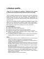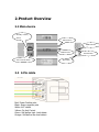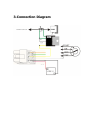
1
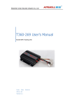
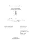
Amwell GPS 101A User’s Manual For simple and cheap solution Liven 2010‐12‐23 MENU 1. Product profile ......................................................................................................................... 3 2. Product Overview .................................................................................................................... 4 2.1 Main device .................................................................................................................. 4 2.2 6 Pin cable ................................................................................................................... 4 3. Connection Diagram ............................................................................................................... 5 4. Product Initialization ............................................................................................................... 6 4.1 Prepare works.............................................................................................................. 6 4.2 Setting steps ................................................................................................................ 6 5. Functions .................................................................................................................................. 8 5.1 Real-time positioning .................................................................................................. 8 5.2 Report by timing interval ........................................................................................... 8 5.3 Mileage statistics ......................................................................................................... 8 5.4 Stop Engine (oil) / Recover Engine (oil) .................................................................. 8 5.5 Alarm functions ........................................................................................................... 9 5.5.1 Over speed alarm ............................................................................................ 9 5.5.2 Terminal main power cut alarm .................................................................... 9 5.5.3 Fatigue driving alarm ...................................................................................... 9 5.5.4 Custom Sensor Alarm ..................................................................................... 9 5.5.5 SIM card removed alarm ............................................................................. 10 5.6 Remote Control Functions ....................................................................................... 10 5.6.1 Terminal Status Inquiry ................................................................................ 10 5.6.2 Restore to factory default ............................................................................ 11 5.6.3 Remote restart Device .................................................................................. 11 6. Accessories ............................................................................................................................ 12 1.Product profile Thank you for choosing the company's T360-101A GPS tracking products, please carefully read the instructions before operating. T360-101A satellite positioning system combined with anti-theft, positioning, monitor and observe, alarm for help, advertising, vehicle scheduling and tracking functions, it’s easy to use, easy to operate, the characteristics of a full-featured, the main applies to vehicles and other mobile object location and tracking services. T360-101A fully supports the GPRS network data transmission function, GPRS platform can be combined with software to make it more widely used in large-scale cluster monitoring, emergency scheduling, location-based services, fleet management, traffic safety management and many other fields. Product Features: Support GPS real-time tracking. Support GPRS network data transmission. Support for multi-directional terminal parameter settings. Support for automatic sleep, standby operating current is only 80mA. Support for peer-to-peer monitoring, point to group control, group all-round monitoring of the group. Combined with positioning, monitoring control, alarm, such as first aid and tracking multiple functions with a full range of integrated products. Note: Herein after referred to as the 【default user】refers to has been set and saved to the product of all numbers communications devices. . If an error or a write command to send messages of non-default number of instructions, this product will ignore it. All input commands must be uppercase letters in English, and need to use Standard English punctuation, must not use other input method instead of the English punctuation. And all SMS commands are no space character between the contents. This product is factory default password for 【1234】, convenience-oriented brochures to explain the following command operation for some of those involved in your password are the product's default password 【1234】 This product is not waterproof, choose the dry location to install, and pay attention to water moisture. Please installed and use this product properly. 2.Product Overview 2.1 Main device Standby battery switch GPS antenna GSM indicator GSM antenna Anti‐remove switch GPS indicator 6pin cable 2.2 6 Pin cable Red: Power Positive pole Black: Power negative pole White: ACC detect Yellow: Cut fuel Control Green: Self-define high- level detect Orange: Self-define low-level detect 3.Connection Diagram 4.Product Initialization After you get 101A product, please familiar with it and test it before you install it in a Car. Please test it according to the following steps. 4.1 Prepare works Amwell GPS product Serial setting cable and TEsetting software Local GPRS SIM card 12V DC power supplier Computer with COM port (if do not have COM port, can use USB to serial cable instead) GPSclient software SQL SERVER 2000 or SQL SERVER 2005 Teamviewer (Optional, it is used for remote assist, used when you need get help from supplier) 4.2 Setting steps Step1. Insert SIM card into the Amwell GPS device. Step2. Connect the antennas (GSM antenna and GPS antenna) to device Step3. Connect the power cable to 12V DC power supplier (according to the diagram of device connection in 3.0) Step4. Send command to set parameters. Devices need parameters to connect to server via GPRS, such as Server IP/Port and APN. The following table shows commands for setting these parameters. No. Name 1 Set server IP/Port 2 Set Device ID 3 4 Set APN Restart Device Command AS1234IPPO:119.147.23.108;7 777# Reply IPPO:119.147.23.108;7777OK Instruct Reply content is “IP” “Port” AS1234IDDO:00012345# IDDO:00012345;OK Current“ID” AS1234APN:CMNET# APN:CMNET;OK APN setting AS1234USER:GPRS# USER:GPRS;OK AS1234GPRSPASS:GPRS# GPRSPASS:GPRS;OK AS1234RSGS# GSM/restart; OK Device restart All parameters 5 Factory set ASAX*%UPAS# PASSWORD:1234;OK recover to factory, beside IP/Port/ID/APN 6 State query AS1234STATE# 7 Position query AS1234WHERE# Lat:+22.59429;Lon:+113.86971; 8 Cut engine AS1234ENGINE:OFF ENGINE:OFF;OK 9 Restore fuel AS1234ENGINE:ON ENGINE:ON;OK Note: 1) All the command Character must write correctly, include punctuation/super-case or lower-case, any incorrect input will cause command error. 2) The SIM card inserted in device must open SMS function, if not open will cause all the command do not receive and execute 3) Device default password is: 1234. Step5. Install SQL Server 2000 or SQL Server 2005. (According to the instruction of Microsoft). Step6. Build a new database named localGPSDB in SQL Server, and run script localGPSDB.sql (use localGPSDB). Step7. Install GPSclient Step8. Add the information of the device into database (include S/N (TEID), car no, device type … and so on) If you have any questions, please install Teamviewer, then contact will our technique support. 5. Functions 5.1 Real-time positioning Monitoring center can directly locate the specified vehicle terminal call view, in-car terminal will immediately return to the central monitoring platform details such as vehicle location data. Location information mainly include: time, longitude, latitude, speed, location, location signs, vehicles and terminal status. 5.2 Report by timing interval Monitoring center can specify the car back to the terminal for data transmission interval timing settings, factory default upload interval of 30 seconds, adjustable range is 5-65535 seconds; if interval is set to less than “5 seconds ", the terminal device will automatically return to the "5 seconds." 5.3 Mileage statistics The beginning of this equipment from loading automatically calculate mileage, and mileage statistics from time to time to report to center platform, the center can take advice on car mileage table stored data; also the centers can clear the vehicle mileage data stored by platform, or be derived in accordance with set time-related mileage statistics. Mileage statistics < "16000km". 5.4 Stop Engine (oil) / Recover Engine (oil) Monitoring center can be personalized to the designated vehicle and a remote disconnect the circuit or to restore the circuit, when the vehicle terminal receives instruction on the oil line or restore the circuit to take down oil movements. (Note: Equipment in the implementation of action off the oil when it is the first implementation of the three sub-batch 1 seconds off the oil 【off 15 seconds】 ---- restored to the 4th when completely cut off oil line) 5.5 Alarm functions 5.5.1 Over speed alarm Traffic speed alarm refers to the device in accordance with the speed to allow the user to set the value of constantly monitoring the vehicle speed, when the vehicle speed exceeds preset allowable value, the device will send over speed alarm data reported to the Center, when the speed dropped to the default values that the abolition of alarm. Center received alarm data may confirm or cancel the alarm. Driving speed alarm set value in the 0-255 (km) range. 5.5.2 Terminal main power cut alarm When the vehicle power supply was cut off the terminal will issued a power off warning in 3 seconds, at the same time start the backup battery power supply (can last around 4 hours), again automatically detect whether the alarm is canceled after 30 seconds, Center received alarm information could confirm and cancel alarm. If the terminal is currently in standby sleep mode, will wake-up immediately to activate and exit standby mode, will also alarm to the center. Note: The brown-out detection voltage threshold value <7V (DC). 5.5.3 Fatigue driving alarm Overtime drive; also known as fatigue, driving is mainly a continuous monitoring of driver fatigue, driving out to bring the traffic safety problems. When the alarm function to open overtime driving, driving conditions to determine the state of ACC in the ON state duration beyond the default values, is central issue, when the ACC began to open the device time, when the preset value is exceeded, the device will be immediately sent to the Center of fatigue driving alert data, the user can confirm or cancel the alarm on demand. 5.5.4 Custom Sensor Alarm The device with 2-way accustom test line (the test line of the definition and installation please refer to the section described in the previous installation of the 【Connection Diagram】) in order to meet specific customer needs. When the user needs to customize sensor alarm function can be defined according to their own needs the name of the line alarm. As defined by the test line before it is triggered, the device will immediately send a custom alarm to the central data center can be confirmed after the receipt of alarm information and cancel alarm. 5.5.5 SIM card removed alarm There have an anti-remove switch beside the SIM card plate. If the plate been removed to get the SIM card, device will upload alarm information immediately. It is very important alarm and can only be send once (Can’t send any information after SIM card being removed.). 5.6 Remote Control Functions 5.6.1 Terminal Status Inquiry There have a status inquiry command in software platform, when sending this command to device, device will reply a status code like this: "wXtX, spX, stpX, drX, idlX, stfX, csX, alrX, ocX, msX" It means: wt: “w” means the position behind the monitor settings (1 timer, 2 interval, other means of closure), “ t “interval after that value, stp : over speed dr: fatigue set idl: idling set stf: the same as protocol “stf” status cs :the same as “ st1-st4”, 4 bytes means car staus definition alr : The same as “82” alarm status 3 bytes oc :cut of fuel, 1: cut off fuel;”0” means normal status ms: program state machine status bits (0- module initialization, 2- check signals, 4- check registration, 8- gprs connecting, 10- udp connecting, 20- connecting center or to connect to normal center on standby, 40-gprs disconnect, 80-call state) sp: over speed stp : said the parking timeout threshold, dr said driver set threshold, idl said the idle threshold, stf with the protocol definition stf status bits, cs with the protocol definition st1-st4, 4 bytes of vehicle conditions and definitions, alr with the protocol definition 82 alarm state 3 bytes, oc-off state gasoline and electricity, 1 for off petrol and electricity, 0 is normal, 5.6.2 Restore to factory default To restore factory settings is to clear the main terminal settings, so that terminal back to the original state. This feature will not clear the set of the IP, ID, APN, time zone, standby mode. Note: double check the communication parameters are correct before restore the factory setting 5.6.3 Remote restart Device Abnormal when an individual terminals on-line or for other reasons need to restart the device, the user can correspond to the terminal through the platform to restart the instruction issued. 6.Accessories 101A-type vehicle terminal 1 sets (built-in battery) 6 PIN control cable 1 GPRS communications antenna 1 GPS positioning antenna 1 Breaking the fuel Relay 1 (DC12V 40A) (If you need to 24V relay please advise in advance) Device fixed Ties 3 Mount Patch 2 pairs