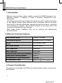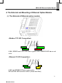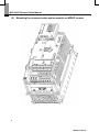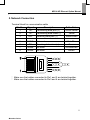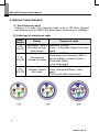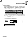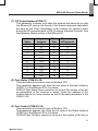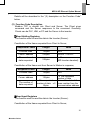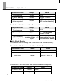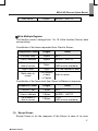
1
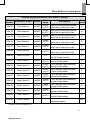
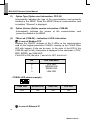
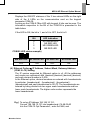
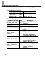
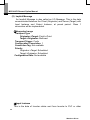
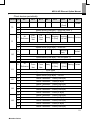
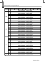
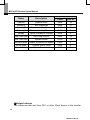
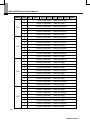
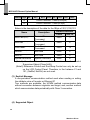
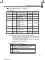
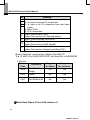
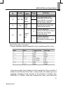
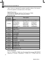
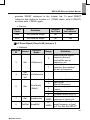
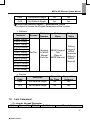
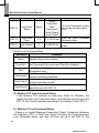
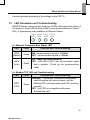
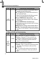
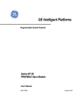
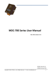
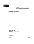
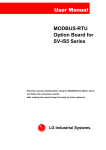
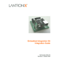
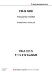
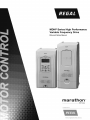
MDLV-HP Ethernet Option Manual Before using the product, thank you for using our MDLV-HP Ethernet option module. Safety Instruction To prevent injury and danger in advance for safe and correct use of the product, be sure to follow the Safety Instructions. The instructions are divided as ‘WARNING’ and ‘CAUTION’ which mean as follow. WARNING CAUTION This symbol indicates the possibility of death or serious injury. This symbol indicates the possibility of injury or damage to property. The meaning of each symbol in this manual and on your equipment is as follows. This is the safety alert symbol. This is the dangerous voltage alert symbol. After reading the manual, keep it in the place that the user always can Contact easily. Before you proceed, be sure to read and become familiar with the safety precautions at the beginning of this manual. If you have any questions, seek expert advice before you proceed. Do not proceed if you are unsure of the safety precautions or any procedure. WARNING Be cautious about dealing with CMOS elements of option board. It can cause malfunction by static electricity. Connection changing like communication wire change must be done with power off. It can cause communication faulty or malfunction. Be sure to connect exactly between Inverter and option board. It can cause communication faulty or malfunction. Check parameter unit when setting parameter. It can cause communication faulty. 1 Marathon Drives MDLV-HP Ethernet Option Manual 1. Introduction Ethernet communication option module connects the MDHP inverter to the Ethernet network. It supports 2 kinds of protocol, Modbus/TCP and Ethernet/IP. Controlling and monitoring of inverter can be done by PLC sequence program or any Master Module. Since Ethernet which constitutes Internet has been used and IPv4 has been supported, wherever Internet can be done, controlling and monitoring is possible. But, Ethernet network of the factory has to be connected to Internet through Gateway. With simple wiring, installation time can be reduced and maintenance becomes easier. 2. Ethernet Technical Features Transmission Speed 10Mbps, 100Mbps Transmission Method Baseband (Half, Full Duplex) Max. Extended Distance between Nodes 100m (Node - Hub) Max. Node Number Hub connection Auto Negotiation Supported Max. Frame size 1500 Bytes Communication Zone Access Method Frame Error Checking Method Recommended Connecting Socket CSMA/CD CRC32 3 Socket UTP, FTP, STP (Refer to page 6 for details.) Recommended Cable 3. Product Constituents This product is consisting of the Ethernet communication module, a screw and User Manual. 2 Marathon Drives MDLV-HP Ethernet Option Manual 4. The External and Mounting of Ethernet Option Module (1) The External of Ethernet option module <Modbus TCP LED Composition> LINK LED SPEED LED CPU LED ERROR LED LINK, SPEED and CPU LED have a green color. ERROR LED has a red color. <Ethernet IP LED Composition> LINK LED SPEED LED NS LED MS LED LINK and SPEED LED are a green color. MS and NS LED have two colors. (Green and Red) 3 Marathon Drives MDLV-HP Ethernet Option Manual (2) Mounting the communication option module on MDHP inverter 4 Marathon Drives MDLV-HP Ethernet Option Manual 5. Network Connection Terminal block for communication cable Pin No. 1 2 3 4 5 6 7 8 8 Signal TX+ TXRX+ NONE NONE RXNONE NONE Description Transmitting data plus (+) Transmitting data minus (-) Receiving data plus (+) Not used Not used Receiving data minus (-) Not used Not used Cable Color White/Yellow Yellow White/Green Blue White/Blue Green White/Brown Brown 8 7 6 5 4 3 1 2 1 ※ Make sure that cables connected to Pin1 and 2 are twisted together. ※ Make sure that cables connected to Pin3 and 6 are twisted together. 5 Marathon Drives MDLV-HP Ethernet Option Manual 6. Network Cable Standard (1) Used frequency band Category 5 is used. The frequency band is up to 100 MHz, Channel performance is up to 60MHz and Transmission speed is up to 100Mbps. (2) Cable type of twisted pair cable Classification Details Purpose of cable UTP (U.UTP) Unshielded Twisted Pair cable for highspeed signal FTP (S.UTP) Foil screened Twisted Pair cable STP (S.STP) Shielded Twisted Pair cable Maximum 200MHz Voice + Information (Data)+Low video signal Maximum 100MHz Electromagnetic interruption (EMI) or electric stability considered Voice + Information (Data) + Low Video signal Maximum 500MHz Voice +Information(Data)+ Video signal 75Ω coaxial cable replacement 6 Marathon Drives MDLV-HP Ethernet Option Manual 7. Selecting Protocol For using the MDHP Ethernet option module, there are 2 kinds of protocol, Modbus TCP and Ethernet IP. You can select one of the protocols by selecting the No.1 switch. The switch is placed next to the RJ45 connector for Ethernet cable. No. 2, 3 and 4 of switch are not available. Switch State Protocol OFF (Switch at the upper position) Modbus TCP ON (Switch at the lower position Ethernet IP If the option module is operating, protocol will be not changed even if switch selection is changed. Protocol is determined by the state of switch when the option module is turned On or the inverter is initialized by ‘Yes’ execution of COM-94 Comm Update. <Front side of Ethernet Option module> RJ 45 1 2 3 4 Protocol Selecting Switch 7 Marathon Drives MDLV-HP Ethernet Option Manual 8. Ethernet Option and Related Keypad Parameters The functions below are the inverter parameters which shows the information related with the Modbus TCP and Ethernet IP. In the parameter column, the “M” stands for the parameters used for Modbus TCP, and “E” stands for the parameters used for Ethernet IP. Related keypad parameter with MDHP Ethernet Code Set Description Number Parameter Name Default value CNF-30 Option-1 Type - - COM-06 FBus S/W Ver - - COM-09 FBus Led - - COM-10 Opt Parameter1 0x0000 COM-11 Opt Parameter2 0x0000 COM-12 Opt Parameter3 0x0000 COM-13 Opt Parameter4 0x0000 COM-14 Opt Parameter5 0x0000 COM-15 Opt Parameter6 0x0000 0x0000 ~0xFFFF 0x0000 ~0xFFFF 0x0000 ~0xFFFF 0x0000 ~0xFFFF 0x0000 ~0xFFFF 0x0000 ~0xFFFF COM-16 Opt Parameter7 0 0~2 COM-17 Opt Parameter8 (Note1) COM-18 Opt Parameter9 (Note1) 0 0 0~11 0~11 COM-30 ParaStatus Num 3 0~8 COM-31 Para Status-1 0x000A 0x0000 ~0xFFFF COM-32 Para Status-2 0x000D 0x0000 ~0xFFFF Indicates name of the communication card installed in the inverter (Ethernet). Indicates version of the communication card installed in the inverter. Shows the ON/OFF data of the LED on the Ethernet communication card. Protocol M/E M/E M/E Sets up the IP Address. M/E Sets up the Subnet Mask. M/E Sets up the Gateway Address. M/E Sets up the Ethernet communication rate. CIP Input Instance CIP Output Instance Automatically set up according to the CIP Input Instance. Sets up the inverter data address which will be read by the client. Sets up the inverter data address which will be read by the client. 8 Marathon Drives M/E E E E E E MDLV-HP Ethernet Option Manual Related keypad parameter with MDHP Ethernet Code Number Parameter Name Default Set value COM-33 Para Status-3 0x000F 0x0000 ~0xFFFF COM-34 Para Status-4 0x0000 0x0000 ~0xFFFF COM-35 Para Status-5 0x0000 0x0000 ~0xFFFF COM-36 Para Status-6 0x0000 0x0000 ~0xFFFF COM-37 Para Status-7 0x0000 0x0000 ~0xFFFF COM-38 Para Status-8 0x0000 0x0000 ~0xFFFF COM-50 Para Ctrl Num 2 0~8 COM-51 Para Control-1 0x0005 0x0000 ~0xFFFF COM-52 Para Control-2 0x0006 0x0000 ~0xFFFF COM-53 Para Control-3 0x0000 0x0000 ~0xFFFF COM-54 Para Control-4 0x0000 0x0000 ~0xFFFF COM-55 Para Control-5 0x0000 0x0000 ~0xFFFF COM-56 Para Control-6 0x0000 0x0000 ~0xFFFF COM-57 Para Control-7 0x0000 0x0000 ~0xFFFF COM-58 Para Control-8 0x0000 0x0000 ~0xFFFF COM-94 Comm Update - - Protocol Description Sets up the inverter data address which will be read by the client. Sets up the inverter data address which will be read by the client. Sets up the inverter data address which will be read by the client. Sets up the inverter data address which will be read by the client. Sets up the inverter data address which will be read by the client. Sets up the inverter data address which will be read by the client. Automatically set up according to the CIP Output Instance. The Client sets up the reference Inverter Data Address. The Client sets up the reference Inverter Data Address. The Client sets up the reference Inverter Data Address. The Client sets up the reference Inverter Data Address. The Client sets up the reference Inverter Data Address. The Client sets up the reference Inverter Data Address. The Client sets up the reference Inverter Data Address. The Client sets up the reference Inverter Data Address. Updates communication related keypad parameters. E E E E E E E E E E E E E E E M/E * (Note1) Since this is an optional parameter exclusively for Ethernet IP, it is not displayed on the Loader in case of Modbus TCP. 9 Marathon Drives MDLV-HP Ethernet Option Manual (1) Option Type (Option card information, CFG-30) Automatically indicates the type of the communication card presently installed in the MDHP. When the MDHP Ethernet communication card is installed, “Ethernet” is displayed. (2) Option Version (Option version information, COM-06) Automatically indicates the version of the communication card presently installed in the MDHP. (3) FBus Led (COM-09) – Indication of LED information ① In case of Modbus/TCP Displays the ON/OFF statuses of the 4 LEDs on the communication card on the keypad parameter COM-09. Looking up the COM-9 FBus LED with keypad, 4 bits can be seen. In the order of the LED of the COM-09 (right to left), information is displayed in the said order of CPU, ERR, SPEED, and LINK LED. If the LED is ON, the bit is 1, and of it is OFF, the bit is 0. Bit 0 1 2 3 LED Indication CPU LED ERROR LED SPEED LED LINK LED COM-09 LED status example) LINK LED SPEED LED ERR LED CPU LED OFF ON ON ON ② In case of Ethernet IP 10 Marathon Drives MDLV-HP Ethernet Option Manual Displays the ON/OFF statuses of the 2 two-colored LEDs on the right side of the 4 LEDs on the communication card on the keypad parameter COM-09. Looking up the COM-9 FBus LED with keypad, 4 bits can be seen. The information respective to the Bit of the COM-09 is presented in the table below. If the LED is ON, the bit is 1, and of it is OFF, the bit is 0. Bit LED Indication 0 1 2 3 NS GREEN LED NS RED LED MS GREEN LED MS RED LED COM-09 LED status example) MS Red LED MS Green LED OFF ON NS Red LED NS Green LED OFF ON (4) Ethernet Option의 IP Address, Subnet Mask, Gateway Address (COM-10~15) Setting The IP version supported by Ethernet option is v4. All the addresses and masks are expressed with (decimal).(decimal).(decimal).(decimal) and each decimal number is 0~255. In the Ethernet option, decimal numbers are entered with hexadecimals. In particular, (hexadecimal) . (hexadecimal) . (hexadecimal) . (hexadecimal) and each hexadecimal is 00~FF. The hexadecimals are entered by being divided into two upper scale hexadecimals and two lower scale hexadecimals. The higher code number represents the lower hexadecimals. E.g.) To set up IP Address 196.168.10.131; Convert 196.168.10.131 into hexadecimal: C4.A8.0A.83 Into the COM-10 Opt Parameter1, enter 0xC4A8, and 11 Marathon Drives MDLV-HP Ethernet Option Manual Into the COM-11 Opt Parameter2, enter 0x0A83. (5) Ethernet Speed (COM-16) Ethernet speed can be set up within the range of 0~2. ` Set Value 0 1 2 Speed Set the speed automatically 100Mbps 10Mbps Automatic speed setting function automatically sets up the highest speed in the network. If the Link LED does not light up when connected to the hub in automatic speed setting mode (Auto Negotiation), the connection will be made at changed speed. (6) CIP Input Instance(COM-17) This parameter is shown only when the protocol has been set up with the Ethernet IP sets up the format of the inverter state data which are sent by the inverter to the Client (Originator) during the I/O communication of CIP (Common Industrial Protocol). See the Assembly Object section of the Ethernet IP. Set The number Input Instance Data Size Value or Parameter 0 70 4 X 1 71 4 X 2 110 4 X 3 111 4 X 4 141 2 1 5 142 4 2 6 143 6 3 7 144 8 4 8 145 10 5 9 146 12 6 10 147 14 7 11 148 16 8 12 Marathon Drives MDLV-HP Ethernet Option Manual (7) CIP Output Instance(COM-17) This parameter is shown only when the protocol has been set up with the Ethernet IP sets up the format of the inverter reference data which are sent by the Client (Originator) to the inverter for inverter control during the I/O communication of CIP (Common Industrial Protocol). See the Assembly Object section of the Ethernet IP. Set Value 0 1 2 3 4 5 6 7 8 9 10 11 Input Instance 20 21 100 101 121 122 123 124 125 126 127 128 Data Size 4 4 4 4 2 4 6 8 10 12 14 16 The number of Parameter X X X X 1 2 3 4 5 6 7 8 (8) Para Status (COM-30~38) This parameter is not used in case of Modbus TCP. This parameter appears only when the set value of the Input Instance (COM-17) in the Ethernet IP is 4 or above. COM-30 Para Status Num cannot be set up but the number of the set up parameters of the instance is shown. Enter the address of the inverter data at the same number as that of the said parameters in the COM-31~38. (9) Para Control (COM-50~58) This parameter is not used in case of Modbus TCP. This parameter appears only when the set value of the Output Instance (COM-18) in the Ethernet IP is 4 or above. COM-50 Para Ctrl Num cannot be set up but the number of the set up 13 Marathon Drives MDLV-HP Ethernet Option Manual parameters of the instance is shown. Enter the address of the inverter data, which will make use of the reference data of the Client (Originator), at the same number as that of the said parameters in the COM-51~58. (10) Comm UpDate (COM-94) At power on, the Option Parameters are expressed by the values set up in the Option, however, not reflected immediately when set up. If the Comm Update is set to ‘Yes,’ this value is reflected on the Modbus/TCP communication card and only this card will be restarted. 9. Inverter Communication Address See Chapter 11. Communication Function, Inverter IS-7 Manual. 10. Modbus/TCP Frame (1) Modbus/TCP Frame Composition MBAP Header( 7 bytes) PDU (5 bytes ~) Generally, Ethernet uses Ethernet II Frame. MODBUS Application Protocol Header (MBAP Header) MBAP Header constitution is presented below. Section Length Description Unique transmission number, which is Transaction 2 Bytes increased by 1 each time the Client sends Identifier Data Frame to the Server. Protocol Identifier 2 Bytes Fixed at 0. The Data Frame length of the Modbus, Length 2 Bytes representing the length (in byte unit) from the Unit Identifier in the MBAP Header. When the Modbus TCP and Modbus RTU are connected via gate, Slave number is Unit Identifier 1 Bytes indicated. If Modbus TCP only is used, this is fixed to 0xFF. Protocol Data Unit (PDU) This is the practical data of the Modbus TCP consists of Function Code and Data. 14 Marathon Drives MDLV-HP Ethernet Option Manual Details will be described in the “(2) description on the Function Code” below. (2) Function Code Description Modbus TCP is divided into Client and Server. The Client gives command and the Server responses to the command. Generally, Clients can be PLC, HMI, or PC and the Server is the inverter. ①Read Holding Registers The function used to read the data in the Inverter (Server). Constitution of the frame requested from Client to Server; Requested Frame Length Value Function code 1 Bytes 0x03 Comm. address 2 Bytes 0x0000 ~ 0xFFFF The number of data requested 2 Bytes 1~16 (MD Inverter standard) Constitution of the frame sent from Server to Master in response; Response Frame Length Function code 1 Bytes Comm. address The number of data requested Value 0x03 2 x The requested number of data The requested Value of the data of the number of data x 2 given number from the Bytes communication address 1 Bytes ②Read Input Registers The function used to read the data in the Inverter (Server). Constitution of the frame requested from Client to Server; 15 Marathon Drives MDLV-HP Ethernet Option Manual Requested Frame Length Value Function code 1 Bytes 0x04 Comm. address The number of data requested 2 Bytes 0x0000 ~ 0xFFFF 1~16 (MD Inverter standard) 2 Bytes Constitution of the frame sent from Server to Master in response; Response Frame Length Function code 1 Bytes Comm. address The number of data requested Value 0x03 2 x The requested number of data The requested Value of the data of the number of data x 2 given number from the Bytes communication address 1 Bytes ③Write Single Register The function used to change one of the data in the Inverter (Server). Constitution of the frame requested from Client to Server; Requested Frame Length Value Function code 1 Bytes 0x06 Comm. address 2 Bytes 0x0000 ~ 0xFFFF Data value 2 Bytes 0x0000 ~ 0xFFFF Constitution of the frame sent from Server to Master in response; Response Frame Length Value Function code 1 Bytes 0x06 Comm. address 2 Bytes 0x0000 ~ 0xFFFF 16 Marathon Drives MDLV-HP Ethernet Option Manual Data Value 2 Bytes 0x0000 ~ 0xFFFF ④Write Multiple Register The function used to change from 1 to 16 of the Inverter (Server) data consecutively. Constitution of the frame requested from Client to Server; Requested Frame Length Function code 1bytes 0x10 Comm. address The number of data to revise 2bytes 0x0000 ~ 0xFFFF 1~16 (MD Inverter standard) Byte Count 1byte Data value to revise The number of data x 2 bytes 2byte Value 2 X The number of data Data to revise Constitution of the frame sent from Server to Master in response; (3) Response Frame Length Value Function Code 1 Bytes 0x10 Comm. address 2 Bytes 0x0000 ~ 0xFFFF The number of data to revise 2 Bytes 1~16 (MD Inverter standard) Except Frame Except Frame is for the response of the Server in case of an error 17 Marathon Drives MDLV-HP Ethernet Option Manual occurred in the execution of the frame requested by a Client. Exception Frame Composition Error Frame Length Error Code 1bytes Exception Code 1bytes Value 0x80 + Requested function code from client 0x0000 ~ 0xFFFF Exception Code Type Exception Code Type Code ILLEGAL FUNCTION 0x01 ILLEGAL DATA ADDRESS 0x02 ILLEGAL DATA VALUE 0x03 SLAVE DEVICE FAILURE 0x04 SLAVE DEVICE BUSY 0x06 WRITE PERMITION ERROR 0x20 Description When unsupported function is requested Request or modification of the data in unused address When trying to modify data to a value out of the allowable range Server has an error (Error in CAN communication with Inverter, error in Option initialization, failure in data communication with Inverter) Server is unable to respond because it is executing another process (Inverter parameter initializing, initial setting of Option, etc.) When trying to change a parameter which is prohibited from changing. (A unique code of LS Inverters) 18 Marathon Drives MDLV-HP Ethernet Option Manual 11. Ethernet IP (1) Basic Constitution of Protocol The Ethernet IP is a protocol which is implemented with the CIP (Common Industrial Protocol), specified by the ODVA, using TCP and UDP. Originator: the device which is requesting connection. Also called client. The device can be PLC or Scanner. Target: the device which responds to the request for connection. Also called server. The device here is Inverter. 19 Marathon Drives MDLV-HP Ethernet Option Manual (2) Implicit Message An Implicit Message is also called an I/O Message. This is the data communicated between the Client (Originator) and Server (Target) with Input Instance and Output Instance, at preset period. Class 1 connection will be implemented. ①Supported range Transport Type Originator->Target: Point to Point Target->Originator: Multicast Transport Trigger: Cyclic Configuration Connection: 1 Connection Tag: Not available Priority Originator->Target: Scheduled Target->Originator: Scheduled Configuration Data: Not available ②Input Instance This is the data of Inverter status sent from Inverter to PLC or other 20 Marathon Drives MDLV-HP Ethernet Option Manual Client devices periodically. Instance Byte Bit 7 Bit 6 Bit 5 Bit 4 Bit 3 1 2 3 0 71 At Reference Ref From Net 1 2 3 111 141 142 143 1 Faulted Ctrl From Net Ready Running Running Warning Faulted 2 (Rev) 1 (Fwd) Drive State Speed Actual (Low Byte) – RPM unit Speed Actual (High Byte) – RPM unit Running1 (Fwd) 1 2 3 0 Bit 0 Speed Actual (Low Byte) – RPM unit (Note 1) Speed Actual (High Byte) – RPM unit 0 110 Bit 1 Running 1 (Fwd) 0 70 Bit 2 Faulted Speed Actual (Low Byte) – Hz unit (Note 1) Speed Actual (High Byte) – Hz unit At Reference Ref From Net Ctrl From Net Ready Running Running Warning Faulted 2 (Rev) 1 (Fwd) Drive State 2 Speed Actual (Low Byte) – Hz unit 3 Speed Actual (High Byte) – Hz unit 0 Status Parameter - 1 data (Low Byte) 1 Status Parameter - 1 data (Hi Byte) 0 Status Parameter - 1 data (Low Byte) 1 Status Parameter - 1 data (Hi Byte) 2 Status Parameter - 2 data (Low Byte) 3 Status Parameter - 2 data (Hi Byte) 0 Status Parameter - 1 data (Low Byte) 1 Status Parameter - 1 data (Hi Byte) 2 Status Parameter - 2 data (Low Byte) 3 Status Parameter - 2 data (Hi Byte) 4 Status Parameter - 3 data (Low Byte) 21 Marathon Drives MDLV-HP Ethernet Option Manual Instance Byte 144 145 146 147 Bit 7 Bit 6 Bit 5 Bit 4 Bit 3 Bit 2 5 Status Parameter - 3 data (Hi Byte) 0 Status Parameter - 1 data (Low Byte) 1 Status Parameter - 1 data (Hi Byte) 2 Status Parameter - 2 data (Low Byte) 3 Status Parameter - 2 data (Hi Byte) 4 Status Parameter - 3 data (Low Byte) 5 Status Parameter - 3 data (Hi Byte) 6 Status Parameter - 4 data (Low Byte) 7 Status Parameter - 4 data (Hi Byte) 0 Status Parameter - 1 data (Low Byte) 1 Status Parameter - 1 data (Hi Byte) 2 Status Parameter - 2 data (Low Byte) 3 Status Parameter - 2 data (Hi Byte) 4 Status Parameter - 3 data (Low Byte) 5 Status Parameter - 3 data (Hi Byte) 6 Status Parameter - 4 data (Low Byte) 7 Status Parameter - 4 data (Hi Byte) 8 Status Parameter - 5 data (Low Byte) 9 Status Parameter - 5 data (Hi Byte) 0 Status Parameter - 1 data (Low Byte) 1 Status Parameter - 1 data (Hi Byte) 2 Status Parameter - 2 data (Low Byte) 3 Status Parameter - 2 data (Hi Byte) 4 Status Parameter - 3 data (Low Byte) 5 Status Parameter - 3 data (Hi Byte) 6 Status Parameter - 4 data (Low Byte) 7 Status Parameter - 4 data (Hi Byte) 8 Status Parameter - 5 data (Low Byte) 9 Status Parameter - 5 data (Hi Byte) 10 Status Parameter - 6 data (Low Byte) 11 Status Parameter - 6 data (Hi Byte) 0 Status Parameter - 1 data (Low Byte) Bit 1 Bit 0 22 Marathon Drives MDLV-HP Ethernet Option Manual Instance Byte 148 Bit 7 Bit 6 Bit 5 Bit 4 Bit 3 Bit 2 1 Status Parameter - 1 data (Hi Byte) 2 Status Parameter - 2 data (Low Byte) 3 Status Parameter - 2 data (Hi Byte) 4 Status Parameter - 3 data (Low Byte) 5 Status Parameter - 3 data (Hi Byte) 6 Status Parameter - 4 data (Low Byte) 7 Status Parameter - 4 data (Hi Byte) 8 Status Parameter - 5 data (Low Byte) 9 Status Parameter - 5 data (Hi Byte) 10 Status Parameter - 6 data (Low Byte) 11 Status Parameter - 6 data (Hi Byte) 12 Status Parameter - 7 data (Low Byte) 13 Status Parameter - 7 data (Hi Byte) 0 Status Parameter - 1 data (Low Byte) 1 Status Parameter - 1 data (Hi Byte) 2 Status Parameter - 2 data (Low Byte) 3 Status Parameter - 2 data (Hi Byte) 4 Status Parameter - 3 data (Low Byte) 5 Status Parameter - 3 data (Hi Byte) 6 Status Parameter - 4 data (Low Byte) 7 Status Parameter - 4 data (Hi Byte) 8 Status Parameter - 5 data (Low Byte) 9 Status Parameter - 5 data (Hi Byte) 10 Status Parameter - 6 data (Low Byte) 11 Status Parameter - 6 data (Hi Byte) 12 Status Parameter - 7 data (Low Byte) 13 Status Parameter - 7 data (Hi Byte) 14 Status Parameter - 8 data (Low Byte) 15 Status Parameter - 8 data (Hi Byte) Bit 1 Bit 0 Below is the description of the data for the 0,1Byte of 70,71,110,111. 23 Marathon Drives MDLV-HP Ethernet Option Manual Name Description Faulted Inverter Error Warning Not Supported Running1 Motor is running Forward Running2 Motor is running Reverse Ready Motor is ready to running Ctrl From Net Run/Stop control Ref From Net Speed control At Reference Reach at reference Speed Drive State Current Motor State Speed Actual Speed Command Related Attribute Class Attr. ID 0x29 10 0x29 11 0x29 7 0x29 8 0x29 9 0x29 15 0x2A 29 0x2A 3 0x29 6 0x2A 7 ③Output Instance The reference data sent from PLC or other Client device to the Inverter 24 Marathon Drives MDLV-HP Ethernet Option Manual periodically. Instance Byte Bit 7 Bit 6 Bit 5 Bit 4 Bit 3 0 2 Speed Reference (Low Byte) – RPM unit 3 Speed Reference (High Byte) – RPM unit NetRef NetCtrl (Note 2) (Note2) Fault Reset 100 0 2 Speed Reference (Low Byte) – RPM unit 3 Speed Reference (High Byte) – RPM unit 1 Fault Reset Run Fwd Run Fwd 0 2 Speed Reference (Low Byte) – Hz unit 3 Speed Reference (High Byte) – Hz unit 0 101 Run Rev 1 0 Bit 0 Run Fwd 1 0 21 Bit 1 Fault Reset 0 20 Bit 2 Fault Reset NetRef NetCtrl Run Rev 1 0 2 Speed Reference (Low Byte) – Hz unit 3 Speed Reference (High Byte) – Hz unit 0 Control Parameter - 1 data (Low Byte) 1 Control Parameter - 1 data (Hi Byte) 0 Control Parameter - 1 data (Low Byte) 1 Control Parameter - 1 data (Hi Byte) 2 Control Parameter - 2 data (Low Byte) 3 Control Parameter - 2 data (Hi Byte) Run Fwd 121 122 25 Marathon Drives MDLV-HP Ethernet Option Manual Instance Byte Bit 7 123 124 125 126 Bit 6 Bit 5 Bit 4 Bit 3 Bit 2 Bit 1 0 Control Parameter - 1 data (Low Byte) 1 Control Parameter - 1 data (Hi Byte) 2 Control Parameter - 2 data (Low Byte) 3 Control Parameter - 2 data (Hi Byte) 4 Control Parameter - 3 data (Low Byte) 5 Control Parameter - 3 data (Hi Byte) 0 Control Parameter - 1 data (Low Byte) 1 Control Parameter - 1 data (Hi Byte) 2 Control Parameter - 2 data (Low Byte) 3 Control Parameter - 2 data (Hi Byte) 4 Control Parameter - 3 data (Low Byte) 5 Control Parameter - 3 data (Hi Byte) 6 Control Parameter - 4 data (Low Byte) 7 Control Parameter - 4 data (Hi Byte) 0 Control Parameter - 1 data (Low Byte) 1 Control Parameter - 1 data (Hi Byte) 2 Control Parameter - 2 data (Low Byte) 3 Control Parameter - 2 data (Hi Byte) 4 Control Parameter - 3 data (Low Byte) 5 Control Parameter - 3 data (Hi Byte) 6 Control Parameter - 4 data (Low Byte) 7 Control Parameter - 4 data (Hi Byte) 8 Control Parameter - 5 data (Low Byte) 9 Control Parameter - 5 data (Hi Byte) 0 Control Parameter - 1 data (Low Byte) 1 Control Parameter - 1 data (Hi Byte) 2 Control Parameter - 2 data (Low Byte) 3 Control Parameter - 2 data (Hi Byte) 4 Control Parameter - 3 data (Low Byte) 5 Control Parameter - 3 data (Hi Byte) 6 Control Parameter - 4 data (Low Byte) 7 Control Parameter - 4 data (Hi Byte) Bit 0 26 Marathon Drives MDLV-HP Ethernet Option Manual Instance Byte Bit 7 127 128 Bit 6 Bit 5 Bit 4 Bit 3 Bit 2 Bit 1 8 Control Parameter - 5 data (Low Byte) 9 Control Parameter - 5 data (Hi Byte) 10 Control Parameter - 6 data (Low Byte) 11 Control Parameter - 6 data (Hi Byte) 0 Control Parameter - 1 data (Low Byte) 1 Control Parameter - 1 data (Hi Byte) 2 Control Parameter - 2 data (Low Byte) 3 Control Parameter - 2 data (Hi Byte) 4 Control Parameter - 3 data (Low Byte) 5 Control Parameter - 3 data (Hi Byte) 6 Control Parameter - 4 data (Low Byte) 7 Control Parameter - 4 data (Hi Byte) 8 Control Parameter - 5 data (Low Byte) 9 Control Parameter - 5 data (Hi Byte) 10 Control Parameter - 6 data (Low Byte) 11 Control Parameter - 6 data (Hi Byte) 12 Control Parameter - 7 data (Low Byte) 13 Control Parameter - 7 data (Hi Byte) 0 Control Parameter - 1 data (Low Byte) 1 Control Parameter - 1 data (Hi Byte) 2 Control Parameter - 2 data (Low Byte) 3 Control Parameter - 2 data (Hi Byte) 4 Control Parameter - 3 data (Low Byte) 5 Control Parameter - 3 data (Hi Byte) 6 Control Parameter - 4 data (Low Byte) 7 Control Parameter - 4 data (Hi Byte) 8 Control Parameter - 5 data (Low Byte) 9 Control Parameter - 5 data (Hi Byte) 10 Control Parameter - 6 data (Low Byte) 11 Control Parameter - 6 data (Hi Byte) 12 Control Parameter - 7 data (Low Byte) 13 Control Parameter - 7 data (Hi Byte) Bit 0 27 Marathon Drives MDLV-HP Ethernet Option Manual Instance Byte Bit 7 Bit 6 Bit 5 Bit 4 Bit 3 Bit 2 Bit 1 14 Control Parameter - 8 data (Low Byte) 15 Control Parameter - 8 data (Hi Byte) Bit 0 Below is the description of the data for the 0Byte of 20,21,100,101. Related Attribute Name Description Class Attr. ID Forward Run Run Fwd (Note1) 0x29 3 Command Reverse Run Run Rev (Note1) 0x29 4 Command Fault Reset Fault reset (Note1) 0x29 12 Command NetRef (Note2) Not used 0x2A 4 NetCtrl (Note2) Not used 0x29 5 Speed Reference Speed Command 0x2A 8 (Note1) See the Drive Run and Fault sections in the Control Supervisor Object (Class 0x29). (Note2) Reference Control and Run/Strop Control can only be set up on the LCD Control Panel. Therefore, in the Instance 21 and 101, (NetRef, NetCtrl) are not used. (3) Explicit Message A non-periodical communication method used when reading or writing the attribute value of Inverter or Ethernet IP. Two methods are available; the UCMM method communicates data without connection between originator and target, and; another method which communicates data periodically with Class 3 connection. (4) Supported Object 28 Marathon Drives MDLV-HP Ethernet Option Manual ①Identity Object (Class 0x01, Instance 1) Attribute Attribute Access ID Attribute Name Vendor ID (LS Industrial System) Device Type (AC Drive) Data Length Attribute Value Word 259 Word 2 11 (Note1) 1 Get 2 Get 3 Get Product Code Word 4 Get Revision Low Byte - Major Revision High Byte - Minor Revision Word 5 Get Status Word 6 Get Serial Number Double Word 0x0102 (Note2) (Note3) (Note4) MDHP Ethernet (Note1) Product Code 11 designates the MDHP Inverter. (Note2)Revision agrees with the version of the Ethernet communication card. The upper Byte stands for the Major Revision, and the lower Byte stands for the Minor Revision. For example, 0x0102 means 2.01. The version of Ethernet communication card is indicated in the Keypad COM-6 FBus S/W Ver. 7 Get Product Name 12 Byte (Note3) Definition of Status Bit Bit Meaning 0: Master is not connected with any device 0 1: Master is connected with a device 1 Reserved Configured (always ‘0’ because MD Ethernet IP 2 is not supported) 3 Reserved 29 Marathon Drives MDLV-HP Ethernet Option Manual Bit Meaning 4 0: Unknown 5 2: in case of incorrect IO connection 6 3: in case of no IO connection has ever been made 7 5: Major Fault 6: IO in connection Minor Recoverable Fault 8 (when the Inverter is in Warning status) 9 Minor Unrecoverable Fault (N/A) Major Recoverable Fault 10 (when the Inverter is H/W tripped) Major Unrecoverable Fault 11 (when the Inverter is tripped excluding H/W ) (Note4) Serial No. uses the last 4 digits of the MAC ID. E.g.) if MAC ID is 00:0B:29:00:00:22, the Serial No. is 0x29000022. Service Service Code Definition Support for Class Support for Instance 0x0E Get Attribute Single No Yes 0x05 Reset No Yes 0x01 Get Attribute All No Yes ②Motor Data Object (Class 0x28, Instance 1) 30 Marathon Drives MDLV-HP Ethernet Option Manual Attribute Attribute Access ID Attribute Name Range 3 Get Motor Type 0~10 6 Get/ Set Motor Rated Curr 0.0~ 1000.0 7 Get/ Set Motor 0~ Rated Volt 690 Service Service Code Definition Definition 0: Non-standard motor 1: PM DC Motor 2: FC DC Motor 3: PM Synchronous Motor 4: FC Synchronous Motor 5: Switched Reluctance Motor 6: Wound Rotor Induction Motor 7: Squirrel Cage Induction Motor 8: Stepper Motor 9: Sinusoidal PM BL Motor 10: Trapezoidal PM BL Motor [Get] Reads BAS-13 Rated Curr value. [Set] Set up value is reflected on the BAS-13 Rated Curr. Scale 0.1 [Get] Reads BAS-15 Rated Voltage. [Set] Set up value is reflected on the BAS-15 Rated Voltage. Scale 1 Support for Class Support for Instance 31 Marathon Drives MDLV-HP Ethernet Option Manual 0x0E Get Attribute Single No Yes 0x10 Set Attribute Single No Yes ③Control Supervisor Object (Class 0x29, Instance 1) Attribute Attribute Access ID 3 4 5 6 7 8 9 10 Attribute Range Definition Name 0 Stop Forward Get / Set Operation in normal Run Cmd. 1 direction (Note1) 0 Stop Reverse Get / Set Operation in reverse Run Cmd. 1 direction (Note1) Net Can be set up as Inverter N/A Control parameter only. 0 Vendor specific 1 Startup 2 Not Ready (being reset) 3 Ready (stopping) Drive Enabled (running, except Get 4 State decelerating to stop) Stopping (decelerating to 5 stop) 6 Fault Stop 7 Faulted (tripped) 0 Stopping Running Get Operating in normal Forward 1 direction 0 Stopping Running Get Operating in normal Reverse 1 direction 0 Being reset or tripped Drive Get Normal condition for Ready 1 Inverter operation Get Drive 0 Presently not tripped 32 Marathon Drives MDLV-HP Ethernet Option Manual Attribute ID 12 13 14 Attribute Range Definition Name Fault 1 Presently being tripped. Trip Reset after a trip. 0 Drive Reset can be done only Get / Set Fault when TRUE is inputted in 1 Reset FALSE status (Note2). Drive See the Drive Fault Code Get Fault Table below (Note2). Code Provide operation reference through a source 0 other than DeviceNet Control communication. Get From Provide operation Net. reference through 1 DeviceNet communication source. Access (Note1) Drive Run Command Inverter operation using Forward Run Cmd. and Reverse Run Cmd. In the above table, Run1 stands for the Forward Run Cmd. and Run 2 stands for the Reverse Run Cmd. In other words, the Option gives an operation reference to the Inverter at the moment of change from 0(FALSE) to 1(TRUE). When the Forward Run Cmd. value has been 33 Marathon Drives MDLV-HP Ethernet Option Manual read, it does not represent the present operation status of the Inverter, but for the operation command value of the Option. (Note2) Drive Fault If the Inverter is tripped, the Drive Fault becomes TRUE. At this time, the Drive Fault Codes are as follow; Drive Fault Code Fault Code Description Number 0x0000 None Ethermal Out Phase Open InverterOLT InPhaseOpen ThermalTrip UnderLoad 0x1000 ParaWriteTrip IOBoardTrip PrePIDFail OptionTrip1 OptionTrip2 OptionTrip3 LostCommand UNDEFINED LostKeypad 0x2200 OverLoad 0x2310 OverCurrent1 0x2330 GFT 0x2340 OverCurrent2 0x3210 OverVoltage 0x3220 LowVoltage 0x2330 GroundTrip 0x4000 NTCOpen 0x4200 OverHeat 0x5000 FuseOpen HWDiag 0x7000 FanTrip 0x7120 No Motor Trip 0x7300 EncorderTrip 0x8401 SpeedDevTrip 0x8402 OverSpeed 0x9000 ExternalTrip BX Drive Fault Reset At 0 1 (FALSE TRUE), the Drive Fault Reset gives TRIP RESET reference to Inverter. Overwriting 1 (TRUE) on 1 (TRUE) does not 34 Marathon Drives MDLV-HP Ethernet Option Manual generate RESET reference to the Inverter trip. To send RESET reference from Option to Inverter in 1 (TRUE) status, write 0 (FAULT) and then write 1(TRUE) again. Service Service Code Definition Support for Class Support for Instance 0x0E Get Attribute Single No Yes 0x10 Set Attribute Single No Yes ④AC Drive Object (Class 0x2A, Instance 1) Attribute Attribute Access ID Attribute Name Range 0 3 Get At Reference 1 4 Not suppor- Net Reference ted - Definition Means that the output frequency has not reached the set up frequency, yet. Means that the output frequency has reached the set up frequency. - 0 6 Get Drive Mode (Note1) 7 Get SpeedActual 8 Get/Set SpeedRef Vendor Specific Mode Open Loop 1 Speed(Frequency) Closed Loop Speed 2 Control 3 Torque Control 4 Process Control (e.g. PI) 0~ Displays present output 24000 frequency in [rpm] unit. Give reference on the 0~ target frequency in [rpm] 24000 unit. For this, the DRV-07 35 Marathon Drives MDLV-HP Ethernet Option Manual Attribute Access ID Attribute Name Range Definition Freq Ref Src must have been set up to FieldBus. 0~111. Monitors present current 9 Get Actual Current 0A by 0.1 A unit basis. The frequency reference source is not the 0 DeviceNet Ref.From communication. 29 Get Network The frequency reference 1 source is the DeviceNet communication. Monitors present 0~400. 100 Get Actual Hz operating frequency by Hz 00 Hz unit. When the DRV-07 Freq Ref Src is set to 0~400. 101 Get/Set Reference Hz 8.FieldBus, the reference 00 Hz frequency can be set up through communication. Acceleration 0~600 Set-up/monitor Inverter 102 Get/Set Time 0.0 sec acceleration time. (Note2) Deceleration 0~600 Set-up/monitor Inverter 103 Get/Set Time 0.0 sec deceleration time. (Note3) (Note1) Related with the DRV-10 Torque Control and APP-01 App mode. If the DRV-10 Torque Control is set to ‘Yes,’ the Drive Mode becomes “Torque Control,” and if the APP-01 App mode is set to Proc PID, MMC, the Drive Mode becomes “Process Control (e.g.PI).” (Note2) DRV-03 Acc Time value. (Note3) DRV-04 Dec Time value. Service Service Code Definition Support for Class Support for Instance 36 Marathon Drives MDLV-HP Ethernet Option Manual 0x0E Get Attribute Single No Yes 0x10 Set Attribute Single No Yes ⑤Class 0x64 (Inverter Object) – Manufacture Profile The object to access the Keypad Parameters of the Inverter. Attribute Instance Access 1 (DRV Group) 2 (BAS Group) 3 (ADV Group) 4 (CON Group) 5 (IN Group) 6 (OUT Group) Get/Set 7 (COM Group) 8 (APP Group) 9 (AUT Group) 10 (APO Group) 11 (PRT Group) 12 (M2 Group) Service Service Code 0x0E 0x10 Attribute Number Attribute Name Attribute Value Setting range of Identical MDHP Keypad MDHP to MDHP Title Parameter Manual (Refer to (Refer to Code No. MDHP Manual) MDHP Manual) Get Attribute Single Support for Class No Support for Instance Yes Set Attribute Single No Yes Definition 12. Lost Command (1) Inverter Keypad Parameter Code Parameter Default Set Value Description 37 Marathon Drives MDLV-HP Ethernet Option Manual Number Name PRT-12 Lost Cmd Mode PRT-13 Lost Cmd Time PRT-14 Lost Preset F "None" 1.0 0 (Note1) Lost Command Mode Set Value "None" "None" "Free-Run" If a Lost Command occurs, "Dec" sets up the Inverter action. "Hold Input" (Note1) "Hold Output" "Lost Preset" Sets up Lost Command 0.1~120.0 sec occurrence time Sets up speed of Lost 0~600.00 Hz Preset Function Maintains the previous status. "Free-Run" Lost Command Trip occurs and Free Run stopped. Lost Command Trip occurs and deceleration time. Lost Command Warning occurs and "Hold Input" previous operation reference. Lost Command Warning occurs and "Hold Output" previous operation speed. Lost Command Warning occurs and "Lost Preset" speed set up in the PRT-14. "Dec" stops by Trip operates by the operates at the operates at the (2) Modbus TCP Lost Command Status If the Modbus TCP receives no data from Client for 100msec, the Option becomes Lost Command status, and after the time set up in the PRT-13, the Inverter operates according to the settings in the PRT-12. (3) Ethernet IP Lost Command Status If there is no Implicit Message Connection (Class1 Connection) between the Originator (PLC or Client) and Target (Inverter), the Option becomes Lost Command status, and after the time set up in the PRT-13, the 38 Marathon Drives MDLV-HP Ethernet Option Manual Inverter operates according to the settings in the PRT-12. 13. LED Information and Troubleshooting MDHP Ethernet communication card has 4 LEDs which show the status of the protocol. These LED functions differ by the present Ethernet Protocol. Ref.) 4. Appearance and Installation of Ethernet Option Green Green 2Color LED4 LED3 LED2 (1) 2Color LED1 Ethernet Communication Status LED LED Color LED3 (Speed) Green ON - communication speed is 100Mbps. OFF - communication speed is 10Mbps. Green ON - ready for communication. OFF - Link LED is OFF if the communication cable has a problem. Check up the communication cable. LED2 (Link) Function and Troubleshooting (2) Modbus TCP LED and Troubleshooting LED Color Function and Troubleshooting Flashing - the MDHP Ethernet communication card is supplied with correct power, and the LED1 Modbus/TCP communication card CPU operates Green (CPU) normally. OFF - the CPU is not supplied with power. Reinstall the card. 39 Marathon Drives MDLV-HP Ethernet Option Manual LED Color LED2 (ERROR) Red (3) Function and Troubleshooting OFF - the MDHP Ethernet communication card is operating normally without error. ON - IP Address is set to 0x00.0x00.0x00.0x00 or 0xFF.0xFF.0xFF.0xFF. Since 0.0.0.0 and 255.255.255.255 are special IPs, it is recommended not to use them. CPU and ERROR flash alternatively - the EEProm of the Ethernet Option is bad. Replace the EEPRom. CPU and ERROR flash simultaneously Ethernet has lost communication with the Option. Reinstall the Option. ERROR flashes at longer intervals than that of the CPU - IP conflicts with another device having the same IP in the Network. Check and set the IP again. Ethernet IP LED and Troubleshooting LED Color Green LED1 (NS) Network State Red Function and Troubleshooting OFF - Client and TCP are not in connection. Flashing - Client and TCP are connected and registered. UCMM communication is possible. ON - Class 1 Connection has been made and being in I/O communication. OFF - the Network has no problem. Flashing - Class 1 Connection was disconnected abnormally. Check Network cables and their connection. ON - IP conflicts with another device having the same IP in the Network. Check and set the IP again. 40 Marathon Drives MDLV-HP Ethernet Option Manual LED Color Green LED2 (MS) Machine State Red Function and Troubleshooting ON - the Option is in normal condition. OFF - the Option is in problem. ON - the IP Address is set to 0x00.0x00.0x00.0x00 or 0xFF.0xFF.0xFF.0xFF. Since 0.0.0.0 and 255.255.255.255 are special IPs, it is recommended not to use them. Flashing - Ethernet has lost communication with the Option. Reinstall the Option. OFF - the Option is in normal condition. When Ethernet IP is selected and the Option is initialized, the LEDs light up and out in following sequence; MS GREEN MS RED NS GREEN NS RED. 41 Marathon Drives IOM_MarathonDrive_MDHP_EthernetOptionManual_ 0415