1
iRIS-2400 Web GUI
iRIS-2400 Web GUI
IEI iMAN Web-based Graphics User Interface (GUI)
User Manual
Page i
Rev. 1.00 – May 8, 2014
iRIS-2400 Web GUI
Revision
Date
Version
Changes
May 8, 2014
1.00
Initial release
MODEL:
Page ii
iRIS-2400 Web GUI
Copyright
COPYRIGHT NOTICE
The information in this document is subject to change without prior notice in order to
improve reliability, design and function and does not represent a commitment on the part
of the manufacturer.
In no event will the manufacturer be liable for direct, indirect, special, incidental, or
consequential damages arising out of the use or inability to use the product or
documentation, even if advised of the possibility of such damages.
This document contains proprietary information protected by copyright. All rights are
reserved. No part of this manual may be reproduced by any mechanical, electronic, or
other means in any form without prior written permission of the manufacturer.
TRADEMARKS
All registered trademarks and product names mentioned herein are used for identification
purposes only and may be trademarks and/or registered trademarks of their respective
owners.
Page iii
iRIS-2400 Web GUI
Table of Contents
1 INTRODUCTION.......................................................................................................... 1
1.1 IRIS-2400 OVERVIEW ................................................................................................ 2
1.1.1 Hardware Installation ........................................................................................ 2
1.2 IEI IMAN GUI OVERVIEW......................................................................................... 3
1.2.1 System Requirements.......................................................................................... 3
1.2.1.1 Supported Browsers .................................................................................... 3
1.2.1.2 Supported OS .............................................................................................. 3
1.2.2 Access the IEI iMAN Web GUI .......................................................................... 4
1.2.3 IEI iMAN GUI Interface .................................................................................... 6
2 DASHBOARD ................................................................................................................ 7
2.1 DASHBOARD .............................................................................................................. 8
2.1.1 Remote Control .................................................................................................. 9
3 FRU INFORMATION................................................................................................. 10
3.1 FRU INFORMATION ...................................................................................................11
4 SERVER HEALTH...................................................................................................... 12
4.1 OVERVIEW................................................................................................................ 13
4.2 SENSOR READINGS ................................................................................................... 13
4.2.1 Sensor Type ...................................................................................................... 14
4.2.2 Live Widget....................................................................................................... 14
4.2.3 View this Event Log.......................................................................................... 15
4.3 EVENT LOG .............................................................................................................. 15
4.4 SYSTEM AND AUDIT LOGS ........................................................................................ 16
4.5 BLUE SCREEN ON DEATH (BSOD) ........................................................................... 17
5 CONFIGURATION ..................................................................................................... 18
5.1 OVERVIEW................................................................................................................ 19
5.2 ACTIVE DIRECTORY ................................................................................................. 19
5.2.1 Advanced Active Directory Settings................................................................. 21
5.2.2 Add New Role Group ....................................................................................... 22
Page iv
iRIS-2400 Web GUI
5.3 DNS......................................................................................................................... 23
5.4 SYSTEM EVENT LOG ................................................................................................ 25
5.5 IMAGES REDIRECTION .............................................................................................. 26
5.5.1 Advanced Media Setting................................................................................... 27
5.5.2 Local Media ..................................................................................................... 28
5.5.3 Remote Media .................................................................................................. 29
5.6 LDAP/E-DIRECTORY SETTINGS ............................................................................... 31
5.6.1 Advanced LDAP/E-Directory Settings............................................................. 32
5.6.2 Add New Role Group ....................................................................................... 33
5.7 MOUSE MODE .......................................................................................................... 34
5.8 NCSI........................................................................................................................ 36
5.9 NETWORK ................................................................................................................ 37
5.10 NETWORK LINK ..................................................................................................... 38
5.11 NTP ....................................................................................................................... 40
5.12 PAM ORDER .......................................................................................................... 41
5.13 PEF........................................................................................................................ 42
5.13.1 Event Filter Tab.............................................................................................. 42
5.13.1.1 Add Event Filter Entry ............................................................................ 44
5.13.2 Alert Policy Tab.............................................................................................. 46
5.13.2.1 Add Alert Policy Entry............................................................................ 47
5.13.3 LAN Destination............................................................................................. 49
5.13.3.1 Configure LAN Destination.................................................................... 50
5.14 RADIUS................................................................................................................ 52
5.15 REMOTE SESSION ................................................................................................... 53
5.16 SERVICES................................................................................................................ 54
5.16.1 Modify Service ............................................................................................... 55
5.17 SMTP .................................................................................................................... 56
5.18 SSL........................................................................................................................ 58
5.18.1 Upload SSL .................................................................................................... 59
5.18.2 Generate SSL ................................................................................................. 60
5.18.3 View SSL......................................................................................................... 62
5.19 SYSTEM AND AUDIT LOG........................................................................................ 63
5.20 USERS .................................................................................................................... 64
5.20.1 Add New User ................................................................................................ 66
5.20.2 Modify Existing User ..................................................................................... 67
Page v
iRIS-2400 Web GUI
5.21 VIRTUAL MEDIA ..................................................................................................... 68
6 REMOTE CONTROL................................................................................................. 70
6.1 OVERVIEW................................................................................................................ 71
6.2 CONSOLE REDIRECTION (KVM) .............................................................................. 71
6.2.1 Supported Client and Host OS......................................................................... 71
6.2.2 Browser Settings .............................................................................................. 72
6.2.3 Java Console.................................................................................................... 72
6.2.4 Launch Java Console....................................................................................... 72
6.2.5 Console Redirection Functions ........................................................................ 73
6.2.5.1 Video ......................................................................................................... 74
6.2.5.2 Keyboard................................................................................................... 75
6.2.5.3 Mouse........................................................................................................ 76
6.2.5.4 Options...................................................................................................... 77
6.2.5.5 Media ........................................................................................................ 77
6.2.5.6 Keyboard Layout ...................................................................................... 79
6.2.5.7 Video Record............................................................................................. 80
6.2.5.8 Power ........................................................................................................ 81
6.2.5.9 Active Users .............................................................................................. 81
6.2.5.10 Help......................................................................................................... 81
6.2.5.11 Quick Buttons ......................................................................................... 82
6.3 POWER CONTROL AND STATUS ................................................................................. 83
6.4 JAVA SOL ................................................................................................................. 84
7 AUTO VIDEO RECORDING .................................................................................... 87
7.1 OVERVIEW................................................................................................................ 88
7.2 TRIGGERS CONFIGURATION ...................................................................................... 88
7.3 RECORDED VIDEO .................................................................................................... 89
8 MAINTENANCE......................................................................................................... 91
8.1 OVERVIEW................................................................................................................ 92
8.2 PRESERVE CONFIGURATION ...................................................................................... 92
8.3 RESTORE CONFIGURATION ....................................................................................... 93
8.4 SYSTEM ADMINISTRATOR ......................................................................................... 94
9 FIRMWARE UPDATE................................................................................................ 96
Page vi
iRIS-2400 Web GUI
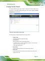
9.1 OVERVIEW................................................................................................................ 97
9.2 FIRMWARE UPDATE .................................................................................................. 97
9.3 IMAGE TRANSFER PROTOCOL ................................................................................... 99
Page vii
iRIS-2400 Web GUI
List of Figures
Figure 1-1: IEI iMAN Web Address Sample..................................................................................4
Figure 1-2: IEI iMAN Web GUI Login Page ...................................................................................5
Figure 1-3: IEI iMAN GUI Interface ................................................................................................6
Figure 2-1: Dashboard Page..........................................................................................................8
Figure 3-1: FRU Information Page ..............................................................................................11
Figure 4-1: Sensor Readings Page .............................................................................................13
Figure 4-2: Live Widget Window .................................................................................................14
Figure 4-3: Event Log Page .........................................................................................................15
Figure 4-4: System and Audit Log Page.....................................................................................16
Figure 4-5: BSOD Screen Page ...................................................................................................17
Figure 5-1: Active Directory Page ...............................................................................................19
Figure 5-2: Advanced Active Directory Settings Page .............................................................21
Figure 5-3: Add Role group Page................................................................................................22
Figure 5-4: DNS Server Settings Page........................................................................................24
Figure 5-5: Event Log Page .........................................................................................................26
Figure 5-6: Images Redirection Page .........................................................................................27
Figure 5-7: Advanced Media Settings Page...............................................................................27
Figure 5-8: Add Image Screen.....................................................................................................29
Figure 5-9: LDAP/E-Directory Settings Page .............................................................................31
Figure 5-10: Advanced LDAP/E-Directory Settings page .........................................................32
Figure 5-11: Add Role Group Page .............................................................................................33
Figure 5-12: Mouse Mode Settings Page....................................................................................35
Figure 5-13: NCSI Settings Page.................................................................................................36
Figure 5-14: Network Settings Page ...........................................................................................37
Figure 5-15: Network Link Configuration Page .........................................................................39
Figure 5-16: NTP Settings Page ..................................................................................................40
Figure 5-17: PAM Ordering Page ................................................................................................41
Figure 5-18: PEF Management - Event Filter .............................................................................43
Figure 5-19: Add Event Filter Entry Page...................................................................................44
Figure 5-20: Alert Policy Tab .......................................................................................................46
Page viii
iRIS-2400 Web GUI
Figure 5-21: Add Alert Policy Entry Page...................................................................................48
Figure 5-22: LAN Destination Page.............................................................................................49
Figure 5-23: Add LAN Destination Entry Page ..........................................................................51
Figure 5-24: RADIUS Settings Page............................................................................................52
Figure 5-25: Remote Session Page.............................................................................................53
Figure 5-26: Services Page..........................................................................................................54
Figure 5-27: Modify Service Screen............................................................................................56
Figure 5-28: SMTP Settings Page ...............................................................................................57
Figure 5-29: SSL Certificate Configuration – Upload SSL........................................................59
Figure 5-30: SSL Certificate Configuration – General SSL ......................................................60
Figure 5-31: SSL Certificate Configuration – View SSL............................................................62
Figure 5-32: System and Audit Log Settings Page ...................................................................63
Figure 5-33: User Management Page..........................................................................................65
Figure 5-34: Add User Page.........................................................................................................66
Figure 5-35: Modify User Page ....................................................................................................68
Figure 5-36: Virtual Media Devices Page ...................................................................................69
Figure 6-1: Java Console Page ...................................................................................................73
Figure 6-2: Virtual Media Wizard Window ..................................................................................78
Figure 6-3: Video Record Setting Window .................................................................................80
Figure 6-4: Power Control and Status Page ..............................................................................83
Figure 6-5: Java SOL Page ..........................................................................................................84
Figure 6-6: BMC Console Redirection BIOS Option .................................................................85
Figure 6-7: BMC Console Redirection Settings BIOS Menu ....................................................85
Figure 6-8: Java SOL ....................................................................................................................86
Figure 6-9: SOL Redirection Window .........................................................................................86
Figure 7-1: Triggers Configuration Page....................................................................................88
Figure 7-2: Recorded Video Page ...............................................................................................89
Figure 8-1: Preserve Configuration Page...................................................................................92
Figure 8-2: Restore Configuration Page ....................................................................................94
Figure 8-3: System Administrator Page .....................................................................................95
Figure 9-1: Firmware Update Page .............................................................................................98
Figure 9-2: Image Transfer Protocol Page .................................................................................99
Page ix
iRIS-2400 Web GUI
Chapter
1
1 Introduction
Page 1
iRIS-2400 Web GUI
1.1 iRIS-2400 Overview
The iRIS-2400 module supports Intelligent Platform Management Interface (IPMI) that
helps lower the overall costs of server management by enabling users to maximize IT
resources, save time and manage multiple systems. The new IPMI 2.0 is designed to
extend customers’ IT capabilities and further improve remote management by introducing
enhanced functions, including:
New authentication and encryption algorithms enhance security for remote
management access
Serial over LAN supports remote interaction with serial-based applications,
BIOS, and operating system
SMBus system interface provides low-pin count connection for low-cost
management controllers
Firmware Firewall supports partitioning and protection of management
between blades in modular system implementations
1.1.1 Hardware Installation
The iRIS-2400 module can be installed into the iRIS module slot on IEI motherboard that
supports IPMI 2.0. Please refer to the motherboard manual for the hardware installation
instruction.
Page 2
iRIS-2400 Web GUI
1.2 IEI iMAN GUI Overview
The IEI iMAN Graphics User Interface (GUI) is designed to manage a client system from a
remote console using standard Internet browsers.
1.2.1 System Requirements
Minimum software requirements for using IEI iMAN GUI are listed below.
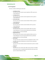
1.2.1.1 Supported Browsers
Internet Explorer 7 and above
Firefox 2.0 and above
Google Chrome 2.0 and above
Safari 3.0 and above
Opera 9.64 and above
1.2.1.2 Supported OS
Windows XP
Windows Vista
Windows 7 32-bt/64-bit
w2k3 - 32 bit
w2k3 - 64 bit
RHEL 4 - 32 bit
RHEL 4 - 64 bit
RHEL 5.4 - 32 bit
RHEL 5.4 - 64 bit
Ubuntu 9.10 LTS – 32
Ubuntu 9.10 LTS – 64
Ubuntu 8.10 -32
Ubuntu 8.10 -64
OpenSuse 11.2 -32
OpenSuse 11.2 -64
FC 9 – 32 and above
FC 9 – 64 and above
MAC -32
Page 3
iRIS-2400 Web GUI
MAC-64
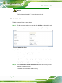
1.2.2 Access the IEI iMAN Web GUI
To initial access to the IEI iMAN web GUI, follow the steps below.
Step 1: Obtain the IP address of the managed system. It is recommended to use the
IPMI Tool to obtain the IP address of the managed system. To use IPMI Tool to
obtain IP address, follow the steps below:
a. Copy the Ipmitool.exe file to a bootable USB flash drive.
b. Insert the USB flash drive to the managed system
c. The managed system boots from the USB flash drive
d. Enter the following command: ipmitool 20 30 02 01 03 00 00
(there is a space between each two-digit number)
e. A serial of number shows. The last four two-digit hexadecimal numbers are
the IP address. Convert the hexadecimal numbers to decimal numbers.
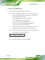
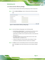
Step 2: On the remote management console, open a web browser. Enter the managed
system IP address in the web browser (Figure 1-1).
Figure 1-1: IEI iMAN Web Address Sample
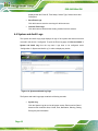
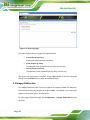
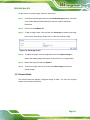
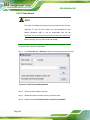
Step 3: The login page appears in the web browser (Figure 1-2).
Page 4
iRIS-2400 Web GUI
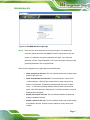
Figure 1-2: IEI iMAN Web GUI Login Page
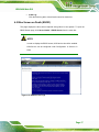
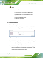
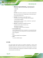
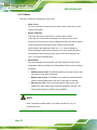
Step 4: Enter the user name and password to login the system. The default login
username and password are both admin. Press the login button to login the
system. It is advised to change the password once login. If you forget the
password, click the “Forgot Password?” link to have the system send the newly
generated password to the configured Email.
Other functions appeared on the login page are described below:
Allow popups from this site: The icon indicates whether the browser allows
popup for this site or not.
Allow file download from this site: For Internet Explorer, choose Tools
->Internet Options ->Security Tab, based on device setup, select among
Internet, Local intranet, Trusted sites and Restricted sites. Click “Custom
Level...”. In the Security Settings window, find and enable File download
option. Click OK to the entire dialog boxes. For all other browsers, accept file
download when prompted.
Enable javascript for this site: The icon indicates whether the javascript
setting is enabled in browser.
Enable cookies for this site: The icon indicates whether the cookies setting
are enabled in browser. Cookies must be enabled in order to access the
website.
Page 5
iRIS-2400 Web GUI
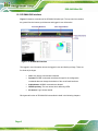
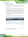
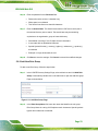
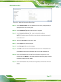
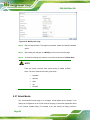
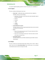
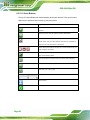
1.2.3 IEI iMAN GUI Interface
Figure 1-3 shows a screenshot of the IEI iMAN GUI after login. The top menu bar contains
the general function buttons, quick buttons and logged-in user information.
Figure 1-3: IEI iMAN GUI Interface
The logged-in user information shows the logged-in user and his/her privilege. There are
five kinds of privileges:
User: Only benign commands are allowed.
Operator: All BMC commands are allowed except for the configuration
commands that can change the behavior of the out-of-hand interfaces.
Administrator: All BMC commands are allowed.
OEM Proprietary: The user access level defined by OEM.
No Access: Login access denied.
Each general function of IEI iMAN GUI is described in detail in the following chapters.
Page 6
iRIS-2400 Web GUI
Chapter
2
2 Dashboard
Page 7
iRIS-2400 Web GUI
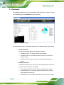
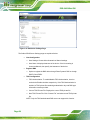
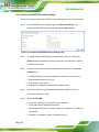
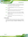
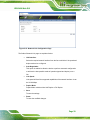
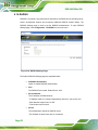
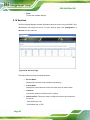
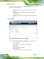
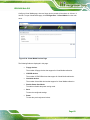
2.1 Dashboard
The Dashboard page gives the overall information about the status of a device. To open
the Dashboard page, click Dashboard from the main menu.
Figure 2-1: Dashboard Page
A brief description about the information displayed in the Dashboard page is given below.
Device Information:
The Device Information displays the following information.
o
o
Firmware Revision: The revision number of the firmware.
Firmware Build Time: This field shows the date and time on which the
firmware is built.
o
EC Revision: The revision number of the embedded controller of the
system
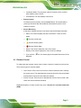
Network Information
The Network Information of the device with the following fields is shown here.
To edit the network Information, click Edit.
o
o
MAC Address: Read only field showing the IP address of the device.
V4 Network Mode: The v4 network mode of the device which could be
either disable, static or DHCP.
o
Page 8
IPv4 Address: The IPv4 address of the device (could be static or DHCP).
iRIS-2400 Web GUI
o
V6 Network Mode: The v6 network mode of the device which could be
either disable, static or DHCP.
o
IPv6 Address: The IPv6 address of the device.
Remote Control
To redirect the host remotely, click the Launch button. This downloads the
jviewer.jnlp file which after downloaded and launched will open the Java
redirection window.
Sensor Monitoring
It lists all the available sensors on the device with the following information.
o
Status: This column displays the state of the device. There are three
states.
o
Denotes normal state
o
Denotes Warning State
o
o
o
o
Denotes Critical State
Sensor: This column states the name of the sensor.
Reading: This column displays the value of sensor readings.
If you click the
displayed.
icon, the sensor page for that particular sensor will be
2.1.1 Remote Control
To redirect the host remotely, launch Java Console or ActiveX Console from this section.
There are two types of consoles related.
Java Console: Click Launch to launch the console redirection and to manage
the remote server. This downloads the jviewer.jnlp file which after downloaded
and launched will open the Java redirection window.
ActiveX Console: Click Launch to download the ActiveX Control, install it and
launch the ActiveX redirection window.
Detailed descriptions of these consoles are given in Section 6.2: Console Redirection
(KVM).
Page 9
iRIS-2400 Web GUI
Chapter
3
3 FRU Information
Page 10
iRIS-2400 Web GUI
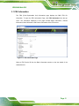
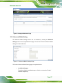
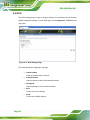
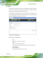
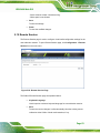
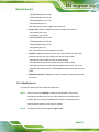
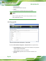
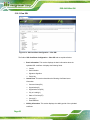
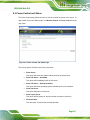
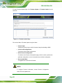
3.1 FRU Information
The FRU (Field Replaceable Unit) Information page displays the BMC FRU file
information. To open the FRU Information Page, click FRU Information from the top
menu. The information displayed in this page includes Basic Information, Chassis
Information, Board Information and Product Information of the FRU device.
Figure 3-1: FRU Information Page
Select a FRU Device ID from the Basic Information section to view the details of the
selected device.
Page 11
iRIS-2400 Web GUI
Chapter
4
4 Server Health
Page 12
iRIS-2400 Web GUI
4.1 Overview
The Server Health consists of five items.
Sensor Readings
Event Log
System and Audit Log
BSOD Screen
BIOS Port80
Each item is described in detail in the following sections.
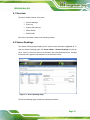
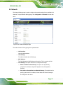
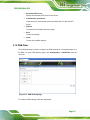
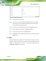
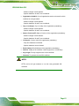
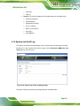
4.2 Sensor Readings
The Sensor Readings page displays all the sensor related information (Figure 4-1). To
open the Sensor Readings page, click Server Health Æ Sensor Readings from the top
menu. Click on a record to show more information about that particular sensor, including
thresholds and a graphical representation of all associated events.
Figure 4-1: Sensor Readings Page
The Sensor Readings page contains the following information.
Page 13
iRIS-2400 Web GUI
4.2.1 Sensor Type
This sensor type drop down menu allows users to select the type of sensor. The list of
sensors with the Sensor Name, Status and Current Reading will be displayed in the list. All
the available sensor details will appear by selecting All Sensors.
Select one particular sensor from the list to view the Thresholds for this sensor on the right
hand side of the screen.
A graphical view of these events (Number of event logs vs. Thresholds) can also be
viewed as shown in Figure 4-1.
4.2.2 Live Widget
Live Widgets is a little gadget, which provides real time information about a particular
sensor. User can track a sensor's behavior over a specific amount of time at specific
intervals. The result will be displayed as a line graph in the widget. The session will not
expire, until the widgets gets a live data of the last widget that is kept opened.
To display Live Widget of the selected sensor, click the ON link on the top right corner of
the Sensor Reading Page. This widget gives a dynamic representation of the readings for
the sensor.
Figure 4-2: Live Widget Window
Page 14
iRIS-2400 Web GUI
4.2.3 View this Event Log
Users can click the View this Event Log button to view the Event Log page for the
selected sensor.
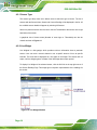
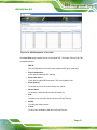
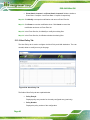
4.3 Event Log
The Event Log page displays the list of event logs occurred by the different sensors on this
device. To open the Event Log page, click Server Health Æ Event Log from the top
menu.
Figure 4-3: Event Log Page
Double click on a record to see the details of that entry. Use the sensor type or sensor
name filter options to view those specific events. Click on any of the column headers to
sort the list of entries.
The Event Log page consists of the following fields.
Event log Category (drop down menu):
there are several event categories in the drop down menu to select.
Filter Type (drop down menu):
select the sensor name filer to view the event for the selected filer. Once the
Event Log Category and Filter Type are selected, the list of events will be
Page 15
iRIS-2400 Web GUI
displayed with the Event ID, Time Stamp, Sensor Type, Sensor Name and
Description
Save Event Logs:
Click this button to save the event logs for all the sensors.
Clear All Event Logs:
Click this button to delete all the existing records for all the sensors.
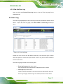
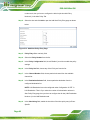
4.4 System and Audit Logs
The System and Audit Logs page displays all logs of the system and audit events that
occurred in this device, if configured. To open the Event Log page, click Server Health Æ
System and Audit Log from the top menu. Logs have to be configured under
“Configuration Æ System and Audit Log” in order to display any entries.
Figure 4-4: System and Audit Log Page
The System and Audit Logs page contains the following two tabs:
System Log:
Click the System Log tab to view all system events. Entries can be filtered
based on their levels like Alert, Critical, Error, Notification, Warning, Debug,
Emergency and Information.
Page 16
iRIS-2400 Web GUI
Audit Log:
Click the Audit Log tab to view all audit events for this device.
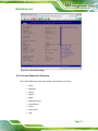
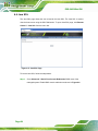
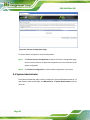
4.5 Blue Screen on Death (BSOD)
This page displays the blue screen captured during failure in host system. To open the
BSOD Screen page, click Server Health Æ BSOD Screen from the menu bar.
NOTE:
In order to display the BSOD screen, KVM service should be enabled.
KVM Service can be configured under Configuration Æ Services Æ
KVM.
Figure 4-5: BSOD Screen Page
Page 17
iRIS-2400 Web GUI
Chapter
5
5 Configuration
Page 18
iRIS-2400 Web GUI
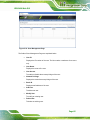
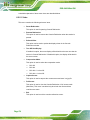
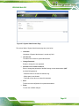
5.1 Overview
The Configuration group allows users to access various configuration settings. Each
configuration setting is described in detail in the following sections.
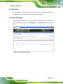
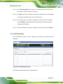
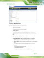
5.2 Active Directory
The Active Directory page allows users to configure Active Directory server settings. To
open Active Directory page, click Configuration Æ Active Directory from the main
menu.
Figure 5-1: Active Directory Page
Page 19
iRIS-2400 Web GUI
NOTE:
An active directory is a directory structure used on Microsoft Windows
based computers and servers to store information and data about
networks and domains. An active directory (sometimes referred to as
an AD) does a variety of functions including the ability to provide
information on objects, helps organize these objects for easy retrieval
and access, allows access by end users and administrators, and allows
the administrator to set security up for the directory.
The fields and buttons on the Active Directory page are explained below.
Advanced Settings:
This option is used to configure Active Directory Advanced Settings. Options
are Enable Active Directory Authentication, User Domain name, and up to
three Domain Controller Server Addresses.
Role Group ID:
The name that identifies the role group in the Active Directory. Role Group
Name is a string of 255 alpha-numeric characters. Special symbols hyphen
and underscore are allowed.
Role Group Name:
The domain where the role group is located. Domain Name is a string of 255
alpha-numeric characters. Special symbols hyphen, underscore and dot are
allowed.
Role Group Privilege:
The level of privilege to assign to this role group.
Add Role Group:
To add a new role group to the device.
Modify Role Group:
To modify that role group. Alternatively, double click on the configured slot.
Delete Role Group:
To delete an existing Role Group.
Page 20
iRIS-2400 Web GUI
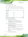
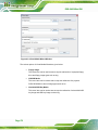
5.2.1 Advanced Active Directory Settings
To enter the details in Advanced Active Directory Settings page, follow the steps below:
Step 1: Click on Advanced Settings to open the Advanced Active Directory Settings
page.
Figure 5-2: Advanced Active Directory Settings Page
Step 2: In the Active Directory Settings page, enter the following details.
Active Directory Authentication: To enable/disable Active Directory, check
or uncheck the Enable checkbox respectively. If the Active Directory
Authentication is enabled, enter the required information to access the Active
Directory server.
User Domain Name: Specify the Domain Name for the user in the User
Domain Name field. e.g. MyDomain.com
Configure IP addresses in Domain Controller Server Address1, Domain
Controller Server Address2 and Domain Controller Server Address3
Step 3: Click Save to save the entered settings and return to Active Directory Settings
page. Click Cancel to cancel the entry and return to Active Directory Settings
page.
Page 21
iRIS-2400 Web GUI
NOTE:
IP address of Active Directory server:
At least one Domain Controller Server Address must be
configured.
IP Address made of four numbers separated by dots as in
"xxx.xxx.xxx.xxx".
Each number ranges from 0 to 255.
First number must not be 0.
5.2.2 Add New Role Group
To add a new Role Group, follow the steps below.
Step 1: In the Active Directory Settings page, select a blank row and click Add Role
Group to open the Add Role Group page as shown in Figure 5-3.
Figure 5-3: Add Role group Page
Step 2: In the Role Group Name field, enter the name that identifies the role group in
the Active Directory. Role Group Name is a string of 255 alpha-numeric
characters. Special symbols hyphen and underscore are allowed.
Step 3: In the Role Group Domain filed, enter the domain where the role group is
located. Domain Name is a string of 255 alpha-numeric characters. Special
symbols hyphen, underscore and dot are allowed.
Page 22
iRIS-2400 Web GUI
Step 4: In the Role Group Privilege field, enter the level of privilege to assign to this
role group.
Step 5: Click Add to save the new role group and return to the Role Group List. Click
Cancel to cancel the settings and return to the Role Group List.
Step 6: To Modify Role Group, select the row that you wish to modify and click Modify
Role Group. Make the necessary changes and click Save.
Step 7: To Delete a Role Group, select the row that you wish to delete and click Delete
Role Group.
5.3 DNS
The DNS Server settings page is used to manage the DNS settings of a device. The
Domain Name System (DNS) is a distributed hierarchical naming system for computers,
services, or any resource connected to the Internet or a private network. It associates
information with domain names assigned to each of the participants. Most importantly, it
translates domain names meaningful to humans into the numerical (binary) identifiers
associated with networking equipment for the purpose of locating and addressing these
devices worldwide. To open DNS Server Settings page, click Configuration Æ DNS from
the main menu.
Page 23
iRIS-2400 Web GUI
Figure 5-4: DNS Server Settings Page
The fields of DNS Server Settings page are explained below.
Host Configuration
o
o
Host Settings: Choose either Automatic or Manual settings.
Host Name: It displays hostname of the device. If the Host setting is
chosen as Manual, then specify the hostname of the device.
Register BMC
o
Option to register the BMC either through Direct Dynamic DNS or through
DHCP Client FQDN.
TSIG Configuration
o
TSIG Authentication: To enable/disable TSIG Authentication, check or
uncheck the Enable checkbox respectively. If the TSIG Authentication is
enabled, a TSIG private file containing authentication key and DNS type
information must be provided.
o
o
Current TSIG Private File: Displays the current TSIG private file.
New TSIG Private File: Click “Choose File” and select a new TSIG private
file.
NOTE: Only the TSIG authenticated DNS server can support this function.
Page 24
iRIS-2400 Web GUI
Domain Name Configuration
o
Domain Settings: It lists the option for domain interface as Manual, v4 or
v6 for multi LAN channels. Note: If the user chooses DHCP, then select
v4 or v6 for DHCP servers.
o
Domain Name: It displays the domain name of the device. If the Domain
setting is chosen as Manual, then specify the domain name of the device.
If you chose Automatic, the Domain Name cannot be configured as it will
be done automatically. The field will be disabled.
Domain Name Server Configuration
o
DNS Server Settings: It lists the option for DNS settings for the device,
Manual and available LAN interfaces.
o
IP Priority: Select either using IPv4 address or IPv6 address as the
priority option
o
Preferred DNS Server: The DNS (Domain Name System) server address
to be configured to the device.
- IP Address made of 4 numbers separated by dots as in
"xxx.xxx.xxx.xxx".
- Each number ranges from 0 to 255.
- First number must not be 0.
After DNS configuration is complete, click the Save button to save the entered changes.
Click the Reset button to reset the entered changes.
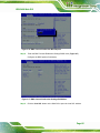
5.4 System Event Log
The System Event Log page is used to configure the SEL type, that is Linear SEL or
Circular SEL. Linear SEL type will store the System Event log linearly up to its SEL
Repository size and SEL will be discarded if the SEL Repository is full. Circular SEL type
will store the System Event log linearly up to its SEL Repository size and override the SEL
entry if the SEL Repository is full.
To open System Event log page, click Configuration Æ Event Log from the menu bar.
Page 25
iRIS-2400 Web GUI
Figure 5-5: Event Log Page
The fields of System Event Log page are explained below.
Current Event Log Policy:
Displays the configured Event Log Policy.
Linear Event Log Policy:
To enable the Linear System Event Log Policy for Event Log.
Circular Event Log Policy:
To enable the Circular System Event Log Policy for Event Log.
After Event Log configuration is complete, click the Save button to save the configured
settings. Click the Reset button to reset the modified changes.
5.5 Images Redirection
The Images Redirection page is used to configure the images into BMC for redirection.
This can be done either by uploading an image into BMC, Local Media or by mounting the
image from the remote system, Remote Media.
To open Images Redirection page, click Configuration Æ Images Redirection from the
menu bar.
Page 26
iRIS-2400 Web GUI
Figure 5-6: Images Redirection Page
5.5.1 Advanced Media Setting
The Advanced Media Settings screen can be accessed by clicking the Advanced
Settings button on the Image Redirection page. The user can enter the Advanced Media
Settings for media redirection.
Figure 5-7: Advanced Media Settings Page
The fields of Advanced Media Settings page are explained below.
Local Media Support:
To enable or disable Local Media support. Check or uncheck the “Enable”
checkbox respectively.
Page 27
iRIS-2400 Web GUI
Remote Media Support:
To enable or disable Remote Media support. Check or uncheck the “Enable”
checkbox respectively. Both local and remote media support cannot be
enabled at a time
Server Address:
Server address of the remote media images is stored.
Source Path:
Source path of the remote media images is stored.
Share Type:
Share Type of the remote media server either NFS or Samba (CIFS).
Username, Password and Domain Name:
If share Type is Samba (CIFS), then user credentials to authenticate the
server.
Click the Save button to save the configured settings. Click the Cancel button to cancel
the modifications and return to Images Redirection list.
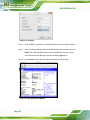
5.5.2 Local Media
The Local Media tab displays the list of available images in the local media on BMC. The
user can replace or add new images from here. To configure the image, the user needs to
enable Local Media support under Images Redirection Æ Advanced Settings. Once
enabled, the user can add the images and the added images will be redirected to the host
machine
NOTE:
To replace or add an image, the user must have Administrator
Privileges.
Only one image can be uploaded for each image type. If the existing
image and uploading image name is same, then a message is shown
“Image already exists”.
In Local Media redirection, the maximum upload size is 8MB.
Page 28
iRIS-2400 Web GUI
To add, remove or modify images, follow the steps below.
Step 1: Click Advanced Setting and make sure Local Media Support option is enabled.
If not, disable Remote Media Redirection and then enable Local Media
Redirection.
Step 2: Click on the Local Media Tab.
Step 3: To add an image, select a free slot and click Add Image to upload a new image
to the device. Alternatively, double click on a free slot to add an image.
Figure 5-8: Add Image Screen
Step 4: To replace an image, select a configured slot and click Replace Image to
replace the existing image. Alternatively, double click on the configured slot.
Step 5: Browse the image File and click Replace
Step 6: To delete an image, select a record and click Delete Image to delete the
selected image.
5.5.3 Remote Media
The Remote Media tab displays configured images on BMC. The user can configure
images of the remote media server.
Page 29
iRIS-2400 Web GUI
NOTE:
Only one image can be configured for each image type.
To configure the image, the user needs to enable Remote Media
support using 'Advanced Settings'.
To add or replace an image, the user must have Administrator
Privileges.
Free slots are denoted by "~".
To Start/Stop Redirection, follow the steps below.
Step 1: To Start/Stop Redirection and configure remote media images, click Advanced
Setting and make sure Remote Media Support option is enabled. If not, disable
Local Media Redirection and then enable Remote Media Redirection.
Step 2: Select a configured slot and click Start Redirection to start the remote media
redirection. It is a toggle button, if the image is successfully redirected, then click
Stop Redirection button to stop the remote media redirection.
Step 3: To add an image, select a free slot and click Add Image to configure a new
image to the device. Alternatively, double click on a free slot to add an image.
Step 4: To replace an image, select a configured slot and click Replace Image to
replace the existing image. Alternatively, double click on the configured slot.
Step 5: To delete an image, select the desired image to be deleted and click Delete
Image.
NOTE:
Redirection needs to be stopped to replace or delete the image.
Page 30
iRIS-2400 Web GUI
5.6 LDAP/E-Directory Settings
The Lightweight Directory Access Protocol (LDAP)/E-Directory Settings is an application
protocol for querying and modifying data of directory services implemented in Internet
Protocol (IP) networks.
In IEI iMAN GUI, LDAP is an Internet protocol that the iRIS-2400 module can use to
authenticate users. If there is an LDAP server configured on the network, the user can use
it as an easy way to add, manage and authenticate the iRIS-2400 module users. This is
done by passing login requests to the LDAP Server. This means that there is no need to
define an additional authentication mechanism, when using the iRIS-2400 module. Since
the existing LDAP Server keeps an authentication centralized, the user will always know
who is accessing the network resources and can easily define the user or group-based
policies to control access.
To open LDAP Settings page, click Configuration Æ LDAP/E-Directory Settings from
the main menu.
Figure 5-9: LDAP/E-Directory Settings Page
Page 31
iRIS-2400 Web GUI
5.6.1 Advanced LDAP/E-Directory Settings
To enter the details in Advanced LDAP/E-Directory Settings page, follow the steps below.
Step 1: In the LDAP/E-Directory Settings Page, click Advanced Settings. The
Advanced LDAP/E-Directory Settings page appears (Figure 5-10).
Figure 5-10: Advanced LDAP/E-Directory Settings page
Step 2: To enable/disable LDAP/E-Directory Authentication, check or uncheck the
Enable checkbox respectively. During login prompt, use username to login as
an ldap Group member.
Step 3: Follow the rules below to enter the IP address of LDAP server in the Server
Address field.
IP Address made of 4 numbers separated by dots as in 'xxx.xxx.xxx.xxx'.
Each Number ranges from 0 to 255.
First Number must not be 0.
Supports IPv4 Address format and IPv6 Address format.
Step 4: Specify the LDAP Port in the Port field. Default Port is 389. For Secure
connection, default port is 636.
Step 5: Specify the Bind DN:
Bind DN is a string of 4 to 64 alpha-numeric characters.
It must start with an alphabetical character.
Special Symbols like dot(.), comma(,), hyphen(-), underscore(_), equal-to(=)
are allowed.
Page 32
Example: cn=manager,ou=login, dc=domain,dc=com
iRIS-2400 Web GUI
Step 6: Enter the password in the Password field.
Password must be at least 1 character long.
White space is not allowed.
This field will not allow more than 48 characters.
Step 7: Enter the Search Base. The Search base tells the LDAP server which part of
the external directory tree to search. The search base may be something
equivalent to the organization, group of external directory.
Searchbase is a string of 4 to 63 alpha-numeric characters.
It must start with an alphabetical character.
Special Symbols like dot(.), comma(,), hyphen(-), underscore(_), equal-to(=)
are allowed.
Example: ou=login,dc=domain,dc=com
Step 8: Click Save to save the settings. Click Cancel to cancel the modified changes.
5.6.2 Add New Role Group
To add a new Role Group, follow the steps below.
Step 1: In the LDAP/E-Directory Settings Page, select a blank row and click Add Role
Group or alternatively double click on the blank row to open the Add Role group
Page as shown below.
Figure 5-11: Add Role Group Page
Step 2: In the Role Group Name field, enter the name that identifies the role group.
Role Group Name is a string of 255 alpha-numeric characters. Special symbols
hyphen and underscore are allowed.
Page 33
iRIS-2400 Web GUI
Step 3: In the Role Group Search Base field, enter the path from where the role group
is located to Base DN. Search Base is a string of 255 alpha-numeric characters.
Special symbols hyphen, underscore and dot are allowed.
Step 4: In the Role Group Privilege field, enter the level of privilege to assign to this
role group.
Step 5: Click Add to save the new role group and return to the Role Group List. Click
Cancel to cancel the settings and return to the Role Group List.
Step 6: To Modify Role Group, select the row that you wish to modify and click Modify
Role Group or double click the row that you wish to modify. Make the necessary
changes and click Save.
Step 7: To Delete a Role Group, select the row that you wish to delete. Then, click
Delete Role Group.
5.7 Mouse Mode
In IEI iMAN GUI, Redirection Console handles mouse emulation from local window to
remote screen in either of two methods. User has to be an Administrator to configure this
option. To open Mouse Mode page, click Configuration Æ Mouse Mode from the main
menu.
Page 34
iRIS-2400 Web GUI
Figure 5-12: Mouse Mode Settings Page
The fields of Mouse Mode Settings page are explained below.
Absolute Mode:
The absolute position of the local mouse is sent to the server. Applicable for
all Windows versions, versions above RHEL6, and versions above FC14
Relative Mode:
Relative mode sends the calculated relative mouse position displacement to
the server. Applicable for all Linux versions, versions less than RHEL6, and
versions less than FC14
Other Mode:
To have the calculated displacement from the local mouse in the center
position sent to the server. Recommended for SLES-11 OS Installation
Save:
To save the changes made.
Reset:
To Reset the modified changes.
Page 35
iRIS-2400 Web GUI
5.8 NCSI
The NCSI Settings page is used to configure Network Communication Service Interface
(NCSI) configuration settings. To open NCSI page, click Configuration Æ NCSI from the
main menu.
Figure 5-13: NCSI Settings Page
The following fields are displayed in this page
Interface Name:
It lists the interface name in list box.
Channel Number:
Lists the channel number of the selected interface.
Package ID:
Lists the package id of the selected interface.
Save:
To save the current changes.
Reset:
To reset the modified changes.
Page 36
iRIS-2400 Web GUI
5.9 Network
The Network Settings page is used to configure the network settings for the available LAN
channels. To open Network Settings page, click Configuration Æ Network from the main
menu.
Figure 5-14: Network Settings Page
The fields of Network Settings page are explained below.
LAN Interface:
Lists the LAN interfaces.
LAN Settings:
To enable or disable the LAN Settings.
MAC Address:
This field displays the MAC Address of the device. This is a read only field.
IPv4 Settings: This option lists the IPv4 configuration settings.
o
Obtain IP Address automatically: This option is to dynamically
configure IPv4 address using DHCP (Dynamic Host Configuration
Protocol).
o
IPv4 Address, Subnet Mask, and Default Gateway: These fields are for
specifying the static IPv4 address, Subnet Mask and Default Gateway to
be configured to the device.
Page 37
iRIS-2400 Web GUI
- IP Address made of 4 numbers separated by dots as in
"xxx.xxx.xxx.xxx".
- Each Number ranges from 0 to 255.
- First Number must not be 0.
IPv6 Configuration: This option lists the following IPv6 configuration settings.
o
IPv6 Settings: This option is to enable/disable the IPv6 settings in the
device.
o
Obtain an IPv6 address automatically: This option is to dynamically
configure IPv6 address using DHCP (Dynamic Host Configuration
Protocol).
o
IPv6 Address: To specify a static IPv6 address to be configured to the
device. Eg: 2004::2010
o
Subnet Prefix length: To specify the subnet prefix length for the IPv6
settings. Value ranges from 0 to 128.
o
Default Gateway: Specify v6 default gateway for the IPv6 settings.
VLAN Configuration: It lists the VLAN configuration settings.
o
VLAN Settings: To enable/disable the VLAN support for selected
interface.
o
VLAN ID: The Identification for VLAN configuration. Value ranges from 1
to 4095.
o
VLAN Priority: The priority for VLAN configuration. Value ranges from 1
to 7. Seven is the highest priority for VLAN.
Save:
To save the entries.
Reset:
To Reset the modified changes.
5.10 Network Link
The Network Link Configuration page is used to configure the network link configuration
for available network interfaces. To open Network Link page, click Configuration Æ
Network Link from the menu bar.
Page 38
iRIS-2400 Web GUI
Figure 5-15: Network Link Configuration Page
The fields of Network Link page are explained below.
LAN Interface:
Select the required network interface from the list to which the Link speed and
duplex mode to be configured.
Auto Negotiation:
This option is enabled to allow the device to perform automatic configuration
to achieve the best possible mode of operation (speed and duplex) over a
link.
Link Speed:
Link speed will list all the supported capabilities of the network interface. It can
be 10/100 Mbps.
Duplex Mode:
Duplex Mode could be either Half Duplex or Full Duplex.
Save:
To save the settings.
Reset:
To reset the modified changes.
Page 39
iRIS-2400 Web GUI
5.11 NTP
The Network Time Protocol (NTP) is a protocol for synchronizing the clocks of computer
systems over packet-switched, variable-latency data networks. It is designed particularly
to resist the effects of variable latency by using a jitter buffer.
In IEI iMAN GUI, this page displays the device current date and time settings. It can be
used to configure Date, Time or NTP server settings for the device. To open NTP Settings
page, click Configuration Æ NTP from the main menu.
Figure 5-16: NTP Settings Page
The fields of NTP are explained below.
Date:
To specify the current date of the device
Time:
Specify the current Time for the device.
Note: As Year 2038 Problem exists, Date and Time should be configured
within the range.
Primary NTP Server:
Specify the primary NTP Server for the device.
Page 40
iRIS-2400 Web GUI
Secondary NTP Server:
Specify the secondary NTP Server for the device.
Automatically synchronize:
Check the box to automatically synchronize Date and Time with the NTP
Server.
Refresh:
To reload the current date and time settings.
Save:
To save the settings.
Reset:
To reset the modified changes.
5.12 PAM Order
The PAM Order page is used to configure the PAM ordering for user authentication in to
the BMC. To open PAM Ordering page, click Configuration Æ PAM Order from the
menu bar.
Figure 5-17: PAM Ordering Page
To configure PAM ordering, follow the steps below.
Page 41
iRIS-2400 Web GUI
Step 1: Select the required PAM module and click
(up) button to move the
module one step before the existing module.
Step 2: Select the required PAM module and click
(down) button to move the
module one step after the existing module.
Step 3: Click Save to save any changes made.
Step 4: Click Reset to reset the modified changes.
5.13 PEF
Platform Event Filtering (PEF) provides a mechanism for configuring the BMC to take
selected actions on event messages that it receives or has internally generated. These
actions include operations such as system power-off, system reset, as well as triggering
the generation of an alert. To open PEF Management Settings page, click Configurations
Æ PEF from the main menu.
The PEF Management is used to configure the following
Event Filter
Alert Policy
LAN Destination
Each tab is explained in detail in the following sections.
5.13.1 Event Filter Tab
A PEF implementation is recommended to provide at least 16 entries in the event filter
table. A subset of these entries should be pre-configured for common system failure
events, such as over-temperature, power system failure, fan failure events, etc.
Remaining entries can be made available for ‘OEM’ or System Management Software
configured events. Note that individual entries can be tagged as being reserved for system
use - so this ratio of pre-configured entries to run-time configurable entries can be
reallocated if necessary.
Page 42
iRIS-2400 Web GUI
Figure 5-18: PEF Management - Event Filter
The Event Filter page contains the list of configured PEF. The fields of Event Filter Tab
are explained below.
PEF ID:
This field displays the ID for the newly configured PEF entry (read only).
Filter Configuration:
Check box to enable the PEF settings.
Event Filter Action:
Check box to enable PEF Alert action. This is a mandatory field.
Event Severity:
To choose any one of the event severity from the list.
Sensor Name:
To choose the particular sensor from the sensor list.
Add:
To add the new event filter entry and return to Event Filter list.
Modify:
To modify the existing entries.
Cancel:
To cancel the modification and return to Event Filter list.
Page 43
iRIS-2400 Web GUI
5.13.1.1 Add Event Filter Entry
To add an event filter entry, follow the steps below.
Step 1: Click the Event Filter Tab to configure the event filters in the available slots.
Step 2: Select a free slot and click Add to open the Add event Filter Entry page (Figure
5-19).
Figure 5-19: Add Event Filter Entry Page
Step 3: In the Event Filter Configuration section,
PEF ID displays the ID for configured PEF entry (read only).
In Filter Configuration, check the box to enable the PEF settings.
In Event Severity, select any one of the Event severity from the list.
Step 4: In the Filter Action configuration section,
Event Filter Action is a mandatory field and checked by default, which
enable PEF Alert action (read only).
Select any one of the Power Action either Power down, Power reset or
Power cycle from the drop down list
Choose any one of the configured Alert Policy Number from the drop down
list.
NOTE: Alert Policy has to be configured under Configuration Æ PEF-Æ
Alert Policy.
Step 5: In the Generator ID configuration section,
Page 44
iRIS-2400 Web GUI
Check Generator ID Data option to fill the Generator ID with raw data.
Generator ID 1 field is used to give raw generator ID1 data value.
Generator ID 2 field is used to give raw generator ID2 data value.
NOTE: In RAW data field, specify hexadecimal value prefix with '0x'.
In the Event Generator field, choose the event generator as Slave type - if
event was generated from IPMB. Otherwise as Software type - if event was
generated from system software.
In the Slave Address/Software ID field, specify corresponding I2C Slave
Address or System Software ID.
Choose the particular channel number that event message was received
over. Or choose “0” if the event message was received via the system
interface, primary IPMB, or internally generated by the BMC.
Choose the corresponding IPMB device LUN if event generated by IPMB.
Step 6: In the Sensor configuration section,
Select the type of sensor that will trigger the event filter action.
In the Sensor Name field, choose the particular sensor from the sensor list.
Choose event option to be either All Events or Sensor Specific Events.
Step 7: In the Event Data configuration section,
Event Trigger field is used to give Event/Reading type value. Value ranges
from 1 to 255.
Event Data 1 AND Mask field is used to indicate wildcarded or compared bits.
Value ranges from 0 to 255.
Event Data 1 Compare 1 and Event Data 1 Compare 2 fields are used to
indicate whether each bit position's comparison is an exact comparison or not.
Value ranges from 0 to 255.
Step 8: In the Event Data 2 configuration section,
Event Data 2 AND Mask field is similar to Event Data 1 AND Mask.
Event Data 2 Compare 1 and Event Data 2 Compare 2 fields are similar to
Event Data 1 Compare 1 and Event Data 1 Compare 2 respectively.
Step 9: In the Event Data 3 configuration section,
Event Data 3 AND Mask field is similar to Event Data 1 AND Mask.
Page 45
iRIS-2400 Web GUI
Event Data 3 Compare 1 and Event Data 3 Compare 2 fields are similar to
Event Data 1 Compare 1 and Event Data 1 Compare 2 respectively.
Step 10: Click Modify to accept the modification and return to Event Filter list.
Step 11: Click Reset to reset the modification done. Click Cancel to cancel the
modification and return to Event Filter list.
Step 12: In the Event filter list, click Modify to modify the existing filter.
Step 13: In the Event filter list, click Delete to delete the existing filter.
5.13.2 Alert Policy Tab
The Alert Policy tab is used to configure the Alert Policy and LAN destination. The user
can add, delete or modify an entry in this page.
Figure 5-20: Alert Policy Tab
The fields of Alert Policy tab are explained below.
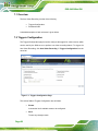
Policy Entry #:
Displays policy entry number for the newly configured entry (read only).
Policy Number:
Displays the policy number of the configuration.
Page 46
iRIS-2400 Web GUI
Policy Configuration:
To enable or disable the policy settings.
Policy Set:
To choose any one of the Policy set values from the list.
o
o
0 - Always send alert to this destination.
1 - If alert to previous destination was successful, do not send alert to this
destination. Proceed to next entry in this policy set.
o
2 - If alert to previous destination was successful, do not send alert to this
destination. Do not process any more entries in this policy set.
o
3 - If alert to previous destination was successful, do not send alert to this
destination. Proceed to next entry in this policy set that is to a different
channel.
o
4 - If alert to previous destination was successful, do not send alert to this
destination. Proceed to next entry in this policy set that is to a different
destination type.
Channel Number:
To choose a particular channel from the available channel list.
Destination Selector:
To choose a particular destination from the configured destination list.
NOTE: LAN Destination has to be configured under Configuration Æ PEFÆ
LAN Destination.
Add:
To save the new alert policy and return to Alert Policy list.
Modify:
To modify the existing entries.
Cancel:
To cancel the modification and return to Alert Policy list.
5.13.2.1 Add Alert Policy Entry
To add an alert policy entry, follow the steps below.
Step 1: In the Alert Policy tab, select the slot for which you have to configure the Alert
Policy. That is, in the Event Filter Entry page, if you have chosen Alert Policy
Page 47
iRIS-2400 Web GUI
number as 4, then you have to configure the 4th slot (the slot with Policy
Number 4) in the Alert Policy Tab.
Step 2: Select the slot and click Add to open the Add Alert Policy Entry page as shown
below.
Figure 5-21: Add Alert Policy Entry Page
Step 3: Policy Entry # is a read only field.
Step 4: Select the Policy Number from the list.
Step 5: In the Policy Configuration field, check Enable if you wish to enable the policy
settings.
Step 6: In the Policy Set field, choose any of the Policy set from the list.
Step 7: In the Channel Number field, choose particular channel from the available
channel list.
Step 8: In the Destination Selector field, choose particular destination from the
configured destination list.
NOTE: LAN Destination has to be configured under Configuration Æ PEF Æ
LAN Destination. That is if you select the number 4 for destination selector in
Alert Policy Entry page, then you have to configure the 4th slot (LAN Destination
Number 4) in the LAN Destination tab.
Step 9: In the Alert String field, enable the check box if the Alert policy entry is Event
Specific.
Page 48
iRIS-2400 Web GUI
Step 10: In the Alert String Key field, choose any one value that is used to look up the
Alert String to send for this Alert Policy entry.
Step 11: Click Add to save the new alert policy and return to Alert Policy list. Click Cancel
to cancel the modification and return to Alert Policy list.
Step 12: In the Alert Policy list, to modify a configuration, select the slot to be modified
and click Modify. In the Modify Alert Policy Entry Page, make the necessary
changes and click Modify.
Step 13: In the Alert Policy list, to delete a configuration, select the slot and click Delete.
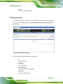
5.13.3 LAN Destination
The LAN Destination page is used to configure the Event filter, Alert Policy and LAN
destination.
Figure 5-22: LAN Destination Page
The fields of LAN Destination tab are explained below.
Page 49
iRIS-2400 Web GUI
LAN Destination:
Displays destination number for the newly configured entry (read only).
Destination Type:
Destination type can be either an SNMP Trap or an Email alert. For Email
alerts, the 3 fields - destination Email address, subject and body of the
message needs to be filled. The SMTP server information also has to be
added under Configuration Æ SMTP. For SNMP Trap, only the destination IP
address has to be filled.
Destination Address:
If Destination type is SNMP Trap, then enter the IP address of the system that
will receive the alert. Destination address will support the following:
o
o
- IPv4 address format.
- IPv6 address format.
Send Test Alert:
To send sample alert to configured destination. Test alert can sent only with
enabled SMTP configuration. SMTP support can be enabled under
Configuration Æ SMTP.
Add: To save the new LAN destination and return to LAN destination list.
Cancel: To cancel the modification and return to LAN destination list.
5.13.3.1 Configure LAN Destination
To configure LAN Destination, follow the steps below.
Step 1: In the LAN Destination tab, choose the slot to be configured. This should be the
same slot that you have selected in the Alert Policy Entry- Destination Selector
field. That is if you have chosen the Destination Selector as 4 in the Alert Policy
Entry page of Alert Policy Tab, then you have to configure the 4th slot of LAN
Destination Page.
Step 2: Select the slot and click Add. This opens the Add LAN Destination entry ().
Page 50
iRIS-2400 Web GUI
Figure 5-23: Add LAN Destination Entry Page
Step 3: In the LAN Destination field, the destination for the newly configured entry is
displayed and this is a read only field.
Step 4: In the Destination Type field, select the one of the types.
Step 5: In the Destination Address field, enter the destination address.
NOTE: If Destination type is Email Alert, then give the email address that will
receive the email.
Step 6: Select the User Name from the list of users.
Step 7: In the Subject field, enter the subject.
Step 8: In the Message field, enter the message.
Step 9: Click Add to save the new LAN destination and return to LAN destination list.
Click Cancel to cancel the modification and return to LAN destination list.
Step 10: In the LAN Destination tab, to modify a configuration, select the row to be
modified and click Modify. In the Modify LAN Destination Entry page, make the
necessary changes and click Modify.
Step 11: In the LAN Destination Tab, to delete a configuration, select the slot and click
Delete.
Page 51
iRIS-2400 Web GUI
5.14 RADIUS
RADIUS is a modular, high performance and feature-rich RADIUS suite including server,
clients, development libraries and numerous additional RADIUS related utilities. The
RADIUS Settings page is used to set the RADIUS Authentication. To open RADIUS
Settings page, click Configuration Æ RADIUS from the main menu.
Figure 5-24: RADIUS Settings Page
The fields of RADIUS Settings page are explained below.
RADIUS Authentication:
Option to enable RADIUS authentication.
Port:
The RADIUS Port number. Default Port is 1812.
Server Address:
The IP address of RADIUS server.
- IP Address made of 4 numbers separated by dots as in "xxx.xxx.xxx.xxx".
- Each Number ranges from 0 to 255.
- First Number must not be 0.
Secret:
The Authentication Secret for RADIUS server.
-This field will not allow more than 31 characters.
Page 52
iRIS-2400 Web GUI
- Secret must be at least 4 characters long.
- White space is not allowed.
Save:
To save the settings.
Reset:
To reset the modified changes.
5.15 Remote Session
The Remote Session page is used to configure virtual media configuration settings for the
next redirection session. To open Remote Session page, click Configuration Æ Remote
Session from the main menu.
Figure 5-25: Remote Session Page
The fields of Remote Session page are explained below.
Keyboard Language:
Use this option to select a keyboard language for next redirection session.
Save:
To save the current changes. It will automatically close the existing remote
redirection either KVM or Virtual media sessions, if any.
Page 53
iRIS-2400 Web GUI
Reset:
To reset the modified changes.
5.16 Services
The Services page displays the basic information about services running in the BMC. Only
Administrator can modify the service. To open Services page, click Configuration Æ
Services from the menu bar.
Figure 5-26: Services Page
The fields of Services Page are explained below.
Service Name:
Displays service name of the selected slot (read-only).
Current State:
Displays the current status of the service, either active or inactive state.
Interfaces:
It shows the interface in which service is running.
Nonsecure Port: This port is used to configure non secure port number for
the service.
- Web default port is 80
- KVM default port is 7578
Page 54
iRIS-2400 Web GUI
- CD Media default port is 5120
- FD Media default port is 5122
- HD Media default port is 5123
- Telnet default port is 23
Note: SSH service will not support non secure port.
Secure Port: Used to configure secure port number for the service.
- Web default port is 443
- KVM default port is 7582
- CD Media default port is 5124
- FD Media default port is 5126
- HD Media default port is 5127
- SSH default port is 22
Note: Telnet service will not support secure port.
Timeout: Displays the session timeout value of the service. For web, SSH
and telnet service, user can configure the session timeout value.
- Web timeout value ranges from 300 to 1800 seconds.
- SSH and Telnet timeout value ranges from 30 to 1800 seconds.
- SSH and telnet service will be using the shared timeout value. If the user
configures SSH timeout value, it will be applied to telnet service also and vice
versa.
Maximum Sessions: Displays the maximum number of allowed sessions for
the service.
5.16.1 Modify Service
To modify the existing services, follow the steps below.
Step 1: Select a slot and click Modify to modify the configuration of the service.
Alternatively, double click on the slot. Note: Whenever the configuration is
modified, the service will be restarted automatically. User has to close the
existing opened session for the service if needed.
Step 2: The Modify Service screen appears (Figure 5-27).
Page 55
iRIS-2400 Web GUI
Figure 5-27: Modify Service Screen
Step 3: Service Name is a read only field
Step 4: Activate the Current State by enabling the Activate check box. The Interface,
Nonsecure port, Secure port, Maximum Sessions and Active Sessions will not
be active unless the current state is active.
Step 5: Choose any one of the available interfaces from the Interface dropdown list.
Step 6: Enter the Nonsecure port number in the Nonsecure Port field.
Step 7: Enter the Secure Port Number in the Secure Port field.
Step 8: Click Modify to save the entered changes and return to the Services Page. Click
Cancel to exit.
5.17 SMTP
Simple Mail Transfer Protocol (SMTP) is an Internet standard for electronic mail (e-mail)
transmission across Internet Protocol (IP) networks. Use the SMTP Settings page to
configure the SMTP settings of the device. To open SMTP Settings page, click
Configuration Æ SMTP from the main menu.
Page 56
iRIS-2400 Web GUI
Figure 5-28: SMTP Settings Page
The fields of SMTP Settings Page are explained below.
LAN Channel Number:
Displays the list of LAN channels available
Sender Address:
A valid 'Sender Address' to indicate the BMC, whenever email is sent.
Machine Name: The 'Machine Name' of the BMC, from where the email is
sent.
- Machine Name is a string of maximum 15 alpha-numeric characters.
- Space, special characters are not allowed.
Primary SMTP Server: Lists the Primary SMTP Server configuration.
o
o
SMTP Support: To enable/disable SMTP support for the BMC.
Server Address: The 'IP address' of the SMTP Server. It is a mandatory
field.
- IP Address made of 4 numbers separated by dots as in "xxx.xxx.
xxx.xxx".
- Each Number ranges from 0 to 255.
- First Number must not be 0.
- Supports IPv4 Address format and IPv6 Address format.
Page 57
iRIS-2400 Web GUI
o
SMTP Server requires Authentication: To enable/disable SMTP
Authentication. SMTP Server Authentication Types supported are:
- CRAM-MD5
- LOGIN
- PLAIN
If the SMTP server does not support any one of the above authentication
types, the user will get an error message stating, "Authentication type is
not supported by SMTP Server"
o
Username: The username to access SMTP Accounts.
- User Name can be of length 4 to 64 alpha-numeric characters.
- It must start with an alphabet.
- Special characters ','(comma), ':'(colon), ';'(semicolon), ' '(space) and
'\'(backslash) are not allowed.
o
Password: The password for the SMTP User Account.
- Password must be at least 4 characters long.
- White space is not allowed.
- This field will not allow more than 64 characters.
Secondary SMTP Server:
It lists the Secondary SMTP Server configuration. It is an optional field. If the
Primary SMTP server is not working fine, then it tries with Secondary SMTP
Server configuration.
Save:
To save the new SMTP server configuration.
Reset:
To reset the modified changes.
5.18 SSL
The Secure Socket Layer protocol was created by Netscape to ensure secure
transactions between web servers and browsers. The protocol uses a third party, a
Certificate Authority (CA), to identify one end or both end of the transactions. The user can
use the SSL Certificate page to configure SSL certificate into the BMC, then the device
can be accessed in a secured mode.
Page 58
iRIS-2400 Web GUI
To open SSL Certificate Configuration page, click Configuration Æ SSL from the menu
bar. There are three tabs in this page.
Upload SSL option is used to upload the certificate and private key file into
the BMC.
Generate SSL option is used to generate the SSL certificate based on
configuration details.
View SSL option is used to view the uploaded SSL certificate in readable
format.
5.18.1 Upload SSL
Figure 5-29: SSL Certificate Configuration – Upload SSL
The fields of SSL Certificate Configuration – Upload SSL tab are explained below.
Current Certificate:
Current certificate information will be displayed (read-only).
New Certificate:
Certificate file should be of pem type
Current Privacy Key:
Current privacy key information will be displayed (read-only).
Page 59
iRIS-2400 Web GUI
New Privacy Key:
Privacy key file should be of pem type
Upload:
To upload the SSL certificate and privacy key into the BMC.
NOTE:
Upon successful upload, HTTPs service will get restarted to use the
newly uploaded SSL certificate.
5.18.2 Generate SSL
Figure 5-30: SSL Certificate Configuration – General SSL
The fields of SSL Certificate Configuration – Generate SSL tab are explained below.
Common Name(CN): Common name for which certificate is to be generated.
- Maximum length of 64 characters.
- Special characters '#' and '$' are not allowed.
Organization(O): Organization name for which the certificate is to be
generated.
Page 60
iRIS-2400 Web GUI
- Maximum length of 64 characters.
- Special characters '#' and '$' are not allowed.
Organization Unit(OU): Over all organization section unit name for which
certificate is to be generated.
- Maximum length of 64 characters.
- Special characters '#' and '$' are not allowed.
City or Locality(L): City or Locality of the organization (mandatory).
- Maximum length of 64 characters.
- Special characters '#' and '$' are not allowed.
State or Province(ST): State or Province of the organization (mandatory).
- Maximum length of 64 characters.
- Special characters '#' and '$' are not allowed.
Country(C): Country code of the organization (mandatory).
- Only two characters are allowed.
- Special characters are not allowed.
Email Address: Email Address of the organization (mandatory).
Valid for: Validity of the certificate. Value ranges from 1 to 3650 days.
Key Length: The key length bit value of the certificate.
Generate: To generate the new SSL certificate.
NOTE:
HTTPs service will get restarted, to use the newly generated SSL
certificate.
Page 61
iRIS-2400 Web GUI
5.18.3 View SSL
Figure 5-31: SSL Certificate Configuration – View SSL
The fields of SSL Certificate Configuration – View SSL tab are explained below.
Basic Information: This section displays the basic information about the
uploaded SSL certificate. It displays the following fields.
o
o
o
o
Version
Serial Number
Signature Algorithm
Public Key
Issued From: This section describes the following Certificate Issuer
information
o
o
o
o
o
o
o
Common Name(CN)
Organization(O)
Organization Unit(OU)
City or Locality(L)
State or Province(ST)
Country(C)
Email Address
Validity Information: This section displays the validity period of the uploaded
certificate.
Page 62
iRIS-2400 Web GUI
o
o
Valid From
Valid To
Issued To: This section display the information about the certificate issuer.
o
o
o
o
o
o
o
Common Name(CN)
Organization(O)
Organization Unit(OU)
City or Locality(L)
State or Province(ST)
Country(C)
Email Address
5.19 System and Audit Log
The System and Audit Log page displays a list of system logs and audit logs occurred in
this device. To open System and Audit log page, click Configuration Æ System and
Audit Log from the main menu.
Figure 5-32: System and Audit Log Settings Page
The fields of System and Audit Log Settings Page are explained below.
Page 63
iRIS-2400 Web GUI
System Log:
This field is to enable or disable the system logs.
Log Type:
Specifies the Log type for system logs, whether it should be preserved in a
local file or on a remote server. Local file resides at /var/log/
File Size:
This field is to specify the size of the file in bytes if the selected log type is
local. Size ranges from 3 to 65535.
Rotate Count:
To back up the log information in back up files.
- Value ranges from 0 to 255.
- When log information exceeds the file size, the old log information is
automatically moved to back up files based on the rotate count value. If rotate
count is zero, then old log information gets cleared permanently.
Server Address:
This field is to specify the remote server address to the log system events.
Server address will support the following:
- IPv4 address format.
- FQDN (Fully qualified domain name) format.
Audit Log:
To enable or disable the audit log.
Save:
To save the configured settings.
Reset:
To reset the previously-saved values.
5.20 Users
The User Management page allows users to view the current list of user slots for the
server. You can add a new user and modify or delete the existing users. To open User
Management page, click Configuration Æ Users from the main menu.
Page 64
iRIS-2400 Web GUI
Figure 5-33: User Management Page
The fields of User Management Page are explained below.
User ID:
Displays the ID number of the user. The list contains a maximum of ten users
only.
User Name:
Displays the name of the user.
User Access:
To enable or disable the access privilege of the user.
Network Privilege:
Displays the network access privilege of the user.
Email ID:
Displays email address of the user.
Add User:
To add a new user.
Modify User:
To modify an existing user.
Delete User:
To delete an existing user.
Page 65
iRIS-2400 Web GUI
NOTE:
The Free slots are denoted by "~" in all columns for the slot.
5.20.1 Add New User
To add a new user, follow the steps below.
Step 1: To add a new user, select a free slot and click Add User or alternatively double
click on the empty slot. This Add User screen appears (Figure 5-34).
Figure 5-34: Add User Page
Step 2: Follow the rules below to enter the name of the user in the User Name field.
- User Name is a string of 4 to 16 alpha-numeric characters.
- It must start with an alphabetical character.
- It is case-sensitive.
- Special characters ','(comma), '.'(period), ':'(colon), ';'(semicolon), ' '(space),
'/'(slash), '\'(backslash), '('(left bracket) and ')'(right bracket) are not allowed.
Step 3: In the Password and Confirm Password fields, enter and confirm your new
password. Password rules are:
- Password must be at least 8 characters long.
Page 66
iRIS-2400 Web GUI
- White space is not allowed.
- This field will not allow more than 20 characters.
Step 4: Enable or Disable the User Access privilege.
Step 5: In the Network Privilege field, enter the network privilege assigned to the user
which could be Administrator, Operator, User or No Access.
Step 6: In the Extended Privilege field, select a privilege assigned to the user which
could be KVM or VMedia.
Step 7: In the Email ID field, enter the email ID of the user. If the user forgets the
password, the new password will be mailed to the configured email address.
SMTP Server must be configured to send emails.
Step 8: Select an Email Format. Two types of email formats are available:
AMI-Format:
The subject of this mail format is 'Alert from (your Hostname)'. The mail content
shows sensor information, ex: Sensor type and Description.
Fixed-Subject Format:
This format displays the message according to user's setting. You must set the
subject and message for email alert.
Step 9: In the New SSH Key field, click Choose File and select the SSH key file.
Note: SSH key file should be of pub type.
Step 10: Click Add to save the new user and return to the users list. Click Cancel to
cancel the modification and return to the users list.
5.20.2 Modify Existing User
To modify an existing user, follow the steps below.
Step 1: Select an existing user from the list and click Modify User or alternatively
double click on the configured slot. The Modify User screen appears (Figure
5-35).
Page 67
iRIS-2400 Web GUI
Figure 5-35: Modify User Page
Step 2: Edit the required fields. To change the password, enable the Change Password
option.
Step 3: After editing the changes, click Modify to return to the users list page.
Step 4: To delete an existing user, select the user from the list and click Delete User.
NOTE:
There are certain reserved users which cannot be added as BMC
Users. The list of reserved users are given below,
sysadmin
daemon
sshd
ntp
stunnel4
5.21 Virtual Media
The Virtual Media Devices page is to configure Virtual Media device settings. If you
change the configuration of the virtual media in this page, it shows the appropriate device
in the JViewer Vmedia dialog. For example, if the user selects two floppy devices in
Page 68
iRIS-2400 Web GUI
Configure Virtual Media page, then two floppy device panels will be shown in JViewer Æ
Vmedia. To open Virtual Media page, click Configuration Æ Virtual Media from the main
menu.
Figure 5-36: Virtual Media Devices Page
The following fields are displayed in this page.
Floppy devices:
The number of floppy devices that support for Virtual Media redirection.
CD/DVD devices:
The number of CD/DVD devices that support for Virtual Media redirection.
Hard disk devices:
The number of hard disk devices that support for Virtual Media redirection.
Disable Power Save Mode:
To enable or disable the power saving mode.
Save:
To save the configured settings.
Reset:
To reset the previously-saved values.
Page 69
iRIS-2400 Web GUI
Chapter
6
6 Remote Control
Page 70
iRIS-2400 Web GUI
6.1 Overview
The Remote Control consists of the following.
Console Redirection (KVM)
Power Control and Status
Java SOL
A detailed description of each submenu is given below.
6.2 Console Redirection (KVM)
The remote console application, which is started using the Web GUI, allows the user to
control the server's operating system remotely, using the screen, mouse, and keyboard,
and to redirect local CD/DVD, floppy disk and hard disk/USB thumb drives as if they were
connected directly to the server.
6.2.1 Supported Client and Host OS
Following is a list of supported client operating system:
winxp
Ubuntu 9.10 LTS - 32
FC 9 - 32
w2k3 - 32 bit
Ubuntu 9.10 LTS - 64
FC 9 - 64
w2k3 - 64 bit
Ubuntu 10.04 LTS - 32 bit
FC 10 - 32
Windows 7 – 32 bit
Ubuntu 10.04 LTS - 64 bit
FC 10 - 64
Windows 7 – 64 bit
Ubuntu 8.10 -32
FC 12 - 32
RHEL 4 - 32 bit
Ubuntu 8.10 -64
FC 12 - 64
RHEL 4 - 64 bit
Ubuntu 11.10 Server - 32 bit
FC 13 - 32
RHEL 5.4 - 32 bit
Ubuntu 11.10 Server - 64 bit
FC 13 - 64
RHEL 5.4 - 64 bit
OpenSuse 11.2 -32
FC 14 - 32
RHEL 6.0 - 64 bit
OpenSuse 11.2 -64
FC 14 - 64
RHEL 6.0 - 32 bit
MAC -32
MAC-64
Page 71
iRIS-2400 Web GUI
Following is a list of supported host OS
Windows 2008 R2
RHEL 5
Ubuntu 8.10
Windows 2008 SP 2
RHEL 5.3
Ubuntu 9.10
OpenSuse 11.2
RHEL 5.4
Ubuntu 11.04
OpenSuse 10.x
RHEL 6
Ubuntu 11.10 Server
RHEL 4
SLES 11
w2k3
Debian 6
w2k8
CentOS 6.0
6.2.2 Browser Settings
For Launching the KVM, pop-up block should be disabled. For Internet explorer, enable
the download file options from the settings.
6.2.3 Java Console
This is an OS independent plug-in which can be used in Windows as well as Linux with the
help of JRE. JRE should be installed in the client’s system. You can install JRE from the
following link: http://www.java.com/en/download/manual.jsp
6.2.4 Launch Java Console
The Java Console can be launched in two ways
1. Open the Dashboard Page and in Remote control section, click Launch for
Java Console.
2. Open Remote Control Æ Console Redirection Page and click Java
Console.
This will download the .jnlp file from BMC. To open the .jnlp file, use the appropriate JRE
version (Javaws). When the downloading is done, it opens the Console Redirection
window.
Page 72
iRIS-2400 Web GUI
Figure 6-1: Java Console Page
6.2.5 Console Redirection Functions
The Console Redirection menu bar consists of the following menu items.
Video
Keyboard
Mouse
Options
Media
Keyboard Layout
Video Record
Power
Active Users
Help
Page 73
iRIS-2400 Web GUI
A detailed explanation of these menu items are described below.
6.2.5.1 Video
This menu contains the following submenu items.
Pause Redirection:
This option is used for pausing Console Redirection.
Resume Redirection:
This option is used to resume the Console Redirection when the session is
paused.
Refresh Video:
This option can be used to update the display shown in the Console
Redirection window.
Turn Off Host Display:
If enable this option, the server display will be blank but the user can view the
screen in Console Redirection. If disable this option, the display will be back in
the server screen.
Compression Mode:
This option is used to select the compression mode:
o
o
o
o
YUV 420
YUV 444
YUV 444 + 2 colors VQ
YUV 444 + 4 colors VQ
Capture Screen:
This option is used to capture the current screen and save in a jpg file.
Full Screen:
This option is used to view the Console Redirection in full screen mode
(Maximize). This menu is enabled only when both the client and host
resolution are same.
Exit:
This option is used to exit the console redirection screen.
Page 74
iRIS-2400 Web GUI
6.2.5.2 Keyboard
This menu contains the following sub menu items.
Hold Right Ctrl Key:
This menu item can be used to act as the right-side <CTRL> key when in
Console Redirection.
Hold Right Alt Key:
This menu item can be used to act as the right-side <ALT> key when in
Console Redirection.
Hold Left Ctrl Key:
This menu item can be used to act as the left-side <CTRL> key when in
Console Redirection.
Hold Left Alt Key:
This menu item can be used to act as the left-side <ALT> key when in
Console Redirection.
Left Windows Key:
This menu item can be used to act as the left-side <WIN> key when in
Console Redirection. The user can also decide how the key should be
pressed: Hold Down or Press and Release.
Right Windows Key:
This menu item can be used to act as the right-side <WIN> key when in
Console Redirection. The user can also decide how the key should be
pressed: Hold Down or Press and Release.
Alt+Ctrl+Del:
This menu item can be used to act as if the user pressed the <CTRL>, <ALT>
and <DEL> keys down simultaneously on the server that are redirecting.
Context menu:
This menu item can be used to act as the context menu key when in Console
Redirection.
Hot Keys:
This menu item can be used to add or delete a hot key shortcut. The added
hot key shortcuts can be accessed through the Hot Key quick button on the
top of the Console Redirection window.
Page 75
iRIS-2400 Web GUI
6.2.5.3 Mouse
This menu contains the following sub menu items.
Show Cursor:
This menu item can be used to show or hide the local mouse cursor on the
remote client system.
Mouse Calibration:
This menu item can be used only if the mouse mode is relative.
In this step, the mouse threshold settings on the remote server will be
discovered. The local mouse cursor is displayed in RED color and the remote
cursor is part of the remote video screen. Both the cursors will be
synchronized in the beginning. Please use '+' or '-' keys to change the
threshold settings until both the cursors go out of synch. Please detect the
first reading on which cursors go out of synch. Once this is detected, use
'ALT-T' to save the threshold value.
Mouse Mode:
This option handles mouse emulation from local window to remote screen
using either of the two methods. Only 'Administrator' has the right to configure
this option.
o
Absolute mouse mode: The absolute position of the local mouse is sent
to the server if this option is selected.
o
Relative mouse mode: The Relative mode sends the calculated relative
mouse position displacement to the server if this option is selected.
o
Other mouse mode: This mouse mode sets the client cursor in the
middle of the client system and will send the deviation to the host. This
mouse mode is specific for SUSE Linux installation.
NOTE:
Client cursor will be hidden always. If you want to enable, use “Alt + C”
to access the menu.
Page 76
iRIS-2400 Web GUI
To view the supported operating systems for mouse mode, please refer to Section 5.7.
6.2.5.4 Options
This menu contains the following sub menu items.
Band width: The Bandwidth Usage option allows the user to adjust the
bandwidth. Select one of the following:
o
Auto Detect: This option is used to detect the network bandwidth usage of
the BMC automatically.
o
o
o
o
o
256 Kbps
512 Kbps
1 Mbps
10 Mbps
100 Mbps
Keyboard/Mouse Encryption:
This option allows the user to encrypt keyboard inputs and mouse movements
sent between the connections.
Zoom:
o
Zoom In: For increasing the screen size. This zoom varies from 100% to
150% with an interval of 10%
o
Zoom Out: For decreasing the screen size. This zoom varies from 100%
to 50% with an interval of 10%
Send IPMI Command:
This option allows user to send IPMI command through the IPMI Command
Dialog window.
6.2.5.5 Media
This menu contains the Virtual Media Wizard option allowing users to add or modify a
media. Select and click Virtual Media Wizard button, which pops out a box named
“Virtual Media” where the user can configure the media.
Page 77
iRIS-2400 Web GUI
Figure 6-2: Virtual Media Wizard Window
The various options of Virtual Media Wizard are given below.
Floppy Image:
This menu item can be used to start or stop the redirection of a physical floppy
drive and floppy image types such as img.
CD/DVD Media:
This menu item can be used to start or stop the redirection of a physical
DVD/CD-ROM drive and cd image types such as iso.
Hard disk/USB Key Media:
This menu item can be used to start or stop the redirection of a hard disk/USB
key image and USB key image such as img.
Page 78
iRIS-2400 Web GUI
NOTE:
For windows client, if the logical drive of the physical drive is dismount
then the logical device is redirected with Read/Write Permission else it
is redirected with Read permission only.
For MAC client, external USB hard disk redirection is only supported.
For Linux client, fixed hard drive is redirected only as Read Mode. It is
not Write mode supported.
For USB key image redirection, support FAT 16, FAT 32 and NTFS.
6.2.5.6 Keyboard Layout
This menu contains the following sub menu items.
Auto Detect:
This option is used to detect keyboard layout automatically. The languages
supported automatically are English – US, French – France, Spanish – Spain,
German- Germany, Japanese- Japan. If the client and host languages are
same, then for all the languages other than English mentioned above, the
user must select this option to avoid typo errors.
Soft Keyboard:
This option allows you to select the keyboard layout. It will show the dialog as
similar to onscreen keyboard. If the client and host languages are different,
then for all the languages other than English mentioned above, you must
select the appropriate language in the list shown in JViewer and use the soft
keyboard to avoid typo errors.
Page 79
iRIS-2400 Web GUI
6.2.5.7 Video Record
NOTE:
This option is available only when the user launches the Java Console.
Important! To view this menu option you must download the Java
Media FrameWork (JMF). It can be downloaded from the link
http://www.oracle.com/technetwork/java/javase/download-142937.html
Before recording, the user has to enter the settings.
To record a video, follow the steps below.
Step 1: Click Video Record Æ Settings to open the settings page as shown below.
Figure 6-3: Video Record Setting Window
Step 2: Enter the Video Length in seconds.
Step 3: Browse and enter the location where to save the video.
Step 4: Enable the option Normalized video resolution to 1024X768.
Page 80
iRIS-2400 Web GUI
Step 5: Click OK to save the entries and return to the Console Redirection screen. Click
Cancel if you don’t wish to save the entries.
Step 6: In the Console Redirection window, click Video Record Æ Start Record.
Step 7: Record the process.
Step 8: To stop the recording, click Video Record Æ Stop Record.
6.2.5.8 Power
The power option is to perform any power cycle operation. Click on the required option to
perform the following operation.
Reset Server:
To reboot the system without powering off (warm boot).
Immediate Shutdown:
To immediately power off the server.
Orderly Shutdown:
To initiate operating system shutdown prior to the shutdown.
Power On Server:
To power on the server.
Power Cycle Server:
To first power off, and then reboot the system (cold boot).
6.2.5.9 Active Users
Click this option to displays the active users and their system ip address.
6.2.5.10 Help
Click About JViewer to displays the copyright and version information.
Page 81
iRIS-2400 Web GUI
6.2.5.11 Quick Buttons
The top of Console Redirection window displays all the quick buttons. These quick buttons
helps users to perform these functions by just clicking them.
Quick Buttons
Explanation
This key is used to play the Console redirection after being
paused.
This key can be used for pausing Console Redirection.
This button is used to view the Console Redirection in full screen
mode. Note: Set your client system resolution to 1024x768 so
that you can view the server in full screen.
These three quick buttons will pop up a virtual media where you
can configure the media.
This quick button is used to show or hide the mouse cursor on
the remote client system.
This quick button is used to show or hide the soft keyboard.
This quick button is used to record the video.
Hot keys (Ctrl + Alt + Del)
Drag this to zoom in or out.
Active Users
Server Status
Page 82
iRIS-2400 Web GUI
6.3 Power Control and Status
The Power Control page allows the user to view and control the power of the server. To
open Power Control and Status page, click Remote Control Æ Power Control from the
main menu.
Figure 6-4: Power Control and Status Page
The various options of Power Control are given below.
Reset Server:
This option will reboot the system without powering off (warm boot).
Power Off Server – Immediate:
This option will immediately power off the server.
Power Off Server – Orderly Shutdown:
This option will initiate operating system shutdown prior to the shutdown.
Power On Server:
This option will power on the server.
Power Cycle Server:
This option will first power off, and then reboot the system (cold boot).
Perform Action:
Click this option to perform the selected operation.
Page 83
iRIS-2400 Web GUI
6.4 Java SOL
The Java SOL page allows the user to launch the Java SOL. The Java SOL is used to
view the host screen using the SOL Redirection. To open Java SOL page, click Remote
Control Æ Java SOL from the menu bar.
Figure 6-5: Java SOL Page
To launch Java SOL, follow the steps below.
Step 1: Go to Advanced Æ Serial Port Console Redirection BIOS menu of the
managed system. Enable BMC console redirection as shown in Figure 6-6.
Page 84
iRIS-2400 Web GUI
Figure 6-6: BMC Console Redirection BIOS Option
Step 2:
Enter the BMC Console Redirection Settings BIOS menu (Figure 6-7).
Configure the BIOS options if necessary.
Figure 6-7: BMC Console Redirection Settings BIOS Menu
Step 3: Click the Java SOL button on the Web GUI to open the Java SOL window.
Page 85
iRIS-2400 Web GUI
Figure 6-8: Java SOL
Step 4: Enter the BMC IP address, User Name and Password in the respective fields.
Step 5: Select the Volatile-Bit-Rate and Non-Volatile-Bit-Rate from the drop down lists.
NOTE: The Volatile-Bit-Rate and the Non-Volatile-Bit-Rate set here must be
same with the bit rates (Bits per second) set in BIOS (Figure 6-7).
Step 6: Click Connect to open the SOL redirection window as shown below.
Figure 6-9: SOL Redirection Window
Page 86
iRIS-2400 Web GUI
Chapter
7
7 Auto Video Recording
Page 87
iRIS-2400 Web GUI
7.1 Overview
The Auto Video Recording consists of the following.
Triggers Configuration
Recorded Video
A detailed description of each submenu is given below.
7.2 Triggers Configuration
The Triggers Configuration page is used to configure the triggers for various events, which
can be used by the KVM server to perform auto video recording feature. To triggers for
Auto Video Recording, click Auto Video Recording Æ Triggers Configuration from the
menu bar.
Figure 7-1: Triggers Configuration Page
The various fields of Triggers Configuration are as follows.
Events:
It shows the list of available events to be configured.
Save:
To save any changes made.
Page 88
iRIS-2400 Web GUI
Reset:
To reset the modified changes.
7.3 Recorded Video
The Recorded Video page displays the list of available recorded video files on the BMC.
To open Video Recording page, click Auto Video Recording Æ Recorded Video from
the menu bar.
Figure 7-2: Recorded Video Page
The various fields of Recorded Video are given below.
#:
The serial number
File Name:
The video filename
File Information:
Day, date and time of video upload
Play Video:
To play the selected video
Page 89
iRIS-2400 Web GUI
Download:
To download the selected video
Delete:
To delete the selected video.
NOTE:
A maximum of only two video files can be recorded and available for
access, with each recording limited to 5.5 MB or 20 seconds whichever
is earlier.
Further events occurrences on this case will be ignored and no
recording will happen, until at least one Video File is deleted.
If the Recorded Video Files are stored in RAM, then those video
recordings will not be persistent upon BMC Reboot.
Page 90
iRIS-2400 Web GUI
Chapter
8
8 Maintenance
Page 91
iRIS-2400 Web GUI
8.1 Overview
This group of pages allows you to do maintenance tasks on the device. The menu
contains the following items:
Preserve Configuration
Restore Configuration
System Administrator
A detailed description of each submenu is given below.
8.2 Preserve Configuration
The Preserve Configuration page allows the user to configure the preserve configuration
items, which will be used by the Restore factory defaults to preserve the existing
configuration without overwriting with defaults/Firmware Upgrade configuration. To open
Preserve Configuration page, click Maintenance Æ Preserve Configuration from the
menu bar.
Figure 8-1: Preserve Configuration Page
The various fields of Preserve Configuration are given below.
Page 92
iRIS-2400 Web GUI
Preserve Status:
To check/uncheck a check box to preserve/overwrite the configuration for your
system.
Check All:
To check the entire configuration list.
Uncheck All:
To uncheck the entire configuration list.
Save:
To save any changes made.
NOTE: This configuration is used by Restore Factory Defaults process.
Reset: To reset the modified changes.
8.3 Restore Configuration
The Restore Configuration page is used to restore the default configuration of the device.
This section lists the configuration items that will be preserved during restore default
configuration.
WARNING:
Please note that after entering restore factory widgets, other web
pages and services will not work. All open widgets will be closed
automatically. The device will reset and reboot within few minutes.
To open Restore Configuration page, click Maintenance Æ Restore Configuration from
the menu bar.
Page 93
iRIS-2400 Web GUI
Figure 8-2: Restore Configuration Page
To restore default configuration, follow the steps below.
Step 1: Click Enter Preserve Configuration to redirect to Preserve Configuration page,
which is used to preserve the particular configuration not to be overwritten by the
default configuration.
Step 2: Click Restore Configuration to restore default configuration of the device.
8.4 System Administrator
The System Administrator page is used to configure the System Administrator settings. To
open System Administrator page, click Maintenance Æ System Administrator from the
menu bar.
Page 94
iRIS-2400 Web GUI
Figure 8-3: System Administrator Page
The various fields of System Administrator page are given below.
Username:
Username of System Administrator is a read only field.
User Access:
To enable user access for system administrator.
Change Password:
Enable to change the user password
Password and Confirm Password:
Enter to change the password of the BMC debug console administrator (NOT
the Web GUI password).
- Password must be at least 8 characters long.
- White space is not allowed.
- This field will not allow more than 64 characters.
Save:
To save the new configuration for system administrator.
Reset:
To reset the modified changes.
Page 95
iRIS-2400 Web GUI
Chapter
9
9 Firmware Update
Page 96
iRIS-2400 Web GUI
9.1 Overview
This group of pages allows you to do the following. The menu contains the following items:
Firmware Update
Images Transfer Protocol (Protocol Configuration)
A detailed description of each submenu is given below.
9.2 Firmware Update
This wizard takes you through the process of firmware upgradation. A reset of the box will
automatically follow if the upgrade is completed or cancelled. An option to preserve
configuration will be presented. Enable it, if you wish to preserve configured settings
through the upgrade.
WARNING:
Please note that after entering update mode widgets, other web pages
and services will not work. All open widgets will be closed
automatically. If upgrade process is cancelled in the middle of the
wizard, the device will be reset.
NOTE:
The firmware upgrade process is a crucial operation. Make sure that
the chances of a power or connectivity loss are minimal when
performing this operation.
Once you enter into Update Mode and choose to cancel the firmware
flash operation, the iRIS-2400 module must be reset. This means that
the user must close the Internet browser and log back onto the
iRIS-2400 module before the user can perform any other types of
operations.
Page 97
iRIS-2400 Web GUI
To open Firmware Update page, click Firmware Update Æ Firmware Update from the
menu bar.
Figure 9-1: Firmware Update Page
The various fields of Firmware Update are given below.
Protocol Type:
Displays the protocol type used for firmware image downloading to BMC.
Preserve All Configurations:
To preserve all the listed configurations.
Enter Preserve Configuration:
To redirect to the Preserve Configuration page, which is used to preserve the
particular configuration not to be overwritten by the default configuration.
Enter Update Mode:
To upgrade the current device firmware.
NOTE:
To configure Protocol information, choose Protocol Configuration
under Firmware Update menu.
Page 98
iRIS-2400 Web GUI
9.3 Image Transfer Protocol
The Image Transfer Protocol page is used to configure the firmware image protocol
information. To open Image Transfer Protocol page, click Firmware Update Æ Protocol
Configuration from the menu bar.
Figure 9-2: Image Transfer Protocol Page
The various options of Image Transfer Protocol are given below.
Protocol Type:
To transfer the firmware image into the BMC.
Server Address:
Server IP address of the firmware image is stored.
- IP Address made of 4 numbers separated by dots as in "xxx.xxx.xxx.xxx".
- Each number ranges from 0 to 255.
- First number must not be 0.
Source Path:
Full source path with filename of the firmware image is stored.
Retry Count:
Number of time(s) to be retried when transfer failure occurs. Retry count
ranges from 0 to 255.
Page 99
iRIS-2400 Web GUI
Save:
To save the configured settings.
Reset:
To reset the modified changes.
Page 100