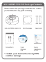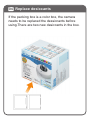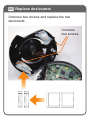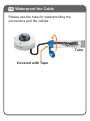
1
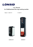
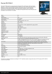
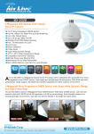
MD-3025/MD-3025-IVS
Mini Dome Network Camera
Quick Installation Guide
Support
You can download the complete guides
and supporting programs from
<http://www.airlivesecurity.com/prod
uct/md-3025/download>, or scan the
QR code here.
Please consult with the FAQs
<http://www.airlivesecurity.com/prod
uct/md-3025/faq> before writing to
OvisLink Tech Support Team for further
assistance
MD-3025
You can download the complete guides
and supporting programs from
<http://www.airlivesecurity.com/prod
uct/md-3025-ivs/download>, or scan
the QR code here.
Please consult with the FAQs
<http://www.airlivesecurity.com/prod
uct/md-3025-ivs/faq> before writing to
OvisLink Tech Support Team for further
assistance
MD-3025-IVS
For any other question, please read the user manual in
the CD or mail to [email protected] for technical
support.
MD-3025/MD-3025-IVS Package Contents
Please check the package contents and contact
your distributor if any part is missing.
MD-3025/MD-3025-IVS
Drill Template
Desiccant
Declaration of Conformity
We, Manufacturer/Importer
OvisLink Corp.
5F, No.6, Lane 130, Min-Chuan Rd., Hsin-Tien Dist.,
New Taipei City 231, Taiwan
Declare that the product
Quick Installation Guide
AirLive Product
is in conformity with
In accordance with 2004/108/EC Directive and 1999/5 EC-R & TTE Directive
Clause
The
al
Tot
AirLive Product
tw
Ne
or
ki
ng
Description
■ XXXXXXXXXXXXXXXX
Information technology equipment - Radio disturbance characteristics Limits and methods of measurement
■ XXXXXXXXXXX
Information technology equipment - Immunity characteristics Limits and methods of measurement
■ XXXXXXXXXXXXXXXXv
Information technology equipment - Safety -- Part 1: General
requirements
Quick Installation Guide
■ CE marking
VER.20XX.XX.XX
So
lut
ion
s
Manufacturer/Importer
Signature:
Name:Albert Yeh
Position/ Title : Vice President
Screw Pack
User
Manual
CD
Place : Taiwan
Date:20XX/XX/XX
Quick
Installation
Guide
* The two spare desiccants are only in the
color box package
I/O Interface
Internal MIC
PoE / RJ-45
DIDO
Audio Out
DC In
01 Before Using the Camera
Please remove the 2 screws. Pull the cable
gently to open the top cover. The Reset button
is LED indicator.
Reset Button
Mirco SD Card Slot
02 Insert MicroSD/MicroSDHC
Remove the SD slot cover and insert MicroSD
card.
64GB
64GB/
Class10
MicroSD
SD slot
cover
Important: Please insert an empty MicroSD
card to prevent from any data lost. Capacity of
32/64GB and Class10 is recommended.
03 Remove the blue tape
Please remove the blue tape.
04 Replace desiccants
If the packing box is a color box, the camera
needs to be replaced the dessiccants before
using.There are two new desiccants in the box.
05 Replace desiccants
Unscrew two screws and replace the two
desiccants.
Unscrew
two screws
06 Replace desiccants
If the packing box is a brown box, it is no need
to put any dessicant in the camera.
07 Surge Protection
Connect SP-100E to the camera for surge
protection.
PoE Port
PoE Switch
SP-100E
DATA + Power
GND
08 Mount the Camera
Use the drill template to mount the camera on
the wall with screws.
Wall
09 Power on the Camera
Connect the 12V1A adaptor or connect the
camera to a PoE switch to power on the camera.
Or
PoE Switch
12V1A adaptor
If you need 2-way audio function, please attach
a speaker to the audio port.
Speaker
10 Waterproof the Cable
Please use the tube for waterproofing the
connectors and the cables.
Tube
Covered with Tape
11 Connect the Camera to the Network
a. Connect the camera to the LAN/PoE port of
the switch/PoE switch.
b. Connect the desktop/ laptop to the LAN port
of the switch/PoE switch.
c. Connect the switch/PoE switch to the LAN
port of the router.
Camera
6
8
PWR LNK/ACT
1
3
5
2
4
7
2
4
6
8
1
3
5
7
Switch
PoE
8-port POE + 2 Combo Gigabit 802.3at
Device Guard Web Smart Switch
PC/NB
G2
LNK/ACT
POE-FSH1008AT
PoE
RST
LNK
LNK
G1
G1
G2
Router
12 Set up the Network Environment
The default IP address of camera is
192.168.1.100. The camera will get IP address
automatically, if it connects to a modem/router
by DHCP function or you can assign a static IP
for the camera.
Camera
192.168.1.100
6
8
PWR LNK/ACT
1
3
5
2
4
7
2
4
6
8
1
3
5
7
Switch
PoE
8-port POE + 2 Combo Gigabit 802.3at
Device Guard Web Smart Switch
PC/NB
192.168.1.101
G2
LNK/ACT
POE-FSH1008AT
PoE
RST
LNK
LNK
G1
G1
DHCP
G2
Router
192.168.1.254
Please make sure the UPnP function is
enabled. For most home use routers, UPnP is
enabled already.
13 Install the Airlive IP Wizard
Please use the CD to install IP Wizard.
The
al
Tot
AirLive Product
tw
Ne
or
ki
ng
XXXXXXXXXX XXXXX XXXX XXXX
VER.201XXXXX
So
lut
ion
s
14 Find Camera on the Network
IP Wizard starts to scan camera automatically.
Click the camera you want to log in.
Important: Please make sure your
desktop/laptop is in the same network segment
with the camera, or your desktop/laptop cannot
connect to the camera in the network.
15 Access Camera on Web UI
Please use IE to log in the camera. The default
username and password is admin/airlive.
You need to install the ActiveX on your PC
when you first access to the camera web UI.
16 Adjust the view angle
When the live view appears,you can adjsut the
view angle of the camera.
Pan
Tilt
Tilt cramp screw
Lens rotation
Cover front
17 Adjust the focus
Please remove the rubber ring and adjust the
focus.
Adjust the Focus
Rubber Ring
18 More Settings on Camera Web UI
You can also adjsut more detail settings in the
camera web UI by IE/Chrome/Firefox. Chrome
and Firefox require QuickTime to display the
live view.
For any other question, please read the user
manual in the CD or mail to the
[email protected] for technical
support.
19 Download the CamPro Mobile
Please visit App Store or Google Play to
download CamPro Mobile. You can use QR
code scanner software directly or simply search
the “AirLive CamPro Mobile".
App Store
Google Play
20 Start the CamPro Mobile
Click the “CamPro Mobile” icon on your device.
Press "Setup"
21 Search and Add the Camera
Press "Add" to start to search camera.
22 Search and Add the Camera
Press "Auto Search".
23 Search and Add the Camera
Slide the list and select the camera of which
you want to view.
24 Search and Add the Camera
Edit the information and Username/Password.
And click “Save”. Default Username/Password
is admin/airlive.
25 Rename the Camera
For easy management, you can rename the
camera. For example, you can name this
camera as "Office".
26 Camea Live View
Press "Back" to four-channel live viewing.
27 Camera Live View
You can select any channel to enlarge the video
or 4-channel view by tapping the screen.
28 Two-Way Audio
Now you can do free voice communication.
Please switch to single channel and enable the
audio function.
Transmit Audio from
Device to Camera
Transmit Audio from
Camera to Device
29 Download and Playback
You can also view the recording files in
MicroSD card and download them into your
device. Please switch to single channel and
press "
" to view the recording list from
You will see the playback list and click the file
which you want to playback.
30 Download and Playback
Click “Play” to playback video, “Save” to save
the video clip to device or “Cancel” to select
another file.
For Android system, you can preview the saved
video file on Android device.
For iOS system, you need to connect to iTunes
for viewing the saved video.
31 Viewing from Internet
Back to step.20, you can see the Device ID
number on the screen. Just click "Query", you
will get the camera public IP and port number to
view the video from Internet. If you cannot see
the video, please setup port forward in the
router.