1
SLICE Mini Distributor
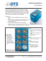
Using the SYS Port
The most common operating mode is to connect the SYS port on the SLICE Mini
Distributor to any one of the four System ports available on a TDAS PLUS Mini
Distributor. Since the SYS port contains all the necessary power, communication and
control signals to operate the SLICE chains, it is the only connection required. (Note:
Each TDAS PLUS Mini Distributor System port supports a maximum of 67.5 W.)
Using the AUX Port
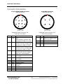
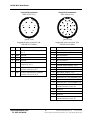
The AUX port contains additional control and status signals for local control. These
signals parallel or complement similar signals on the SYS connector. (See the pin
assignments below for additional details.)
Using the PWR Input
The SLICE Mini Distributor does not contain an internal power source but has
connector inputs for primary (SYS port) and back-up (PWR) input power. If SYS input
power fails, the system will transition to the local power/battery back-up via the PWR
connector. (This input is internally diode-OR’d with the SYS power input.) A typical
input power requirement is 10 W for a stack of 1 SLICE BASE + 6 SLICE BRIDGEs.
See the SLICE User’s Manual for more information on SLICE power requirements.
Using the ON Switch
The pushbutton switch will initialize the system when sufficient power is attached via
the SYS or PWR connector. Press and hold the switch for 2 seconds to start or stop
the system. The PWR/STS light will begin to blink when the system is initializing.
Total time from ON initiation to system ready is typically between 1-2 minutes.
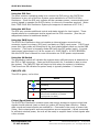
PWR/STS LED
This LED is green, red or blue.
Action
Power input detected; unit OFF
Initializing
Unit ON
Input power is overvoltage –or–
overcurrent condition is present
(cycle power to reset)
Critical Signal Back-up
The SLICE Mini Distributor contains super-cap energy storage to support critical test
signals should external (main or back-up) power fail during data collection. Status,
start record and event signals are enabled for ~5 seconds in the event of power loss.
(Note: Main output power and communications are not supported.) When connected
to sufficient external power, the unit will be ready to support these critical signals after
a few minutes.
[email protected]
+1 562 493 0158
2
13000-30740-MAN (Rev 1)
9 Sept 2015
©Diversified Technical Systems, Inc. - All Rights Reserved