1
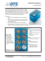
SLICE Mini Distributor
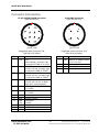
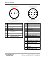
Connector Information
12-pin SLICE CHAIN connector
(EEG.2B.312.CLL)
1
2
3
4-pin PWR connector
(EEG.2B.304.CLL)
8
9
12
10
11
4
1
4
2
3
7
6
5
(panel view)
(panel view)
Suggested cable connector P/N:
FGG.2B.312.CLADxx
Suggested cable connector P/N:
FGG.2B.304.CLADxx
Pin
Use
Function
Pin
Use
Function
1
I/O
/ON
Input voltage; normally high
Connected to GND to turn ON
/START
+5 VDC via 10K; normally high
Connected to GND to START
1
PWR
2
3
4
GND
GND
GND
Back-up or battery input
+9 to +15 VDC
System ground
System ground
System ground
2
I/O
3
I/O
4
INP
5
PWR
6
PWR
7
8
9
GND
GND
USB
5V
10
11
12
I/O
I/O
GND
/EVENT
+5 VDC via 2K; normally high
Connected to GND to EVENT
STATUS
+5 VDC via 10K ref. to GND
High when collecting data
+SLICE_PWR output to chain
(+12 VDC)
+SLICE_PWR output to chain
(+12 VDC)
System ground
System ground
USB power
+5 VDC
USB_DP (data +)
USB_DM (data -)
System ground
[email protected]
+1 562 493 0158
3
13000-30740-MAN (Rev 1)
9 Sept 2015
©Diversified Technical Systems, Inc. - All Rights Reserved