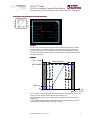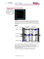
1
PLUS+1TM Guide PLUS+1TM Inverter Function Block Library User Manual 70200003 Inverter FB Library •V102 • April 2011 1 PLUS+1TM Guide PLUS+1 TM Inverter Function Block Library About this manual This manual describes the function blocks of the Inverter Function Block Library SD_PLUS+1_Inverter_FB_Library_10108154v102.SDL The Inverter Function Block Library is a collection of inverter typical function blocks that can be used in any PLUS+1 inverter applications. The Inverter Function Block Library can be added to GUIDE like any other PLUS+1 Library, for more details please refer to PLUS+1 GUIDE manual. The current version of the Inverter Function Block Library is V102, V102 for details on the different released versions please see history at the end of this manual. This manual is included in the Library but it is also available from [email protected] as a separate document under the document number 70200003. Please Note: The library is intended to be compatible with GUIDE version 4.0 and later. Some of the function blocks might only work with Schwarzmüller Inverter PLUS+1 Inverter hardware description files (HWD) because of special EEPROM cell handling. Schwarzmüller Inverter welcomes suggestions for improving our documentation. If you have suggestions for improving this document, please contact Schwarzmüller Inverter at [email protected] © 2010, Schwarzmüller Inverter Schwarzmüller Inverter can accept no responsibility for possible errors in catalogs, brochures and other printed material. Schwarzmüller Inverter reserves the right to alter its products without prior notice. This also applies to products already ordered provides that such alterations can be made without affecting agreed specifications. All trademarks in this material are properties of the respective owners. SauerDanfoss ,the Sauer-Danfoss logotype, the Sauer-Danfoss S-icon, PLUS+1TM, what really matters is inside® and Know-How in MotionTM are trademarks of the Sauer-Danfoss Group. 2 Inverter FB Library V102 • April 2011 PLUS+1 TM Guide PLUS+1 TM Inverter Function Block Library Contents Analog Input Scaling Scaling with two point line 5 Analog Input Scaling with 2pt line .................................................................................................................. 5 Function: ............................................................................................................................................................. 5 Calibration .......................................................................................................................................................... 6 Inputs/Outputs ................................................................................................................................................. 6 Fault and Status Messages ........................................................................................................................... 7 Analog Input Scaling with two point line & Knee 8 Analog Input Scaling with 2pt line and Knee .............................................................................................. 8 Function: ............................................................................................................................................................. 8 Calibration .......................................................................................................................................................... 9 Inputs/Outputs ................................................................................................................................................. 9 Fault and Status Messages ......................................................................................................................... 10 Analog Input Scaling with two point line & AutoAuto-Calibration 11 Analog Input Scaling with 2pt line and Auto-Calibration..................................................................... 11 Function: ........................................................................................................................................................... 11 Calibration ........................................................................................................................................................ 12 Manual Calibration ........................................................................................................................................ 12 Semi-Automatic Calibration ...................................................................................................................... 13 Semi-Automatic Calibration with enable input .................................................................................. 13 Set Defaults ...................................................................................................................................................... 13 Inputs/Outputs ............................................................................................................................................... 14 Fault and Status Messages ......................................................................................................................... 16 Auto--Calibration Analog Input Scaling with two point line & Knee & Auto 17 Analog Input Scaling with 2pt line Knee and Auto-Calibration ......................................................... 17 Function: ........................................................................................................................................................... 17 Calibration ........................................................................................................................................................ 18 Manual Calibration ........................................................................................................................................ 18 Semi-Automatic Calibration ...................................................................................................................... 19 Semi-Automatic Calibration with enable input .................................................................................. 19 Set Defaults ...................................................................................................................................................... 19 Inputs/Outputs ............................................................................................................................................... 20 Fault and Status Messages ......................................................................................................................... 22 Analog Input Scaling with four point line 23 Analog Input Scaling with 4pt line ................................................................................................................ 23 Function: ........................................................................................................................................................... 23 Calibration ........................................................................................................................................................ 24 Inputs/Outputs ............................................................................................................................................... 24 Fault and Status Messages ......................................................................................................................... 26 Analog Input Scaling with four point line & AutoAuto-Calibration 27 Analog Input Scaling with 4pt line and Auto-Calibration..................................................................... 27 Function: ........................................................................................................................................................... 27 Calibration ........................................................................................................................................................ 28 Manual Calibration ........................................................................................................................................ 28 Semi-Automatic Calibration ...................................................................................................................... 29 Semi-Automatic Calibration with enable input .................................................................................. 29 Set Defaults ...................................................................................................................................................... 29 Inputs/Outputs ............................................................................................................................................... 30 Fault and Status Messages ......................................................................................................................... 32 Battery Discharge Indicator 33 Battery Discharge Indicator (BDI) .................................................................................................................. 33 Function: ........................................................................................................................................................... 33 Inputs/Outputs ............................................................................................................................................... 34 Brake and Power 35 Brake and Power .................................................................................................................................................. 35 Function: ........................................................................................................................................................... 35 Inputs/Outputs ............................................................................................................................................... 36 Derating 38 Derating .................................................................................................................................................................. 38 Function: ........................................................................................................................................................... 38 Inputs/Outputs ............................................................................................................................................... 38 Direction Signals 39 Direction Signals .................................................................................................................................................. 39 Function: ........................................................................................................................................................... 39 Inputs/Outputs ............................................................................................................................................... 39 Inverter FB Library •V102 • April 2011 3 PLUS+1TM Guide PLUS+1 TM Inverter Function Block Library Dynamic Drive Curve Generator 40 DDCG........................................................................................................................................................................ 40 Function: ........................................................................................................................................................... 40 Inputs/Outputs ............................................................................................................................................... 40 Error Status Handler 45 Error Status Handler ........................................................................................................................................... 45 Function: ........................................................................................................................................................... 45 Inputs/Outputs ............................................................................................................................................... 45 Error History 48 Error History........................................................................................................................................................... 48 Function: ........................................................................................................................................................... 48 Inputs/Outputs ............................................................................................................................................... 48 Hour Counter 50 Hour Counter ........................................................................................................................................................ 50 Function: ........................................................................................................................................................... 50 Inputs / Outputs ............................................................................................................................................. 50 Main Contactor 51 Main Contactor ..................................................................................................................................................... 51 Function: ........................................................................................................................................................... 51 Inputs/Outputs ............................................................................................................................................... 51 Seat Switch 52 Seat Switch ............................................................................................................................................................. 52 Function: ........................................................................................................................................................... 52 Inputs/Outputs ............................................................................................................................................... 52 Service Counter 53 Service Counter .................................................................................................................................................... 53 Function: ........................................................................................................................................................... 53 Inputs/Outputs ............................................................................................................................................... 53 Solenoid Chopper 55 Solenoid Chopper ............................................................................................................................................... 55 Function: ........................................................................................................................................................... 55 Inputs/Outputs ............................................................................................................................................... 55 Motor Data 57 Motor Data ............................................................................................................................................................. 57 Function: ........................................................................................................................................................... 57 Inputs/Outputs ............................................................................................................................................... 57 Motor Data ROP 58 Motor Data ROP ................................................................................................................................................... 58 Function: ........................................................................................................................................................... 58 Inputs/Outputs ............................................................................................................................................... 58 History Function Block Library 4 Inverter FB Library V102 • April 2011 59 PLUS+1 TM Guide PLUS+1 TM Inverter Function Block Library Analog Input Scaling with two point line Analog Input Scaling with 2pt line Function: The AnIn_2Pt function block can be used for calibrating and scaling an analog input signal with a two point straight line. The analog signal can be given from a joystick, pedal, sensor or from another control device. The function block provides also fault detection, dead band and parameter handling functionality. Diagram: Diagram: Out Out_pct Active input range Value too high FltThd_pct DbndHi_pct DbndLo_pct FltThd_pct Value too low HiOut 100.00 % LoOut_pct 0% CalLo_pct CalHi_pct MaxIn_mV In_pct / In_mV The active input range is defined by the lower and upper calibration point (CalLo_pct, CalHi_pct) as percentages of the maximum input (MaxIn_mV). If required, dead bands can be considered for the calibration points (DbndLo_pct, DbndHi_pct). A fault threshold range (FltThd_pct) provides a safe range for HW tolerances versus error detection if the input value is too high or too low. Inverter FB Library •V102 • April 2011 5 PLUS+1TM Guide PLUS+1 TM Inverter Function Block Library Analog Input Scaling with two point line Notes: A fault needs to be present for a certain time (FltDetTm) before it is declared. The used Fault timer is an up/down counter. This allows faults to be detected if they occur in more than 50% of program cycles. Calibration CalLo and CalHi are stored in an EE memory location with a distinguishable alias for easy updating. Use the PLUS +1TM GUIDE Service and Diagnostic Tool to update CalLo and CalHi. The two calibration points CalLo_pct and CalHi_pct located on Para bus must be connected to S16 memory locations. By default, they are connected to dynamic memory inside the Local_Para page. In case of using the static memory, delete the Local_Para page and use the Para bus to route the signals to the static memory. If multiple AnIn_2Pt function blocks are used in one application, the Namespace feature will have to be used or the memory names have to be changed. In case of using the local parameters included inside the block, calibration can be accomplished as outlined above. Inputs/Outputs Inputs Item/Range Item/Range Description Rst In Flt (BOOL) Reset of input faults: T: Fault is not latched F: Fault is latchet until fixed and power is cycled MaxIn_mV (S32): (0 – 65000[mV]) Maximum rated input in mV Used for ratiometric calculations of calibration points, dead bands and faults In_mV (S32): (0 – 65000[mV]) Analog Input signal in mV Enbl (BOOL) Input to enable function block output Outputs 6 Item/Range Item/Range Description Stat (U16) Status Code in standard bitwise pattern Flt (U16) Fault code in standard bitwise pattern Active (BOOL) HIGH if output is not 0 In_pct (U16): (0 – 10000 [0,01% of MaxIn_mV]) Analog input signal as percentage of MaxIn_mV Out (S32) Output value scaled to HiOut parameter Out _pct (U16): (0 – 10000 [0,01% of HiOut]) Output value as percentage of HiOut parameter Inverter FB Library V102 • April 2011 PLUS+1 TM Guide PLUS+1 TM Inverter Function Block Library Analog Input Scaling with two point line Inputs/Outputs (continued) Parameters Item/Range Item/Range Description CalLo_pct (U16): (0 – 10000[0.01% of MaxIn_mV]; default value: 1000) Low calibration point as percentage of MaxIn_mV. CalHi_pct (U16): (0 – 10000 [0,01% of MaxIn_mV]; default value: 9000) High calibration point as percentage of MaxIn_mV. LoOut_pct (U16): (0-1000 [0,01% of HiOut]; default value: 0) Is the calibrated minimum value of the output as percentage of HiOut. HiOut (U32): (0-20000; default value: 10000) Is the calibrated maximum value of the output, 20000 is the maximum input for the DDCG function block DbndLo_pct (U16): (0 – 1000 [0,01% of MaxIn_mV], default value: 0) Dead band of the low calibration point as percentage of MaxIn_mV. DbndHi_pct (U16): (0 – 1000 [0,01% of MaxIn_mV], default value: 0) Dead band of the high calibration point as percentage of MaxIn_mV. FltThd_pct (U16): (0 to 5000 [0,01% of MaxIn_mV]; default value: 500) Fault threshold of the lower and upper calibration points as percentage of MaxIn_mV. FltDetTm_ms (U16): (0 – 10000 [ms]; default value: 1000) Fault detection time in ms. The time that a fault needs to be present before it is declared Fault and Status Messages Fault: The “Fault” output is the fault code of the function block. Bit Position Value Range/Type -- 0x0000 Input value is OK 1 0x8001 Input value is too low 2 0x8002 Input value is too high 5 0x8010 Value out of range (MaxIn_mV < In_mV) 16 0xX000 Custom/Standard code bit Status: The “Stat” output is the status code of the function block. Bit Position Value Range/Type -- 0x0000 Block is OK 1 0x8001 Block is not calibrated (CalLo_pct = 0 and CalHi_pct = 0) 2 0x8002 Block is currently in a calibration cycle (CalLo_pct ≠ 0 and CalHi_pct = 0) 3 0x8004 Parameters are corrupt 4 0x8008 Invalid Setup/ Calibration 16 0xX000 Custom/Standard code bit Inverter FB Library •V102 • April 2011 7 PLUS+1TM Guide PLUS+1 TM Inverter Function Block Library Analog Input Scaling with two point line & Knee Analog Input Scaling with 2pt line and Knee Function: The AnIn_2Pt function block can be used for calibrating and scaling an analog input signal with a two point line. The line can be adjusted to a knee profile. The analog signal can be given from a joystick, pedal, sensor or from another control device. The function block provides also fault detection, dead band and parameter handling functionality. Diagram: Diagram: Out Out_pct Active input range Value too high FltThd_pct DbndHi_pct DbndLo_pct FltThd_pct Value too low HiOut 100.00 % MidOut_pct LoOut_pct 0% CalLo_pct CalMid_pct CalHi_pct MaxIn_mV In_pct / In_mV The active input range is defined by the lower and upper calibration point (CalLo_pct, CalHi_pct) as percentages of the maximum input (MaxIn_mV). The knee profile is defined by the parameter CalMid_pct and MidOut_pct. If required, dead bands can be considered for the calibration points (DbndLo_pct, DbndHi_pct). A fault threshold range (FltThd_pct) provides a safe range for HW tolerances versus error detection if the input value is too high or too low. 8 Inverter FB Library V102 • April 2011 PLUS+1 TM Guide PLUS+1 TM Inverter Function Block Library Analog Input Scaling with two point line & Knee Notes: A fault needs to be present for a certain time (FltDetTm) before it is declared. The used Fault timer is an up/down counter. This allows faults to be detected if they occur in more than 50% of program cycles. Calibration CalLo , CalMid and CalHi are stored in an EE memory location with a distinguishable alias for easy updating. Use the PLUS +1TM GUIDE Service and Diagnostic Tool to update CalLo, CalMid and CalHi. The three calibration points CalLo_pct, CalMid and CalHi_pct located on Para bus must be connected to S16 memory locations. By default, they are connected to dynamic memory inside the Local_Para page. In case of using the static memory, delete the Local_Para page and use the Para bus to route the signals to the static memory. If multiple AnIn_2PtKnee function blocks are used in one application, the Namespace feature will have to be used or the memory names have to be changed. In case of using the local parameters included inside the block, calibration can be accomplished by one of the three methods outlined below. Inputs/Outputs Inputs Item/Range Item/Range Description Rst In Flt (BOOL) Reset of input faults: T: Fault is not latched F: Fault is latchet until fixed and power is cycled MaxIn_mV (S32): (0 – 6500[mV]) Maximum rated input in mV Used for ratiometric calculations of calibration points, dead bands and faults In_mV (S32): (0 – 65000[mV]) Analog Input signal in mV Enbl (BOOL) Input to enable function block output Outputs Item/Range Item/Range Description Stat (U16) Status Code in standard bitwise pattern Flt (U16) Fault code in standard bitwise pattern Active (BOOL) HIGH if output is not 0 In_pct (U16): (0 – 10000 [0,01% of MaxIn_mV]) Analog input signal as percentage of MaxIn_mV Out (S32) Output value scaled to HiOut parameter Out _pct (U16): (0 – 10000 [0,01% of HiOut]) Output value as percentage of HiOut parameter Inverter FB Library •V102 • April 2011 9 PLUS+1TM Guide PLUS+1 TM Inverter Function Block Library Analog Input Scaling with two point line & Knee Inputs/Outputs (continued) Parameters Item/Range Item/Range Description CalLo_pct (U16): (0 – 10000[0.01% of MaxIn_mV]; default value: 1000) Low calibration point as percentage of MaxIn_mV. CalMid_pct (U16): (0 – 10000 [0,01% of active input range; default value: 5000) Middle calibration point as percentage of active input range from CalLo_pct to CalHi_pct CalHi_pct (U16): (0 – 10000 [0,01% of MaxIn_mV]; default value: 9000) High calibration point as percentage of MaxIn_mV. LoOut_pct (U16): (0-1000 [0,01% of HiOut]; default value: 0) Is the calibrated minimum value of the output as percentage of HiOut. MidOut_pct (U16): (0-1000 [0,01% of HiOut]; default value: 0) Is the calibrated middle value of the output as percentage of HiOut. HiOut (U32): (0-20000; default value: 10000) Is the calibrated maximum value of the output, 20000 is the maximum input for the DDCG function block DbndLo_pct (U16): (0 – 1000 [0,01% of MaxIn_mV], default value: 0) Dead band of the low calibration point as percentage of MaxIn_mV. DbndHi_pct (U16): (0 – 1000 [0,01% of MaxIn_mV], default value: 0) Dead band of the high calibration point as percentage of MaxIn_mV. FltThd_pct (U16): (0 to 5000 [0,01% of MaxIn_mV]; default value: 500) Fault threshold of the lower and upper calibration points as percentage of MaxIn_mV. FltDetTm_ms (U16): (0 – 10000 [ms]; default value: 1000) Fault detection time in ms. The time that a fault needs to be present before it is declared Fault and Status Messages Fault: The “Fault” output is the fault code of the function block. Bit Position Value Range/Type -- 0x0000 Input value is OK 1 0x8001 Input value is too low 2 0x8002 Input value is too high 5 0x8010 Value out of range (MaxIn_mV < In_mV) 16 0xX000 Custom/Standard code bit Status: The “Stat” output is the status code of the function block. 10 Bit Position Value Range/Type -- 0x0000 Block is OK 1 0x8001 Block is not calibrated (CalLo_pct = 0 and CalHi_pct = 0) 2 0x8002 Block is currently in a calibration cycle (CalLo_pct ≠ 0 and CalHi_pct = 0) 3 0x8004 Parameters are corrupt 4 0x8008 Invalid Setup/ Calibration 16 0xX000 Custom/Standard code bit Inverter FB Library V102 • April 2011 PLUS+1 TM Guide PLUS+1 TM Inverter Function Block Library Analog Input Scaling with two point line & Auto-Calibration Analog Input Scaling with 2pt line and Autouto-Calibration Function: Function: The AnIn_2Pt_AC function block can be used for calibrating and scaling an analog input signal with a two point straight line. The analog signal can be given from a joystick, pedal, sensor or from another control device. The function block provides also semi-automatic calibration functions, fault detection, dead band and parameter handling functionality. Diagram: Diagram: Out Out_pct Active input range Value too high FltThd_pct DbndHi_pct DbndLo_pct FltThd_pct Value too low HiOut 100.00 % LoOut_pct 0% CalLo_pct CalHi_pct MaxIn_mV In_pct / In_mV The active input range is defined by the lower and upper calibration point (CalLo_pct, CalHi_pct) as percentages of the maximum input (MaxIn_mV). If required, dead bands can be considered for the calibration points (DbndLo_pct, DbndHi_pct). A fault threshold range (FltThd_pct) provides a safe range for HW tolerances versus error detection if the input value is too high or too low. Inverter FB Library •V102 • April 2011 11 PLUS+1TM Guide PLUS+1 TM Inverter Function Block Library Analog Input Scaling with two point line & Auto-Calibration Notes: A fault needs to be present for a certain time (FltDetTm) before it is declared. The used Fault timer is an up/down counter. This allows faults to be detected if they occur in more than 50% of program cycles. StorCalLo, StorCalHi and SetDef are outputs intended to control the EE_PROM blocks in the parameters pages. Calibration CalWin_pct 0% CalLo_pct ExpCalLo_pct CalWin_pct CalHi_pct In_pct ExpCalHi_pct It is highly recommended to start the calibration with the lower calibration point, means HW source of the analog signal is in neutral position when activating the calibration. Otherwise the calibration status message can be wrong, since the block can’t distinguish if value “0” for the Lower calibration point is the correct and allowed value or if it’s just not calibrated yet. The two calibration points CalLo_pct and CalHi_pct located on Para bus must be connected to S16 memory locations. By default, they are connected to dynamic memory inside the Local_Para page. In case of using the static memory, delete the Local_Para page and use the Para bus to route the signals to the static memory. If multiple Sensor_2Pt_AC function blocks are used in one application, the Namespace feature will have to be used or the memory names have to be changed. In case of using the local parameters included inside the block, calibration can be accomplished by one of the three methods outlined below. Manual Calibration CalLo and CalHi are stored in an EE memory location with a distinguishable alias for easy updating. Use the PLUS +1TM GUIDE Service and Diagnostic Tool to update CalLo and CalHi. 12 Inverter FB Library V102 • April 2011 PLUS+1 TM Guide PLUS+1 TM Inverter Function Block Library Analog Input Scaling with two point line & Auto-Calibration Calibration (continued) SemiSemi-Automatic Calibration The two calibration points are stored in the same EE memory locations as in Manual Calibration. The Calibration Command must be set to 1 (Enable Semi-automatic Calibration). As long as the stored values for CalLo and CalHi are zero, the function is not calibrated and the input is ready for Semi-Automatic Calibration. The Expected Calibration Points (ExpCalLo_pct, ExpCalHi_pct) specify the center of the Calibration Windows. If the input value is within the calibration window for the low or high calibration point for duration CalDetTm_ms, the last value is captured and stored for that calibration point. After storing values for both calibration points, semi-automatic calibration is complete. Calibration mode can be activated by either setting the Calibration Command input to 4 or if the stored values of parameters CalLo_pct and CalHi_pct are zero and the Calibration Command equals 1. CalLo_pct and CalHi_pct can be set to zero by service tool. SemiSemi-Automatic Calibration with enable input The two calibration points are stored in the same EE memory locations as in Manual Calibration. The Calibration Command must be set to 2 (Enable Semi-automatic Calibration with enable input). As long as the stored values for CalLo and CalHi are zero, the function is not calibrated and the input is ready for Semi-Automatic Calibration with Enable Input. The Expected Calibration Points specify the center of the Calibration Windows. If the input value is within the expected window for Low Calibration Point and the Enable Input has a rising edge (0 -> 1) the value is captured and stored. If the input value is within the expected window for High Calibration Point for duration CalDetTm_ms, the last value is captured and stored. After storing values for both calibration points, semi-automatic calibration is complete. Calibration Mode can be activated by either setting the Calibration Command Input to 4 or if the stored values of parameters CalLo_pct and CalHi_pct are zero and if the Calibration Command equals 1. CalLo_pct and CalHi_pct can be set to zero by service tool. Set Defaults If the Calibration Command equals 3, the Set Defaults variable SetDef in the parameter bus becomes TRUE. In this case the default values for CalLo and CalHi will be stored into memory. The default values are constants on input DEFAULT of these memory blocks. Inverter FB Library •V102 • April 2011 13 PLUS+1TM Guide PLUS+1 TM Inverter Function Block Library Analog Input Scaling with two point line & Auto-Calibration Inputs/Outputs Inputs Item/Range Item/Range Description Cal Cmd (U8): (0 - 4) Calibration Command 0: Manual calibration 1: Semi Auto Cal 2: Semi Auto Cal with enable input 3: Set Calibration values to defaults 4: Clear Calibration Rst In Flt (BOOL) Reset of input faults: T: Fault is not latched F: Fault is latchet until fixed and power is cycled MaxIn_mV (S32): (0 – 65000[mV]) Maximum rated input in mV Used for ratiometric calculations of calibration points, dead bands and faults In_mV (S32): (0 – 65000[mV]) Analog Input signal in mV Enbl (BOOL) Input to enable function block output Outputs 14 Item/Range Item/Range Description Stat (U16) Status Code in standard bitwise pattern Flt (U16) Fault code in standard bitwise pattern Active (BOOL) HIGH if output is not 0 In_pct (U16): (0 – 10000 [0,01% of MaxIn_mV]) Analog input signal as percentage of MaxIn_mV Out (S32) Output value scaled to HiOut parameter Out _pct (U16): (0 – 10000 [0,01% of HiOut]) Output value as percentage of HiOut parameter Inverter FB Library V102 • April 2011 PLUS+1 TM Guide PLUS+1 TM Inverter Function Block Library Analog Input Scaling with two point line & Auto-Calibration Inputs/Outputs (continued) Parameters Item/Range Item/Range Description StorCalLo (BOOL) Signal used to store low calibration value StorCalHi (BOOL) Signal used to store high calibration value SetDef (BOOL) Signal used to set default calibration values CalLo_pct (U16): (0 – 10000[0.01% of MaxIn_mV]; default value: 1000) Low calibration point as percentage of MaxIn_mV. CalHi_pct (U16): (0 – 10000 [0,01% of MaxIn_mV]; default value: 9000) High calibration point as percentage of MaxIn_mV. LoOut_pct (U16): (0-1000 [0,01% of HiOut]; default value: 0) Is the calibrated minimum value of the output as percentage of HiOut. HiOut (U32): (0-20000; default value: 10000) Is the calibrated maximum value of the output, 20000 is the maximum input for the DDCG function block DbndLo_pct (U16): (0 – 1000 [0,01% of MaxIn_mV], default value: 0) Dead band of the low calibration point as percentage of MaxIn_mV. DbndHi_pct (U16): (0 – 1000 [0,01% of MaxIn_mV], default value: 0) Dead band of the high calibration point as percentage of MaxIn_mV. FltThd_pct (U16): (0 to 5000 [0,01% of MaxIn_mV]; default value: 500) Fault threshold of the lower and upper calibration points as percentage of MaxIn_mV. FltDetTm_ms (U16): (0 – 10000 [ms]; default value: 1000) Fault detection time in ms. The time that a fault needs to be present before it is declared ExpCalLo_pct (U16): (0 – 10000 [0,01% of MaxIn_mV], default value: 1000) Expected value of the lower calibration point, as percentage of MaxIn_mV, used to determine center of an acceptable calibration window. ExpCalHi_pct (U16): (0 – 10000 [0,01% of MaxIn_mV], default value: 9000) Expected value of the upper calibration point as percentage of MaxIn_mV, used to determine center of an acceptable calibration window. CalWin_pct (U16): (0 – 5000 [0,01% of MaxIn_mV]; default value: 500) Amount +/- expected calibration points used to determine acceptable calibration window. Specified by units of .01% of Snsr Pwr CalDetTm_ms (U16): (0 – 10000 [ms]; default value: 1000) Calibration capture time in ms Inverter FB Library •V102 • April 2011 15 PLUS+1TM Guide PLUS+1 TM Inverter Function Block Library Analog Input Scaling with two point line & Auto-Calibration Fault and Status Messages Fault: The “Fault” output is the fault code of the function block. Bit Position Value Range/Type -- 0x0000 Input value is OK 1 0x8001 Input value is too low 2 0x8002 Input value is too high 5 0x8010 Value out of range (MaxIn_mV < In_mV) or (CalCmd > 4) 16 0xX000 Custom/Standard code bit Status: The “Stat” output is the status code of the function block. 16 Bit Position Value Range/Type -- 0x0000 Block is OK 1 0x8001 Block is not calibrated (CalLo_pct = 0 and CalHi_pct = 0) 2 0x8002 Block is currently in a calibration cycle (CalLo_pct ≠ 0 and CalHi_pct = 0) 3 0x8004 Parameters are corrupt 4 0x8008 Invalid Setup/ Calibration 16 0xX000 Custom/Standard code bit Inverter FB Library V102 • April 2011 PLUS+1 TM Guide PLUS+1 TM Inverter Function Block Library Analog Input Scaling with two point line & Knee & AutoCalibration Analog Input Scaling with 2pt line Knee and AutoAuto-Calibration Calibration Function: The AnIn_2Pt_AC function block can be used for calibrating and scaling an analog input signal with a two point line. The line can be adjusted to a knee profile. The analog signal can be given from a joystick, pedal, sensor or from another control device. The function block provides also semi-automatic calibration functions, fault detection, dead band and parameter handling functionality. Diagram: Diagram: Out Out_pct Active input range Value too high FltThd_pct DbndHi_pct DbndLo_pct FltThd_pct Value too low HiOut 100.00 % MidOut_pct LoOut_pct 0% CalLo_pct CalMid_pct CalHi_pct MaxIn_mV In_pct / In_mV The active input range is defined by the lower and upper calibration point (CalLo_pct, CalHi_pct) as percentages of the maximum input (MaxIn_mV). The knee profile is defined by the parameter CalMid_pct and MidOut_pct. If required, dead bands can be considered for the calibration points (DbndLo_pct, DbndHi_pct). A fault threshold range (FltThd_pct) provides a safe range for HW tolerances versus error detection if the input value is too high or too low. Inverter FB Library •V102 • April 2011 17 PLUS+1TM Guide PLUS+1 TM Inverter Function Block Library Analog Input Scaling with two point line & Knee & AutoCalibration Notes: A fault needs to be present for a certain time (FltDetTm) before it is declared. The used Fault timer is an up/down counter. This allows faults to be detected if they occur in more than 50% of program cycles. StorCalLo, StorCalHi and SetDef are outputs intended to control the EE_PROM blocks in the parameters pages. Calibration CalWin_pct 0% CalLo_pct ExpCalLo_pct CalWin_pct CalHi_pct In_pct ExpCalHi_pct It is highly recommended to start the calibration with the lower calibration point, means HW source of the analog signal is in neutral position when activating the calibration. Otherwise the calibration status message can be wrong, since the block can’t distinguish if value “0” for the Lower calibration point is the correct and allowed value or if it’s just not calibrated yet. The three calibration points CalLo_pct, CalMid_pct and CalHi_pct located on Para bus must be connected to S16 memory locations. By default, they are connected to dynamic memory inside the Local_Para page. In case of using the static memory, delete the Local_Para page and use the Para bus to route the signals to the static memory. If multiple Sensor_2PtKnee_AC function blocks are used in one application, the Namespace feature will have to be used or the memory names have to be changed. In case of using the local parameters included inside the block, calibration can be accomplished by one of the three methods outlined below. Manual Calibration CalLo , CalMid_pct and CalHi are stored in an EE memory location with a distinguishable alias for easy updating. Use the PLUS +1TM GUIDE Service and Diagnostic Tool to update CalLo, CalMid_pct and CalHi. 18 Inverter FB Library V102 • April 2011 PLUS+1 TM Guide PLUS+1 TM Inverter Function Block Library Analog Input Scaling with two point line & Knee & AutoCalibration Calibration (continued) SemiSemi-Automatic Calibration The three calibration points are stored in the same EE memory locations as in Manual Calibration. The Calibration Command must be set to 1 (Enable Semi-automatic Calibration). As long as the stored values for CalLo and CalHi are zero, the function is not calibrated and the input is ready for Semi-Automatic Calibration. The Expected Calibration Points (ExpCalLo_pct, ExpCalHi_pct) specify the center of the Calibration Windows. If the input value is within the calibration window for the low or high calibration point for duration CalDetTm_ms, the last value is captured and stored for that calibration point. After storing values for both calibration points, semi-automatic calibration is complete. Calibration mode can be activated by either setting the Calibration Command input to 4 or if the stored values of parameters CalLo_pct and CalHi_pct are zero and the Calibration Command equals 1. CalLo_pct and CalHi_pct can be set to zero by service tool. CalMid_pct can only be set manually. SemiSemi-Automatic Calibration with enable input The two calibration points are stored in the same EE memory locations as in Manual Calibration. The Calibration Command must be set to 2 (Enable Semi-automatic Calibration with enable input). As long as the stored values for CalLo and CalHi are zero, the function is not calibrated and the input is ready for Semi-Automatic Calibration with Enable Input. The Expected Calibration Points specify the center of the Calibration Windows. If the input value is within the expected window for Low Calibration Point and the Enable Input has a rising edge (0 -> 1) the value is captured and stored. If the input value is within the expected window for High Calibration Point for duration CalDetTm_ms, the last value is captured and stored. After storing values for both calibration points, semi-automatic calibration is complete. Calibration Mode can be activated by either setting the Calibration Command Input to 4 or if the stored values of parameters CalLo_pct and CalHi_pct are zero and if the Calibration Command equals 1. CalLo_pct and CalHi_pct can be set to zero by service tool. CalMid_pct can only be set manually. Set Defaults If the Calibration Command equals 3, the Set Defaults variable SetDef in the parameter bus becomes TRUE. In this case the default values for CalLo and CalHi will be stored into memory. The default values are constants on input DEFAULT of these memory blocks. Inverter FB Library •V102 • April 2011 19 PLUS+1TM Guide PLUS+1 TM Inverter Function Block Library Analog Input Scaling with two point line & Knee & AutoCalibration Inputs/Outputs Inputs Item/Range Item/Range Description Cal Cmd (U8): (0 - 4) Calibration Command 0: Manual calibration 1: Semi Auto Cal 2: Semi Auto Cal with enable input 3: Set Calibration values to defaults 4: Clear Calibration Rst In Flt (BOOL) Reset of input faults: T: Fault is not latched F: Fault is latchet until fixed and power is cycled MaxIn_mV (S32): (0 – 65000[mV]) Maximum rated input in mV Used for ratiometric calculations of calibration points, dead bands and faults In_mV (S32): (0 – 65000[mV]) Analog Input signal in mV Enbl (BOOL) Input to enable function block output Outputs 20 Item/Range Item/Range Description Stat (U16) Status Code in standard bitwise pattern Flt (U16) Fault code in standard bitwise pattern Active (BOOL) HIGH if output is not 0 In_pct (U16): (0 – 10000 [0,01% of MaxIn_mV]) Analog input signal as percentage of MaxIn_mV Out (S32) Output value scaled to HiOut parameter Out _pct (U16): (0 – 10000 [0,01% of HiOut]) Output value as percentage of HiOut parameter Inverter FB Library V102 • April 2011 PLUS+1 TM Guide PLUS+1 TM Inverter Function Block Library Analog Input Scaling with two point line & Knee & AutoCalibration Inputs/Outputs (continued) Parameters Item/Range Item/Range Description StorCalLo (BOOL) Signal used to store low calibration value StorCalHi (BOOL) Signal used to store high calibration value SetDef (BOOL) Signal used to set default calibration values CalLo_pct (U16): (0 – 10000[0.01% of MaxIn_mV]; defaultvalue: 1000) Low calibration point as percentage of MaxIn_mV. CalMid_pct (U16): (0 – 10000 [0,01% of active input range]; default value: 5000) Middle calibration point as percentage of active input range from CalLo_pct to CalHi_pct. CalHi_pct (U16): (0 – 10000 [0,01% of MaxIn_mV]; default value: 9000) High calibration point as percentage of MaxIn_mV. LoOut_pct (U16): (0-1000 [0,01% of HiOut]; default value: 0) Is the calibrated minimum value of the output as percentage of HiOut. MidOut_pct (U16): (0-1000 [0,01% of HiOut]; default value: 5000) Is the calibrated middle value of the output as percentage of HiOut. HiOut (U32): (0-20000; default value: 10000) Is the calibrated maximum value of the output, 20000 is the maximum input for the DDCG function block DbndLo_pct (U16): (0 – 1000 [0,01% of MaxIn_mV], default value: 0) Dead band of the low calibration point as percentage of MaxIn_mV. DbndHi_pct (U16): (0 – 1000 [0,01% of MaxIn_mV], default value: 0) Dead band of the high calibration point as percentage of MaxIn_mV. FltThd_pct (U16): (0 to 5000 [0,01% of MaxIn_mV]; default value: 500) Fault threshold of the lower and upper calibration points as percentage of MaxIn_mV. FltDetTm_ms (U16): (0 – 10000 [ms]; default value: 1000) Fault detection time in ms. The time that a fault needs to be present before it is declared ExpCalLo_pct (U16): (0 – 10000 [0,01% of MaxIn_mV], default value: 1000) Expected value of the lower calibration point, as percentage of MaxIn_mV, used to determine center of an acceptable calibration window. ExpCalHi_pct (U16): (0 – 10000 [0,01% of MaxIn_mV], default value: 9000) Expected value of the upper calibration point as percentage of MaxIn_mV, used to determine center of an acceptable calibration window. CalWin_pct (U16): (0 – 5000 [0,01% of MaxIn_mV]; default value: 500) Amount +/- expected calibration points used to determine acceptable calibration window. Specified by units of .01% of Snsr Pwr CalDetTm_ms (U16) (0 – 10000 [ms]; default value: 1000) Calibration capture time in ms Inverter FB Library •V102 • April 2011 21 PLUS+1TM Guide PLUS+1 TM Inverter Function Block Library Analog Input Scaling with two point line & Knee & AutoCalibration Fault and Status Messages Fault: The “Fault” output is the fault code of the function block. Bit Position Value Range/Type -- 0x0000 Input value is OK 1 0x8001 Input value is too low 2 0x8002 Input value is too high 5 0x8010 Value out of range (MaxIn_mV < In_mV) or (CalCmd > 4) 16 0xX000 Custom/Standard code bit Status: The “Stat” output is the status code of the function block. 22 Bit Position Value Range/Type -- 0x0000 Block is OK 1 0x8001 Block is not calibrated (CalLo_pct = 0 and CalHi_pct = 0) 2 0x8002 Block is currently in a calibration cycle (CalLo_pct ≠ 0 and CalHi_pct = 0) 3 0x8004 Parameters are corrupt 4 0x8008 Invalid Setup/ Calibration 16 0xX000 Custom/Standard code bit Inverter FB Library V102 • April 2011 PLUS+1 TM Guide PLUS+1 TM Inverter Function Block Library Analog Input Scaling with four point line Analog Input Scaling with 4pt line Function: The AnIn_4Pt function block can be used for calibrating and scaling an analog input signal with a four point line. The analog signal can be given from a joystick, pedal, sensor or from another control device. The function block provides also fault detection, dead band and parameter handling functionality. Diagram: Diagram: Out Active negative input range Out_pct Active positive input range CalHiNeg_pct CalLoNeg_pct DbndHiPos_pct FltThd_pct Value too high DbndLoPos_pct HiOutNeg -100.00% DbndLoNeg_pct 0% LoOutNeg_pct FltThd_pct DbndHiNeg_pct LoOutPos_pct Value too low HiOutPos 100.00% In_pct / In_mV CalHiPos_pct CalLoPos_pct MaxIn_mV The active positive input range is defined by the positive lower and upper calibration point (CalLoPos_pct, CalHiPos_pct) as percentages of the maximum input (MaxIn_mV). The active negative input range is defined by the negative lower and upper calibration point (CalLoNeg_pct, CalHiNeg_pct) as percentages of the maximum input (MaxIn_mV). If required, dead bands can be considered for all four calibration points (DbndLoPos_pct, DbndHiPos_pct, DbndLoNeg_pct, DbndHiNeg_pct). Inverter FB Library •V102 • April 2011 23 PLUS+1TM Guide PLUS+1 TM Inverter Function Block Library Analog Input Scaling with four point line A fault threshold range (FltThd_pct) provides a safe range for HW tolerances versus error detection if the input value is too high or too low. Notes: A fault needs to be present for a certain time (FltDetTm) before it is declared. The used Fault timer is an up/down counter. This allows faults to be detected if they occur in more than 50% of program cycles. Calibration CalLoPos_pct, CalHiPos_pct, CalLoNeg_pct and CalHiNeg_pct are stored in an EE memory location with a distinguishable alias for easy updating. Use the PLUS +1TM GUIDE Service and Diagnostic Tool to update these parameter. The four calibration points CalLoPos_pct, CalHiPos_pct, CalLoNeg_pct and CalHiNeg_pct located on Para bus must be connected to S16 memory locations. By default, they are connected to dynamic memory inside the Local_Para page. In case of using the static memory, delete the Local_Para page and use the Para bus to route the signals to the static memory. If multiple AnIn_4Pt function blocks are used in one application, the Namespace feature will have to be used or the memory names have to be changed. In case of using the local parameters included inside the block, calibration can be accomplished as outlined above. Inputs/Outputs Inputs Item/Range Item/Range Description Rst In Flt (BOOL) Reset of input faults: T: Fault is not latched F: Fault is latchet until fixed and power is cycled MaxIn_mV (S32): (0 – 65000[mV]) Maximum rated input in mV Used for ratiometric calculations of calibration points, dead bands and faults In_mV (S32): (0 – 65000[mV]) Analog Input signal in mV EnblPos (BOOL) Input to enable the positive part of the function block output EnblNeg (BOOL) Input to enable the negative part of the function block output Outputs 24 Item/Range Item/Range Description Stat (U16) Status Code in standard bitwise pattern Flt (U16) Fault code in standard bitwise pattern ActivePos (BOOL) HIGH if output is greater than 0 ActiveNeg (BOOL) HIGH if output is less than 0 In_pct (U16): (0 – 10000 [0,01% of MaxIn_mV]) Analog input signal as percentage of MaxIn_mV Inverter FB Library V102 • April 2011 PLUS+1 TM Guide PLUS+1 TM Inverter Function Block Library Analog Input Scaling with four point line Inputs/Outputs (continued) Outputs Item/Rang Item/Range /Range Description Out (S32) Output value scaled to HiOutPos or HighOutNeg parameter Out _pct (U16) (0 – 10000 [0,01% of HiOut]) Output value as percentage of HiOut parameter Parameters Item/Range Item/Range Description CalLoPos_pct (U16): (0 – 10000[0.01% of MaxIn_mV]; default value: 5500) Low calibration point for the positive part as percentage of MaxIn_mV. CalHiPos_pct (U16): (0 – 10000 [0,01% of MaxIn_mV]; default value: 9000) High calibration point for the positive part as percentage of MaxIn_mV. LoOutPos_pct (U16): (0-1000 [0,01% of HiOut]; default value: 0) Is the calibrated minimum value of the output for the positive part as percentage of HiOut. HiOutPos (U32): (0-20000; default value: 10000) Is the calibrated maximum value of the output for the positive part, 20000 is the maximum input for the DDCG function block DbndLoPos_pct (U16): (0 – 1000 [0,01% of MaxIn_mV], default value: 0) Dead band of the low calibration point for the positive part as percentage of MaxIn_mV. DbndHiPos_pct (U16): (0 – 1000 [0,01% of MaxIn_mV], default value: 0) Dead band of the high calibration point for the positive part as percentage of MaxIn_mV. CalLoNeg_pct (U16): (0 – 10000[0.01% of MaxIn_mV]; default value: 4500) Low calibration point for the negative part as percentage of MaxIn_mV. CalHiNeg_pct (U16): (0 – 10000 [0,01% of MaxIn_mV]; default value: 9000) High calibration point for the negative part as percentage of MaxIn_mV. LoOutNeg_pct (U16): (0-1000 [0,01% of HiOut]; default value: 0) Is the calibrated minimum value of the output for the negative part as percentage of HiOut. HiOutNeg (U32): (0-20000; default value: 10000) Is the calibrated maximum value of the output for the negative part, 20000 is the maximum input for the DDCG function block DbndLoNeg_pct (U16): (0 – 1000 [0,01% of MaxIn_mV], default value: 0) Dead band of the low calibration point for the negative part as percentage of MaxIn_mV. DbndHiNeg_pct (U16): (0 – 1000 [0,01% of MaxIn_mV], default value: 0) Dead band of the high calibration point for the negative part as percentage of MaxIn_mV. FltThd_pct (U16): (0 to 5000 [0,01% of MaxIn_mV]; default value: 500) Fault threshold of the lower and upper calibration points as percentage of MaxIn_mV. FltDetTm_ms (U16): (0 – 10000 [ms]; default value: 1000) Fault detection time in ms. The time that a fault needs to be present before it is declared Inverter FB Library •V102 • April 2011 25 PLUS+1TM Guide PLUS+1 TM Inverter Function Block Library Analog Input Scaling with four point line Fault and Status Messages Fault: The “Fault” output is the fault code of the function block. Bit Position Value Range/Type -- 0x0000 Input value is OK 1 0x8001 Input value is too low 2 0x8002 Input value is too high 5 0x8010 Value out of range (MaxIn_mV < In_mV) 16 0xX000 Custom/Standard code bit Status: The “Stat” output is the status code of the function block. 26 Bit Position Value Range/Type -- 0x0000 Block is OK 1 0x8001 Block is not calibrated (CalLo_pct = 0 and CalHi_pct = 0) 2 0x8002 Block is currently in a calibration cycle (CalLo_pct ≠ 0 and CalHi_pct = 0) 3 0x8004 Parameters are corrupt 4 0x8008 Invalid Setup/ Calibration 16 0xX000 Custom/Standard code bit Inverter FB Library V102 • April 2011 PLUS+1 TM Guide PLUS+1 TM Inverter Function Block Library Analog Input Scaling with four point line & Auto-Calibration Analog Input Scaling with 4pt line and AutoAuto-Calibration Function: Function: The AnIn_4Pt_AC function block can be used for calibrating and scaling an analog input signal with a four point line. The analog signal can be given from a joystick, pedal, sensor or from another control device. The function block provides also semiautomatic calibration functions, fault detection, dead band and parameter handling functionality. Diagram: Diagram: Out Active negative input range Out_pct Active positive input range CalHiNeg_pct CalLoNeg_pct DbndHiPos_pct FltThd_pct Value too high HiOutNeg -100.00% DbndLoPos_pct LoOutNeg_pct DbndLoNeg_pct 0% FltThd_pct DbndHiNeg_pct LoOutPos_pct Value too low HiOutPos 100.00% In_pct / In_mV CalHiPos_pct CalLoPos_pct MaxIn_mV The active positive input range is defined by the positive lower and upper calibration point (CalLoPos_pct, CalHiPos_pct) as percentages of the maximum input (MaxIn_mV). The active negative input range is defined by the negative lower and upper calibration point (CalLoNeg_pct, CalHiNeg_pct) as percentages of the maximum input (MaxIn_mV). If required, dead bands can be considered for all four calibration points (DbndLoPos_pct, DbndHiPos_pct, DbndLoNeg_pct, DbndHiNeg_pct). Inverter FB Library •V102 • April 2011 27 PLUS+1TM Guide PLUS+1 TM Inverter Function Block Library Analog Input Scaling with four point line & Auto-Calibration A fault threshold range (FltThd_pct) provides a safe range for HW tolerances versus error detection if the input value is too high or too low. Notes: A fault needs to be present for a certain time (FltDetTm) before it is declared. The used Fault timer is an up/down counter. This allows faults to be detected if they occur in more than 50% of program cycles. StorCalLoPos, StorCalHiPos, StorCalLoNeg, StorCalHiNeg and SetDef are outputs intended to control the EE_PROM blocks in the parameters pages. Calibration CalWin_pct CalWin_pct In_pct 0% CalLoxxx_pct ExpCalLoxxx_pct CalHixxx_pct ExpCalHixxx_pct xxx = Pos or Neg It is highly recommended to start the calibration with the lower calibration point, means HW source of the analog signal is in neutral position when activating the calibration. Otherwise the calibration status message can be wrong, since the block can’t distinguish if value “0” for the Lower calibration point is the correct and allowed value or if it’s just not calibrated yet. The four calibration points CalLoPos_pct, CalHiPos_pct, CalLoNeg_pct and CalHiNeg_pct located on Para bus must be connected to S16 memory locations. By default, they are connected to dynamic memory inside the Local_Para page. In case of using the static memory, delete the Local_Para page and use the Para bus to route the signals to the static memory. If multiple Sensor_4Pt_AC function blocks are used in one application, the Namespace feature will have to be used or the memory names have to be changed. In case of using the local parameters included inside the block, calibration can be accomplished by one of the three methods outlined below. Manual Calibration CalLoPos_pct, CalHiPos_pct, CalLoNeg_pct and CalHiNeg_pct are stored in an EE memory location with a distinguishable alias for easy updating. Use the PLUS +1TM GUIDE Service and Diagnostic Tool to update CalLoPos_pct, CalHiPos_pct, CalLoNeg_pct and CalHiNeg_pct. 28 Inverter FB Library V102 • April 2011 PLUS+1 TM Guide PLUS+1 TM Inverter Function Block Library Analog Input Scaling with four point line & Auto-Calibration Calibration (continued) SemiSemi-Automatic Calibration The four calibration points are stored in the same EE memory locations as in Manual Calibration. The Calibration Command must be set to 1 (Enable Semi-automatic Calibration). As long as the stored values for CalLoPos_pct, CalHiPos_pct, CalLoNeg_pct and CalHiNeg_pct are zero, the function is not calibrated and the input is ready for Semi-Automatic Calibration. The Expected Calibration Points (ExpCalLoPos_pct, ExpCalHiPos_pct, ExpCalLoNeg_pct, ExpCalHiNeg_pct) specify the center of the Calibration Windows. If the input value is within the calibration window for the low or high calibration points for duration CalDetTm_ms, the last value is captured and stored for that calibration point. After storing values for all four calibration points, semi-automatic calibration is complete. Calibration mode can be activated by either setting the Calibration Command input to 4 or if the stored values of parameters CalLoPos_pct, CalHiPos_pct, CalLoNeg_pct and CalHiNeg are zero and the Calibration Command equals 1. CalLoPos_pct, CalHiPos_pct, CalLoNeg_pct and CalHiNeg can be set to zero by service tool. SemiSemi-Automatic Calibration with enable input The four calibration points are stored in the same EE memory locations as in Manual Calibration. The Calibration Command must be set to 2 (Enable Semi-automatic Calibration with enable input). As long as the stored values for CalLoPos_pct, CalHiPos_pct, CalLoNeg_pct and CalHiNeg are zero, the function is not calibrated and the input is ready for Semi-Automatic Calibration with Enable Input. The Expected Calibration Points specify the center of the Calibration Windows. If the input value is within the expected window for CalLoPos_pct Calibration Point and the EnbPos Input has a rising edge (0 -> 1) the value is captured and stored. If the input value is within the expected window for CalLoNeg_pct Calibration Point and the EnbNeg Input has a rising edge (0 -> 1) the value is captured and stored. If the input value is within the expected windows for High Calibration Points for duration CalDetTm_ms, the last value is captured and stored. After storing values for all four calibration points, semiautomatic calibration is complete. Calibration Mode can be activated again by either setting the Calibration Command Input to 4 or if the stored values of parameters CalLoPos_pct, CalHiPos_pct, CalLoNeg_pct and CalHiNeg are zero and if the Calibration Command equals 1. CalLoPos_pct, CalHiPos_pct, CalLoNeg_pct and CalHiNeg can be set to zero by service tool. Set Defaults If the Calibration Command equals 3, the Set Defaults variable SetDef in the parameter bus becomes TRUE. In this case the default values for CalLoPos_pct, CalHiPos_pct, CalLoNeg_pct and CalHiNeg will be stored into memory. The default values are constants on input DEFAULT of these memory blocks. Inverter FB Library •V102 • April 2011 29 PLUS+1TM Guide PLUS+1 TM Inverter Function Block Library Analog Input Scaling with four point line & Auto-Calibration Inputs/Outputs Inputs Item/Range Item/Range Description Cal Cmd (U8): (0 - 4) Calibration Command 0: Manual calibration 1: Semi Auto Cal 2: Semi Auto Cal with enable input 3: Set Calibration values to defaults 4: Clear Calibration Rst In Flt (BOOL) Reset of input faults: T: Fault is not latched F: Fault is latchet until fixed and power is cycled MaxIn_mV (S32): (0 – 65000[mV]) Maximum rated input in mV Used for ratiometric calculations of calibration points, dead bands and faults In_mV (S32); (0 – 65000[mV]) Analog Input signal in mV EnblPos (BOOL) EnblNeg (BOOL) Input to enable the positive part of the function block output Input to enable the negative part of the function block output Outputs 30 Item/Range Item/Range Description Stat (U16) Status Code in standard bitwise pattern Flt (U16) Fault code in standard bitwise pattern ActivePos (BOOL) Active output is HIGH if OUT is > 0 ActiveNeg (BOOL) Active output is HIGH if OUT is < 0 In_pct (U16): (0 – 10000 [0,01% of MaxIn_mV]) Analog input signal as percentage of MaxIn_mV Out (S32) Output value scaled to HiOut parameter Out _pct (U16) (0 – 10000 [0,01% of HiOut]) Output value as percentage of HiOut parameter Inverter FB Library V102 • April 2011 PLUS+1 TM Guide PLUS+1 TM Inverter Function Block Library Analog Input Scaling with four point line & Auto-Calibration Inputs/Outputs (continued) Parameters Item/Range Item/Range Description StorCalLoPos (BOOL) Signal used to store low calibration value for positive function part StorCalHiPos (BOOL) Signal used to store high calibration value for positive function part StorCalLoNeg (BOOL) Signal used to store low calibration value for negative function part StorCalHiNeg (BOOL) Signal used to store high calibration value for negative function part SetDef (BOOL) Signal used to set default calibration values CalLoPos_pct (U16): (0 – 10000[0.01% of MaxIn_mV]; default value: 5500) Low calibration point for positive function part as percentage of MaxIn_mV. CalHiPos_pct (U16): (0 – 10000 [0,01% of MaxIn_mV]; default value: 9000) High calibration point for positive function part as percentage of MaxIn_mV. LoOutPos_pct (U16): (0-1000 [0,01% of HiOut]; default value: 0) Is the calibrated minimum value of the output for positive function part as percentage of HiOut. HiOutPos (U32): (0-20000; default value: 10000) Is the calibrated maximum value of the output for positive function part, 20000 is the maximum input for the DDCG function block DbndLoPos_pct (U16): (0 – 1000 [0,01% of MaxIn_mV], default value: 0) Dead band of the low calibration point for positive function part as percentage of MaxIn_mV. DbndHiPos_pct (U16): (0 – 1000 [0,01% of MaxIn_mV], default value: 0) Dead band of the high calibration point for positive function part as percentage of MaxIn_mV. CalLoNeg_pct (U16): (0 – 10000[0.01% of MaxIn_mV]; default value: 4500) Low calibration point for negative function part as percentage of MaxIn_mV. CalHiNeg_pct (U16): (0 – 10000 [0,01% of MaxIn_mV]; default value: 1000) High calibration point for negative function part as percentage of MaxIn_mV. LoOutNeg_pct (U16): (0-1000 [0,01% of HiOut]; default value: 0) Is the calibrated minimum value of the output for negative function part as percentage of HiOut. HiOutNeg (U32): (0-20000; default value: 10000) Is the calibrated maximum value of the output for negative function part, 20000 is the maximum input for the DDCG function block DbndLoNeg_pct (U16): (0 – 1000 [0,01% of MaxIn_mV], default value: 0) Dead band of the low calibration point for negative function part as percentage of MaxIn_mV. DbndHiNeg_pct (U16): (0 – 1000 [0,01% of MaxIn_mV], default value: 0) Dead band of the high calibration point for negative function part as percentage of MaxIn_mV. FltThd_pct (U16): (0 to 5000 [0,01% of MaxIn_mV]; default value: 500) Fault threshold of the lower and upper calibration points as percentage of MaxIn_mV. FltDetTm_ms (U16): (0 – 10000 [ms]; default value: 1000) Fault detection time in ms. The time that a fault needs to be present before it is declared Inverter FB Library •V102 • April 2011 31 PLUS+1TM Guide PLUS+1 TM Inverter Function Block Library Analog Input Scaling with four point line & Auto-Calibration Inputs/Outputs (continued) Parameters (continued) Item/Range Item/Range Description ExpCalLoPos_pct (U16): (0 – 10000 [0,01% of MaxIn_mV], default value: 5500) Expected value of the lower calibration point for positive function part as percentage of MaxIn_mV, used to determine center of an acceptable calibration window. ExpCalHiPos_pct (U16): (0 – 10000 [0,01% of MaxIn_mV], default value: 9000) Expected value of the upper calibration point for positive function part as percentage of MaxIn_mV, used to determine center of an acceptable calibration window. ExpCalLoNeg_pct (U16): (0 – 10000 [0,01% of MaxIn_mV], default value: 5500) Expected value of the lower calibration point for negative function part as percentage of MaxIn_mV, used to determine center of an acceptable calibration window. ExpCalHiNeg_pct (U16): (0 – 10000 [0,01% of MaxIn_mV], default value: 9000) Expected value of the upper calibration point for negative function part as percentage of MaxIn_mV, used to determine center of an acceptable calibration window. CalWin_pct (U16): (0 – 5000 [0,01% of MaxIn_mV]; default value: 500) Amount +/- expected calibration points used to determine acceptable calibration window. Specified by units of .01% of Snsr Pwr CalDetTm_ms (U16) (0 – 10000 [ms]; default value: 1000) Calibration capture time in ms Fault and Status Messages Fault: The “Fault” output is the fault code of the function block. Bit Position Value Range/Type -- 0x0000 Input value is OK 1 0x8001 Input value is too low 2 0x8002 Input value is too high 5 0x8010 Value out of range (MaxIn_mV < In_mV) or (CalCmd > 4) 16 0xX000 Custom/Standard code bit Status: The “Stat” output is the status code of the function block. 32 Bit Position Value Range/Type -- 0x0000 Block is OK 1 0x8001 Block is not calibrated (CalLo_pct = 0 and CalHi_pct = 0) 2 0x8002 Block is currently in a calibration cycle (CalLo_pct ≠ 0 and CalHi_pct = 0) 3 0x8004 Parameters are corrupt 4 0x8008 Invalid Setup/ Calibration 16 0xX000 Custom/Standard code bit Inverter FB Library V102 • April 2011 PLUS+1 TM Guide PLUS+1 TM Inverter Function Block Library Battery Discharge Indicator Battery Discharge Indicator (BDI) Function: The BDI function block can be used to calculate the discharge level of a battery in steps from 10 to 1 (10 = fully charged, 1=discharded) based on discharge characteristics and with battery voltage as input value. The Battery Discharge Indicator (BDI) is designed to cover lead acid batteries only. There are 11 discharge and one charge characteristics stored in the function block. Each characteristic consists of 10 internal voltage values. All in all 120 different threshold values are available for the calculating algorithm. The different battery types can be handled by adjusting the parameter BattType for the discharge characteristics. The selection of the discharge characteristic depends on used battery and application requirements. If no information is available from battery supplier, the right type needs to be determined with measurements or trials. A basic value to determine the right characteristic is the final discharging voltage of the single cell, displayed in row “Level1”. For heavy usage with high current peaks adjust “Type0” with final discharging voltage 1,53V/cell. For slow discharging without current peaks adjust Type 10 with 1,98V/cell to avoid total discharge. A timer increases if the actual battery voltage is higher than the actual charge threshold and decreases if the actual battery voltage is lower than the actual discharge threshold value. If the charge time = 0 the charge level decreases one step. If the charge timer reaches parameter ChgTmMax_ms the charge level increases one step. The actual threshold values are calculated out of the actual charge level Level and battery type BattType. Charge Char. , VpC Discharge Characteristic, Voltage per Cell Type0 Type1 Type2 Type3 Type4 Type5 Type6 Type7 Type8 Type9 Type10 Charge of battery Level % Level % 1,950 1,963 1,974 1,986 1,997 2,006 2,010 2,014 2,021 2,026 2,030 10 100 2,350 10 100 1,903 1,922 1,938 1,954 1,970 1,982 1,989 1,995 2,005 2,011 2,018 9 90 2,333 9 90 1,855 1,880 1,901 1,922 1,943 1,959 1,968 1,976 1,988 1,997 2,005 8 80 2,304 8 80 1,808 1,838 1,864 1,890 1,915 1,936 1,946 1,957 1,972 1,982 1,993 7 70 2,271 7 70 1,760 1,797 1,827 1,858 1,888 1,913 1,925 1,937 1,956 1,968 1,980 6 60 2,242 6 60 1,713 1,755 1,790 1,826 1,861 1,890 1,904 1,918 1,939 1,953 1,968 5 50 2,213 5 50 1,665 1,713 1,754 1,794 1,834 1,866 1,883 1,899 1,923 1,939 1,955 4 40 2,188 4 40 1,618 1,672 1,717 1,762 1,807 1,843 1,861 1,879 1,906 1,924 1,943 3 30 2,158 3 30 1,570 1,630 1,680 1,730 1,780 1,820 1,840 1,860 1,890 1,910 1,930 2 20 2,125 2 20 1,523 1,588 1,643 1,698 1,753 1,797 1,819 1,841 1,874 1,896 1,918 1 10 2,113 1 10 Inverter FB Library •V102 • April 2011 Charge of Type0 battery 33 PLUS+1TM Guide PLUS+1 TM Inverter Function Block Library Battery Discharge Indicator Inputs/Outputs Inputs Item/Range Item/Range Description VBatt_mV (U32) Actual battery voltage in [mV] RstLevel (BOOL) Initiates a reset of the charge level, Level is set to 10 RstEnblPwr (BOOL) Enables a reset of the charge level at power on when the following conditions are also fulfilled. - Power on (->Inverter was not connected to battery during charging) - Level <= 7 ( -> battery was discharged below a certain level before power on) - Vbatt_mV > VCellRst_mV x NmbrCells ( -> now it is fully loaded) Result of the reset: Level = 10, ChgTm_ms = ChgTmMax_ms (->battery is full) ChgTmStrt_ms (U32) ([ms]) Charge timer value after power on Note: This value needs to be connected to an EEPROM cell (NVRam, read), which is loaded at power down. LevelStrt (U8):( 1 … 10) Charge level value after power on Note: This value needs to be connected to an EEPROM cell (NVRam, read), which is loaded at power down. Output Item/Range Item/Range Description Level (U8) ( 1 … 10) Current charge level of the battery. Note: This value needs to be connected to an EEPROM cell (NVRam; write), which is saved at power down. ChgTm_ms (U32): ([ms]) Current value of the discharge/charge timer Note: This value needs to be connected to an EEPROM cell (NVRam; write), which is saved at power down. Stat (U16) Status code of the function block Parameters 34 Item/R Item/Range /Range Description NmbrCells (U8) (6 …40, default value: 12) Number of battery cells (^2 Volt/cell) Example: a 24V battery consists of 12 cells with a voltage of typical ~2V/cell for lead acid battery ChgTmMax_ms (U32) (0 …1000000 [ms], default value: 240000) Maximum charge timer value, Time between two charge levels. VCellRst_mV (U16): (0 … 4000 [mV], default value: 2090) Maximum voltage threshold per cell to reset the charge level at power on ( = fully loaded cell ) BattType (U8): (0 … 10, default value: 3) Selection of the discharge curve (Type x from discharge characteristic table) Inverter FB Library V102 • April 2011 PLUS+1 TM Guide PLUS+1 TM Inverter Function Block Library Brake and Power Brake and Power Function: The “Brake and Power” function controls the electromechanical brake and the power stage at different driving conditions. Start: When the Enbl signal goes active (positive edge) the power stage will be enabled immediately, but the brake will be opened (powered) with a time delay (BrkOpen_ms). Emergency stop (Emc): The power stage will be disabled and the brake will be closed immediately. Emergency stop has the highest priority. Stop ramp (BrkPwr BrkPwrMode Mode = 0): Stop ramp mode is selected when parameter BrkPwrMode is set to 0. When the Enbl signal goes inactive the stop ramp mode will be activated. The function has to wait until the actual speed is less than a threshold value BrkThd_rpm1 and then a timer BrkClose_ms will be started. After this time the brake will be closed (power off) and a second timer PwrDsbl_ms will be started since the brake needs a certain time close completely. At the end of this time period the power stage will be disabled. Inverter FB Library •V102 • April 2011 35 PLUS+1TM Guide PLUS+1 TM Inverter Function Block Library Brake and Power Brake and Power (continued) Coast (BrkPwr BrkPwrMode Mode = 1): When Enbl signal goes inactive the coast function will be activated. The power stage will be disabled immediately. Then the function has to wait until the actual speed is less than a threshold value BrkThd_rpm1 and then a timer BrkClose_ms will be started. After this time the brake will be closed. At the beginning of this function, a safety timer BrkSafTm_ms will be started. When defined time BrkSafTm_ms is over the brake will be disabled in any case. Inputs/Outputs Inputs/Outputs Inputs Item/Range Item/Range Description Enbl (BOOL) Drive enable input Emc (BOOL) Emergency input Spd_rpm1 (S32) ([0.1 rpm]) Actual motor speed Outputs 36 Item/Range Item/Range Description Brk (BOOL) Mechanical brake output Pwr (BOOL) Power stage enable output Stat (U16) Status Code for the function block Inverter FB Library V102 • April 2011 PLUS+1 TM Guide PLUS+1 TM Inverter Function Block Library Brake and Power Inputs/Outputs Inputs/Outputs (continued) Parameters Item/Range Item/Range Description BrkPwrMode (U8): (0…1, default value: 0) BrkPwrMode 0: stop ramp BrkPwrMode 1: coast BrkThd_rpm1 (U16): (0…2500 [0.1 rpm]; default value: 500 rpm) Brake close threshold BrkOpen_ms (U16): (0…1000 [ms]; default value: 500 ms) Brake open delay time BrkClose_ms (U16): (0…10000 [ms]; default value: 10000 ms) Brake close delay time PwrDsbl_ms (U16): (0…1000 [ms]; default value: 200) Power stage off delay time (only BrkPwrMode = 0) BrkSafTm_ms (U16) (0…50000 [ms]; Default 5000 ms) Brake safety time (only BrkPwrMode = 0) Inverter FB Library •V102 • April 2011 37 PLUS+1TM Guide PLUS+1 TM Inverter Function Block Library Derating Derating Function: This function can be used for derating the max motor current dependent on the inverter temperature as well as for a derating dependent on the motor temperature. There are two separate derating curves, one for motor mode (acceleration) and one for generator mode (deceleration). If ActTemp is lower than Temp100perc, the output is at 10000 (100%) If ActTemp is higher than TempDerate the output is IDerateG (GenMode=1) or IDerateM (GenMode=0) If ActTemp is between Temp100perc and TempDerate the output is reduced by a linear curve between 100% and IDerateM (GenMode=0) or IDerateG (GenMode=1) Inputs/ Inputs/Outputs ts/Outputs Inputs Item/Range tem/Range Description ActTemp [S16] Actual Temperature GenMode [BOOL] 0/F = Motor Mode 1/T = Generator Mode Outputs Item/Range Item/Range Description Derate_pct2 [U16] (0.. 10.000) [0.01%] Derating factor FctStat [U8] Status of the function. 0 = Temperature ok 1 = Temperature High -> Derating starts 2 = Temperature too high -> Derating at max. Stat [U16] Status code of the function block Parameters 38 Item/Range Item/Range Description TempDerateStrt [S16] (default value: 80) Temperature at which the derating curve starts TempDerateEnd [S16] (default value: 120) Temperature at which the derating curve ends DerateMEnd_pct2 [U16] (0…1000 [0.01%], default value: 6000) Derated curve end point for motor mode DerateGEnd_pct2 [U16] (0…1000 [0.01%], default value: 7000) Derated curve end point for generator mode Inverter FB Library V102 • April 2011 PLUS+1 TM Guide PLUS+1 TM Inverter Function Block Library Direction Signals Direction Signals Function: Use the FNR Direction block to handle the forward, neutral and reverse logic of a vehicle. With the pre-condition input PreCond it can be avoided that the drive starts to work without a defined start up sequence. The pre-condition input PreCond must be TRUE and Fwd and Rvs input must be FALSE to generate the start up sequence and to enable Fwd and Rvs input for the selection of the drive direction. If the pre-condition input PreCond goes to FALSE the forward and reverse direction will be disabled. Inputs/Outputs Inputs/Outputs Inputs Item/Range Item/Range Description PreCond (BOOL) Must be TRUE to enable Fwd and Rvs switch. Fwd and Rvs must be FALSE to enable PreCond. If PreCond goes to FALSE Fwd and Rvs will be disabled Fwd (BOOL) Forward signal Rvs (BOOL) Reverse signal Output Item/Range Item/Range Description Dir (S16) Direction -1 = Reverse 0 = Neutral +1 = Forward DrvEnbl (BOOL) Drive enable T = Exactly one direction input is true F = neutral or Fault Flt (U16) Fault code of the function block Inverter FB Library •V102 • April 2011 39 PLUS+1TM Guide PLUS+1 TM Inverter Function Block Library Dynamic Drive Curve Generator DDCG Function: To obtain a comfortable drive feeling the speed curve is generated with a drive curve generator dependent on the variation of the set value. Beside the actual speed, it is also considered how far and how fast the set value is changed. According to the variation of the set value a very sensitive and smooth drive feeling can also be performed as well as a dynamic driving. Inputs/Outputs Inputs/Outputs Inputs 40 Item/Range Item/Range Description SpdStptln_rpm1 (S32): (-SpdMax_rpm1….SpdMax_rpm1 [0.1 rpm]) Speed set value. SpdAct_rpm1 (S32) (-200000….200000 [0.1 rpm]) Actual speed value (motor) SpdMax_rpm1(U32): (1…200000 [0.1 rpm]) Max. speed value of the application. AcelMax (S32): (1….500000 [0.1 rpm/s]) Acceleration: Specifies the max. acceleration, without rounding and without progression (Roundn.=0, Progr.=0). The maximum acceleration is achieved, if the set value escalates from zero to maximum speed. DecelMax (S32) (1….500000 [0.1 rpm/s]) Deceleration: Specifies the max. deceleration, without rounding and without progression (R=0, P=0). The maximum deceleration is achieved, if the set value jumps down from maximum speed to zero. Init (BOOL) Init. function of the dynamic correction. (see DeacDynCor) (0….1; pos. transition) DeacDynCor (BOOL) Deactivation of dynamic correction of drive curve output value: At inversion from acceleration to deceleration or at a pos. transition at “Init” input, a correction of the drive curve is made, the drive curve output value is immediately set to the actual speed value (SpdAct_rpm1), see Graph DDCG_1 and Graph DDCG_2. (0 = dynamic correction; 1 = no dyn.- correction) Inverter FB Library V102 • April 2011 PLUS+1 TM Guide PLUS+1 TM Inverter Function Block Library Dynamic Drive Curve Generator Inputs/Outputs (continued) Inputs Item/Range Item/Range Description RstInFlt (BOOL) Reset of the input faults TRUE: Fault is not latched FALSE: Fault is latched until fixed and power is cycled Graph DDCG_1 Graph DDCG_2 Inverter FB Library •V102 • April 2011 41 PLUS+1TM Guide PLUS+1 TM Inverter Function Block Library Dynamic Drive Curve Generator Inputs/Outputs (continued) Output Item/Range Item/Range Description SpdStptOut_rpm1 (S32): (-20000….200000) [0.1 rpm] Calculated speed set value. Stat (U16) Status code of the function block Flt (U16) Fault code of the function block Parameters 42 Item/Range Item/Range Description Progression (U8) (0…100%; default value: 0) Specifies the influence of the set value variation to the value of acceleration or deceleration. Progression = 0: Independently from set value variation always the maximum acceleration or deceleration is active. (Graph DDCG_3) Progression = 100: The value of acceleration or deceleration depends on the variation of the set value on a linear characteristic. (Graph DDCG_4) Roundness (U8) (0…90; default value: 0) Specifies the strength of the roundness (0: no rounding; 90: max. rounding). The speed curve is always rounded before reaching the final value. A rounding at the beginning of acceleration or deceleration becomes effective only if the set value changes slowly. With a slow change of the set value a smooth drive reaction is performed, as acceleration is increased continuously. In case of a fast change of the set value an aggressive drive reaction results, as acceleration achieves its maximum value precipitously. (Graph DDCG_5) FltDetTm_ms (U16) (0…1000 [ms]; default value: 0) Fault detection time The time a fault needs to be present before it is declared Inverter FB Library V102 • April 2011 PLUS+1 TM Guide PLUS+1 TM Inverter Function Block Library Dynamic Drive Curve Generator Inputs/Outputs (continued) Graph DDCG_3 Graph DDCG_4 Inverter FB Library •V102 • April 2011 43 PLUS+1TM Guide PLUS+1 TM Inverter Function Block Library Dynamic Drive Curve Generator Inputs/Outputs (continued) Graph DDCG_5 44 Inverter FB Library V102 • April 2011 PLUS+1 TM Guide PLUS+1 TM Inverter Function Block Library Error Status Handler Error Status Handler Function: The error and status handler collects and administrates all errors and status events. By adding the error to a certain error level it is possible to define an output priority if more than one error occurs at same time. Always the error/status with the highest priority will be visible on Outputs Err or Stat. With the HldErrLev-Input an error message can be kept even if the error is no longer present. Inputs/Outputs Inputs/Outputs Inputs Item/Range Item/Range Description ClrErr (BOOL) A positive edge at the “ClrErr” input clears all error levels, which are selected with the “ClrLev” input. The error levels can only be cleared, if the input value of this error variable equals zero. ClrLev (U8) The “ClrrLev” input defines whether an error level variable can be cleared with the “ClrErr” input. ClrLev (Bit0...6) Error level 0…6 is enabled cleared to be clear ed with the “ClrErr” input HldErrLev (U8) The “HldErrLev” input defines whether an error variable is held after the first occurrence of the error, even if the error disappears again. HIdErrLev (Bit0… 6 ) Error level 0…6 is held Inverter FB Library •V102 • April 2011 45 PLUS+1TM Guide PLUS+1 TM Inverter Function Block Library Error Status Handler Inputs/Outputs (continued) Inputs Item/Range Item/Range Description ErrStat (Bus) The error and status variables are located in the “ErrStat” bus. Error variable: ErrLev0 (U16) 0…9999; level 0 (highest priority) ErrLev1(U16) 0…9999; level 1 ErrLev2(U16) 0…9999; level 2 ErrLev3 (U16) 0…9999; level 3 ErrLev4 (U16) 0…9999 ; level 4 ErrLev5 (U16) 0…9999 ; level 5 ErrLev6 (U16) 0…9999 ; level 6 (lowest priority) The error variable with the level 0 has the highest priority and the error variable with the level 6 has the lowest priority. If the error variables are equal to zero, no error is triggered. If an error variable is set to an error number, an error is triggered with the attendant error level. Status variable: StatLev0 (U16) 0…9999; level 0 (highest priority) StatLev1 (U16) 0…9999; level level 1 StatLev2 (U16) 0…9999; level 2 StatLev3 (U16) 0…9999; level 3 (lowest priority) The status variable with the level 0 has the highest priority and the status variable with the level 3 has the lowest priority. If the status variables are equal to zero, no status report is triggered. If a status variable is set to a status number, a status report is triggered with the attendant status level. 46 Inverter FB Library V102 • April 2011 PLUS+1 TM Guide PLUS+1 TM Inverter Function Block Library Error Status Handler Inputs/Outputs (continued) Outputs Item/Range Item/Range Description ErrStatAct (Bus) The error active- and status active variables are located in the “ErrStatAct” bus. These variables indicate, whether the attendant level is active. Error active variables: ErrLev0Act (BOOL), Error level 0 is active ErrLev1Act (BOOL), Error level 1 is active ErrLev2Act ErrLev2 Act (BOOL), Error level 2 is active ErrLev3Act (BOOL), Error level 3 is active ErrLev4Act (BOOL), Error level 4 is active ErrLev5Act (BOOL), Error level 5 is active ErrLev6Act (BOOL), Error level 6 is active Status active variables: StatLev0Act (BOOL), Status level 0 is active StatLev1Act (BOOL), Status level 1 is active StatLev2Act (BOOL), Status level 2 is active StatLev3Act (BOOL), Status level 3 is active Err (U16) (0…9999) The “Err” output displays the value of the active error variable with the highest priority. If the output is equal to zero, no error is active. Stat (U16) (0…9999) The “Stat” output displays the value of the active status variable with the highest priority. If the output is equal to zero, no status report is active. The error and status variables can only be connected with the “Value Connect” component. Inverter FB Library •V102 • April 2011 47 PLUS+1TM Guide PLUS+1 TM Inverter Function Block Library Error History Error History Function: In the error history memory the last 8 errors are stored together with a time stamp HC_h3 and an error counter. If the same error has appeared consecutively several times, the error will be shown only once, but with the latest time stamp and with an increased error counter. Inputs/Outputs Inputs/Outputs Inputs 48 Item/Range Item/Range Description Enbl (BOOL) If the Enbl input goes active (positive edge), the complete error history memory will be stored. Clr (BOOL) If the “Clr” input goes active (positive edge), the complete error history memory will be cleared. HC_h3 (U32) ([0.001h]) Time stamp Err (U16) (0…9999) An error will be detected, if the “Err” input is unequal zero. New error is detected: “Err” is not equal to the latest error in the memory and the error level is enabled to store. A new entry will be made in the error history memory The oldest entry will be deleted An error is detected again: “Err” is equal to the latest error in the memory and the error level is enabled to store. The time stamp of the latest entry will be updated. The error counter will be increased. ErrStatAct (Bus) The error active- and status active variables are located in the “ErrStatAct” bus. These variables indicate, whether the attendant error level is active. See also Function Block “Error Status Handler” ErrLev0Act … ErrLev6Act (BOOL) Error level 0…6 is active Inverter FB Library V102 • April 2011 PLUS+1 TM Guide PLUS+1 TM Inverter Function Block Library Error History Inputs/Outputs (continued) Inputs Item/Range Item/Range Description StorLev (U8) The “StorLev” input defines whether an error level can be stored. See also Function Block “Error Status Handler” StorLev (Bit 0...6) Error level 0…6 is enabled to store Outputs Item/Range Item/Range Description ErrStor (Array [8]; U16) (Err0….Err7) Error storage HCStor (Array[8]; U32) (HC0_h3….HC7_h3 [0.001h]) Time stamp storage ErrCStor (Array[8]; U16) (ErrC0….ErrC7) Counter storage The element 0 of the array is the latest element. Inverter FB Library •V102 • April 2011 49 PLUS+1TM Guide PLUS+1 TM Inverter Function Block Library Hour Counter Hour Counter Function: The Hour Counter block can be used to monitor the operating hours of a device. Run: Run: If the Run signal is true, the output HCounter_h3 runs up. SetHC: After a rising edge (0->1) on the set value “SetHC, the output HCounter_h3 is set to the set value HCVal_h3. HCStart_h3 HCStart_h3: After switching-on the device, the output HCounter_h3 is set to the input value HCStart_h3. Inputs / Outputs Inputs Item/Range Item/Range Description Run (BOOL) Hour counter runs up HCStart_h3 (U32) ([0.001h]) Hour counter value after switching-on Note: These values need to be connected to an EEPROM cell (NVRam Input), which is saved at power down. Output Item/Range Item/Range Description HCounter_h3 (U32)( [0.001h]) Hour counter value Set / Set pulse values Item/Range Item/Range Description HCVal_h3 (U32) ([0.001h]) Set value for the hour counter Note: These values need to be connected to an EEPROM cell(NVRam Output), which is saved at power down. SetHC (BOOL) 50 Inverter FB Library V102 • April 2011 Sets the hour counter to the set value HCVal_h3 PLUS+1 TM Guide PLUS+1 TM Inverter Function Block Library Main Contactor Main Contactor Function: The intention of this block is to switch on the main contactor after power up if the V_DC_Link_mV is above a defined level. The function avoids unnecessary high charge current of the DC link capacitors. This block compares the input at V_DC_Link_mV with an adjustable percentage of the voltage at PwrSupply_mV. If the enable input is true and the DC link voltage is above that certain level the output MCOut is set to TRUE and stays true even if the voltage drops below this level during operation. A FALSE signal at the enable input switches off the output. A TRUE at the Ready output shows that the DC link voltage is as high (>95%) as the key switch voltage, meaning that the power stage really seems to be connected to the battery Inputs/Outputs Inputs/Outputs Inputs Item/Range Item/Range Description Enable (Bool) Input to enable the function. V_DC_Link_mV (S32) ([mV]) Voltage at power stage PwrSupply_mV (S32) ([mV]) Power supply voltage [mV] (Key switch input: C1p02) Outputs Item/Range Item/Range Description MCOut (BOOL) Main contactor output Ready (BOOL) DC link voltage is higher than 95% of the key switch voltage (power supply) Stat (U16) Status code of the function block Parameter Item/Range Item/Range Description MCThd_pct2 (U16): ( 0… 10.000 [0.01% of PwrSupply_mV]; default value: 7000) Threshold value as percentage of PwrSupply_mV. Inverter FB Library •V102 • April 2011 51 PLUS+1TM Guide PLUS+1 TM Inverter Function Block Library Seat Switch Seat Switch Function: Function: This function block is an on/off switch with delayed off-switching. The delay function is active on the negative transition. On a positive transition at the input signal SeatSwitch the output is activated immediately. On a negative transition at the input signal SeatSwitch the output is deactivated after an adjustable delay time. If the input is true again during active delay time, the output stays true without any interrupts. Inputs/Outputs Inputs/Outputs Input Item/Range Item/Range Description SeatSwitch (BOOL) Signal which will be off delayed Outputs Item/Range Item/Range Description Out (BOOL) Off-delayed input signal Stat (U16) Status code of the function block Parameter 52 Item/Range Item/Range Description SeatSwDelay_ms (U16): (0 … 10.000 [ms]; Default: 1000 ) Delay time of the negative transition Inverter FB Library V102 • April 2011 PLUS+1 TM Guide PLUS+1 TM Inverter Function Block Library Service Counter Service Counter Function: The Service Hour Counter block can be used to determine service intervals for vehicles. Run: Run: If the Run signal is true (device is operating), the output SHCounter_h3 runs down and stops at zero. SHCZero: If the output SHCounter_h3 is equal to zero, the output SHCZero goes to TRUE. SetInterval: After a rising edge (0->1) on the parameter SetInterval the output SHCounter_h3 is set to the parameter value SHCInterval_h3. SHCStart_h3: SHCStart_h3: After power-on of the device, the output SHCounter_h3 is set to the input value SHCStart_h3. Inputs/Outputs Inputs/Outputs Inputs Item/Range Item/Range Description Run(BOOL) Service hour counter runs down SHCStart_h3 (U32) ([0.001h]) Service counter value after switching-on Note: This value needs to be connected to an EEPROM cell (NVRam Input), which is saved at power down. Outputs Item/Range Item/Range Description SHCZero (BOOL) Service hour counter is zero SHCounter_h3 (U32)( [0.001h]) Service hour counter value Note: This value needs to be connected to an EEPROM cell (NVRam Output), which is saved at power down. Inverter FB Library •V102 • April 2011 53 PLUS+1TM Guide PLUS+1 TM Inverter Function Block Library Service Counter Inputs/Outputs Inputs/Outputs (continued) Parameters 54 Item/Range Item/Range Description SHCInterval_h3 (U32) ([0.001h], default value: 500000) Service interval Default: 500 h SetInterval (BOOL) Sets service hour counter to the service interval SHCInterval_h3 Inverter FB Library V102 • April 2011 PLUS+1 TM Guide PLUS+1 TM Inverter Function Block Library Solenoid Chopper Solenoid Chopper Function: After a rising edge(0->1) at the input signal Activate the output Pwm_pct2 is calculated according to SettlingValue for the time Settling Tm_ms and then according to SteadyValue. The Pwm_pct2 value is calculated dependant on the actual supply value SupplyPwr: If the actual supply value changes the Pwm_pct2 is calculated in order to reach a constant voltage at the load. Inputs/Outputs Inputs Item/Range Item/Range Description SupplyPwr (U32) Supply power for the according output. Can be volt or percentage. Important: This value needs to be of the same scaling and unit as SettlingValue and Activate (BOOL) This signal starts the sequence SteadyValue! Inverter FB Library •V102 • April 2011 55 PLUS+1TM Guide PLUS+1 TM Inverter Function Block Library Solenoid Chopper Inputs/Outputs (continued) Outputs Item/Range Item/Range Description PWM (U16): (0…10000 [0.01%]) Value defined by settling resp. steady value, calculated according to the supply power. Stat (U16) Status code of the function block Parameters 56 Item/Range Item/Range Description SettlingTm_ms (U16): (0… 10.000 [ms]; default value: 1000) Time while settling value is present at the output. SettlingValue (U32) ([mV]; default value: 10000) Output value during settling time Important: This value needs to be of the same scaling and unit as SupplyPwr and SteadyValue! SteadyValue (U32) ([mV]) Output value when settling time is over and Activate is still active Important: This value needs to be of the same scaling and unit as SettlingValue and SupplyPwr! Inverter FB Library V102 • April 2011 PLUS+1 TM Guide PLUS+1 TM Inverter Function Block Library Motor Data Motor Data Function: The information of the motor package is defined in the motor data block. The field oriented control (FOC) needs this set of motor data which has to be provided through the application interface (API). The motor data block contains also the calculation and supervision of the actual motor temperature. The encoder supervision function is also located in the motor data block. Inputs/Outputs Inputs - none Outputs Item/Range Item/Range Description PartNo(U32): Part number of the motor package. CreData (U32) Creation date of the motor data (YYYYMMDD) Parameters Item/Range Item/Range Description EncTm_ms (U16): ( [ms]) Encoder error delay time. DefTemp (S16) (-50…200 [°C]) Default motor temperature SnsrThd (U16) (0…12000 [Ohm]) Threshold of the motor temperature input TempTm_ms (U16): (0…2000 [ms]) Temperature error delay time Inverter FB Library •V102 • April 2011 57 PLUS+1TM Guide PLUS+1 TM Inverter Function Block Library Motor Data ROP Motor Data ROP Function: The information of the motor package is defined in the motor data block. The field oriented control (FOC) needs this set of motor data which has to be provided through the application interface (API). The motor data block contains also the calculation and supervision of the actual motor temperature. The encoder supervision function is also located in the motor data block. The default values of the motor data are given from a txt-file (see GUIDE User Manual). Also a read-only functionality is implemented in this motor data block (see GUIDE User Manual). After a read-only parameter file download (CSV- or LHX-file), the read-only parameters have the priority. Inputs/Outputs Inputs - none Outputs Item/Range Item/Range Description Description PartNo(U32): Part number of the motor package. CreData (U32) Creation date of the motor data (YYYYMMDD) MotorDatROP (BOOL) Read-only parameter match the parameters in the motor data block. Parameters 58 Item/Range Item/Range Description EncTm_ms (U16): ( [ms]) Encoder error delay time. DefTemp (S16) (-50…200 [°C]) Default motor temperature SnsrThd (U16) (0…12000 [Ohm]) Threshold of the motor temperature input TempTm_ms (U16): (0…2000 [ms]) Temperature error delay time Inverter FB Library V102 • April 2011 PLUS+1 TM Guide PLUS+1 TM Inverter Function Block Library History Function Block Library Version History Overview Function Block Versions related to Library Versions Function Block Library V1.0 ( January 2009) Change FB Version Change - - - - AnIn_2Pt AnIn_2PtKnee AnIn_2Pt_AC Library V1.0 V1.01 ( August2009) FB Version 1.00 New 1.1 Error “CallHi” value fixed Library V1.0 V1.02 ( April 2011) FB Version 1.00 Change New 1.00 New 2.00 Complete rework AnIn_2PtKnee_AC - - - - 1.00 New AnIn_4Pt - - - - 1.00 New AnIn_4Pt_AC - - - - 1.00 New BDI 1.00 New 1.00 No change 1.01 Complete rework BrakePower 1.00 New 1.00 No change 1.02 Complete rework Derating 1.00 New 1.00 No change 1.01 Complete rework FNR_DirPreCond 1.00 New 1.00 No change 1.01 Complete rework DDCG 1.00 New 1.00 No change 1.30 Complete rework ErrStatHandler 1.00 New 1.00 No change 1.01 Complete rework ErrorHistory 1.00 New 1.00 No change 1.02 Complete rework HourCounter 1.00 New 1.00 No change 1.01 Complete rework MainContactor 1.00 New 1.00 No change 1.02 Complete rework Roll-off 1.00 New 1.00 No change - Removed for this release SeatSwitch 1.00 New 1.00 No change 1.01 Complete rework SHCounter 1.00 New 1.00 No change 1.01 Complete rework Shunting 1.00 New 1.00 No change - Removed for this release SolenoidChopper 1.00 New 1.00 No change 1.01 Complete rework MotorData, 1.00 New 1.00 No change 1.11 Complete rework - 1.01 New MotorDataROP - - - Inverter FB Library •V102 • April 2011 59