1
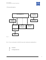
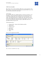
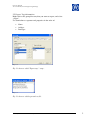
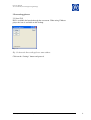
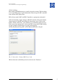
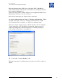
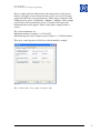
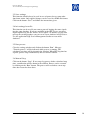
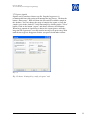
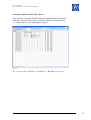
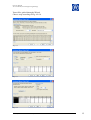
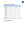
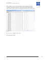
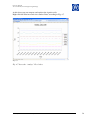
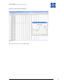
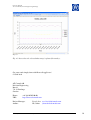
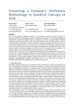
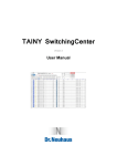
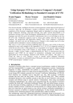
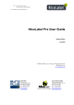
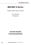
PLS
User Manual
Version 1.0.0.0
2007-06-09
TABLE OF CONTENTS
1 About PLS ........................................................................................................................ 1
1.1 General ....................................................................................................................... 1
1.2 System description ................................................................................................... 2
1.3 Getting started........................................................................................................... 3
2 OPC Server handle ......................................................................................................... 4
2.1 Init Tags...................................................................................................................... 4
2.2 Export Tag information ........................................................................................... 5
3 ProcessLoggServer.......................................................................................................... 6
3.1 Start PLS..................................................................................................................... 6
3.2 Init settings ................................................................................................................ 7
3.3 Save settings ............................................................................................................ 10
3.4 Init settings from file .............................................................................................. 10
3.5 Run process ............................................................................................................. 10
3.6 Manual Stop ............................................................................................................ 10
3.7 Export signals.......................................................................................................... 11
4 Analyze signals in MS Office Excel.......................................................................... 12
PLS User Manual
AF Consult AB, Division Engineering Borlange
1 About PLS
1.1 General
PLS (ProcessLoggServer) is an Electro engineering software tool,
developed for PLC (Programmable Logic Controller) process analyzes. The
software is developed in Sweden by AF Consult AB, Division Engineering
Borlange.
PLS works as a client to Beijer Electronics OPC Server. The OPC Server is
able to catch signals from different PLC vendors. Beijer OPC Server
supports the most common Controllers at market. Drivers for different PLC
vendors are available to be downloaded at their website. PLS version
1.0.0.0 only works with Beijer Electronics OPC Server. PLS logs signals
from the OPC environment and stores them into a database. Each log gets a
unique timestamp and a sample identity number. Signals can easily be
transferred into a text file for further analyze.
Author: Johan Ek
[email protected]
1
PLS User Manual
AF Consult AB, Division Engineering Borlange
1.2 System description
Processloggserver
Text file
(;) separated
Excel sheet
Tag file
(;) separated
OPC Server
XML-file
Configuration
Settings
SQL Server
Database
Driver
PLC
Fig. 1.1
Fig. 1.1 shows a description of the PLS system with configuration and data flows.
= Dataflow
= Configuration flow
Author: Johan Ek
[email protected]
2
PLS User Manual
AF Consult AB, Division Engineering Borlange
1.3 Getting started
Install PLS in Windows XP Operating system or run the software as a
preinstalled virtual machine. The virtual machine runs with VMware player
or Workstation application. VMware Player is a free desktop application
that lets you run a virtual machine on a Windows or Linux PC. For detailed
information read the (DVD):\Document\vmware_player200.pdf.
Either Software or Virtual pack must be chosen for your logging project.
The packs contain sufficient install information.
After setup is done, follow this manual for further management.
•
Software pack
Requires MS SQL Server 2005 installed at same computer (not
included in this pack).
Certain knowledge about SQL Server and Windows environment is
necessary.
•
Virtual pack
Contains a preinstalled PLS software.
Only requires VMware Player and WinRar application, (freeware
included in this package).
Author: Johan Ek
[email protected]
3
PLS User Manual
AF Consult AB, Division Engineering Borlange
2 OPC Server handle
This chapter only describes the Beijer OPC Server settings demands, when
PLS is used as a client. For detailed information about the OPC Server, read
the (DVD):\Document\OPC_manual.pdf.
2.1 Init Tags
Start the Beijer OPC Server. Right click Server directory and choose “new
Controller”. Give the controller a suitable name, (this name must also be
used by PLS). Right click at the Controller you created and choose “new
group”. Give the group directory a suitable name, (this name must also be
used by PLS). Right click at the group directory and choose “new tag”, init
your tags for measurement. For easy analyze by MS Office Excel, the
maximum amount of tags are 253.
Valid interpretation is:
•
•
•
•
•
•
•
unsigned 16-bit (choose this for Boolean and bit)
signed 16-bit
unsigned 32-bit
signed 32-bit
float 32-bit
Date & Time
string
Arrays are not supported by the PLS.
Fig. 2.1
Fig 2.1 shows a valid directory setup.
Author: Johan Ek
[email protected]
4
PLS User Manual
AF Consult AB, Division Engineering Borlange
2.2 Export Tag information
Right click at the group directory that you want to export, and select
“export”.
Use Semicolon as separator and properties in the order of:
•
•
•
Name
Address
DataType
Fig. 2.2
Fig 2.3 shows a valid ”Export tags” setup .
Fig. 2.3
Fig 2.3 shows a valid exported text file.
Author: Johan Ek
[email protected]
5
PLS User Manual
AF Consult AB, Division Engineering Borlange
3 ProcessLoggServer
3.1 Start PLS
PLS is available for launch through the start menu. When using VMware
player the icon is available on the desktop.
Fig. 3.1
Fig 3.1 shows the ProcessLoggServer start window.
Click on the “Settings” button and proceed.
Author: Johan Ek
[email protected]
6
PLS User Manual
AF Consult AB, Division Engineering Borlange
3.2 Init settings
PLS settings in RAM memory are totally clean after startup. The first thing
to do is give PLS proper signal information. Enter the given OPC controller
name and the OPC group name.
PLS will not work if OPC and PLS Controller or group name mismatch!
Click on the button “Apply changes to RAM” and then click on the button
“Import tag list to RAM” and follow the instructions given. Click on the
button “Check connection”, you will then get a connection status message.
If the connection attempt fails, check your OPC status and DCOM Settings
on your computer. Instructions are given in the help file
(DVD):\Document\Using OPC via DCOM with XP SP2 v1.10.pdf.
Fig. 3.2
Fig. 3.2 shows the “Settings OPC Server”tab.
When connection established proceed to the next tab “Database”.
Author: Johan Ek
[email protected]
7
PLS User Manual
AF Consult AB, Division Engineering Borlange
Enter the hostname where SQL Server is installed, (PLS v1.0.0.0 only
works with local host). Enter name of the database, (in virtual pack default
base is named “logDatabase”).
If you want more than the default database, use the application SQL Server
Management Studio to create more databases.
PLS will not work if host and database names mismatch!
Use proper Authentication, the default is “Windows Authentication”. When
using the virtual pack, always use “Windows Authentication”. If SQL
Server Authentication is required, use SQL Server Authentication.
Click on the button “Apply changes to RAM” and then click on the button
“Check connection”, you will then get a connection status message. If
connection attempt fails, check that SQL Server is running and proper
names of host and database is correctly given.
Fig. 3.3
Fig. 3.3 shows the “Settings Database”tab.
When the connection is established proceed to the next tab “Log config. &
export”.
Author: Johan Ek
[email protected]
8
PLS User Manual
AF Consult AB, Division Engineering Borlange
Enter a sample period in milliseconds and total quantity of log time in
minutes. No upper or lower limits for these values are reserved. Sample
period will affect the system performance. When using a computer with
2GHz processor speed, a landmark is: 1000 ms ≈ 200 tags. Lower sample
period reduces the total quantity of tags. Controller will not provide
information faster than approx. 50 ms, using shorter sample period is
useless.
The system limitations are:
Maximum number of samples: 2 147 483 647.
Maximum log time with a sample period of 50 ms is: 1 789 569 minutes.
This gives a total log time of 1242 days, which should be enough!
Fig. 3.4
Fig. 3.4 shows the “Log config. & export” tab.
Author: Johan Ek
[email protected]
9
PLS User Manual
AF Consult AB, Division Engineering Borlange
3.3 Save settings
This function should always be used in case of power loss or some other
shut down action. Only applied changes can be saved in a XML-file format.
Click on the button “Save” and follow the instructions given.
3.4 Init settings from file
This function can be used if you want to proceed logging the same signals
into the same database. If tags are modified in the OPC Server, you must
import updated tag list and “Delete saved signals” in database. If you want
to keep the existing database you can create a new database in SQL Server.
Use the application SQL Server Management Studio to create more
databases.
3.5 Run process
Close the settings window and click on the button “Run”. Message
“Transfer process” will be indicated while process is running. The
calculated stop time will be shown in the window. When PLS log time has
expired, process stops automatically and user will be notified.
3.6 Manual Stop
Click on the button “Stop”. If user stops log process before calculated stop
time, a notification will be shown in the window. Process can be restarted
by clicking on the “Run” button. The process will recalculate a new stop
time after restart has been done.
Author: Johan Ek
[email protected]
10
PLS User Manual
AF Consult AB, Division Engineering Borlange
3.7 Export signals
Signals can be transferred into a text file. Stop the log process is
recommended hence this action will interrupt the log process. Click on the
button “Show range”, PLS will show the first and last available sample in
the database. You can change the range of samples for export, as long the
samples exist in the database. Verify timestamps by clicking on the “select”
button. Click on the button “export” and choose directory and filename.
When large amount of signal data is chosen, the export process will take
long time. PLS generates a text file transfer message wile processing. Wait
until the message has disappeared before you proceed with other actions.
Fig. 3.5
Fig.3.5 shows “Settings Log config. & export” tab.
Author: Johan Ek
[email protected]
11
PLS User Manual
AF Consult AB, Division Engineering Borlange
4 Analyze signals in MS Office Excel
Copy the Excel document (DVD):\Document\signalAnalyze.xls into your
hard drive. Open the file and select “Edit Text Import” according to Fig.
4.1. Choose your text file with signals to import.
Fig. 4.1
Fig. 4.1 shows the predefined “signalAnalyze” MS Office Excel sheet.
Author: Johan Ek
[email protected]
12
PLS User Manual
AF Consult AB, Division Engineering Borlange
You will be guided through a Wizard.
Choose setup according to Fig. 4.2-4.4.
Fig. 4.2
Fig. 4.3
Fig. 4.4
Author: Johan Ek
[email protected]
13
PLS User Manual
AF Consult AB, Division Engineering Borlange
Signals now imported into Excel “rawData” sheet.
Fig. 4.5
Fig. 4.5 shows “rawData” Excel sheet.
Select the “calcData” sheet.
Author: Johan Ek
[email protected]
14
PLS User Manual
AF Consult AB, Division Engineering Borlange
The “calcData” sheet is used to recalculate values for plotting. Link the
“rawData” into this sheet and add a constant to the whole signal column
values. Signals will be separated in height when plotting in the analyze sheet.
Fig. 4.6
Fig. 4.6 shows “calcData” Excel sheet.
Select the analyze sheet.
Author: Johan Ek
[email protected]
15
PLS User Manual
AF Consult AB, Division Engineering Borlange
At this sheet you can compare and analyze the signals easily.
Right click the Plot Area and select Source Data, according to Fig. 4.7.
Fig. 4.7
Fig. 4.7 shows the “analyze” Excel sheet.
Author: Johan Ek
[email protected]
16
PLS User Manual
AF Consult AB, Division Engineering Borlange
Select new data range for analyze.
Fig. 4.8
Fig. 4.8 shows how to select data range.
Author: Johan Ek
[email protected]
17
PLS User Manual
AF Consult AB, Division Engineering Borlange
Fig. 4.9
Fig. 4.9 shows how the selected data range is plotted for analyze.
Get your work simply done with ProcessLoggServer!
// Good luck.
AF Consult AB
Division Engineering
Box 81
781 21 Borlange
Sweden
Phone:
URL:
+46 (0)10 505 00 00
http://www.afconsult.com
Project Manager:
Author:
Author: Johan Ek
Lissel, Ove [email protected]
Ek, Johan [email protected]
[email protected]
18