1
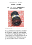
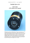
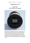
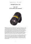
Handbook for the SXV-M25C
Issue 1 June 2004
Starlight Xpress Ltd
SXV-M25C SuperHAD 6Megapixel USB
One-Shot Colour CCD camera
User manual
Thank you for purchasing a Starlight Xpress CCD camera. We hope that you will be
very satisfied with the results.
The SXV-M25C is an advanced, very high-resolution cooled CCD camera, especially
designed for ‘One-Shot’ colour astronomical imaging. The features include a built-in,
fully programmable, USB 2 super-fast computer interface (USB 1.1 compatible), an
optional add-on autoguider output and integrated dual serial ports for filter wheel and
telescope control. The SXV-M25C uses a Sony ICX413AQ a very large ‘SuperHAD’
interline CCD, with 3040 x 2016 x 7.8uM pixels in a 23.4 x 15.6mm active area.
SuperHAD devices have excellent quantum efficiency in the visible spectrum, with a
broad spectral response peaking at around 60% in the green, and an extremely low
dark current, well below that of any comparable CCD currently available. The CCD
incorporates a ‘Bayer Matrix’ of Red, Green and Blue filters, deposited directly onto
the pixels and a downloaded image may be quickly converted into a full-colour
picture by application of the software provided.
1
Handbook for the SXV-M25C
Issue 1 June 2004
The USB 2 connection offers an excellent download speed, despite the very large
number of pixels to be digitised. The full-frame download time with a 2GHz machine
is approximately 16 seconds and binned 4x4 downloads take only 3 seconds, so
finding and centring are quick and easy in this mode. If you have only a USB 1.1
connection on your computer, the download time is longer, but is still quite fast at
around 30 seconds for a full resolution frame.
Please take a few minutes to study the contents of this manual, which will help you to
get the camera into operation quickly and without problems. I am sure that you want
to see some results as soon as possible, so please move on to the ‘Quick Start’ section,
which follows. A more detailed description of imaging techniques will be found in a
later part of this manual.
‘Quick Starting’ your SXV-M25C system
In the shipping container you will find the following items:
1) The SXV-M25C camera head.
2) A power supply module.
3) A power supply cable.
4) An SXV guider head.
5) A cable for the guider head to camera connection.
6) An RJ11 cable for connection of the guide output to the mount.
7) A USB2 camera cable.
8) An adaptor for 2” drawtubes and M42 Pentax thread lenses.
9) A disk with the SXV-M25C control software.
10) This manual.
Optional extra items include:
1) A serial port splitter adaptor and cable for filter wheels etc.
You will also need a PC computer with Windows 98, Windows Me, Windows 2000
or Windows XP installed (NOT Windows 95 or NT4). This machine must have at
least one USB port available and at least 128 Megs of memory. If you intend to view
the finished images on its screen, then you will also need a graphics card capable of
displaying an image with a minimum of 1024 x 768 pixels and 16,000,000 colours.
The very large image format means that viewing the entire image at full resolution is
not practical, but a 1600 x 1200 monitor resolution with 32 bit colour helps
considerably. A medium specification Pentium with between 1 and 2GHz processor
speed is ideal. USB 2 PCI and PCMCIA cards are readily available for upgrading a
USB 1.1 machine, if you want to achieve the best possible performance. Please note
that USB 2.0 operates at a very high speed and cannot operate over very long cables.
Five metres of good quality cable is the maximum normally permitted. Adding one, or
more, USB 2 ‘Hubs’ in line can extend this, if necessary. USB 1.1 is more tolerant
and will often work properly over a 15 metre lead without hubs.
2
Handbook for the SXV-M25C
Issue 1 June 2004
Installing the USB system:
First, find a free USB socket on your PC and plug in the USB cable. If you do not
have a USB capable computer, it is normally possible to install a USB 2 card into an
expansion slot. Almost all machines manufactured after 1996 provide a pair of USB
1.1 sockets on the rear panel and either of these may be used if USB 1.1 is
satisfactory. Please note that it may be necessary to enable your USB system in the
computer BIOS (the SETUP menu which can usually be accessed at start-up). Many
BIOS systems have the ability to disable ‘Plug and Play’ devices, such as the USB
ports, so please make sure that these are enabled.
The next operation is to run the USB installer from the CD ROM provided. Insert the
CD into the computer and run the ‘InstallSXV’ file which is found in the SXV-M25C
directory. This will install the following files:
1) ‘SXV_BlockIO_M25C.inf’ in C:\Windows\Inf\
2) ‘Generic.sys’ and ‘SXVIO.sys’ in C:\Windows\System32\Drivers\
If you cannot see the directories ‘C:\Windows\Inf’ and ‘Windows\System32\Drivers’,
this will be due to the setup of your Windows Explorer software. In this case, go to
the ‘Tools’ menu, followed by ‘Folder Options’ and select ‘View’. Now select ‘Show
hidden files and folders’ and make sure that the ‘Hide file extensions for known file
types’ and ‘Hide protected operating system files’ check boxes are NOT checked.
After this, the various directories and files should be visible.
It is now time to set up the USB device. Plug the USB cable into the camera and
observe the computer screen. After a brief delay, you should see an information box,
which reports that the computer has found a device called ‘Echo2’ and is looking for
the driver. If all is well, the cycle will complete within a couple of seconds, but it is
possible that you may have to prompt the system with the location of the ‘SXVIO.sys’
file (Windows\System32\Drivers). After another brief delay, the computer should say
that it has found a new USB2.0 device and is installing a ‘Starlight Xpress USB 2.0
CCD camera’. In some cases the installation will halt after the first stage and you will
need to restart the machine, or unplug and re-plug the USB lead to initiate the second
step.
3
Handbook for the SXV-M25C
Issue 1 June 2004
At the end of this process, the USB interface will be installed as a ‘BlockIOClass
device’ and the camera software will be able to access it. You can confirm that the
installation is complete by checking the status of the USB devices in the Windows
‘Device Manager’ (see above). Start up the Windows ‘Control Panel’ and select
‘System’. Now click on the tab labelled ‘Device Manager’ and all of the system
devices will be displayed in a list (see above). If the installation is successful, there
will be a diamond shaped symbol labelled ‘BlockIOClass’ and clicking on the ‘+’
sign will reveal it to be a ‘Starlight Xpress USB 2.0 SXV-M25C camera driver’ or
similar. If this device is faulty, try clicking on it and selecting ‘properties’ and then
‘update driver’. Following the on screen instructions will allow you to re-select the
correct inf file (SXV_BlockIO_M25C.inf) and driver file (SXVIO.sys), which should
fix the problem.
Adding the camera control software:
Now that the USB system is installed, the camera control program can be used to
operate your SXV-M25C. Copy the camera software files from the CD and paste
them into a suitable directory, such as ‘SXVM25’ on your computer’s C: drive. Your
directory should contain the files SXV_M25C_usb.exe, SXV_M25.hlp, bwcc32.dll
and wsc32.dll
Connecting the camera:
4
Handbook for the SXV-M25C
Issue 1 June 2004
The camera rear panel
Connect up the power supply and switch it on. You can start the ‘SXV_M25C’
software by double clicking on the icon and you should see the main menu and image
5
Handbook for the SXV-M25C
Issue 1 June 2004
panel appear. If the USB connection is OK, a message box will inform you of the
‘Handle’ number for the SXVIO interface and various other version details etc. The
main program window will now be seen.
If you press the ‘Camera’ Icon button at the top left, the program will warn you that
the ‘Program Defaults’ have not been set, but pressing ‘OK’ will allow you to
continue.
The camera default settings are not important for current purposes and may be left as
the software start-up values for now, but the warning message may be removed by
selecting ‘Set program defaults’ from the ‘File’ menu and then saving the defaults
window by pressing the ‘Save changes’ button. Once the camera control panel is seen,
you are all set to take your first images!
Recording your first image:
We now have the camera and computer set up to take pictures, but an optical system
is needed to project an image onto the CCD surface. You could use your telescope,
but this introduces additional complications, which are best avoided at this early
stage. There are two simple options, at least one of which is available to everyone:
1) Attach a standard ‘M42’ SLR camera lens to the SXV-M25C, using the 25mm
spacer to achieve the correct focal distance.
Or
2) Create a ‘Pin hole’ lens by sticking a sheet of aluminium baking foil over the end
of the 2” adaptor and pricking its centre with a small pin.
6
Handbook for the SXV-M25C
Issue 1 June 2004
If you use a normal lens, then stop it down to the smallest aperture number possible
(usually F22) as this will minimise focus problems and keep the light level reasonable
for daytime testing. The pin hole needs no such adjustments and will work
immediately, although somewhat fuzzily.
Point the camera + lens or pinhole towards a well-lit and clearly defined object some
distance away. Now click on the camera icon in the SXV_M25C software tool bar.
The camera control interface will open.
7
Handbook for the SXV-M25C
Issue 1 June 2004
You can now select an exposure time of 0.1 seconds, followed by pressing of the
‘Take Photo’ button.
After the exposure and download have completed (about 16 seconds) an image of
some kind will appear on the computer monitor. It will probably be poorly focused
and incorrectly exposed, but any sort of image is better than none! In the case of the
pinhole, all that you can experiment with is the exposure time, but a camera lens can
be adjusted for good focus and so you might want to try this to judge the image
quality that it is possible to achieve. With our 2 inch adaptor, most lenses come to
infinity focus at about midway through their normal focus adjustment range. The
large size of full resolution M25 images makes them difficult to visualise on most
computer screens and only about one third of the image may be visible. You can
‘scroll’ around the image using the sliders at the right and bottom edges, or select ‘Bin
high res. display’, as found in the ‘View’ menu. This reduces the displayed image to
half size and most of it will now be visible – the image data is NOT affected.
Various other exposure options are available, as can be seen in the picture of the
interface above. For example, you can ‘Bin’ the download 2x2, or more, to achieve
greater sensitivity and faster download, or enable ‘Continuous mode’ to see a steady
stream of images. The 4x4 or 6x4 binning modes give adequate resolution for finding
and offer a much faster download speed, along with a very high sensitivity.
‘Focus mode’ downloads a 128 x 128 segment of the image at high speed. The initial
position of the segment is central to the frame, but can be moved by selecting ‘Focus
frame centre’ in the ‘File’ menu and clicking the desired point with the mouse. The
focus window has an adjustable ‘contrast stretch’, controlled by the 12-16 bit slider.
The image will be normal if 16 bits is selected, while setting lower values will
increase the image brightness in inverse proportion.
8
Handbook for the SXV-M25C
Issue 1 June 2004
Please note that ONLY 1x1 binned images will decode to colour – the other modes
are for focusing and acquisition only.
If you cannot record any kind of image, please check the following points:
1) Ensure that the power indicator lamp is on and that the cables are properly home
in their sockets.
2) If the screen is completely white, the image may be greatly overexposed. Try a
shorter exposure time, or stop down your lens. See if covering the lens causes the
image to darken.
3) If the USB did not initialise properly, the camera start-up screen will tell you that
the connection is defective. Try switching off the power supply and unplugging the
USB cable. Now plug in the USB cable, followed by the power. This will re-load
the USB software and may fix the problem after restarting the SXV_M25C
program. Otherwise, check the device driver status, as previously described, and
re-install any drivers which appear to be defective.
4) If you cannot find any way of making the camera work, please try using it with
another computer. This will confirm that the camera is OK, or faulty, and you can
then decide how to proceed. Our guarantee ensures that any electrical faults are
corrected quickly and at no cost to the customer.
Converting your image to colour:
Once you have a recognisable image, it is quite easy to convert it to full colour. The
‘raw’ image will appear to have a fine grid distributed across it – this is the colour
filter matrix and the variations of pixel brightness encode the colour data which we
want to extract. Here is an enlarged section of a raw image:
Click on ‘Colour Synthesis’ in the main menu and you will see the synthesiser dialog.
9
Handbook for the SXV-M25C
Issue 1 June 2004
This includes various options for correcting the colour synthesis for variations in the
lighting conditions, filters etc. Briefly, these items perform the following functions:
1) Daylight Image? – If an unfiltered lens is used, the infra-red content of the
light will tend to produce a Green – Blue shift in the balance. A partial
correction of this bias is provided by selecting this option, but the best option
is to use an infra-red blocking filter when taking daylight shots (see 5 below).
2) Light Pollution Correction: - This option is for deep sky colour images,
where a strong colour bias is often present in the sky background. This option
attempts to return the background colour to a neutral grey.
3) Colour Smoothing Filter: - Applies a low pass filter to the colour data to
smooth out colour noise.
4) Apply Anti-Alias: - Runs a special filter over the colour data to remove
coloured artefacts around sharp edges. This is especially useful for cleaning up
erratically coloured star images.
5) IR Filter Used? – Sets the colour balance to allow for the loss of infra-red
content when using an IR blocking filter.
6) Stretching: - A selection of contrast-boosting options which are preset for
various subjects.
7) Remove Background: - This option will adjust the sky background brightness
to give an optimum background level.
8) High Pass filters: - Automatically sharpen the luminance data to emphasise
fine details. Most useful for sharpening planetary images but will also increase
the noise content.
For your first test images, I suggest that you turn on the Anti-Alias option and
possibly the ‘Daylight Image’ option.
10
Handbook for the SXV-M25C
Issue 1 June 2004
Now press the ‘Create Image’ button. After a couple of seconds, your raw mono
image will be replaced by a full colour version.
If the colour is roughly correct, then all is well. However, the colour decoding is
reliant on the filter pattern being properly registered with the processing software and
this can vary. If the colour is badly wrong, try opening the ‘Set program defaults’
dialog box and altering the ‘Pixel’ and ‘Line’ offsets. Reload the raw file and try
synthesis again. If it’s still not right, experiment with just a pixel offset or just a line
offset until the colour is good.
There is every reason to expect that the image will be reasonably well colour
balanced, but if it is not, you can adjust the colour in the ‘Set Colour Balance’ dialog
box (Under ‘Colour’ in the main menu).
11
Handbook for the SXV-M25C
Issue 1 June 2004
The colour balance controls seem complex, but are really quite easy to use. The most
useful controls are the ‘Start’ and ‘Saturation Factor’ settings. Saturation factor will
simply vary the colour intensity, without any alteration of the colour balance, but the
‘Start’ settings for each colour will alter the colour rendering of the dimmer parts of
the image. As most astronomical images are badly affected by light pollution, which
affects the dimmer background colours in particular, the start point settings are
particularly helpful for correcting this. If you move the start point of the Red
histogram a few points to the right and click on ‘Apply’, the new image will have
LESS red in the background and will appear more Cyan. Similarly, if you move the
Green start point to the right, the image will appear more Magenta and moving the
blue start point will turn it more Yellow. Do not move the start points beyond the start
of the main burst of histogram data, or you will introduce colour errors into low
saturation parts of the image. Just move the sliders by small amounts in the clear area
below the main peak, until the background is nicely balanced.
In some cases, the histograms may all start a long way above zero (usually in astro.
images with a lot of light pollution). In this case, slide the start point settings for all
colours until they are equally distant from the beginning of the colour data, but quite
close to it. This will both correct the colour balance (apart from any fine tweaks) and
increase the colour saturation.
In some images, the colour data may be balanced differently in the highlights and
shadows. For example, the dark areas may be quite neutral in colour, but the
highlights may be bluish in tint. This indicates a ‘slope error’ in one or more colours
and, in this example it is caused by the blue data increasing too quickly when
compared with the red and green data. To correct for this, the other histogram sliders
may be used as slope adjusters. In the case of the excess blue, try increasing the top
end (Max) value to greater than 255 (300 max is allowed). This will reduce the blue
slope and result in a more yellowish rendition. Alternatively, you can increase both
the red and green slopes by setting the upper red and green sliders below 255.
Other image enhancements:
Your first image may be satisfactory, but it is unlikely to be as clear and sharp as it
could be. Improved focusing and exposure timing may correct these shortcomings,
12
Handbook for the SXV-M25C
Issue 1 June 2004
and you may like to try them before applying any image enhancement with the
software. However, there will come a point when you say, “That’s the best that I can
get” and you will want to experiment with the effects of image processing. In the case
of daylight images, the processing options are many, but there are few that will
improve the picture in a useful way. The most useful of these are the ‘Normal
Contrast Stretch’, ‘Power law stretch’ and the ‘High Pass Low Power’ filter.
The ‘Contrast’ routines are used to brighten (or dull) the image highlights and
shadows. A ‘Normal’ stretch is a simple linear operation, where two pointers (the
‘black’ and ‘white’ limits) can be set at either side of the image histogram and used to
define new start and end points. The image data is then mathematically modified so
that any pixels that are to the left of the ‘black’ pointer are set to black and any pixels
to the right of the ‘white’ pointer are set to white. The pixels with values between the
pointers are modified to fit the new brightness distribution. Try experimenting with
the pointer positions until the image has a pleasing brightness and ‘crispness’. Most
daylight pictures suffer from having too much ‘Gamma’ (a way of referring to the
contrast response curve) and look unnaturally contrasty. Applying a ‘Power law’
stretch of about 0.5 power will often make them look better, although you will
probably need to follow this with a ‘Normal’ stretch to darken the shadow regions.
The high pass filter gives a moderate improvement in the image sharpness, and this
can be very effective on daylight images. Too much high pass filtering results in dark
borders around well-defined features and will increase the noise in an image to
unacceptable levels, but the Low Power filter is close to optimum and gives a nicely
sharpened picture, as above.
At this point, you will have a working knowledge of how to take and process an SXVM25C image. It is time to move on to astronomical imaging, which has its own
unique set of problems!
*********************************************************************
Astronomical Imaging with the SXV-M25C
1) Getting the image onto the CCD:
The SXV-M25 has a very large CCD chip and this will not work well with many
commonly available telescopes, such as Schmidt-Cassegrain and Newtonian
reflectors. At the very least, the corners of the image will be severely vignetted by the
narrow optical path and you are likely to see just a round ‘porthole’ in the middle of
the image field. As you are the owner of an M25, I am assuming that you already
have a suitable optical system available, but as a general guideline, a short focus
apochromatic refractor is an ideal choice. Many of these are expensive, but are
essential if you are to achieve top quality results. I use a Takahashi FSQ106 (106mm
aperture, 500mm focal length), but the Sky90 and Televue NP101 are other excellent
choices. You need a well corrected flat field which has been designed to cover at least
a 35mm film frame – preferably a 57mm format frame. Some high quality camera
lenses will give good results, but many of these have poor infra-red and UV
correction that can cause halos around bright stars and result in soft images. An
IR/UV blocking filter can help a great deal, at some cost to sensitivity, and the IDAS
light pollution rejection filter will perform this task very well. I recommend the IDAS
13
Handbook for the SXV-M25C
Issue 1 June 2004
filter for the reduction of light pollution and aberration effects and it is a valuable
accessory to any imaging system.
It is fairly easy to find the correct focus setting for the camera when using a standard
SLR lens, but quite a different matter when the SXV-M25C is attached to a telescope!
The problem is that most telescopes have a large range of focus adjustment and the
CCD needs to be quite close to the correct position before you can discern details well
enough to optimise the focus setting. Fortunately, the relatively short focal length and
wide field of view associated with suitable telescopes for the M25, makes this easier
than with longer focus systems and smaller CCD chips. Attach the M25 to your
optical system with either a T thread adaptor or by clamping to the 2 inch diameter
nose piece provided with the camera. Any filters should be at least 48mm in diameter
and mounted just ahead of the camera (or on the objective, where appropriate).
As a guide, most CCD astronomers try to maintain an image scale of about 2 arc
seconds per pixel for deep sky images. This matches the telescope resolution to the
CCD resolution and avoids ‘undersampling’ the image, which can result in square
stars and other unwanted effects. To calculate the focal length required for this
condition to exist, you can use the following simple equation:
F = Pixel size * 205920 / Resolution (in arc seconds)
In the case of the SXV-M25C and a 2 arc seconds per pixel resolution, we get
F = 0.0074 * 205920 / 2 = 761mm
This is a very rough guide and so the 500mm FSQ is well suited, as are most other
short focus refractors.
Achieving a good focus:
Point the telescope at a bright star and focus the optics to an estimate of the correct
focus position. A good way to determine this is to space a sheet of frosted glass,
plastic or grease-proofed paper about 18mm behind the drawtube aperture and focus
for a sharp star image on the screen. Substituting the camera for the screen will put a
fairly well focused star image onto the CCD.
The SXV_M25C has a focus routine that will repeatedly download and display a 128
x 128 pixel segment of the image at relatively high speed. This focus window may be
positioned anywhere in the camera field and can be displayed with an adjustable
degree of automatic contrast stretching (for focusing on faint stars). To use this mode,
start up the software and select the SXV camera interface (File menu). Set the camera
mode to Binned 4x4 and select an exposure time of 1 second. Press ‘Take Picture’ and
wait for the image to download. There is a good chance that your selected star will
appear somewhere within the image frame and it should be close to a sharp focus. If
the focus is still poor, then it may appear as a pale disk of light, often with a dark
centre (the secondary mirror shadow in an SCT, or Newtonian). Now select the ‘File’
menu again and click on ‘Focus frame centre’; you can now use the mouse pointer to
click on the star image and the new focus frame co-ordinates will be displayed. Now
return to the camera interface window and click on ‘Start’ in the Focus frame. The
14
Handbook for the SXV-M25C
Issue 1 June 2004
computer will now display a continuous series of 128 x 128 pixel images in the focus
window and you should see your selected star appear somewhere close to the centre.
A ‘peak value’ (the value of the brightest pixel) will also be shown in the adjacent text
box and this can be used as an indication of the focus accuracy. Although the peak
value is sensitive to vibration and seeing, it tends towards a maximum as the focus is
optimised. Carefully adjust the focus control on your telescope until the image is as
sharp as possible and the peak value reaches a maximum. Wait for any vibration to
die down before accepting the reading as reliable and watch out for bursts of bad
seeing, which reduce the apparent focus quality. Quite often, the peak value will
increase to the point where it is ‘off scale’ at 4095 and in this case you must halt the
focus sequence and select a shorter exposure if you wish to use the peak value as an
indicator. Once you have determined the position of best focus, you might like to
mark the drawtube barrel so that the correct setting can be found quickly in future.
Although you can reach a good focus by the above method, many observers prefer to
use additional aids, such as Hartmann masks (an objective cover with two or three
spaced holes) or diffraction bars (narrow parallel rods across the telescope aperture).
These make the point of precise focus easier to determine by creating ‘double images’
or bright diffraction spikes around stars, which merge at the setting of exact focus.
The 12-16 bit slider control allows you to adjust the contrast of the focus frame for
best visibility of the star image. It defaults to maximum stretch (12 bits), which is
generally ideal for stars, but a lower stretch value is better for focusing on planets.
Taking your first astronomical image:
I will assume that you are now set up with a focused camera attached to a telescope
with an operating sidereal drive. If so, you are now in a position to take a moderately
long exposure of some interesting deep-sky astronomical object. As most drives are
not very accurate beyond a minute or two of exposure time, I suggest that you find a
fairly bright object to image, such as M42, M13, M27 or M57. There are many others
to choose from, but these are good examples.
Use the finder to align on your chosen object and then centre accurately by using the
focus frame and a short exposure of between 1 and 5 seconds. The ’12-16 bit’ slider
in the focus frame allows you to adjust the image contrast if you find that the object is
too faint with a short exposure. Once properly centred and focused, take an exposure
of about 60 seconds, and observe the result. Initially, the image may appear rather
barren and show only a few stars, however, there is a great deal of data hidden from
view. You can get to see a lot of this, without affecting the image data, if you go to
the ‘View’ menu and select ‘Auto Contrast Stretch Image’. The faint image data will
then appear in considerable detail and I think that you will be impressed by the result!
If you are happy with the image, go to the ‘File’ menu and save it as a Tiff file in a
convenient directory.
15
Handbook for the SXV-M25C
Issue 1 June 2004
M42 from a 5 minute exposure at F5 with the FSQ106 + IDAS filter
Most competitive brands of CCD camera require a ‘dark frame’ to be subtracted from
your images to achieve the best results. A dark frame is simply a picture which was
taken with the same exposure as your ‘light frame’, but with the telescope objective
covered, so that no light can enter. It records only the ‘hot pixels’ and thermal
gradients of your CCD, so that these defects are largely removed when the dark frame
is subtracted from the light frame. The SXV-M25C CCD is quite different from those
used in other brands of camera and generates an extremely low level of dark noise.
Indeed, it is so low that subtracting a dark frame can actually INCREASE the noise in
your images! This is because the statistical noise of the dark frame can exceed the
‘pattern noise’ from warm pixels and hence add to that of the subtracted result. If your
test pictures have an exposure time of less than about 30 minutes (as above), then
don’t bother with a dark frame, just ‘kill’ any hot pixels with your processing
software. In SXV-M25C, the ‘Median filter’ can do this, but other software (e.g.
Maxim DL) will provide a ‘hot pixel killer’ that can be mapped to specific locations
in the image.
If you feel that dark frame really is necessary, please proceed as follows:
To take a dark frame, just cover the telescope objective with the lens cap and take
another exposure of the same length as that of the light frame. This image will be a
picture of the dark signal generated during your exposure and it should be saved with
your image for use in processing the picture. If many such darks are recorded and
averaged together, the statistical noise will be reduced, but the gains to be had are
rather small compared with the effort involved.
As variations in ambient temperature will affect the dark signal, it is best to take the
dark frames within a few minutes of capturing your images. For the same reason, it is
not wise to use ‘old’ dark frames if you want the best possible results, however, some
software allows you to scale library dark frames to match the image (e.g. AstroArt
and Maxim DL) and this can be useful as a time saver.
16
Handbook for the SXV-M25C
Issue 1 June 2004
‘Flat fields’ are often recommended for optimising the results from your CCD
camera. The purpose of a flat field is to compensate for uneven illumination and
sensitivity of the CCD. In the case of the very large chip of the SXV-M25, it is likely
that you will need to use flats to eliminate optical vignetting and so it is a good idea to
get used to taking and using them. There are several ways that a flat field can be
recorded, but it surprisingly difficult to generate a ‘perfect’ flat field image. In
essence, you need to take a picture of an evenly illuminated surface so that the
resulting picture contains only the dust shadows and optical shading of the CCD field.
This can then be divided into the image data and used to cancel out the defects.
Achieving the even illumination necessary for a good flat field is quite difficult. Some
users construct a special ‘light box’ to drop over the objective of the ‘scope and this is
probably the best method, but some easier techniques will work. One common
method is to stretch a white fabric sheet across the telescope aperture and take an
image of the daylight sky with this in place. A white ‘Tee shirt’ is the classic item for
use as a diffuser and so such a flat is often known as a ‘Tee shirt flat’.
Flat fields are images, which display only the variations of illumination and
sensitivity of the CCD and are used to mathematically modify a wanted image in such
a way that the errors are removed. Common flat field errors are due to dust motes on
the camera window and vignetting effects in the optical system of the telescope. Dust
motes act as ‘inverse pinholes’ and cast out-of-focus images of the telescope aperture
onto the CCD chip, where they appear as shadow ‘do-nuts’. Most optical systems
show some vignetting at the edges of the field, especially when focal reducers are
used. This causes a brighter centre to show in images, especially when there is a lot of
sky light to illuminate the field.
If dust motes are your main problem, it is best to clean the camera window, rather
than to rely on a flat field to remove the do-nuts. Flat fields always increase the noise
in an image and so physical dust removal is the best option. If you have serious
vignetting, first check whether the optical system can be improved.
If you really do need to use a flat field for image correction, then it must be taken with
care. It is most important that the optical system MUST NOT be disturbed between
taking your original images and taking the flat field. Any relative changes of focus
and rotation etc. will upset the match between flat field and image and the result will
be poor correction of the errors.
Most imaging sessions begin or end in twilight and so the dusk or dawn sky can
provide a distributed source of light for a flat field. However, using the sky directly is
likely to result in recording many unwanted stars, or patches of cloud etc., so a
diffuser needs to be added to the telescope. A Tee shirt can be used, but an ideal
material is Mylar plastic drafting film, obtained from an office supplies warehouse. It
is strong and water resistant and can be easily replaced if damaged. Stretch a piece of
the film loosely across the aperture of your telescope and point the instrument high in
the sky, to avoid any gradient in the light near the horizon. Now take several images
with exposure times adjusted to give a bright, but not overloaded, picture. A
histogram peaking at around 128 is ideal. Averaging flat fields together is a good way
to reduce their noise contribution and so recording 4, or more, images is a good idea.
17
Handbook for the SXV-M25C
Issue 1 June 2004
To use your flat fields, they must first have a dark frame subtracted. Although this
may appear to be unimportant with such brightly lit and short exposures, there is the
‘bias offset’ of the camera in each image and this can produce an error in the final
correction. As we are mainly interested in the bias, any very short exposure dark
frame will give a good result. The dark subtracted images should then be averaged
together before use.
After the above procedures have been executed, the flat field will be ready for use.
Load up your image for processing, subtract the dark frame and then select ‘Apply
flat field’ in the ‘Merge’ menu. The result should be an image with very few signs of
the original artefacts and you can then process it in the normal way
Processing a deep-sky image:
The following instructions include the subtraction of a dark frame, but this may be
regarded as optional.
1) Make sure the ‘Auto Contrast Stretch’ is switched off and load your image into the
SXV_M25C program. Select ‘Merge’ and then ‘Subtract Dark Frame’. Pick the
appropriate dark frame and the software will then remove the dark signal from your
image, leaving it somewhat darker and slightly smoother than before.
2) The next step is to process the image into colour, but you may find that the
application of a gentle contrast stretch to the image before synthesis will improve the
colour result. Don’t overdo the stretch, as the colour range can then exceed the
dynamic range available, leading to un-correctable colour errors. Keep a copy of the
original file – just in case! Set the colour synthesiser to apply the anti-alias filter and
then run it.
3) The resulting image will probably still look faint and dull, with a pale orange or
green background due to light pollution. Try using the ‘Start point’ adjustment in the
Colour balance menu to get something close to a neutral background colour. It is now
time to process the ‘luminance’ (brightness and contrast) of the image to get the best
visual appearance. First, use the ‘Normal’ contrast stretch to darken the background
by setting the ‘Black’ slider just below the main peak of the histogram. Alternatively,
you can use the ‘Remove Background’ icon button to let the software decide on the
best setting. This will greatly reduce the background brightness and the image will
begin to look rather more attractive, if dark. You can now try brightening the
highlights with another ‘Normal’ stretch, in which you bring down the ‘White’ slider
to just above the main image peak. The best setting for this is rather more difficult to
guess and you may need several attempts before the result is ideal. Just use the ‘Undo
last filter’ function, if necessary, to correct a mistake. In many cases, a ‘Normal’
contrast stretch will give a good result, but may ‘burn out’ the bright regions and
leave the faint parts of the image rather lacking in brightness. To combat this, many
imagers will use a combination of ‘Normal’ and ‘Non-linear’ contrast stretches. The
best settings are different for different objects, but performing a non-linear or power
law stretch, followed by normalising the background to black with a normal stretch, is
the usual procedure.
18
Handbook for the SXV-M25C
Issue 1 June 2004
4) The image will now look quite impressive and I hope that you are pleased with
your first efforts!
Further small refinements are usually possible and you will become expert at judging
the best way to achieve these as your experience increases. As a rough guide, the
‘Filters’ menu can be used to sharpen, soften or noise reduce the image. Strong ‘High
Pass’ filters are usually not a good idea with deep sky images, as the noise will be
strongly increased and dark rings will appear around the stars, but a ‘Median’ filter
can remove odd speckles (hot pixels) and a mild ‘Unsharp Mask’ (Radius 3, Power 1)
will sharpen without too much increase in noise. If you have a copy of ‘Paint Shop
Pro’, the ‘Edge preserving smooth’ filter will work rather well as a noise reducer and
the ‘Despeckle’ filter will remove warm pixels quite effectively. To use these, export
your image as a Tiff file so that Paint Shop can accept it. Paint Shop (or Photo Shop)
also provides a convenient way of cropping, rotating and printing your finished
images. The following examples are typical of 40 minute exposures at F5, using an
IDAS filter on an FSQ106.
19
Handbook for the SXV-M25C
Issue 1 June 2004
Other things to try include summing several images for a better signal to noise ratio.
This MUST be done AFTER colour synthesis, as summing raw images is very likely
to destroy the filter grid pattern and so prevent the creation of a proper colour image.
Summing can be done in the ‘Merge’ menu and involves loading the first processed
image, selecting a reference point (a star) then loading the second image and finding
the same star with the mouse. Once the reference is selected, you can either add
directly, or average the images together. Averaging is generally better, as you are less
likely to saturate the highlights of the picture. The signal-to-noise ratio will improve
20
Handbook for the SXV-M25C
Issue 1 June 2004
at a rate proportional to the square root of the number of summations (summing 4
images will double the signal-to-noise), but different exposures must be used.
Summing an image with itself will not change the S/N ratio! Another recent addition
to the range of highly effective image enhancing software is a program called ‘Neat
Image’. There is a free demo version for download at:
http://www.neatimage.com/download.html
Although I have concentrated on the use of a telescope for deep-sky imaging, do not
forget that you have the option of using an ordinary camera lens for impressive widefield shots! A good quality 200mm F3.5 lens with an infrared blocking filter will yield
very nice images of large objects, such as M31, M42, M45 etc. If you cannot obtain a
large IR blocker for the front of the lens, it is quite acceptable to place a small one
behind the lens, inside the adaptor tube. You can even try using a light pollution filter
to bring out nebulae, reduce light pollution and sharpen the star images. The Hutech
IDAS types are particularly effective with a colour camera.
Adjusting the focal plane of the camera:
With a very wide field camera, it is very likely that the CCD will not be accurately
parallel to the telescope focal plane. This may be seen as a variation in the focus
quality from one side of the image to the other, or as distortion of the stars towards
one side. Because of this possibility, we have provided an array of antagonistic screws
around the front plate of the SXV-M25. These may be adjusted with an Allen key and
locked at the correct angle to make the focal surfaces co-planar. To make the
adjustment, first slacken all three of the set screws so that the front plate is free to tilt.
The spring washers behind the plate will resist any movement, but turning the main
fixing screws will tilt the plate and allow you to experiment with the alignment. Once
the focus is equally good across the entire image field, turn the set screws to lock the
plate into the correct position.
21
Handbook for the SXV-M25C
Issue 1 June 2004
Taking pictures of the planets:
The SXV-M25 is not designed as a planetary camera, but it can be used quite
successfully in the ‘sub-frame’ mode. Planetary imaging is in many ways quite
different from deep sky imaging. Most deep sky objects are faint and relatively large,
so a short focal length and a long exposure are needed, while planets are bright and
very small, needing long focal lengths and short exposures. High resolution is critical
to achieving good results and a suitable focal length will be of the order of 5000mm,
or more. An SCT with a 3 or 5x Barlow lens will provide a reasonable image scale for
the planets – any vignetting is unimportant as only the field centre is required.
Many camera users comment on the difficulty of finding the correct focus when
taking pictures of Jupiter etc. This is usually due to poor seeing conditions, which are
only too common, but may also be due in part to poor collimation of your telescope.
Please ensure that the optics are properly aligned as shown by star testing, or by using
one of the patent collimation aids that are widely available. It is also better to use a
star for initial focusing, as planetary detail is difficult to judge in bad seeing. Although
the star will also suffer from blurring, the eye can more easily gauge when the most
compact blur has been achieved!
You could begin by imaging lunar craters, or the planets, Jupiter, Saturn or Mars. The
rapid variations of seeing which accompany planetary imaging will ruin the definition
of about 95% of your images and so I recommend setting the camera to run in
‘Autosave’ mode. This will automatically take a sequence of images and save them
with sequential file names in your ‘Autosave’ directory. Dozens of images will be
saved, but only one or two will be satisfactory for further processing. The ‘Subframe’
mode of the SXV will be found useful for limiting the wasted area and reducing the
download time of small planetary images.
To start the Autosave process, call up the SXV Camera Interface and select the
‘Continuous Mode’ check box at the top (make sure the rest are unchecked). Now
check the ‘Autosave Image’ checkbox near the bottom of the window. If you now
click on ‘Take Picture’ the automatic sequence will begin and will not stop until you
press a computer key. The images will be saved in FITs format with sequential names
such as ‘Img23, Img24….’ and will be found in the ‘Autosave’ directory (or a subdirectory of Autosave, set up in the program defaults menu).
The exposure time needed for good planetary images is such that the image histogram
has a peak value at around 200 and does not extend much above 220 (Ignore the
major peak near zero, due to the dark background). If you use too short an exposure
time, the image noise level will be increased, and if too long a time is used you will
saturate the highlights and cause white patches on the image. With the recommended
focal length, Jupiter and Mars will both need an exposure time of between 0.1 and 1
seconds and Saturn will need between 0.5 and 2 seconds.
Processing a planetary image:
Planetary images have one major advantage over deep sky images, when you come to
process them – they are MUCH brighter, with a correspondingly better signal to noise
22
Handbook for the SXV-M25C
Issue 1 June 2004
ratio. This means that aggressive sharpening filters may be used without making the
result look very noisy and so some of the effects of poor seeing can be neutralised.
Try applying an ‘Unsharp Mask’ filter with a radius of 5 and a power of 5. This will
greatly increase the visibility of any detail on the planet, but the optimum radius and
power will have to be determined by experiment.
Jupiter after an ‘Unsharp mask’
In general terms, the larger the image and the worse the seeing, then the wider the
radius for best results. My Jupiter shots are usually about one tenth of the height of
the CCD frame and I find that the ‘radius 5, power 5’ values are good for most
average seeing conditions. If you have exceptionally good conditions, then a
reduction to R=3, P=3 will probably give a more natural look to the image, as too
large a radius and power tends to outline edges with dark or bright borders.
As a finishing touch, the application of a Median filter or a Weighted Mean Low Pass
filter can be useful to smooth out the high frequency noise after a strong Unsharp
Mask.
As with deep-sky images, it is advantageous to sum colour planetary images together
to improve the signal to noise ratio. In this case, the ‘averaging’ option should always
be used, or the result is likely to exceed the dynamic range of the software and
saturate the highlights. Aligning the images is always something of a problem, as
there are rarely any stars to use when imaging the planets, but Jupiter’s satellites can
be useful reference points. Otherwise, you will have to find a well-defined feature on
the planet, or estimate where the centre of the disk is located. Some more
sophisticated software can automatically align planetary images and you may find
these programs to be very useful (e.g. Registax’).
*********************************************************************
Using the add-on autoguider:
23
Handbook for the SXV-M25C
Issue 1 June 2004
A very useful accessory is the add-on autoguider head, which takes its power and
control signals directly from the SXV camera, via the 18 way socket on its rear panel.
The autoguider is only 1.25” in diameter and has a video style ‘CS’ mount thread in
its nose, so video lenses may be attached. The guider may be used with either an offaxis prism assembly mounted in front of the SXV camera, or with a separate guide
telescope, rigidly mounted alongside your imaging telescope. I personally use it with
an 80mm aperture F5, inexpensive refractor as a guide ‘scope, but a shorter focal
length lens will make more guide stars available in any given region of sky (See the
picture below).
To use the autoguider, first orient it so that the connector plug is roughly parallel to
the declination axis of your mount. This is not absolutely essential, as the training
routine will learn the angle of the head and compensate for it, but it is easier to
understand the motion of the guide star if the guider frame is aligned with the RA and
Dec axes. Now connect the head to the SXV camera, using the 18 way connector lead,
including the port divider box, if it is to be used.
The recommended way of connecting the autoguider output to the mount is to use an
RJ11 telephone lead between the socket on the SXV camera and the autoguider input
of your mount. This output is ‘active low’ (i.e. the control relays pull the guider inputs
down to zero volts when applying a guide correction) and matches most of the
autoguider inputs on commercial mounts. If ‘active high’ inputs are needed, or a very
low control voltage drop is essential, then you will need to add a Starlight Xpress
‘relay box’ between the guider output and the input to the mount. Please contact your
local distributor if a relay box is required. Some mounts (Vixen, for example) use a
similar guider input socket, but have re-arranged connections. Details are given on our
web pages at the end of the ‘STAR2000’ section.
24
Handbook for the SXV-M25C
Issue 1 June 2004
The autoguider installed on a 80mm refractor guide ‘scope in the author’s garden
To use the autoguider, please proceed as follows:
1) Having started the SXV-M25C software, open the autoguider control panel by
clicking on the autoguider menu button.
25
Handbook for the SXV-M25C
Issue 1 June 2004
The autoguider control panel with a guide star selected
2) Press the ‘Start’ button and a series of 1 second exposure guider images will
begin to appear in the picture frame. If the images look too dim, use the
‘Stretch Image’ slider to increase its contrast and brightness until the noise
begins to be visible.
3) If you haven’t focused the guider lens or ‘scope, move the mount until a bright
star is visible on the guider image and then adjust the focus until it is as sharp
as possible.
4) At this point, you may want to test the guiding control by pressing the manual
‘Move Telescope’ buttons at the bottom left corner of the control panel. You
can watch the position of any stars in the guider image and confirm that they
move in response to the buttons. The movement should be slow if the correct
guiding rate is selected on your mount (typically 2x sidereal). Adjust this, if
necessary.
5) Move the mount until the required object for imaging is properly framed in the
main CCD image (leave the guider menu and use the main camera control
panel, as necessary).
6) Re-open the guider control panel, start imaging and try to locate a clearly
visible guide star. If necessary, make adjustments to the guide telescope or offaxis guider until one is found.
7) Press ‘Stop’ and then press ‘Select Guide Star’. Use the mouse to left click on
the selected star and a green cross will highlight it and the co-ordinates will
appear in the text boxes above the image window.
8) The various guiding rate defaults, listed on the right-hand side of the control
panel, are unlikely to be perfect for your particular telescope and mount. You
have the option of manually selecting values, or asking the software to attempt
to determine what they should be. This is done by pressing the ‘Train’ button
and waiting for the software to complete a sequence of automatic moves and
26
Handbook for the SXV-M25C
Issue 1 June 2004
calculations. The training will also determine the angle at which the guide
camera is oriented with respect to the RA and Dec axes. If you do not wish to
train the system at this time, the default values of 6 pixels per second will
serve as a starting point.
9) Now press ‘Go to main camera’ and the guider control panel will be replaced
by the camera control panel. Set the required exposure time for the image (say
5 minutes) and press the ‘Autoguide next image’ button. The autoguider
window will reappear and, after a few seconds, you should see error values
appearing in the text windows at the top. The guide star will be fairly close to
the green cross, although not necessarily accurately centred, and you should
see the power/ guide LED on the rear of the camera brighten and change
colour with each correction.
10) If the star begins to drift away from the cross, despite the corrections being
made, the chances are that the N/S and/or E/W directions are set wrongly.
Judge which axis is incorrectly set by observing the direction of the drift and
then stop the exposure by pressing ‘Esc’. Open the guider control panel and
check the appropriate swap box(es). After this operation, you will probably
need to find the guide star again by taking a guider image and reselecting the
star, as before. Now return to the main camera menu and try the ‘Autoguide
next image’ button again.
11) Once guiding is taking place without problems, the main exposure can be
allowed to finish and, if all is well, you should see an image with tiny circular
stars.
If the stars are not circular, you may need to alter the guiding parameters, or
investigate the rigidity and drive performance of your mount. A lot of information
can be deduced by watching the behaviour of the guide star in the guider frame. If
it is continually moving between two locations, either side of the green cross, then
the RA or Dec pixels per second value is set too low. The higher these values are
set, the gentler the guiding becomes. Too low a value will cause an overaggressive correction to be made and result in oscillation of the star position
between two points.
Another source of guiding errors can be a too accurately balanced telescope
mount! Good balance can result in the telescope mount ‘bouncing’ between the
gear teeth as corrections are made. A simple fix is to add a weight of about 0.5kg
(1 pound) on the eastern end of the declination axis, so that there is always some
pressure acting against the gear teeth.
Getting a good result from an autoguider will often entail a lot of detective work
to eliminate the sources of gear error, telescope flexure, mirror shift etc., but the
final result is well worth the effort!
*********************************************************************
Using the built-in serial ports
The SXV-M25C incorporates two fast serial ports for use with external accessories.
The ports are available on 5 pins of the 18 way connector that is provided for the
autoguider and may be accessed by plugging in a ‘serial port divider box’. The divider
27
Handbook for the SXV-M25C
Issue 1 June 2004
box and cables are available as an accessory and may be chained in series with the
autoguider cable, when the guider is in use, or may be used on its own.
The two serial connections are in the form of standard RS232 PC style plugs and
provide TX, RX and Ground connections at RS232 levels. Access is via commands
sent through the USB connection and, at the time of writing, is limited to any serial
controls that are provided by the SXV software. It is expected that many more
functions will be added as the software is upgraded.
*********************************************************************
Other features of the SXV-M25C hardware and software
‘Slew & Sum’ imaging:
The SXV-M25C can be used in an automatic image-stacking mode, called ‘Slew &
Sum’. The camera is set to take several sequential exposures, which are automatically
‘slewed’ into alignment and then summed together by the software. This mode can
help to overcome a poor RA drive by summing images that have exposure times
shorter than the drive error period. The resulting image has more noise than a single
exposure of the same total length, but this method of imaging is still an effective way
of making long exposures without a guider.
To take an S&S image, go to the camera interface window and select an exposure
time for one image of the sequence. Do not use a very short exposure time, as the
read-out noise will become dominant. About 30 seconds is a reasonable minimum.
Now go to the ‘Multiple Exposure Options’ and select a number of exposures to take.
You can also select to average the images, rather than adding them, and there is a
‘Alternative Slew Mode’ available, which uses the correlation of image areas, rather
than a single star. This mode can be better in dense star fields.
Another option is ‘Auto remove dark frame’. This is advisable with S&S images, as
the slewing will mis-register the images with a single dark frame that is applied to the
finished sequence. To use this option, you will need a dark frame, taken with the same
exposure time as a single image from the sequence. This is stored on drive C with the
name ‘dark.def’
Now click on ‘Take Picture’ and the sequence will begin.
Using the ‘Binned’ modes:
Up to this point, I have assumed that the full resolution, imaging mode is being used.
This is essential for colour imaging, but it will often provide more resolution than the
optical system, or the seeing, allows. ‘Binned 2x2’ mode sums groups of 4 pixels into
one output pixel, thus creating a 696 x 520 pixel image with 4 times the effective
sensitivity. Using 2x2 binning, you can considerably improve the sensitivity of the
SXV-M25C without losing a great deal of resolving power, so you may like to use
this mode to capture many faint deep-sky objects in monochrome. Other binning
modes (3x3 and 4x4) are available and will further increase the image brightness and
28
Handbook for the SXV-M25C
Issue 1 June 2004
reduce its resolution. However, generally, these are more useful for finding faint
objects, than for imaging, as the colour information is lost in all these modes.
.
*********************************************************************
The SXV-M25C accessory ports
The SXV-M25C is provided with two ports for use with accessories. The Autoguider
output port is a 6 way RJ11 socket, which is compatible with the standard autoguider
input of most telescope mounts. It provides 4 active-low opto-isolator outputs and a
common return line, capable of sinking a minimum of 5mA per output. This socket
may be used for telescope control if the SXV-M25C is employed as an autoguider,
but is primarily intended to be the control output for the optional add-on autoguider
camera head, available for use with the SXV-M25C.
The high density parallel port socket provides both control and power for the add-on
autoguider, but also includes a pair of serial ports for use with other devices.
29
Handbook for the SXV-M25C
Issue 1 June 2004
*********************************************************************
Camera maintenance:
Very little maintenance is needed to keep the SXV-M25C in excellent operating
order, however two problems, which are common to all CCD equipment, might show
up on occasion. These are dust particles and condensation.
Removing Dust:
1) Dust can be deposited on either the optical window (not a big problem to cure), or
on the CCD faceplate (difficult to eliminate entirely). When small particles collect on
the window they may not be noticed at all on deep sky (small F ratio) images, as they
will be very much out of focus. However, if a powerful contrast boost of the image is
carried out, they may well begin to show as the shadow ‘Do-nuts’ or disks mentioned
earlier. Images taken with a large F ratio optical system are more likely to be affected
by such dirt, owing to the smaller and sharper shadows that they cast. There is no
great difficulty in removing such particles on the outside surface by the careful use of
a lens cleaning cloth or ‘air duster’ and so you should have little trouble with this
aspect of maintenance. Dust on the CCD faceplate is a much greater nuisance, as it
casts very sharply defined and dark shadows and it entails dismantling the camera to
get rid of it! To clean the CCD you will need a good quality lens cloth (no silicone) or
tissues and some high-grade isopropyl alcohol. A very suitable cloth is the ‘MicroFibre’ type marketed by PENTAX etc., and suitable alcohol is available from Tandy
(Radio Shack) etc. as tape head cleaning fluid. A bright light and a strong
watchmakers eyeglass will also be found to be essential.
Procedure:
1) Disconnect the lead from the camera head and remove it from the telescope. Place
it on a table with the optical window facing downward.
2) Remove the two M3 screws from the camera back plate and ease the plate out of
the camera body. Unplug the power lead from the camera PCB.
3) Withdraw the body cylinder and unscrew the two long spacer pillars from the heat
sink plate assembly.
4) The entire camera electronic assembly can now be lifted away from the camera
front barrel and the CCD will be readily accessible. Note that a layer of white heatsink compound is applied to the periphery of the heat sink disc and this should be left
undisturbed by subsequent operations.
5) You can now closely examine the CCD faceplate under the spotlight using the
watchmaker's glass when any dust motes will show clearly. If there is only an odd
particle or two and the CCD is otherwise clean, carefully brush away the dust with a
corner of your lens cloth. A smeared or very dusty CCD will need a few drops of
alcohol to clean thoroughly and you may have to make several attempts before the
surface is free of contamination. One gentle wipe from one end to the other, with no
return stroke, will be found to be the most effective action. DO NOT rub vigorously
and be very careful to avoid scratching the window.
30
Handbook for the SXV-M25C
Issue 1 June 2004
6) Before re-assembly, make certain that the inside surface of the front window is also
clean, and then carefully replace the camera front barrel and screw it into place. (If the
heat sink seal is disturbed, renew it with fresh compound before reassembling).
7) Replace all the camera parts in reverse order and the job is done.
Dealing with condensation:
The SXV-M25C is designed to avoid condensation by minimising the volume of air
trapped within the CCD cavity and by preventing moisture ingress. This normally
works very well, but storage of the camera in a humid location can lead to the trapped
air becoming moist by diffusion through the optical window mounting thread etc. and
can result in condensation on the CCD window. If this becomes a problem, try storing
the camera in a warm, dry place, or in a plastic lunch box containing a sachet of silica
gel desiccant.
N.B. DO NOT leave the camera switched on for long periods between uses. The
cold CCD will collect ice by slow diffusion through any small leaks and this will
become corrosive water on the cooler and CCD pins when the power is removed. If
substantial amounts of moisture are seen, dismantle the camera and dry it
thoroughly.
*********************************************************************
Alternative Software
Although we hope that you will be satisfied with our ‘SXV_M25C_USB’ software,
other companies are offering alternative programs with more powerful processing
functions. The most active and successful of these is ‘AstroArt’ by MSB software.
You can purchase AstroArt from many dealers Worldwide and more information may
be obtained from their web site at http://www.msb-astroart.com
‘Maxim DL’ is another popular choice and you can find out more by visiting
http://www.cyanogen.com
*********************************************************************
Some details of the camera and CCD characteristics
CCD type: Sony ICX413AK SuperHAD progressive scan imager with RGBG
Bayer colour filter matrix.
CCD size:
Active area 23.4mm x 15.6mm
CCD pixels: 3044 x 2016 pixel array. Each pixel is 7.4 x 7.4uM square
Well depth: Full res. mode approx. 30,000e.
Mean visual QE: Approx. 25% effective, 60% for pixels at peak response
Useful spectral response: 360nM – 1100nM
31
Handbook for the SXV-M25C
Issue 1 June 2004
Readout noise: Approx. 7e RMS typical, 12e max.
Back focal distance: The CCD is approximately 18mm from the barrel front.
Camera size: 75mm diameter x 100mm long
Dear Observer,
Thank you for purchasing a Starlight Xpress CCD Imaging System. We are confident that you will gain
much satisfaction from this equipment, but please read carefully the accompanying instruction manual
to ensure that you achieve the best performance that is capable of providing.
As with most sophisticated equipment a certain amount of routine maintenance is necessary to keep the
equipment operating at its optimum performance. The maintenance has been kept to a minimum, and is
fully described in the manual.
In the unfortunate instance when the equipment does not perform as expected might we recommend
that you first study the fault finding information supplied. If this does not remedy the problem, then
contact Starlight Xpress for further advice. Our message board service on the Starlight Xpress web site
will often provide solutions to any problems.
The equipment is covered by a 12-month guarantee covering faulty design, material or workmanship in
addition to any statutory Consumer Rights of Purchasers.
CONDITIONS OF GUARANTEE
1) The equipment shall only be used for normal purposes described in the standard operating
instructions, and within the relevant safety standards of the country where the equipment is used.
2) Repairs under guarantee will be free of charge providing proof of purchase is produced, and that the
equipment is returned to the Service Agent at the Purchaser’s expense and risk, and that the equipment
proves to be defective.
3) The guarantee shall not apply to equipment damaged by fire, accident, wear an tear, misuse,
unauthorised repairs, or modified in any way whatsoever, or damage suffered in transit to or from the
Purchaser.
4) The Purchaser’s sole and exclusive rights under this guarantee is for repair, or at our discretion the
replacement of the equipment or any part thereof, and no remedy to consequential loss or damage
whatsoever.
5) This guarantee shall not apply to components that have a naturally limited life.
6) Starlight Xpress’s decision in all matters is final, and any faulty component which has been replaced
will become the property of Starlight Xpress Ltd.
For further info. or advice, please call:
Mr Michael Hattey,
Starlight Xpress Ltd.,
Briar House, Foxley Green Farm,
Ascot Road, Holyport,
Berkshire,
England. SL6 3LA
Tel: 01628 777126
Fax: 01628 580411
e-mail: [email protected]
32
Handbook for the SXV-M25C
Web site: http://www.starlight-xpress.co.uk
33
Issue 1 June 2004