1
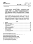
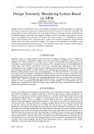
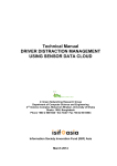
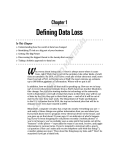
ISSN: 2277-3754 ISO 9001:2008 Certified International Journal of Engineering and Innovative Technology (IJEIT) Volume 3, Issue 6, December 2013 Design and Implementation of Online Patient Monitoring System Using Cortex-M3 Core 1 D.VIJAYA KUMAR 1, K.SRINIVAS 2, B.SRINIVAS 3 M.TECH (E.S.), Dept of E.C.E, Aurora’s Technological & Research Institute,[email protected] ,2 Assistant Professor, Dept of E.C.E, Aurora’s Technological & Research Institute, [email protected] 3 Assistant Professor, Dept of E.C.E, Aurora’s Technological & Research Institute, [email protected] Abstract- Computer communication systems and especially the Internet are playing an important role in the daily life. Using this knowledge many applications are imaginable. Home automation, utility meters, security systems can be easily monitored using either special front-end software or a standard internet browser client from anywhere around the world [2]. Web access functionality is embedded in a device to enable low cost widely accessible and enhance user interface functions for the device [1]. A web server in the device provides access to the user interface functions for the device through a device web page [9]. Create HTML webpage and linkup HTML page with the ADC output values. Interface GSM module with cortex-M3 using UART. Developing UART drivers to send SMS through GSM Develop an Ethernet driver for packet transfer. B. The Block diagram of the project Keywords- Critical care, Vital signs, Ethernet, web page, TCP/IP protocols. I. INTRODUCTION Online data monitoring system is one of the promising trends in the era of computing in today’s system automation industry. The proposed project is one such attempt of designing online patient condition monitoring system using Cortex-M3 core[5]. In this project we will develop Ethernet device drivers for Cortex-M3 core to transmit the monitored sensor data (patient condition) to internet. The System can complete the remote monitoring and maintenance operations of equipment through the network using Web browser. By introducing Internet into control network, it is possible to break through the spatial temporal restriction of traditional control network and effectively achieve remote sensing, monitoring and realtime controlling of equipments. The main essence of this project is to design and implement online data monitoring system using ARM CORTEX M3 CORE and TCP/IP Ethernet connection for data monitoring applications [2]. The real time analog voltages are converted into corresponding digital values using the ADC pins inbuilt in LPC 1768 Cortex M-3 and transfer them to the internet through Ethernet. In this project, if the patient condition is not good then a message will be send to the doctor through GSM [11]. Fig: 1 Block diagram The hardware part of project includes the following components: LPC 1768 H-Plus Ex Header Board Sensors– Heartbeat, Temperature, blood pressure Ethernet Cable GSM module USB-Power Supply Adapter The software tools used in the project are as follows: Keil IDE Flash Magic Hotspot Connectify III. PROJECT CONTENTS II. OVERVIEW OF THE PROJECT A. Cotex m3 core processor The LPC1768 are ARM Cortex-M3 based microcontrollers for embedded applications featuring a high level of integration and low power consumption. The ARM Cortex-M3 is a next generation core that offers system enhancements such as enhanced debug A. Objectives of the project Understanding the architecture of ARM Cortex M3 Core. Design and develop an ADC conversion driver for external input signal to ADC Pin using UART. 197 ISSN: 2277-3754 ISO 9001:2008 Certified International Journal of Engineering and Innovative Technology (IJEIT) Volume 3, Issue 6, December 2013 features and a higher level of support block integration. Teletex, through they are not integral parts of the GSM standard. The LPC1768 operate at CPU frequencies of up to 100 Bearer services or Data services, which are MHz [5]. The LPC1769 operates at CPU frequencies of limited to layers 1, 2 and 3 of the OSI reference up to 120 MHz. The ARM Cortex-M3 CPU incorporates model. Data may be transmitted using either a a 3-stage pipeline and uses Harvard architecture with transparent mode or nontransparent mode. separate local Instruction and data buses as well as a third Supplementary ISDN services, are digital in bus for peripherals. The ARM Cortex-M3 CPU also nature, and include call diversion, closed user includes an internal prefetch unit that supports group, and caller identification. Supplementary speculative branching. The peripheral complement of the services also include the short message LPC1768 includes up to 512 kB of flash memory, up to 64 kB of data memory, Ethernet MAC, USB service (SMS). Device/Host/OTG interface, 8-channel general purpose DMA controller, 4 UARTs, 2 CAN channels, 2 SSP 2 .Short Message Service controllers, SPI interface, 3 I2C-bus interfaces, 2-input SMS stands for Short Message Service. It is a plus 2-output I2S-bus interface, 8-channel 12-bit ADC, technology that enables the sending and receiving of 10-bit DAC, motor control PWM, Quadrature Encoder message between mobile phones. SMS first appeared in interface, four general purpose timers, 6-output general Europe in 1992. It was included in the GSM (Global purpose PWM, ultra-low power Real-Time Clock (RTC) System for Mobile Communication) standards right at with separate battery supply, and up to 70 general the beginning [11]. Later it was ported to wireless purpose I/O pins. The LPC1768 are pin-compatible to the technologies like CDMA and TDMA. The GSM and 100-pin LPC236x ARM7-based microcontroller [5]. SMS standards were originally developed by ETSI. ETSI is the abbreviation for European Telecommunication Standard Institute. Now the 3GPP (Third Generation Partnership Project) is responsible for the development and maintenance of the GSM and SMS standards [11]. One SMS message can contain at most 140 bytes (1120 bits) of data, so one SMS message can contain up to: 160 characters if 7-bit character encoding is used. (7-bit character encoding is suitable for encoding Latin characters like English alphabets). 70 characters if 16-bit Unicode UCS2 character encoding is used. (SMS text messages containing non-Latin characters like Chinese character should use 16-bit character encoding.) Once the message is sent the message is received by SMSC, which must then get it to the appropriate mobile device. To do this the SMSC sends a SMS request to Home Location Register (HLR) to find the roaming customer. Once HLR receives the request, it responds to the SMSC with the subscriber’s status: 1 Inactive or active 2 Where subscriber is roaming. If the response is “inactive“, then the SMSC will hold onto the message for a period of time. When the subscriber access his device, the HLR sends a SMS notification to the SMSC and the SMSC will attempt delivery. The SMSC transfer the message in a Short Message Delivery Point to Point format to the serving system. The system pages the device, and if it responds, the message gets delivered. The SMSC receives verification that the message was received by the end user, then categorizes the message as “sent” and will not attempt to send again. SMS provides a mechanism for transmitting short message to and from wireless devices. The service makes Fig 2: LPC1768 H-plus ex board B. GSM Technology GSM is a global system for mobile communication GSM is an international digital cellular telecommunication [11]. The GSM standard was released by ETSI (European Standard Telecommunication Standard) back in 1989. The first commercial services were launched in 1991 and after its early introduction in Europe; the standard went global in 1992. Since then, GSM has become the most widely adopted and fastestgrowing digital cellular standard, and it is positioned to become the world’s dominant cellular standard. Today’s second-generation GSM networks deliver high quality and secure mobile voice and data services (such as SMS/ Text Messaging) with full roaming capabilities across the world. 1. GSM Services GSM services follow ISDN guidelines and classified as either tele services or data services. Tele services may be divided into three major categories: Telephone services, include emergency calling and facsimile. GSM also supports Videotex and 198 ISSN: 2277-3754 ISO 9001:2008 Certified International Journal of Engineering and Innovative Technology (IJEIT) Volume 3, Issue 6, December 2013 use of an SMSC, which acts as a store and forward D. procedure of the project system for short messages. One major advantage of SMS 1 .Algorithm of project is that it is supported by 100% GSM mobile phones. 1. Start Almost all subscription plans provided by wireless 2. Include header files carriers include inexpensive SMS messaging service 3. Declare and initialize variables 4. Read sensor values in the form of analog values C. Ethernet 5. Convert these analog values into digital form My main application module regarding our project is using in-built ADC to transfer the Digital Values which are obtained from 6. Derive formulae for different sensors of each the output of in built ADC (AD 0.5) to a web browser patient with the help of Ethernet and TCP/IP Protocol and 7. Send these sensor readings to HTML page display those values for another person in another 8. Send patient – 1 condition through GSM location with the help of Wi-Fi. In this, I used two 9. Send patient-2 condition through GSM protocols: CSMA/CD Protocol for Ethernet Wire 10. Send all sensor values to Ethernet port Transfer and TCP/IP Protocol for uploading these values 11. Repeat steps 4 to 10. to a Webpage and to display those in other PC’s.In this report, first I would like to give the readers a brief idea 2 .Flow chart of the project about the Ethernet and its protocol followed by a clear description about how packets can be transferred in Ethernet and how TCP/IP protocol helps our project in data acquisition. 1 .Ethernet Ethernet is a family of computer networking technologies for local area networks (LANs). Ethernet was commercially introduced in 1980 and standardized in 1985 as IEEE 802.3. Ethernet has largely replaced competing wired LAN technologies. The Ethernet standards comprise several wiring and signaling variants of the OSI physical layer in use with Ethernet [2]. Ethernet is commonly mistaken to be a synonym for Internet. It is true that the technologies that power the Internet power Ethernet as well but there is a major distinction between the two– while the Internet is global in its nature, Ethernet is a local area network, which generally covers only a single building or premises that are close to each other. Modern technologies made it possible for Ethernet networks to span tens of kilometers but this doesn't change the local nature of Ethernet. Ethernet allows many computers to connect to one another into a network. This is done with the help of special Ethernet hardware and Ethernet protocols [2]. Ethernet is a local area technology, with networks traditionally operating within a single building, connecting devices in close proximity. At most, Ethernet devices could have only a few hundred meters of cable between them, making it impractical to connect geographically dispersed locations .Modern advancements have increased these distances considerably, allowing Ethernet networks to span tens of kilometers. In networking, the term protocol refers to a set of rules that govern communications. Protocols are to computers what language is to humans. Since this article is in English, to understand it you must be able to read English. Similarly, for two devices on a network to successfully communicate, they must both understand the same protocols [2]. Fig 3: flowchart of project 199 ISSN: 2277-3754 ISO 9001:2008 Certified International Journal of Engineering and Innovative Technology (IJEIT) Volume 3, Issue 6, December 2013 want to send. Copies bytes from MCU-memory to frame 3. Procedure of the project port. Our project main motto is to display the ADC values Next module is to write an easyweb-API function on the Server’s Webpage via Ethernet cable interfacing using TCP/IP. For this, initialize the LAN-controller, and further can be transferred over TCP network layer by reset flags, starts timer-ISR. Listen on creating a HTTP Server and display those values on 'MyIP:TCPLocalPort' for an incoming connection and try client’s Webpage and if the patient conditions are cross to establish a connection between 'MyIP:TCPLocalPort' the limitations then a message will be sent to doctor by and 'RemoteIP:TCPRemotePort' then releases the using GSM technology. In this, first the sensors of receive-buffer and allows easy web to store new data. patient1& patient2 take the patients readings and then Rx-buffer must be released periodically, else the other these analog values are given to the ADC of LPC1768 TCP get no ACKs for the data it sent. Transmit data HPLUS Ex board. The ADC will convert these analog stored in 'TCP_TX_BUF'. Number of bytes to transmit values into digital values .so for this the ADC API was must have been written to 'TCPTxDataCount' and datadeveloped and next I need to develop the Ethernet API. countMUSTNOTexceed'MAX_TCP_TX_DATA_SIZE'. The step by step execution of our Ethernet_Adc source Easyweb's 'main()'-function must be called from user code is described in this section: program periodically (the often - the better) and it For this project to implement successfully, I need to handles network, TCP/IP-stack and user events. design source codes for Ethernet packet driver for use Most important part is to check for the IP type (IPv4), with LAN controller, implementing the TCP/IP stack and get IP’s frame length, get source IP, get destination IP, providing a simple Application Interface to the user and etc. and this tcpip.c links the broadcasted message finally implementing a dynamic HTTP Server by using received from the MAC address to the given IP address the easyweb –API.I started with designing of source code via tcp/ip protocol i.e., it links Ethernet and the HTTP for Ethernet packet driver (EMAC.c). The algorithm of server webpage. Coming to the main part of the program, this source code is described below: I need to implement a dynamic HTTP-server by using the I am using here the DP83848 Ethernet card. First, we easy web-API. Here I initialized the page count and the declared some functions to write and read from the ADC values to 100 and 0. For giving a timing interval of Physical device and wait until each operation is being 10 ms for refreshing the webpage, I used Systick Timer completed. Then, add function to initialize the Rx Interrupt. It is enabled in the NVIC using the appropriate Descriptors and set EMAC Receive Descriptor Registers. Interrupt Set Enable register. Systick timer is intended to In the same fashion, write a function to initialize the Tx generate a fixed 10ms interrupt for use by the OS. This Descriptors and EMAC Transmit Descriptor Registers. timer is assigned to GPIO2 -> 2.0 pin with XOR The remaining part describes about configuring portoperation to toggle led 0. pins for use with LAN-controller, reset it and send the Next, coming to the main part, I started with setup of configuration-sequence.Next function is initializing the core clock and generated interrupt every 10ms. For the EMAC and a modified function to access EMAC. First ADC input, I connected Potentiometer to AD0.5 pin i.e,. step is initializing the EMAC Ethernet controller. In this to P1.31, set clock frequency to 12 MHz and enable this initialization, I need to power up the Ethernet, Enable P1 pin. Clear HTTP-server's flag register and this HTTP Ethernet pins. If mac module id is same as old mac server function is described later. Set port we want to module id, then P1.6 should be set otherwise no need to listen to (Local port= HTTP port). Here, I created an set. Reset all emac internal modules and add a delay after infinite while loop and in it I write a command to listen reset. Next step is initializing mac control registers. Put for incoming TCP-connection, to handle network and the DP83848C in reset mode. Here I need to do some easyweb stack and finally implement a HTTP Server. conditions for the following: Check if this is a The project’s final module is to design a HTTP server. DP83848C PHY and Configure the PHY device. This function implements a very simple dynamic HTTPConfigure Full/Half Duplex mode. Configure server. It waits until connected, and then sends a HTTP100MBit/10MBit mode. Next, Set the Ethernet MAC header and the HTML-code stored in memory. Before Address registers. sending, it replaces some special strings with dynamic At the start I had declared functions for Tx and Rx values (A/D converter results). It establishes a server descriptors. Those should be initialized here. Next, connection and checks if somebody had connected to our Receive Broadcast and Perfect Match Packets. Enable IP, checks if remote TCP sends data and throw it away. EMAC interrupts. Reset all interrupts. Enable receive In this way bytes of information can be transferred from and transmit mode of MAC Ethernet core. It reads words Ethernet to the HTTP server webpage. This whole in an order from Rx Buffer and Rx Frame port and copies content can be only viewed in a HTML webpage. For them to the MCU Memory. Reads the length of the this, I designed a html webpage. The ADC values are received Ethernet frame and checks if the destination displayed in the analog voltage scale on this webpage address is a broadcast message or not. It requests space in and at the bottom of the webpage; you can see a page EMAC memory for storing an outgoing frame and check count. if Ethernet controller is ready to accept the frame we 200 ISSN: 2277-3754 ISO 9001:2008 Certified International Journal of Engineering and Innovative Technology (IJEIT) Volume 3, Issue 6, December 2013 Finally, with the help of Hotspot Connectify software, Cortex M-3.By using these values derive formulae for I created a server and if any PC connected to this private different sensors of each patient and based on this values network, they are able to see this webpage by typing the the message will be send to mobile through GSM. If the particular IP address in their Internet browser. patient1 temperature is high then a message is send to mobile through GSM immediately that is shown in the IV. RESULTS AND OUTPUTS above figure 5. A. Data Monitoring System displayed on a webpage V. CONCLUSION & FUTURESCOPE The real time analog voltages are converted into The project “design and implementation of online corresponding digital values using the ADC pins inbuilt patient monitoring system using cortex-m3 core” has in LPC 1768 Cortex M-3 and transfer them to the been successfully designed and tested. It has been internet through Ethernet and by using tcp/ip protocols developed by integrating features of all the hardware these values are stored in specified address. When we components and software used. Presence of every enter that address in the browser then those values are module has been reasoned out and placed carefully thus display on the browser. This webpage has analog contributing to the best working of the unit. Secondly, readings ranging from 0V to 3.3V. For every 2 seconds, using highly advanced lpc1768 board and with the help the webpage can be refreshed automatically and Page of growing technology the project has been successfully Count can be displayed below the analog output. The implemented. Data Monitoring System displayed on a webpage is The Porting of FreeRTOS Kernel onto the Cortex M3 shown in above fig 4. Core Processor for Multitasking .So by this FreeRTOS we will be getting the multitasking operation in our project and we will be controlling patient condition when the vital signs are exceed their ranges by giving some treatment with robotics. These are the future scopes of this project. REFERENCES [1] Jean J Labrosse, “Embedded Systems Building Blocks” R&D Books, pp 61-100. [2] An Axelson “Embedded Ethernet and Internet Complete” Lakeview Research LLC, 2003. [3] Josephy Yiu “The Definitive Guide to ARM Cortex M3” Newness,©2007. [4] Pont, Michael J “Embedded C”, Pearson Education ©2007. [5] “LPC 17xx User Manual”, NXP Semiconductors. Fig: 4. Data Monitoring System displayed on a webpage. [6] “Web Convert User Manual”, Precidia Technologies, ©2002. B. Receiving message through GSM [7] HTML Coding from w3schools.com. [8] Description about entire Lpc1768 and Ethernet form the Data sheet of Lpc17xx manual. [9] Creating HTML page from www.artima.com . [10] Arul Prabahar A, Brahmanandha Prabhu, “Development of a Distributed Data Collection System based on Embedded Ethernet” 978-1-4244-9799-71111$26.00 ©2011 IEEE. [11] “GSM basics History” on Tutorial point, Wikipedia and private line. Fig 5.Receiving message through GSM The analog voltages are converted into corresponding digital values using the ADC pins inbuilt in LPC 1768 201