1
10
10.1
Argon Truster Operation
Sonic Orifice
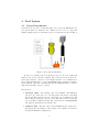
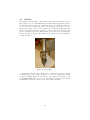
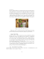
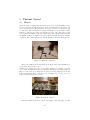
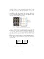
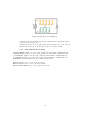
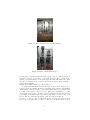
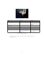
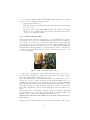
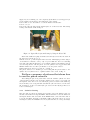
The sonic orifice is the part in the thruster that enables you to control the argon mass
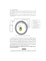
flow rate. The physics behind the sonic orifice is quite basic (see Fig. 59). It is a plate
with a tiny hole that is drilled in its center. The plate is placed in an NPT connection
so any gas flow within the NPT connection will flow through the tiny hole. The NPT
connections are connected in between the Argon valve and the tube that’s going into
the tank. Since the pressure difference is very large (about one atmosphere on one side
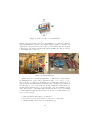
and vacuum on the other side) the flow will be a sonic flow. The male NPT connection
pushes the disk (gray disk in Fig. 59) and keeps it from moving. The 3 orange flexible
washers are there as a soft buffer between the male NPT connection and the disk.
This way the gas can flow only through the tiny hole.
Figure 59: Sonic Orifice Structure
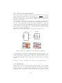
We are interested in the mass flow rate so the relation between the hole size, the
sonic velocity and the mass flow rate is:
ṁ = ρAVs
(4)
√
The sonic speed (Vs ) is temperature dependent through Vs = γRT . The orifice’s
area (A) is known and the gas density (ρ) is pressure and temperature dependent
through the ideal gas law.
P − PT ank
(5)
RT
Remember that R is species dependent according to R = R0 /Mw . Also PT ank ' 0
Plugging Eq. 5 into Eq. 4 gives the following relation for ṁ:
ρ=
γ 1/2
(6)
RT
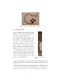
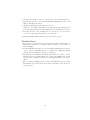
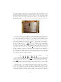
The temperature is measured by a thermocouple at the NPT connection and is
usually around T = 260 K because of the gas expansion.
The sonic orifice has a known area.
The mass flow rate is controlled by changing the pressure at the argon gauge side. It
ṁ = P A
69