1
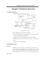
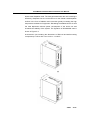
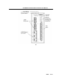
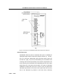
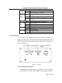
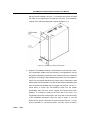
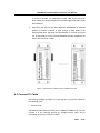
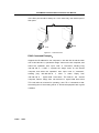
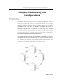
SICOM3005 Industrial Ethernet
Switch
User Manual
Kyland Technology Co., Ltd.
SICOM3005 Industrial Ethernet Switch
User Manual
Copyright © 2009 Kyland Technology CO., LTD.
All rights reserved.
No part of this documentation may be excerpted, reproduced, translated,
annotated or duplicated, in any form or by any means without the prior written
permission of KYLAND Corporation.
Publisher: Kyland Technology CO., LTD.
Address:Chongxin Creative Building, Shixing East Road 18#, Shijingshan
District, Beijing, China
Website:http://www.kyland.cn
postcode:100041
Tel:(+86-10)88796676
FAX:(+86-10)88796678
E-mail:[email protected]
Version:V1, Jul. 2009
No.:27030050-10
Preface
SICOM3005 is a integrated serial server function programmable industrial
Ethernet switch specially designed by KYLAND Technology CO., LTD. for
industrial applications. SICOM3005, an integrated optical communication
equipment, integrates Ethernet with serial data transmission and realizes
the
conversion
high-performance
of
serial
switch
protocols
engine,
solid
to
Ethernet
and
closed
protocols.
case
Its
design,
high-efficient single-ribbed casing for heat dissipation without using fans,
overcurrent, overvoltage and EMC protection at power input side, and
excellent EMC protection of RJ45 port, RS232 and RS485 data port allow
SICOM3005 working in harsh and dangerous industrial environments. The
redundant function of optical fiber network and redundant power input
highly guarantee reliable system operation.
The User Manual for SICOM3005 Industrial Ethernet Switch mainly
introduces the information on technical principles, performance indexes,
installation and commissioning etc. to provide users with references in
startup, expansion and routine maintenance. It also can be used as a
practical teaching material to learn and understand SICOM3005 industrial
Ethernet Switch.
This manual mainly includes the following contents:
Chapter 1 Overview and system features of SICOM3005 Industrial
Ethernet Switch
Chapter 2 Performance and service functions of SICOM3005 Industrial
Ethernet Switch
Chapter 3 Hardware structure of SICOM3005 Industrial Ethernet Switch
Chapter 4 Installation of SICOM3005 Industrial Ethernet Switch
Chapter 5 Test methods for SICOM3005 Industrial Ethernet Switch
Chapter 6 Networking modes and system configuration of SICOM3005
Industrial Ethernet Switch
Appendix A Twisted pair cable and pin distribution rules of SICOM3005
Industrial Ethernet Switch
Appendix B Cable types and specifications of SICOM3005 Industrial
Ethernet Switch
Statement: As product and technology are upgraded and improved
constantly, the contents of this document may not completely accord
with the actual product. For product upgrading information, please
visit our company’s website or directly contact with our business
representatives.
Notice for Safety Operation
This product offers reliable performances as long as it is used within the
designed scope. Artificial damage or destruction of the equipment should
be avoided.
z
Carefully read this manual and well preserve this manual for future
reference;
z
Do not place the equipments near water sources or damp places;
z
Do not place anything on power cable which should be placed in
unreachable places;
z
Do not tie or wrap the cable to prevent fire.
z
Power connectors and connectors for other equipments should be
firmly interconnected and frequently checked.
In the following cases, please immediately disconnect the power
supply and contact with our company:
1.
Water gets into the equipments;
2.
Equipment damage or shell breakage;
3.
Abnormal operation conditions of equipment or the demonstrated
performances have changed;
4.
z
The equipment emits odor, smoke or noise.
Please keep optical fiber plugs and sockets clean. During operation of
equipments, do not stare directly into the cross section of optical fiber;
z
Please keep the equipment clean; if necessary, wipe the equipment
with soft cotton cloth;
z
Do not repair the equipment by yourself, unless it is clearly specified in
the manual.
Explanation of Warning Marks:
This manual uses two kinds of noticeable warning signs to arouse special
attention of users during operation. The implications of these signs are as
follows:
Warning: pay special attention to the notes behind the
mark, improper operation will result in serious damage of
the switch or injury of operation personnel.
Caution, attention, warning, danger: remind the positions
requiring attention during operation.
CONTENTS
Chapter 1 System Overview ............................................................................................................ 8
1.1 Product Overview............................................................................................................................. 8
1.2 System Features.............................................................................................................................. 9
1.3 Packing list and unpacking check ............................................................................................... 10
Chapter 2 Performance Specification......................................................................................... 12
2.1 System Specification...................................................................................................................... 12
2.2 Service Interface............................................................................................................................. 13
2.3 Service Function............................................................................................................................. 14
Chapter 3 Hardware Structure ...................................................................................................... 18
3.1 System Structure ............................................................................................................................ 18
3.2 Switch Structure.............................................................................................................................. 18
Chapter 4 Hardware Installation................................................................................................... 29
4.1 Installation Requirements.............................................................................................................. 29
4.2 Install Switch ................................................................................................................................ 29
4.3 Connect TP Cable .......................................................................................................................... 33
4.4 Connect F/O cables ....................................................................................................................... 34
4.5 Cable Wiring.................................................................................................................................... 34
Chapter 5 Test Methods.................................................................................................................. 37
5.1 Self Inspection ................................................................................................................................ 37
5.2 Test RJ45 Port ................................................................................................................................ 37
5.3 Test Fiber Port................................................................................................................................. 37
Chapter 6 Networking and Configurations................................................................................ 39
6.1 Networking ...................................................................................................................................... 39
6.2 Configurations................................................................................................................................. 40
Appendix A Twisted-pair and Pin Distribution.......................................................................... 42
Appendix B Cable Type and Specifications .............................................................................. 44
Appendix C Glossary ...................................................................................................................... 46
-PAGE
- 7/56-
SICOM3016 Industrial Ethernet Switch User Manual
Chapter 1 System Overview
1.1 Product Overview
SICOM3005 is a integrated serial server function programmable industrial
Ethernet switch specially designed by KYLAND Technology CO., LTD. for
industrial applications. SICOM3005, integrated optical communication
equipment, integrates Ethernet with serial data transmission and realizes
the
conversion
high-performance
of
serial
switch
protocols
engine,
solid
to
Ethernet
and
closed
protocols.
case
Its
design,
high-efficient single-ribbed casing for heat dissipation without using fans,
over-current, over-voltage and EMC protection at power input side, and
excellent EMC protection of RJ45 port, RS232 and RS485 data port allow
SICOM3005 working in harsh and dangerous industrial environments. The
redundant function of optical fiber network and redundant power input
function highly guarantee reliable system operation.
SICOM3005
series
industrial
Ethernet
switch
offers
strong
web-management which support CLI, Telnet, WEB and SNMP-based
network management.
SICOM3005 supports DIN-Rail and Wall-Mounting installation. In the front
panel, it offers two pairs of redundant fiber ports of 100Base-FX (single
mode or multimode) , or RJ45 ports of 10Base-T/100Base-TX, which can
connect the redundant fiber or TP cable ring of 100Mbit with recovery time
less than 50ms. 3 or 4 RJ45 ports of 10Base-T/100Base-TX. Each RJ45
port is self-adaptive, automatically configured to 10Base-T or 100Base-TX
and full-duplex or half-duplex. Auto MDI/MDI-X connection is also available.
SICOM3005, embedded with programmable serial communication gateway,
is developed under Linux-based system and supports redevelopment
platform and relative protocol exchanging. It provides standard LINUX
functions, cross compilation, SDK (Software Development Kit), library and 4
serial ports for direct connection of serial data with necessary protecting
-PAGE
- 8/56-
SICOM3016 Industrial Ethernet Switch User Manual
circuit, using RS232 and RS485 connectors which couldn’t be used
simultaneously. Only to configure in the software, RS232 and RS485 can be
selected freely for plug-and-play. The direct conversion of serial protocols to
Ethernet protocols is easily realized in the way of communication
point-to-point and point-to-multi-points, offering the remote network of serial
equipments.
1.2 System Features
1.
High performance industrial Ethernet switch
Support various management software, easy entrance for users such as:
WEB, CLI, TELNET, SNMP etc;
10Base-T/100Base-TX adaptive Ethernet ports (full/half duplex), atuo
MDI/MDI-X connection;
100Base-FX full-duplex redundant fiber ports, signle mode or
multimode;
Support 4 serial ports, flexible selection of RS232 and RS485
Recovery time < 50ms increases the system reliability;
IEEE802.3/802.U/802.3X store and forward;
IGMP Snooping;
Port mirroring;
Port trunking;
Broadcasting storm control;
Redundancy like DT-Ring,DT-Ring+,RSTP etc;
VLAN
PVLAN
ACL
SNMP
Support 802.1P, IP TOS and DSCP priority
Alarm output;
-PAGE
- 9/56-
SICOM3016 Industrial Ethernet Switch User Manual
FTP-based online software upgrade, easy for user to manage and
maintain the devices.
2.
Industrial Power Desgin
Provide industrial power input: DC12V(DC9V~18V),DC24V(DC18V~
36V)
,DC48V(DC36V~72V );
Reliable protection for over-current, over-voltage and EMC;
Redundant power input increase system reliablity
3.
Rugged Desgin
Single-Ribbed aluminum case for heat-dissipation without fans,
operation at -40℃~+75℃;
Solid and closed aluminum casing, IP40 protection class, ensuring it
can be used in harsh environment.
DIN-Rail or wall-mounting for flexible installation environments.
1.3 Packing list and unpacking check
1.
Packing List: see the Packing List
2.
Unpacking Check
Before opening the case, place it stably, pay attention to the direction of
the packing case, and ensure its right side is facing upward, so as to
prevent SICOM3005 from falling apart after opening the case. If a hard
tool is used to unclench the case, do not overly extend the hard object
into the case to avoid damage of the equipments inside the case.
After opening the case, check the amount of SICOM3005 equipments
(including main unit of SICOM3005, parts of equipment, user’s manual,
customer service guideline) according to the packing list, and check the
appearance quality of SICOM3005.
Warning:
The equipment is built-in with precise conponents, please handle with
care and avoid strenuous vibration to avoid affecting the performances of
-PAGE
- 10/56-
SICOM3016 Industrial Ethernet Switch User Manual
equipments.
-PAGE
- 11/56-
SICOM3016 Industrial Ethernet Switch User Manual
Chapter 2 Performance Specification
2.1 System Specification
The system performance specifications of SICOM3005 industrial Ethernet
switch are shown in Table 2-1.
Table 2-1 System Specifcations
Specs
SICOM3005
RJ45 ports
3/4 ×10Base-T/100Base-TX
100M Redundant ports
2×100Base-FX-SM/MM or 2 ×10Base-T/100Base-TX
Serial ports
4×RS232/RS485
Standard: IEEE802.3、IEEE 802.3x、IEEE 802.3u、IEEE
802.1w、IEEE 802.1d 、IEEE 802.1p、 IEEE 802.1q
Store-and-Forward speed: 148810 pps
System performance
Max. filtering speed: 148810 pps
Switching mode: Store-and-Forward
Switching bandwidth of system: 8.8G
Electromagnetic compatibility interference: EN55022
Electromagnetic compatibility immunity: EN50082-2
Support ARP、TCP/IP、UDP、ICMP、BOOTP、DHCP、
Embedded
gateway
module of serial port
SNTP 、 TFTP 、 Telnet 、 HTTP 、 SSL 、 SSH 1.0/2.0 、
SNMPV1/V2/V3
Flash Memory:8M Bytes
SDRAM: 64Mbytes, expandable to 128Mbytes
Physical port: shielded RJ-45
RJ-45 port: 10Base-T/100Base-TX, supporting automatic
Ethernet port
negotiation.
Port standard: comply with IEEE802.3
Transmission distance: <100m
Physical port: 3.81 phoenix wiring terminal
Error rate of data transimission: 0
Electrical characteristic: in line with 3 wires RS232 and 2
wires RS485
Serial port
Software flow control: XON/XOFF, default: no flow control
Serial baud rate: 50-230.4Kbps, default: 9600
Data bit: 5、6、7、8 default: 8bit
Check bit: None、Even、Odd、Space、Mark, default: None
Stop bit: 1、15、2, default: 1
Optical power: >-13dbm(SM)
Fiber port
Wave length: 1310nm(SM)
-PAGE
- 12/56-
>-20dbm(MM)
Receiving sensitivity: <-28dbm(SM) <-35dbm(MM)
1550nm(SM)
1310 nm(MM)
SICOM3016 Industrial Ethernet Switch User Manual
Transmission distance: 40~80Km(SM)
<5Km(MM)
Connector type: SC/FC/ST
Transmission rate: 125Mbps
Input voltage: Dual DC12V (9V~18V), DC24V(DC 18V~
Power supply
36V), DC48V(36V~72V)
Input power consumption: <7W
Over-current Protection: build-in
Physical
dimensions
(height×width×depth):
135mm×55.4mm× 119.5 ㎜; (excluding the dimensions of
DIN rail and wall-mounting components)
Mounting mode: DIN-Rail or wall-mounting;
Mechanical parameters
Heat removal method: Ribbed aluminum casing without
fan;
Outlet type: front outlet for services, up for power,
management, grounding, alarm
Shell protection:
Weight: 1 ㎏
IP40
Operating temperature: -40℃~75℃
Ambient conditions
Storage temperature: -45℃~85℃
Humidity: 0%~95% (non-condensing)
2.2 Service Interface
1. 3 or 4 RJ45 ports of 10Base-T/100Base-TX; each RJ45 port is
adaptive automatically to 10Base-T or 100Base-TX state and
automatically working in full duplex or half duplex operation mode,
supporting auto MDI/MDI-X connection. The transmission distance is
100m max.
2. 2 pairs of redundant fiber ports of 100Base-FX single mode or
multi-mode. The maximum throughput of each pair of optical fiber
interface is 100Mbps, and it is forced to work in 100M full duplex mode.
They support optical fiber redundancy technology, with the recovery
time less than 50ms.
3. Conform to IEEE802.3/802.3U/802.3X.
4. Meanings of RJ45 port indicator: yellow lamp – rate indicator; on:100M,
off: 10M; Green lamp – connection state indicator, on: effective
connection of network; blink: network active; off: no connection.
5. 4 self-adaptive serial ports with RS232 or RS485 connector
-PAGE
- 13/56-
SICOM3016 Industrial Ethernet Switch User Manual
2.3 Service Function
The service functions for SICOM3005 mainly include:
1. LED Indicator
The LEDs (front panel) indicate the port status correctly including
transmission rate, link status and system status
2. Layer-2 Switching
Switches work in two ways: Cut-Through and Store-and-Forward. In
Cut-Through, a data packet is immediately relayed further after
detecting the target address; in Store-and-Forward, a data packet is
first read-in completely and checked for errors before the switch relays
the same. SICOM3005 employs Store-and-Forward that is a switching
mode widely used.
3. VLAN
VLAN will divide one network into multiple logical subnets. Data
packets cannot be transmitted between different VLANs so as to
control the broadcast domain and segment flow and improve the
reliability, security and manageability. SICOM3016 series supports
IEEE802.1q VLAN tag. It can be divided into up to 4094 VLANs based
on ports. The VLAN division can be realized via WEB, CLI etc. VLAN
Tag packet is transmitted transparently.
4. PVLAN
PVLAN (Private VLAN) can isolate complex interface services and
realize such functions as network safety, broadcast domain isolation,
and network optimization, etc. PVLAN can logically divide ports into
uplink ports and downlink ports. By setting, downlink ports can be
configured to different isolated domains, meanwhile communicating
with uplink ports, but no communication between different isolated
domains.
5.QoS
IEEE 802.1p is the most popular priority solution in the LAN
environment. SICOM3005 series supports 802.1p, ( as well as IP TOS
and DSCP), by which you can configure the port-based priority when
-PAGE
- 14/56-
SICOM3016 Industrial Ethernet Switch User Manual
the terminal does not support the above trhee configurations, and
different priority for the ports is wanted. This configuration can only
affect the packets without priority in the port. SICOM3005 supports four
class of priority.
6. Port Trunking
In SICOM3005, multiple physical ports can be aggregated into one logic
port, which has the same rate, duplex and VLAN ID. Port Trunking can
be configured in one single switch for max 4 ports. In this way, the
pressure of network traffic is reduced.
7. Port Mirroring
The data of one port can be mapped to another port for user to real-time
monitor the communication
8. Configure Port Working Mode
SICOM3005 is able to configure the working mode of all ports through
management:
adaptive,
10M/half-duplex,
100M/
half-duplex,
10M/full-duplex, 100M/full-duplex, etc.
9. Configure Port Traffic Flow
SICOM3005 industrial Ethernet switch can send commands of traffic flow
limit including speed limit, service limit, and broadcasting limit to all ports
via network management. It is able to limit the speed for 5 ports
simultaneously.. Minimun section of speed limit: 64Kbps. Maximum
section of speed limit: 1000Kbps for 100M ports.
Speed limitation is divided into group 1 and group 2. Message goes to
group 1 in priority, which is used only for the limitation of service
messages (Default configuration: single broadcast and multicast),
which is fixed for all ports. Group 2 is used for the other messages
(Default configuration: broadcast, reserved multicast, unknown single
broadcast, unknown multicast), this function is fixed for all ports.
SICOM3005 can separately limit the speed of service message and
broadcast message, limiting all selected message and all sending
message.
10.Static Multicasting Communication
-PAGE
- 15/56-
SICOM3016 Industrial Ethernet Switch User Manual
You can add multicasting users by adding static multicasting table
manually. Compared to dynamic multicasting, it is more simple, ralible
and faster without protocols. You can forward the multicasting data by
configuring static multicasting forwarding tables. Static multicasting can
not be used together with IGMP simultaneously.
11.IGMP
IGMP is Internet Group Multicast Protocol. SICOM3005 series offers
IGMP monitor and query functions. Data packets can be transmitted to
multiple necessary host computers to prevent overloading. This solves
the problems of occupied bandwidth when broadcasting
12.DT-Ring
DT-Ring is specially desgined and developed by Kyland. It determines
the state of ring & port and ensures the redundant network won’t form
ring by inspecting the ring port state and less protocol messages. It make
sure the Ethernet redundant ring is fast and reliable to meet the high
requirements of industrial communications.
13.DT-Ring+
Based on DT-Ring, DT-Ring+ realizes standby between two rings and
determines the ring and port state according to the standby device ID
ensuring the redundant network does not form ring.
14. RSTP
RSTP and STP offer network redundancy protection for the switch
network. RSTP can realize all the functions of STP, and additional
redunce the delay from block to forward, resuming the network ASAP.
15. ACL
SICOM3005 offers ACL(Access Control List) function to define the
access rules by using the protocols of source or object MAC addresses.
It can limit the network traffic and inceases the networking performance.
16. Alarm Output
Alarm is significant when it is used for realtime transmission of device
alarm output. SICOM3005 offers the alarming functions for port and ring.
Through management software, all the alarming functions can be
-PAGE
- 16/56-
SICOM3016 Industrial Ethernet Switch User Manual
enabled or disabled. The alarming information is shown from
management interface.
17. SNMP
SNMP ( Simple
Network
Management
Protocol ) offers frame
structure for low level network management. SNMP protocol is used so
widely that many kinds of networking devices, softwares and system
employ it. It is easy to realize, open and free, and can be used to control
various devices.
18. RMON
RMON is a standard monitoring regulation to switch the network
monitoring data between network monitor and console system. It offers
more selections for network operator to use the suitable console and
network monitor for special requirements. It is also the expansion to
SNMP functions and is specially useful for monitoring and managing
LAN. The purpose of developing RMON is to provide statistic result of
information flow and analyze network parameters so as to work out a
comprehensive diagnoses, plan and regulation. By RMON, you can
operate among multiple manufacturers for SNMP management and
monitoring agent. What’s more, it can offer a standard for a group of MIB
to collect the network statistics which is not available via SNMP. RMON
realizes previous network diagnoses by using powerful alarm group, it
allows that a domain value is set for critical parameters so as to
automatically send alarm signal to manager control center.
19. Serial data access
A serial data server is embedded in SICOM3005 industrial Ethernet
switch and can pack up serial data into Ethernet data packets to realize
the conversion and transmission of serial data to Ethernet data.
-PAGE
- 17/56-
SICOM3016 Industrial Ethernet Switch User Manual
Chapter 3 Hardware Structure
3.1 System Structure
SICOM3005 hardware is structured as Figure3-1:
Figure 3-1 Hardware structure
System hardware mainly consist the following parts:
1.Switching network controller employs ASIC chip technology, offering
layer-2 wire-speed transfer of data packets.
2.Integrated module of transmitting and receiving for fiber interfaces.
3.Industrial power supply with protection of over-current, over-voltage and
EMC.
4.EMC protection for all RJ45 ports.
3.2 Switch Structure
3.2.1 Case
SICOM3005 case is a small DIN rail or wall mounting type structure. The
entire unit has a six-side-enclosed structure, with protection class up to IP40.
The case’s left and right side plates made of ribbed aluminum are a part of
the heat dissipation system of the entire unit. The ribbed structure can
-PAGE
- 18/56-
SICOM3016 Industrial Ethernet Switch User Manual
double heat dissipation area. The heat generated when the unit is working is
effectively dissipated into the environment via the ribbed heat-dissipation
surface in the form of radiation and convection greatly increasing the high
temperature resistance of equipment. Discarding the traditional form of axial
fan heat dispersion reduces power consumption of the entire unit and
increases the stability of the system. The figuration of SICOM3005 case is
shown in Figure 3-2.
Its dimension (not including the dimensions of DIN rail and wall-mounting
components) is 139 ㎜×55.4 ㎜×119.5 ㎜(H×W×D):
(A)
-PAGE
- 19/56-
SICOM3016 Industrial Ethernet Switch User Manual
(B)
Figure 3-2
SICOM3005 Case (A) including data ports (B) without data ports
Warning:
The shell of this switch is a part of the heat dissipation system of the unit. It
may get hot during working, so never touch the shell when the equipment
is working to avoid burning.
3.2.2 Front Panel
(A) The front panel with data ports of SICOM3005 industrial Ethernet switch
integrates
2
pairs
of
100M
fiber
ports,
3
RJ45
ports
of
10Base-T/100Base-TX, 4 RS232/485 data ports, indicators of data
transmission and receiving, and indicators showing system and port
operation. Its structure is shown as Figure 3-3 (A)
(B) The front panel without data ports of SICOM3005 industrial Ethernet
switch integrates 2 pairs of 100M fiber ports, 4 RJ45 ports of
10Base-T/100Base-TX, and indicators showing system and port operation.
Its structure is shown as Figure 3-3 (B)
-PAGE
- 20/56-
SICOM3016 Industrial Ethernet Switch User Manual
(A)
-PAGE
- 21/56-
SICOM3016 Industrial Ethernet Switch User Manual
(B)
Figure 3-3 Front panel of SICOM3005 (A)with data port (B) without data port
Optical Fiber Ports
SICOM3005 offers two pairs of redundant fiber ports of 100Base-FX
full duplex single mode or multi-mode, with port number 1,2 and SC、
ST or FC connector. Optical fiber ports should be used in pairs (TX
and RX are a pair), TX port is the transmitting end connected to the
receiving end RX of the optical fiber port of another remote switch; RX
is the receiving end connected to the transmitting end TX of the same
optical fiber port of the same remote switch. Two pairs of redundant
100Base-FX optical fiber port can be used to form an optical fiber
redundant ring network. In the event of the system fault, the recovery
time of the redundant ring network is less than 50ms, effectively
-PAGE
- 22/56-
SICOM3016 Industrial Ethernet Switch User Manual
increasing the reliability of network operation. Meanwhile, ports with
number 1 and 2 can also be RJ45 ports of 10Base-T/100Base-TX.
Ethernet RJ45 Ports
SICOM3005 offers three or four RJ45 ports of 10Base-T/100Base-TX
with port number of 3, 4, 5, 6. Each RJ45 port is adaptive, support
auto MDI/MDI-X connection and can be connected to terminal
equipments, servers, hubs or other switches in straight-through or
cross-over way. Each port supports IEEE802.3x, so the most suitable
transmission mode (half duplex or full duplex) and data rate (10 Mbps
or 100Mbps) will be automatically selected (the connected equipment
should also support this characteristic). If the equipment connected to
these ports does not support self-adaptation, the ports will be able to
send at proper speed but transmission mode is default as half duplex
Data ports
SICOM3005 offers 4 serial ports with data connector RS232 or RS485,
only one of which is supported in one port. The wiring terminal of
these serial ports is 3.81mm space 20 lines phoenix terminal. The
connecting way is the same as the power input terminal connection.
The connection method is as follows:
Figure3-4 Serial terminal wiring of SICOM3005
Table 3-1 the signal meaning for data terminals
Name of
signal
RX1
TX1
GND
V1+
V1-
Signal
meaning
DATA1
RS232
receiving
DATA1
RS232
transmission
Grounding
DATA1
RS485+
DATA1
RS485-
RX2
TX2
GND
V2+
V2-
DATA2
RS232
DATA2
RS232
Grounding
DATA2
RS485+
DATA2
RS485-
Name of
signal
Signal
meaning
-PAGE
- 23/56-
SICOM3016 Industrial Ethernet Switch User Manual
receiving
transmission
Name of
signal
RX3
TX3
GND
V3+
V3-
Signal
meaning
DATA3
RS232
receiving
DATA3
RS232
transmission
Grounding
DATA3
RS485+
DATA3
RS485-
Name of
signal
RX4
TX4
GND
V4+
V4-
Signal
meaning
DATA4
RS232
receiving
DATA4
RS232
transmission
Grounding
DATA4
RS485+
DATA4
RS485-
LED Indicator
The indicators on the front panel of SICOM3005 can show system
operation and port status, helping detect and eliminate faults. Table
3-2 describes the meanings of all indication lights on the front panel.
Table 3-2 descriptions for LED indicators
LED
Conditio
State
n
System state LED
RUN1
RUN2
POW1
POW2
Blinking
CPU operates normally
On
CPU operates abnormally
Off
CPU doesn’t work
ON
System alarm
OFF
No system alarm
ON
POWER1 is connected and operates normally
Blinking
POWER1 is connected, but operates abnormally.
Off
POWER 1 is not connected
On
POWER1 is connected and operates normally
Blinking
POWER1 is connected, but operates abnormally.
Off
POWER 1 is not connected
100M Optical Fiber port status (port 1, 2)
Effective network connection has been established for
ON
LINK/ACT
the port.
Blinking
Off
OFF
Network activities are available for the port.
No effective network connection has been established
for the port.
No system alarm
Ethernet RJ45 port status (port3, 4, 5, 6)
Each RJ45 Ethernet port has two indicators, a yellow lamp and a green lamp. The
yellow lamp indicates port speed, and the green lamp indicates port link state.
-PAGE
- 24/56-
SICOM3016 Industrial Ethernet Switch User Manual
10M/100M
On
100M working status(i.e. 100Base-TX)
(Yellow)
Off
10M working status (i.e. 10Base-T)
On
LINK/ACT
(Green)
Blinking
Off
Effective network connection has been established for
the port
Network activities are available at the port
No effective network connection has been established
for the port.
Alarm indicators of CPU operation in serial card
ALARM
T
R
Off
working normally
Blinking
break down
On
Alarming for IP address conflict
Off
No data transmission
Blinking
Transmitting data
Off
No data transmission
Blinking
Receiving data
3.2.3 Top Panel
The top panel of SCIOM3005 industrial Ethernet switch integrates one
power input terminals for redundant power supply, alarming relay output
terminal, CONSOLE port, grounding protection terminal etc. Its structure is
shown as Figure 3-5:
Figure 3-5
Top Panel
Power Input Terminal (5.08mm)
SICOM3005 has redundant power input function. It has two power
input terminals P1 and P2, each allowed to be used singly, or both to
-PAGE
- 25/56-
SICOM3016 Industrial Ethernet Switch User Manual
be used simultaneously to input power to SICOM3005 from two
independent sets of external DC power supply systems so that when
either of the two sets of power supply systems fails, the equipment
can operate uninterruptedly, thereby increasing the reliability of
network operation. It supports DC12V, DC24V and DC48V power
input. Using multi-strand wires with the section not less than 0.75 ㎜ 2
for power connection
Connection sequence is shown in Figure 3-6. Connection and
mounting procedures are as the following:
1. Strip 5mm-long sheath from power cable and twist the bare
copper wires together into a bundle;
2. Use a 2.5 ㎜ one-slot screwdriver to unscrew the “power cable
locking screw”, insert the power cable into the hole at the
terminal tail, and screw down the “power cable locking screw”;
3. Insert the power terminal into the DC power socket of the
equipment and use
a 2.5mm one-slot screwdriver to screw
down the two “terminal locking screws” to firmly connect the
terminal with the power connector.
Figure 3-6 Power input connection
Alarming relay output terminal
It is used for the power-off alarming. When the power supply is on, the
normally open contact of alarming relay is closed and the normally closed
contact is disconnected. If power is off, the normally open contact is
disconnected and the normally closed contact is closed. The normally open
and normally close contacts of relay are output via green terminal of 3
-PAGE
- 26/56-
SICOM3016 Industrial Ethernet Switch User Manual
cores with 3.81mm space interface.
Figure3-7 alarm terminal
Note: As shown in the above figure, 1 and 2 are the normally closed
contacts, 2 and 3 are normally open contacts. The state of power
alarming is set to “Enable” by network management. When two power
input terminal are both connected, 1 and 2 are in short-circuit, 2 and
3 are disconnected; when any one of the power is off, 1 and 2 are
disconnected, 2 and 3 become short-circuited,
Electrical parameters of the relay interface:
Max Switching Voltage AC250V, DC220V
Max Switching Current
2A
Max Switching Power
60W
RS232 controller(CONSOLE)
The network management interface of SICOM3005 is shielded RJ45
connector and its interface communication standard is 3-wire RS232.
Users can use a network management cable with one end bearing
RJ45 plug and the other end bearing DB9F plug to connect the
network management interface of SICOM3005 with the 9-pin serial
port of the control computer. Operating hyper terminal to set up
SICOM3005 by CLI. The wiring sequence for network management
interface of SICOM3005 and the 9-pin serial port of PC computer is
shown in Figure 3-8.
Port parameters of hyper terminal: Baud rate: 9600; Data bit: 8;
Odd-even check: None; Stop bit: 1; Data flow control: None
-PAGE
- 27/56-
SICOM3016 Industrial Ethernet Switch User Manual
Figure 3-8 CONSOLE Port
Grounding
SICOM3005 Series Industrial Ethernet switch has a grounding screw
hole in the top panel. After connecting one terminal of grounding wire
with the cold-pressing terminal, insert it to the grounding hole and
screw it down with grounding screws. The other terminal of grounding
wire connects to the ground. The section of grounding wire is not less
than 2.5 ㎜ 2.
-PAGE
- 28/56-
SICOM3016 Industrial Ethernet Switch User Manual
Chapter 4 Hardware Installation
4.1 Installation Requirements
As a single structure switch, SICOM3005 can be fixed on standard 35
㎜ DIN-Rail ,also it can be put in the cabinet or fixed on the wall.
Before installation, make sure all condition matches the installation
requirements including power supply, enough space, and location with
other networking devices. Please confirm the following:
1. Power supply: redundant DC24V( 18VDC ~36VDC ),DC12V
(9V~18V)
, DC48V(36V~72V)
2. Environment: -40℃~75℃ Relative humidity (non-condensing) 0
%~95%
3. Grounding resistance: <5Ω
4. Make sure all fiber cables and connectors are ready for use
5. Avoid sunshine, and strong EMC area
6. SICOM3005 provides DIN-Rail mounting only, for other mounting
way, user should buy relevant equipment by themselves.
7. Check if you have all necessary cables and connectors.
4.2 Install Switch
4.2.1 DIN-Rail Mounting
For most industrial applications, 35mm standard DIN-Rail installation
is very convenient. The DIN-Rail connector has been fixed in the rear
panel of the switch when you pick the device out from the carton.
Figure 4-1 shows the dimension of DIN-rail installation. Before
installation, check the DIN-rail conditions as following:
1. Make sure that the DIN-Rail is locked-in, and if there still is
enough space for the switch.
2. Make sure if there is a suitable power input for the switch in the
DIN-Rail.
-PAGE
- 29/56-
SICOM3016 Industrial Ethernet Switch User Manual
Figure 4-1 Dimension diagram of DIN-rail installation
After selecting the installation position of the switch, install the switch
to the DIN-Rail as the following:
1. Insert the bottom of the switch into the DIN-Rail slot, and turn the
equipment as figure 4-2 a
2. As Figure 4-2 b, put the DIN-Rail into slot, and make sure the switch
is completely fixed on the DIN-Rail.
a
b
Figure 4-2 Install SICOM3005 into Rail
-PAGE
- 30/56-
SICOM3016 Industrial Ethernet Switch User Manual
4.2.2 Wall- Mounting Installation
For some application occasions, it is not convenient to install the DIN rail,
so it is more applicable to use the wall-mounting installation. KYLAND can
provide users with the wall-mounting plate. The dimension of the
wall-mounting installation is shown as Figure .4-3.
Figure .4-3 Dimension Diagram of SICOM3005 Wall-mounted Installation
Note:
The wall-mounting plate is not the standard configuration of SICOM3005. If it is
needed for installation, please order it individually when you purchase.
The installation steps of SICOM3005 wall-mounting installation as follows:
1. Use the “+” screwdriver to loose the two screws which is used to fix
the DIN-rail connector on the SICOM3005 firstly, dismount the
DIN-rail connector from SICOM3005.
2. Take out the wall-mounting plate and its installation screws (“+” screw
-PAGE
- 31/56-
SICOM3016 Industrial Ethernet Switch User Manual
M3×6) from the package. Use the “+” screwdriver and screws to install
the plate to the original place for DIN-rail connector. The installation
method of the wall-mounting plate is shown as Figure .4-4.
Figure .4-4 Installation of Wall-mounting plate
3. Selection of Installation Position: Vertical wall or inner wall of the case.
If it is selected to install to the wall vertically, it is suggested to use the
Ф6 plastic expansibility blot and Ф3 self-contained screw to install the
equipment. According to the installation dimension of the annotation in
Figure 4-3, the impulse electric drill is used to punch 4 Ф6 holes in wall,
whose depth should be able to contain the Ф6 plastic expansibility blot.
After the plastic expansibility blot is plugged into the hole, use the “+”
screw driver to screw the self-contained screw into the plastic
expansibility blot, but don’t screw it tightly and remain about 5mm
distance. If it needs to install to the inner wall of the case, it is
suggested to drill 4 M3 screw holes in the inner wall of case according
to the installation dimension when the case is made, or use the
electric drill to punch 4 Ф4 holes on scene by hand. Use the “+” screw
driver to install the “+” rail screw of 4 M3 × 10 to the 4 holes. If there is
-PAGE
- 32/56-
SICOM3016 Industrial Ethernet Switch User Manual
no screw in the hole, it is necessary to install 4 M3 screw nuts at the
back. Finally, the screw should not be screwed tightly and retain about
5mm distance.
4. After fixing the screw to the wall, install the SICOM3005 to selected
position to enable 4 screws to pass through 4 Ф6.5 holes of the
wall-mounted plate. Slip down the SICOM3005. It is shown as Figure
4-5. Screw tightly 4 screws. The SICOM3005 is fixedly installed to the
wall or the inner wall of case.
Figure .4-5 Schematics of Wall-mounting Installation Process
4.3 Connect TP Cable
After having installed the switch, the next step is to connect the cables for
the following ports:
1:Service Ports
SICOM3005 offers Ethernet RJ45 port of 10Base-T/100Base-TX. You can
connect it to the terminal devices by straight-through cable and to
networking devices by cross-over cables.
-PAGE
- 33/56-
SICOM3016 Industrial Ethernet Switch User Manual
2:Power Supply
SICOM3005 switch is powered on according to the descriptions on the
label. After finishing connecting all the other cables, connect the power
input.
4.4 Connect F/O cables
SICOM3005 offers 2 pairs of redundant fiber ports of 100Base-FX,
full-duplex, single mode or multimode, which can form redundant fiber ring
network. When a failure occurs to a device in the network or somewhere in
the fiber cable, the network will be able to re-configure within 50ms. The
fiber connector can be SC、ST or FC.
Warning:
The switch transmits signal through fiber optic cable by laser which
comply with the requirements for class 1 laser products. Normal
operation is harmless, but don’t look directly to the transmission ports
and fiber cable terminal when the device is powered.
Connect the optical fiber module as the following:
1. Remove the rubber cap of the fiber connectors (SC/ST/FC), and keep
and use them to protect the connector when unoccupied.
2. Inspect the fiber connector is clean and ensure it is in good condition.
A dirty connector will affect the fiber transmission quality and
performance.
3. Connect the fiber cable between two fiber ports of two devices。After
connecting, check the corresponding indicator on the front panel. If
the indicator lights up, it means the effective connection.
4.5 Cable Wiring
Cable wiring should meet the following requirements:
1. Before wiring, check whether the specifications, models and
quantities of all cables comply with the construction drawing
-PAGE
- 34/56-
SICOM3016 Industrial Ethernet Switch User Manual
design and contract requirements.
2. Before cable wiring, it is necessary to check whether there is
damaged cable and whether the cables are accompanied by
ex-factory records and vouchers attesting their quality such as
quality assurance certificate etc.
3. The specifications, quantities, route directions and laying position
of the cables to be laid should meet the design requirements of
construction drawings. The laying length of each cable should be
determined according to its actual position.
4. No intermediate break or joint is allowed for the cables to be laid.
5. User’s cables and power cable should be laid separately.
6. Inside walkways, the cables should be properly arranged in good
order, with uniform, smooth and flat turnings.
7. Cables should be straightly laid in cable channels. Extruding of
cable from cable channels to block other outlet or inlet holes is not
allowed. The cables at the outlet part of cable channel or at
turnings should be bundled and fixed.
8. If cables, power line and grounding conductor are laid in the same
channel, cables, power line and grounding conductor should be
not folded or blended together. If a cable line is overly long, coil
and place it in the middle of the cabling rack, do not let it cover on
other cables.
9. When laying the pigtail, avoid knotting of optical fiber cable,
minimize the amount of turnings and avoid turnings with overly
small radius. Bundle pigtails in proper tightness and avoid too
tightly bundling. If laid on a cabling rack, it should be placed
separately from other cables.
10. There must be the relevant marks at both ends of cable and the
information on the marks should be explicit to facilitate
maintenance
Attention: When laying pigtails, prevent optical fiber cable
-PAGE
- 35/56-
SICOM3016 Industrial Ethernet Switch User Manual
from knotting, minimize the amount of turnings and avoid turnings
with too small radius, because turning with too small radius will result
in serious consumption of optical signal of links, affecting
communication quality.
-PAGE
- 36/56-
SICOM3016 Industrial Ethernet Switch User Manual
Chapter 5 Test Methods
5.1 Self Inspection
When the device is powered, all service port indicator lights will blink one
time, and this proves the ports run well. After 30 seconds, the POW indicator
light will be always on and the RUN light will blink.
5.2 Test RJ45 Port
As shown in Figure 5-1, SICOM3005 is powered on, connect any two RJ45
ports to two PCs by straight-through cable and send Ping command to
each other, they can both get command from each other without packet
loss. The yellow light of the port should be always on (PC work on 100M) or
always off
(PC work on 10M), the green light should be blinking. In the
same way, test all other RJ45 ports (Operations on PING command is
shown as the following example).
Figure 5-1 Test RJ45 Ports
5.3 Test Fiber Port
As shown in Figure 5-2, two units of SICOM3005 are connected by F/O
cable, connect any one RJ45 port in each device to PCs by
straight-through cable and send Ping command to each other, they can
both get command from each other without packet loss, the LINK/ACT light
-PAGE
- 37/56-
SICOM3016 Industrial Ethernet Switch User Manual
of the fiber port should be always on. In the same way, test another pair of
fiber ports.
Figure 5-2 Test Fiber Ports
PING Command Example:
Suppose the IP address for one computer is. 192.168.100.10 and the other
one is 192.168.100.11, operate the “begin” menu on the one computer, and
select the: operation” item. input “cmd” or ”command”, sending Ping
192.168.100.11 –l 1000 -t,operate the “begin” menu on the second
computer, and select the: operation” item. input “cmd” or ”command”,
sending
ping
192.168.100.10
–l
1000
–t.
return
“Reply
from
192.168.100.11 : bytes=1000 time<10ms TTL=128”,for the second
computer, Return “Reply from 192.168.100.11:bytes=1000 time<10ms
TTL=128”,after ten minutes for operating ,use CTL+C command to Stat.
the missing rate. If the missing rate is “0” shows the equipment are in good
condition.
-PAGE
- 38/56-
SICOM3016 Industrial Ethernet Switch User Manual
Chapter 6 Networking and
Configurations
6.1 Networking
SICOM3005 offers three RJ45 ports of 10Base-T/100Base-TX, each of
which can provide link directly to the terminal devices, or to another
industrial Ethernet switch/hub before terminal device as link share.
SICOM3005 has two pairs of downlink redundant fiber ports of
100Base-FX single mode or multimode, or RJ45 ports. The downlink
redundant ports can form redundant ring network of 100M with recovery
time less than 50ms. It is widely used in electric power, transportation,
energy, water treatment and factory automation etc.
The typical networking topology of SICOM3005 is redundant ring network.
SICOM3005 can form the redundant fiber ring network as shown in Fgiure
6-1, in which one device is set as master and the rest are slaves. The
network can re-configure within 50ms when failure occurs.
-PAGE
- 39/56-
SICOM3016 Industrial Ethernet Switch User Manual
Figure 6-1 Fiber Ring of SICOM3005
6.2 Configurations
SICOM3005 is interactively structured.
SICOM3005 with serial ports: 3 RJ45 ports of 10Base-T/100Base-TX are
fixed configuration. Ports number 1 and 2 can be used as fiber ports of
100Base-FX
(SM/MM)
or
RJ45
ports
of
10base-T/100Base-TX.
SICOM3005 offers 4 serial ports with connector RS232 or RS485.
SICOM3005 without serial ports: 4 RJ45 ports of 10Base-T/100Base-TX
are fixed configuration. Ports number 1 and 2 can be used as fiber ports of
100Base-FX (SM/MM) or RJ45 ports of 10Base-T/100Base-TX.
The
power
supply
is
DC12V(9V~18V),
DC24V
(18V~36V),
DC48V(36V~48V). The specifications are shown in Table 6-1:
Table 6-1
Model
SICOM3005 Model Details
Description
2 x 100Base-FX-SM/FM fiber ports;
SICOM3005-2S(M)-3TX-4D
3 x RJ45 Ports of 10Base-T/100Base-TX
4× RS232/RS485 serial ports
5 x RJ45 ports of 10Base-T/100Base-TX
SICOM3005-5TX-4D
4 x RS232/RS485 serial ports
2 x 100Base-FX-SM/MM fiber ports
SICOM3005-2S(M)-4TX
4 x RJ45 ports of 10Base-T/100Base-TX
SICOM3005-6TX
-PAGE
- 40/56-
6 x RJ45 ports of 10Base-T/100Base-TX
SICOM3016 Industrial Ethernet Switch User Manual
-PAGE
- 41/56-
SICOM3016 Industrial Ethernet Switch User Manual
Appendix A Twisted-pair and Pin
Distribution
For the connection of 10Base-T/100Base-TX, the twisted-pair must have
two pair cable. Each pair is distinguished with two different colors. For
example, one strand is green, and the other is the alternate of green and
white stripes. RJ-45 connector should be equipped at both ends of the
cable.
Warning:
Don’t insert a telephone plug into any RJ-45 port. Only use twisted-pair with RJ45
connectors at both ends conforming to FCC standard.
Fig. A-1 Shows how the connector of RJ-45 is numbered please make sure
that the inserting direction is correct.
1
8
8
1
Figure A-1 Connector of RJ-45
Pin distribution of 10Base-T/100Base-TX
Unshielded twisted- pair (UTP) or shielded twisted-pair (STP) will be used
for the connection of RJ-45: for the connection of 10Mbps, category 3, 4
and 5 of 100 ohm will be used, and cat.5 of 100 ohm will be used for
100Mbps. Additionally, do make sure that the connecting length of any
twisted-pair shall not exceed 100 meter.
Port of RJ-45 supports automatic MDI/MDI-X operation, PC or server may
be connected with straight-through cable, or connect with other switch or
-PAGE
- 42/56-
SICOM3016 Industrial Ethernet Switch User Manual
hub. In straight-through cable, pin 1, 2, 3 and 6 at one end of the cable are
connected to pin 1, 2, 3 and 6 at the other end of the straight-through cable
respectively. Cross-over cable must be used for switch or hub with MDI-X
port. The pin distribution of 10Base-T/100Base-TX is listed in the table A-1.
Table A-1 Pin distribution of 10Base-T/100Base-TX
Pin
MDI-X signal name
MDI signal name
1
Receiving data +(RD+)
Output data+(TD+)
2
Receiving data -(RD-)
Output data -(TD-)
3
Output data +(TD+)
Receiving data+(RD+)
6
Output data-(TD-)
Receiving data -(RD-)
4,5,7,8
Unused
Unused
Note: “+”“-”denoting cable polarity.
Definition of straight-through cable from RJ45 (8-pin) to RJ45
(8-pin)
Figure A-2 Cable sequence of straight-through cable
Definition of Cross-over cable from RJ45 (8-pin) to RJ45
(8-pin)
Figure A-3 Cable sequence of cross-over cable
-PAGE
- 43/56-
SICOM3016 Industrial Ethernet Switch User Manual
Appendix B Cable Type and
Specifications
The cable type and specifications are shown as table B-1:
Table B-1 Cable type and specification
Cable
or
Cat 3,4 and 5 100 ohmUTP
100m
RJ-45
100Base-TX
Cat 5 -100ohmUTP
100m
RJ-45
100Base-FX
- 44/56-
Connect
Max. length
10Base-T
100Base-FX
-PAGE
Type
50/125 or 62.5/125μm core
multi-mode fiber(MMF)
5km(1310nm MM)
SC/FC/S
T
9/125μm single-mode fiber
40km(1310nm SM) SC/FC/S
(SMF)
80km (1550nm SM)
T
SICOM3016 Industrial Ethernet Switch User Manual
-PAGE
- 45/56-
SICOM3016 Industrial Ethernet Switch User Manual
Appendix C Glossary
Terminolog
Explanation
y
10Base-T
100Base-TX
100Base-FX
1000Base-T
1000Base-LX
Adaptive
Bandwidth
Baud Rate
Twisted-pair standard of Cat3, Cat4 and Cat5 in IEEE specification for 10Mbps
Ethernet
Twisted-pair standard of Cat5 or above in IEEE specification for 100Mbps Fast
Ethernet
Fast Ethernet which uses one pair of multi-mode or single mode optical fiber to
transmit.
Gigabit Ethernet which using Cat.5 UTP as transmission medium, max
effective transmission distance is up to 100m. U
Gigabit Ethernet which uses one pair of multi-mode or single mode optical fiber
to transmit.
A characteristic that is automatically configured to adaptive mode for the
speed, duplex and traffic control port.
The information capacity that the channel can transmit. For instance, the
bandwidth of the Fast Ethernet is 100Mbps(bit per second).
It expresses the signaling rate which is defined as the change times of the
status for the electric or optical transmission medium within 1 second.
One of network equipments which run on the layer2 in the OSI layer7 model,
Bridge
and it can be connected to the LAN or network segment which uses the same
protocol. It presents the automatic network address learning and network
configuration function.
Broadcast
-PAGE
- 46/56-
One data packet is sent to all equipments on the network.
SICOM3016 Industrial Ethernet Switch User Manual
Broadcast storm
Full Duplex
Half Duplex
MDI
MDI-X
Restless forward broadcast frame or multicast frame on bridge caused by the
bridge ring.
Use switches to set up the point to point connection among nodes in the LAN
and allow them to receive and send data packet at the same time.
The communication for two nodes can only move toward one direction at the
same time, but can not move toward both directions.
It is the Medium Dependent Interface, in which, one Ethernet port is taken as
the receiving terminal to connect to the port of other equipment.
Medium Dependent Interface Cross-over
-PAGE
- 47/56-
BARCELONA
C./ Pardo 8, bajos
08027 Barcelona
Tel.: +34 933 408 712
Fax: +34 933 401 399
www.davantel.com
MADRID
C./ Arturo Soria,320
28033 Madrid
Tel.: +34 913 023 758
[email protected]