1
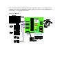
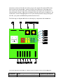
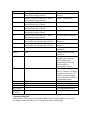
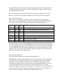
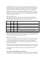
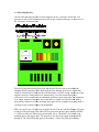
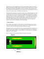
TWINSYNC
The Twin Engine Engine Syncronizer
USERS GUIDE and INSTRUCTION MANUAL
VERSION 2.4
For
Firmware Version 2.4
Hardware Version 2.4
October 12, 2009
By: Bill Wike
NOTE: REMOTE DISPLAY instructions in Section 7 page 19 of this manual
TWINSYNC QUICKSTART GUIDE
This document describes a quick step-by-step procedure of how to setup and install the
TwinSync.
1. Setup your airplane’s throttles mechanically so that the throttle servos operate as
they should with the transmitter end points with at least 100% in both directions
(idle and full throttle).
2. If you are using the TwinSync with engines that do not already have crank shaft
mounted magnets the you need to install magnets into the spinner back plates
(3/16”x1/16” magnets) or into the prop hub (1/8”x1/4” diametric magnets)
3. To install spinner mounted magnets, dill a 3/16” hole near the outside of each
spinner just deep enough so that the magnet are flush when installed. Glue one
magnet into each spinner using slow curing epoxy.
4. To install magnets into the prop hub for airplanes without spinners, drill a 1/8”
hole into the prop hub parallel to the crankshaft. Follow the directions in section
3.2 of the “Users Guide” for aligning the magnets before epoxying them in place.
5. To install the RPM sensors, connect a sensor to the TwinSync (NOTE THE
CORRECT ORIENTATION of the connector on the diagram below). Turn on
power and move the sensor by a magnet. Only one side of the sensor will detect
the magnet. When the orientation of magnet and sensor is correct one of the
Green LEDs will turn on. Mount both sensors about 1/16” to 1/8” from the
magnet so that the Green LEDs turn on once per prop rotation.
6. Now install the device into the airplane connecting everything as shown on the
diagram. The device can be wrapped with foam rubber or simply held to the
aircraft frame with tie wraps or double sided tape. The device is not sensitive to
vibration.
7. Turn on the transmitter and receiver with throttle channel from the receiver
connected to the Twinsync throttle input. Both yellow LEDs should be off at
either idle or full throttle. If one yellow LED stays on increase your end points
until both yellow LEDs are off at either idle or full throttle (this is temporary just
to get the direction correct). If the yellow LEDs go off at idle then your throttle
direction on your transmitter is correct. If the LEDs go off at full throttle then
reverse your throttle direction on the transmitter so that they go off at idle (we can
reverse the servos on the Twinsync so that this is not an issue).
8. At this point, both the yellow LEDs should go off at idle and one yellow LED
should come on as you advance the throttle. If you’re your throttle servos are
backwards the next step explains how to reverse them.
9. How to reverse the throttle servos: Turn the receiver and the Twinsync off. Move
the rotary switch to position “7”. Turn the receiver and Twinsync on. The LEDs
will flash several times indicating that you are in a programming mode. Now you
can press one button to reverse one servo and the other button reverses the other
servo. Just press the button for about a half of a second. A yellow LED will come
on when a servo is reversed and off when it is normal direction. After reversing
one or both servos move the rotary switch back to position “0” and turn power off
and back on. Check the servo direction and if not correct repeat this procedure.
10. The next step is to set the idle point. The Twinsync will never move the throttles
lower than this point while synchronizing engines or in the event of a dead this is
where it will move the running engine to. Set your transmitter throttle endpoints
the where they should be for your model (you should mechanically setup your
airplane so that throttle endpoints are at least 100% in both directions to get an
accurate sync). To set the idle point move the rotary switch to position “3” and
turn on the transmitter, receiver, and Twinsync. The LEDs will flash a few times.
After the LEDs stop flashing, move the transmitter stick to idle. Press each button
once to set the idle position for each engine. Move the rotary switch back to
position “0” and power off the TwinSync and receiver.
11. The next step is to set the full throttle point. This limits how far the Twinsync can
move the throttle. To set the full throttle point move the rotary switch to position
“5” and turn on the transmitter, receiver, and Twinsync. The LEDs will flash a
few times. After the LEDs stop flashing, move the transmitter stick to full throttle.
Press Button 1 (the button in the middle of the board closer to the rotary switch).
12. The final step is to set the synchronization turn on point. When the throttle is
above this point the Twinsync will synchronize the engines. Below this point the
Twinsync is disabled. To set the sync point move the rotary switch to position “5”
and turn on the transmitter, receiver, and Twinsync. The LEDs will flash a few
times. After the LEDs stop flashing, move the transmitter stick a couple of clicks
above idle. Press Button 2 (the button in the corner of the board). Move the rotary
switch back to position “0” and power off the TwinSync and receiver.
13. Move the rotary switch back to position “0” and power off the TwinSync and
receiver and turn them back on. Check that both yellow LEDs are off at idle and
one yellow led comes on just above idle.
You are now ready to fly with Synchronized engines. If you want to use the onboard
glow drivers or use the AUX Channel input for different operating modes please refer to
the Users Guide for connection details, programming and operational instructions. From
the factory if the AUX channel is connected it is assumed to be a two position switch and
will turn the glow plugs on and off. The glow plugs will not operate based on RPM in the
factory default mode.
To optimize and customize the operation of your TwinSync read or print out the complete
manual contained on the CD ROM or available for download at
www.troybuiltmodels.com or your local dealer.
Tech support is available in the Twin Forum on RCUniverse or email to
[email protected].
Note: All connections are oriented so that the ((-)) ground or black wire is toward the top
of the board, (+) Red is in the middle, and the signal wire (yellow, white, or Orange) are
toward the IC in the middle of the board:
Connection Diagram:
Synchronizer Introduction and Feature Set
This Twinsync allows twin engine airplanes to keep the engines running at the same
RPM and produce that unique sound when engines are synchronized in flight.
The TwinSync has a unique safety feature that brings the running engine immediately to
idle in the event that one engine stops with no change in throttle stick. This feature
prevents loss of control when one engine stops while flying the model. The pilot can
regain control of the idling engine by simply moving the throttle stick to idle. Control is
then returned to the throttle stick and the pilot has full control. This feature can be
disabled if desired.
The TwinSync has another safety feature to idle both engines if the loss of transmitter
signal is detected on a FM radio system. This feature operates similar to how PCM
transmitters and receivers operate. If a PCM radio is used with the TwinSync it will
operate as normal and the TwinSync has no impact on PCM failsafe operation.
The TwinSync has several additional modes of operation adding capabilities beyond just
keeping the engines synchronized. These modes will be described in detail later in this
manual.
The system has six universal radio connectors.
Engine 1 RPM sensor
Engine 2 RPM sensor
Engine 1 Throttle servo
Engine 2 Throttle servo
Throttle channel from Receiver
AUX channel from Receiver (optional)
There are two additional connections for optional onboard glow drivers.
There is also an additional connector for the optional RPM and status display.
There are six LEDs on the TwinSync that allow for easy installation, programming, and
feedback on the operational status.
WARNING: Running sensor wires by a Gasoline engine with a magneto ignition
(not an electronic ignition) and using rubber sparkplug caps will likely inject RFI
from the magneto and spark into the sensor wires resulting is poor sync or erratic
behavior. If used with gas engines only shielded metal sparkplug caps (like the
Bosch) should be used and care should be used in routing sensor wire away from
engine and magneto as far as possible.
1.0 System Operation and Theory
This system requires that each engine have a dedicated throttle servo.
The TwinSync monitors each engine’s RPM with a magnetic hall effect sensor. This is a
small device attached to the end of the supplied sensor wires. A magnet is supplied for
each engine. One magnet is mounted in each spinner (or optionally the prop hub for
planes without spinners) and the face of the sensor is mounted within a quarter of an inch
of the magnet. Please see the details to make sure the face of the sensors face the magnet
to properly detect rotation.
If you are using a gasoline engine with an electronic ignition, you can use the magnets
already mounted in the crank shaft for the RPM sensor and not mount new magnets in the
spinner.
You should only use the supplied hall effect sensors since there is additional circuitry in
the devices and other sensors may not be compatible with the voltages of the TwinSync.
The TwinSync reads the throttle signal from the receiver and this is the primary input
controlling all operations of the TwinSync. At less than the “sync point” (about 20% or
where ever it is programmed to be) on the throttle, the TwinSync passes the throttle
signal directly to the throttle servos. There are special operating modes that allow
functions below the throttle sync point but in the default mode the TwinSync does
nothing besides managing the glow plugs when the throttle stick is below the sync point.
When the throttle is above the sync point and if both engines have an RPM signal (i.e.
running), the TwinSync moves the servos to match the stick position then adjusts both
engine throttles to be synchronized. The slow engine is increased and the faster engine is
slowed to be synchronized. This process is continuous until the throttle stick is moved
again. When the stick is moved the process is repeated again. If the stick is brought to
less than the sync point of the throttle stick the device disengages and passed the receiver
signal directly to the servos again.
Without an RPM signal from both engines more than 1500 RPM, the TwinSync will not
manage the throttle servos to synchronize the engines. Without a RPM signal from both
engines the throttle signal is passed directly to the servos.
In the event an RPM signal is lost while the throttle is above the sync point and both
engines are running, both engines are immediately moved to idle. Control is returned to
the throttle stick by moving the stick to idle. This would be what would happen if a
magnet or sensor was lost during flight.
2.0 TwinSync Servo Adjustments
The device comes programmed ready to use without any additional programming for
100% endpoints on a Futaba 9C. Other radios will probably need to set the idle, full
throttle, and sync points. The user does have several programmable options available for
customizations. The TwinSync has the following servo parameters that the user can
change:
-
-
-
Servo center position (or servo offset): This is useful for fine tuning adjustments
rather than adjusting linkage.
Idle position: This is the position that the engines will be put in the event of a
dead stick or in independent run up mode.
Engine and servo response time: This allows the user to adjust the response time
of the device to work with brushless esc (the fastest), digital servos on gas
engines, digital servos on bug glow engine, to slow standard servos on high RPM
glow engines (the slowest response time). The device comes preset to what is
likely optimum position for glow and gas engines but if any “hunting” or
oscillation is observed it can be removed with this setting.
Full throttle position: Sync will not open the throttle past this position when in
synchronizing mode
Sync Point: This is the throttle stick position that the synchronizer engages rather
than just passing the throttle stick position to the servos like a “y” cable. Above
this it syncs the engines. Factory setting is about 20% throttle.
Servo reversing: This allows you to program each throttle servo to operate in
normal or reverse direction.
Servo reversing and center positions are always in use regardless if the device is
managing synchronization or not. This aids with setting up a twin engine airplane and
provides the additional safety of killing the engines with the loss of TX signal. The servos
are moved to idle if 1/4th of a second passes with no transmitter signal. Control is
returned once the transmitter signal is received again for 1/10th of a second. If the device
senses a loss in transmitter signal it moves the servos to low throttle.
Several other options are available by connecting a second auxiliary channel (AUX CH)
to the TwinSync. Programming and options available to use a second AUX CH are
described later in detail in this manual.
3.0 Connections and Installation
If you have a magnet installed on the crank of a gas engine, just flip over the sensor until
the LEDs turn on and mount that side of the sensor facing the crank.
If you want you can mount two magnets 180 degrees apart to balance the spinner.
However, they should face opposite directions so that the sensor only sees one magnet.
There is no advantage in using two magnets. The device has a limit of 23,000 RPM and
treats RPMs above 23,000 as zero RPM.
3.1 Installing Spinner Mounted Magnets
The first step in the installation is to determine the polarity of each magnet. The rpm
sensors are polarity sensitive so they only detect one side of a magnet. To check this plug
the sensors into the TwinSync along with the throttle channel and turn on the receiver.
Now, pass the sensors in front of both sides of the magnets. Green LED1 turns on when
the engine1 RPM sensor is in front of the correct side of the magnet. Green LED2 turns
on when engine2 RPM sensor is in front of the magnet. Mark the correct side of the
magnets with a magic marker so that the green LEDs are on when the marked side of the
magnets face the front side of the sensors (side that is beveled with writing – however
either side is fine to use).
For spinner mounting the magnets, drill a 3/16” hole in the outer part of the spinner back
just deep enough for the magnet to be flush with the back of the spinner. Glue the
magnets into the spinner using slow curing epoxy. You can balance the spinner by
drilling away some material near the magnet or installing a second magnet in the other
side facing the other direction so that the sensor only detects one magnet through a full
rotation. Extra magnets can be purchased through TwinSync dealers or any hardware or
store that sells “rare earth” magnets. At the time of writing this manual Radio Shack sells
very similar magnets that will work with the TwinSync.
To mount the sensors, locate a spot on the cowl or fuselage where the magnet will pass
within about 1/8” from the magnet. You may need to bend the sensor wires at 90 degrees
so the face of the sensor faces the magnet. Then epoxy the sensors to the fuselage or
cowling along with the wires immediately behind the sensors. Vibration will break the
sensor wires over time if not glued securely. Broken sensor wires due to vibration are not
covered under warranty. Do not face the top of the sensor toward the magnet – only the
face.
As an alternative if your engines do not have cowls, you can make a sensor mount from
5-ply aircraft plywood or four layer printed circuit board material that two of the engine
mounting crews go through and extends to right behind the spinners. Don not use
conductive material like metal for sensor mounts. See example diagrams below:
Magnets
Thick CA
Glue
Heat
Shrink
The magnet should not be in front of the sensor when the prop is rotated to the start of the
compression. In the event of a dead stick the dead engine prop will rotate to the start of
compression and this should not be where the magnet is in front of the sensor. Vibration
at this point can make the device think both engines are running and try to synchronize
them. The result of this symptom is in the event of a dead stick both engines are idled.
The control of the running engine is returned to the stick after bringing the stick to idle. If
the running engine is throttled up and then returns to idle again, vibration is causing the
unit to think both engines are running when one is stopped and the magnet or sensor
needs to be rotated.
3.2 Installing Prop Hub Mounted Magnets
re available direct
1/8” x ¼” diametric magnets (sides are magnetic rather than the ends) are
from Wike RC Products. These are to be used with glow motors without spinners. You
simply drill a 1/8” hole in the prop hub parallel to the crankshaft as shown in the picture
below.
The most important part of the installation is to get the magnet rotated correctly in the
hole before gluing it with JB Weld or slow curing epoxy. You want it oriented so that the
north and south pole align with the diameter of the prop hub. The way to determine the
correct rotation of the magnet is to ro
rotate
tate it under the sensor until the green sensor LED
comes on. Mark that spot on the magnet. Then continue rotating it in the same direction
until the green LED goes out and make a mark there. Now make a make in the middle of
the two marks made. This new ma
mark
rk in the middle is the position of magnet that should
face outward to the sensor. Before gluing it in, place it in the hole at the correct rotation
and make sure that the sensor detects it. Once you are comfortable permanently glue it
into the prop hub.
Mount the sensors in a similar manner as described for spinner mounted magnets. The
face of the sensor with this method should face the prop hub obviously.
3.3 Installing Everything Else
Now you are ready to connect everything including throttle servos, sensors, and throttle
channel from the receiver. Connect the Auxiliary channel if you are going to use an AUX
CH mode. The device comes preprogrammed to use the AUX CH input for turning the
glow plugs on and off. If you want to use AUX channel for a different function, please
refer to the AUX CH programming section.
MECHANICALLY SET UP YOUR AIRPLANE THROTTLE LINKAGES
MECHANICALLY TO USE AT LEAST 100% THROW OR ENDPOINTS IN BOTH
DIRECTIONS (IDLE AND FULL THROTTLE) BEFORE INSTALLING THE
TWINSYNC. The TwinSync needs precise servo control of throttles in order to
synchronize the engines. With endpoints set at 100% with a Futaba 9C no programming
of the device is required (depending on your brand and model of radio and unless you
have to change servo direction). If you want to reprogram the device to use the endpoints
you already have setup you can. However, the change in RPM per 1 degree of servo
movement dictates how accurate the device can synchronize the engines. For example if
1 degree of servo movement results in a 200 rpm change then the device may only be
able to synchronize the engines within 100-200 RPM rather than the typical 50 RPM
difference.
If your endpoints on low throttle are less than 100%, the TwinSync may not disengage at
idle unless you reprogram the Syncpoint. You can check this by turning on the
transmitter and receiver with throttle connected to the TwinSync. The Yellow LED4
should go off at idle and turn on just about idle and stay on through full throttle. If the
LED stays on at low throttle you either have your throttle direction backwards on the
transmitter or you need to increase your low throttle endpoint. This step also verifies that
your transmitter throttle is set to normal and not reverse direction. If the throttle channel
is reversed on the transmitter then LED4 will go off at full throttle. Set the transmitter
throttle direction so that the LED4 is off at idle. The Yellow LED4 is on when the
TwinSync will be managing throttles to synchronize the engines and off when the
transmitter stick is below 20% and is controlling the throttles.
It is better to adjust the mechanical linkage to get as close as possible before changing
any programming settings. If you do have a computer or programmable transmitter and
want to change end points, curves, etc. this device has the programmability to work with
your setup but if end points are set to less than 100% a loss in resolution will occur and
can result in throttle oscillation or less precise RPM control.
If you want to do some advanced programming and get the most accurate synced RPM
possible, then you should set your throttle end points at their maximum travel limits (120150% depending on the brand of radio you have). Then mechanically adjust the linkage
so that one limit kills the engine and the other has the carb at wide open. Then adjust your
transmitter so that one limit is reach when you give the engine kill command. The other
limit is achieved at full throttle. Continue to adjust your transmitter so that idle on the
stick result in the idle that you want (without turning on the engine kill mix/override or
with the throttle trim up). Then after everything works like you want it to WITHOUT the
synchronizer, install it and reprogram it to use your th
throttle position setup
up by storing the
new idle, sync point and full throttle positions into the device.
The following is a diagram of the device showing key components and connections:
The following table shows how to connect the device based on the previous diagram:
Component
J1
Color
White or yellow wire toward IC, Black
Connected to or Function
AUX channel from
LED1
toward bottom edge of board
White or yellow wire toward IC, Black
toward bottom edge of board
White or yellow wire toward IC, Black
toward bottom edge of board
White or yellow wire toward IC, Black
toward bottom edge of board
White or yellow wire toward IC, Black
toward bottom edge of board
White or yellow wire toward IC, Black
toward bottom edge of board
White or yellow wire toward IC, Black
toward bottom edge of board
White or yellow wire toward Left side of
board, Black toward right edge of board
White or yellow wire toward Left side of
board, Black toward right edge of board
RED
LED2
RED
LED3
Yellow
LED4
Yellow
LED5
LED6
BUTTON1
BUTTON2
SELECTOR
SWITCH
GREEN
GREEN
J2
J3
J4
J5
J6
J7
J8
J9
Receiver
Throttle channel from
Receiver
Engine1 Throttle Servo
Engine2 Throttle Servo
Engine1 RPM Sensor
Engine2 RPM Sensor
Optional Display connector
Optional Glowdriver
connector
Optional Glowdriver
connector
Flashes Status of J9 Glow
plug driver
Flashes Status of J9 Glow
plug driver
On when device is
managing sync and both
engines running (see
programming section for
function while in
programming modes)
On when Transmitter stick
above 1/5 throttle. Off when
transmitter stick below 1/5th
throttle. (see programming
section for function while in
programming modes)
RPM Sensor for Engine1
RPM Sensor for Engine2
See programming section
See programming section
See programming section
Connection Diagram
IMPORTANT: Note connector orientation White/Yellow/Orange signal wire is toward
the middle of the board. Black wire is always toward the outside edges.
NOTE POLARITY – REVERSING A PLUG CAN DAMAGE THE TWINSYNC AND
THE SENSORS. Connectors J1 through J6 all have the negative ((-)) lead to the pin
nearest the edge of the board. The center pins are all battery positive (+), the pins nearest
the large IC are the signal pins, either into the TwinSync or leading out from it. Your
You
warranty does not cover damage caused by improper connections.
All Futaba and JR connectors have the polarity correct with the negative wire black and
the positive wire red. So long as you put the black wire toward the edge of the board
you’re fine.
NOTE
TE PLEASE: Some Airtronics connectors had the negative wire in the center. If you
have one of these the wiring MUST be altered or the receiver, the servos, and the
TwinSync unit can be destroyed.
And, ALWAYS DO A RANGE CHECK BEFORE FLIGHT.
Refer to the onboard
nboard glow plug driver section for setup and operation of the glow plug
drivers.
4.0 RUN Mode and Programming
The selector switch should always be in position “0” as shown above to use the device.
When the device is powered up with the selector switch in any position other than “0” the
device is in a programming mode.
Never RUN the engines with the TwinSync with the selector switch in any position other
than “0” as a safety precaution.
To enter programming modes power the device up with the selector switch in any
position other than “0”. Both Yellow and the RED LEDs will flash ON and OFF for
about 3 seconds, to indicate that you are in a programming mode. After that they will still
flash at about a 1 second interval but with the programming modes displayed during the
regular flashing.
Changing the selector switch after the device is powered up will not enter programming
mode. But if the selector switch is moved to position “0” the device enters RUN mode
and power has to be cycled to re-enter programming mode.
Once in a programming mode, pressing BUTTON1 and BUTTON2 programs new values
into the device. The following section describes how to program each parameter for each
selector switch position:
Selector Switch Position 0:
This is run mode and to re-enter programming mode power has to be cycled with the
selector switch in any position other than “0”. BUTTON1 and BUTTON2 do nothing in
run mode.
Selector Switch Position 1:
This sets the engine1 servo center position. BUTTON1 increments the servo 1 step every
1/4th of a second it is held down. BUTTON2 decrements the servo 1 step every 1/4th of a
second it is held down. Mechanical adjustments should be adjusted as close as possible
and ideally the user does not need to use this function. Care should be used not to move
center to the point that a servo binds at the end points.
Selector Switch Position 2:
This sets the engine2 servo center position. BUTTON1 increments the servo 1 step every
1/4th of a second it is held down. BUTTON2 decrements the servo 1 step every 1/4th of a
second it is held down. Mechanical adjustments should be adjusted as close as possible
and ideally the user does not need to use this function. Care should be used not to move
center to the point that a servo binds at the end points.
Selector Switch Position 3:
This sets the preprogrammed idle position of BOTH Engines. The synchronizer moves
the servos to idle when a dead stick is detected. Dead stick condition is cleared by
moving the throttle stick to idle. This position is preprogrammed to be idle throttle stick
with full trim on most radios. This is also the idle position an engine is held in when in
the Independent Run-Up mode.
Move the throttle stick to the desired idle position and press each button one at a time.
Button 1 sets idle of the first engine and Button 2 sets the idle of the second engine.
Selector Switch Position 4:
This sets the device response time. Please email tech support before changing this
parameter. If you accidently change it. Please press the buttons until both yellow LEDs
are on and the red led is off. Then move the switch to a position other than 4.
LED1&2
RED
ON
ON
ON
ON
LED3
Yellow
ON
ON
OFF
OFF
LED4
Yellow
ON
OFF
ON
OFF
OFF
OFF
OFF
OFF
ON
ON
OFF
OFF
ON
OFF
ON
OFF
MODE
Fastest possible setting…
Very fast setting good for use with Brushless ESCs
Recommended setting for fast glow engines and servos
Setting for slow glow engines and std servos or very fast
Gas
Factory default mode for fast responding Gas engines
Slower
Slower than above setting
Slowest possible setting
The above table gives a basic understanding of the available control curves and response
time settings. In general a very fast responding engine and servos needs a fast setting and
a slow responding engine needs a slower response curve. If your response time setting is
too fast the RPM will oscillate and the engines will pass each other trying to sync. If the
response time is too slow the engine will take long to sync when you move the throttles
than they would with a faster response time.
Selector Switch Position 5:
This is the full throttle and Sync position programming mode.
Pressing Button 1 programs the Full Throttle Point. This is factory set for a Futaba 9C at
100% EPA. To set a new full throttle point, move the throttle stick to the desired full
throttle point and press Button 1 (closes to rotary switch). To program more or less
maximum servo throw, move the throttle stick to the maximum position the servos can
travel and press BUTTON1. The same value is stored for both servos. You must
mechanically adjust your linkage so full throttle on your transmitter results in full throttle
on both carbs. Think of this setting as just storing the end point in the synchronizer so
that it can advance an engine to full throttle without binding a servo.
Pressing Button 2 (closest to rotary switch) lets you program the point where the unit
starts to synchronize the engines. This is the point where the one yellow LED comes on
(or both if the engines are running. This should be set just above idle. To program this
point move the rotary switch to position 5 then turn power on. After the LEDs stop
flashing move your throttle stick to the desired synchronizer turn on point. Then Press
Button 2 (the one on the corner of the board). After that move the rotary switch back to
zero and verify that the yellow led comes on where you intended and stays on through
full throttle. It should be off at idle.
Selector Switch Position 6:
This is the mode where the use and function of an Auxiliary channel (AUX CH) is
defined. The LEDs display the mode the device is in when in this programming mode.
The following table allows the user to determine what mode you are in:
LED1&2
RED
ON
ON
LED3
Yellow
ON
ON
ON
ON
OFF
OFF
OFF
OFF
ON
ON
LED4 MODE
Yellow
ON
1. AUX CH not USED – Glow plugs based on RPM
OFF
2. Independent Run Up Mode – Glow plugs based on
RPM
ON
3. AUX CH turns sync on and off – Glow plugs via RPM
OFF
4. Rudder steering of throttles – Glow plugs based on
RPM
ON
5. AUX channel controls GLOW PLUGS (default)
OFF
6. No dead stick detection w/AUX controlling glow plugs
When in this programming mode hitting either BUTTON1 or BUTTON2 advances you
to the next mode. If you are in mode 5 and hit a button the device goes to mode 1. If you
are in mode 1 and hit a button the devices goes to mode 2.
Selector Switch Position 7:
This is the servo reversing programming mode. The LED3 reflects whether engine1 servo
is normal direction (LED3 off) or reverse direction (LED3 on). To change the engine1
servo direction push BUTTON1. Pressing BUTTON1 a second time reverses the
direction again. LED4 reflects the servo direction for engine2 and BUTTON2 changes
servo direction for engine2.
THE TRANSMITTER THROTTLE DIRECTION MUST BE SET SO THAT LED4 IS
OFF AT IDLE AND ON ABOVE THE SYNC POINT THROUGH FULL THROTTLE.
TWINSYNC WILL NOT OPERATE WITH THE TRANSMITTER THROTTLE
REVERSED.
How to Reset All Programming to Factory Defaults:
If you want to erase all programming in the device and return it to the factory defaults it
is possible. Move the rotary switch to position 7. Hold down both button 1 and button 2.
Power up the device. After the LEDs stop blinking the device is reprogrammed to all of
the factory defaults.
And, Always do a range check.
5.0 Auxiliary Channel Mode Functions and Details
The ability to connect an Auxiliary channel to the device is included and this section
explains the detail operation of how the device performs in each mode of AUX CH input
functions. The following sections explains each mode in detail:
MODE1: No AUX CH
This is the mode the device should be set to if an AUX CH is not connected to anything.
The device lets the throttle stick control servos below 1/5th stick. Above 1/5th stick the
devices moves the servos to that position and then synchronizes the engines. If the stick is
moved the process is repeated.
MODE2: Independent Run Up Mode
In this mode it is assumed that the AUX CH input is connected to a 3-position switch. If
the output of this channel is less than 1/3 deflection engine1 is controlled by the throttle
stick while engine2 is held at the programmed idle position. If the AUX CH output is
between 1/3 and 2/3rds full deflection then the throttle stick controls both engines and the
devices operates just like it was in mode 1. If the AUX CH output is greater than 2/3rds
deflection then the throttle stick controls engine2 and engine1 is held in the
preprogrammed idle position. This mode is useful for carb adjustments and mixture fine
tuning.
MODE3: AUX CH Sync Defeat
In this mode it is assumed that the aux channel input is connected to a channel with a 2position switch on the transmitter. In one position the synchronization function is
enabled. In the other position the device does nothing and is simply a “Y” cable (although
servo directions and center is still controlled by the device).
This is a useful mode for understanding how your plane will react while the engines are
being controlled by the device.
MODE4: AUX CH is for Rudder Steering
In this mode the device operates as in mode 1 (no AUX CH) above 1/3rd throttle. Below
1/3rd throttle the AUX CH is assumed to be connected to the RUDDER receiver output.
There is a dead band around the rudder center (so that rudder trim does not affect engine
RPM). When the rudder stick is moved far enough past center to get out of the dead band
it starts increasing the throttle on one engine. Moving the rudder stick in the other
direction will result in increasing the throttle on the other engine. Full rudder on the stick
at idle will result in about half throttle on the engine for that side.
This allows for taxiing airplanes with engine control rather than a steerable wheel.
This mode should also result in some interesting aerobatic maneuvers not possible with
single engine aircraft.
This mode is disabled if only one engine is running. It is operational if both engines or
neither engine is running. This allows for bench testing as well as operation only if both
engines are running.
Engines are not synchronized until the stick is above the rudder steer disengagement
point (33% throttle).
MODE5: AUX CH Controls Glow plugs on and off (FACTORY PRESET MODE)
In this mode the AUX CH turns the glow plug drivers on and off. A two position switch
should be used and in one position glow plugs will be off and in the other position the
glow plugs will be on.
MODE6: NO DEADSTICK DETECTION with AUX CH Controls Glow plugs
This mode is the same as MODE5 except that the engines are not idled in the event of a
deadstick. The engines are synchronized when the stick is above idle and both engines
are running. If both engines are not running then the throttle servos are just moved to the
transmitter stick position. This allows full throttle control of one running engine at all
times.
The reason for this mode is if you have a very stable twin engine plane that flies well on
one engine you may not want to idle the running engine in the event of a dead stick on
one engine.
Plugs are controlled by the AUX Channel just like in Mode 5.
In this mode the AUX CH turns the glow plug drivers on and off. A two position switch
should be used and in one position glow plugs will be off and in the other position the
glow plugs will be on.
6.0 Glow Plug Drivers
The on board glowplug drivers are now supported by the TwinSync version 2.0. The
glowdrivers are each a small board with a servo type connector that goes to J8 and J9 on
the TwinSync as shown below:
The wires going between the TwinSync and the glow drivers can be extended with
standard aileron extensions. The intent with the new onboard glow drivers is that they
could be mounted and in each nacelle with the battery to reduc
reducee wiring complexity of the
original TwinSync with glow drivers. Additionally, all of the needed wiring and
connectors is now included. So the additional purchase of glow plug clips and connectors
is no longer required. Each glow driver operates on a single cell nicad or nimh battery.
Each battery should be at least 1500maH. Each glow driver is capable of driving about 88
10 amps so twin cylinder engines can be handled.
There are two 18 awg red wires on each glow driver. The one with the alligator clip goes
to the tip of the glow plug. The other red wire goes to the positive glow battery terminal
(+). There are also two black wires on each glow driver. The black wire with the ring
terminal goes to the engine case. The intent is to put one of the engine mounting
mount
bolts
through it. The other black wire goes to the minus ((-)) side of the glow driver battery.
The glow drivers can be programmed to operate with an auxiliary channel or based on
RPM. If running based on RPM wiggle the propeller so that the magnet passes in front of
the RPM sensor and glow plug should come on for 10 seconds. Using an electric starter
on the engine will also automatically turn on the glow plugs. The glowplugs will come on
when ever the engine is below 3500 RPM in automatic mode.
There is an LED on the glow drivers that is on solid whenever the glow plugs are on. The
two RED leds on the TwinSync will turn on continuous when the glow drivers are on. If
the glow plug is not connected or burned out the RED led for that glow driver will flash
slowly. If a glow driver battery is getting low (below 1.15 volts under load) the RED led
for that glow driver on the TwinSync will flash rapidly. A glow driver battery can heat a
glow plug (depending on the plug) sometimes all the way down to 0.90 volts. So just
because the LEDs are flashing doesn’t mean that the battery is dead. An engine can
typically still be started even though the led started flashing.
7.0 Remote Display
The TwinSync remote display is to allow the user to mount the display where it can be
seen from outside the airplane when the plane is ready to fly. It can be mounted where
visible or it can been seen through many types of film type covering.
The display can now run on a single three wires connection (although two connectors are
included with the earlier displays – newer displays only include one wire). The Remote
display requires Battery Positive (+), Battery Minus (-), and the signal wire. The display
plugs into J7 on the TwinSync.
Below is a diagram of the back of the Display showing the connections:
Signal
Battery +
Battery -
8.0 Service, Parts, and Software Updates
During the warranty period software updates will be done at no cost other than a charge
for return mail of the complete unit. You will be expected to send the TwinSync unit
prepaid for this service. Enclose your check or money order for $5.00 to cover postage
and handling for the device to be returned to you.
If your installation is such that it is not easily removed from your airplane you can return
the ECU only for software updates.
For Service, Warranty and Software updates mail your device to:
Bill Wike
215 Preston Pines Drive
Cary, NC 27513
You contact tech support for support, repairs, and warranty via email to: [email protected]
On-line technical support is available at the following link:
http://www.rcuniverse.com/forum/m_4700596/tm.htm
This is the synchronizer support forum on RC Universe under the Twin and Multi-Engine
Forum or Airplanes.
9.0 Disclaimers, legalities, and warranty.
1) Manufacturer, distributor, and retail agents make no warranty, express or implied,
beyond the suitability of the TwinSync device as an engine control unit for synchronizing
two engines in a model airplane.
2) Warranty period is 90 days from the date of retail sale, plus five days if supported by a
mail order invoice. This warranty does not cover damage caused by improper connection
or operation. Also excluded from warranty coverage is wire breakage due to any cause.
3) In common with other electronic devices, the TwinSync can be destroyed by improper
connections. Any electrical damage deemed by the manufacturer or distributor to be due
to improper connection or installation will be repaired at owner’s expense.
4) By accepting the TwinSync unit you assume all responsibility for its use and
operation, and any damages that may be incurred while using it. You must be fully
familiar with its operation and limitations before flying your airplane with it installed. If
you do not accept this return the unused TwinSync unit for a full refund, excepting
mailing charges and costs.
5) Manufacturer’s and distributor’s liability is limited to the replacement cost of the
TwinSync unit.
This manual, the TwinSync name, design, software, and circuitry copyright 2006.
10.0 Specifications:
General TwinSync Specifications:
POWER Consumption:
Operating Voltage:
Servo Outputs:
Throttle input:
RPM Acuracy:
Syncronization accuracy:
15mA + 15mA per LED that is on
100ma Maximum
4.0-12.0 volts
5-2.5 us PWM, 40 fps (1.0-2.0us factory defaults)
0-3.3V output
25-80 fps 0.5-2.5 us PWM (1.0-2.0us factory
defaults)
0V to 2.0-5.0V peak-peak
100 rpm @23,000 and 10 rpm at 5,000
25-130 RPM depending on programming and servo
geometry
9.0 Updates in 2.0.0 Version of Software from Version 1.4.5
1) Nothing added except for support of new 2.0 hardware.