1
-
-
-
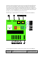
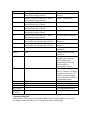
Servo center position (or servo offset): This is useful for fine tuning adjustments
rather than adjusting linkage.
Idle position: This is the position that the engines will be put in the event of a
dead stick or in independent run up mode.
Engine and servo response time: This allows the user to adjust the response time
of the device to work with brushless esc (the fastest), digital servos on gas
engines, digital servos on bug glow engine, to slow standard servos on high RPM
glow engines (the slowest response time). The device comes preset to what is
likely optimum position for glow and gas engines but if any “hunting” or
oscillation is observed it can be removed with this setting.
Full throttle position: Sync will not open the throttle past this position when in
synchronizing mode
Sync Point: This is the throttle stick position that the synchronizer engages rather
than just passing the throttle stick position to the servos like a “y” cable. Above
this it syncs the engines. Factory setting is about 20% throttle.
Servo reversing: This allows you to program each throttle servo to operate in
normal or reverse direction.
Servo reversing and center positions are always in use regardless if the device is
managing synchronization or not. This aids with setting up a twin engine airplane and
provides the additional safety of killing the engines with the loss of TX signal. The servos
are moved to idle if 1/4th of a second passes with no transmitter signal. Control is
returned once the transmitter signal is received again for 1/10th of a second. If the device
senses a loss in transmitter signal it moves the servos to low throttle.
Several other options are available by connecting a second auxiliary channel (AUX CH)
to the TwinSync. Programming and options available to use a second AUX CH are
described later in detail in this manual.
3.0 Connections and Installation
If you have a magnet installed on the crank of a gas engine, just flip over the sensor until
the LEDs turn on and mount that side of the sensor facing the crank.
If you want you can mount two magnets 180 degrees apart to balance the spinner.
However, they should face opposite directions so that the sensor only sees one magnet.
There is no advantage in using two magnets. The device has a limit of 23,000 RPM and
treats RPMs above 23,000 as zero RPM.
3.1 Installing Spinner Mounted Magnets
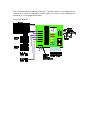
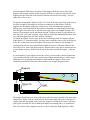
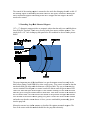
The first step in the installation is to determine the polarity of each magnet. The rpm
sensors are polarity sensitive so they only detect one side of a magnet. To check this plug
the sensors into the TwinSync along with the throttle channel and turn on the receiver.
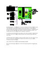
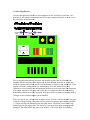
Now, pass the sensors in front of both sides of the magnets. Green LED1 turns on when
the engine1 RPM sensor is in front of the correct side of the magnet. Green LED2 turns