1
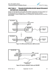
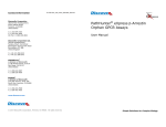
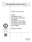
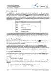
VM-Series Multiplexer
User Manual
20/02/2002 12:00
Videoswitch
______________________________
VM-Series Multiplexer
User Manual
Products covered by this manual:
Monochrome
Simplex
Mini Duplex Plus
Duplex Plus
Telemetry Duplex Plus
4 Cameras
VM-401M
VM-402M
VM-403M
VM-404M
8 Cameras
VM-801M
VM-802M
VM-803M
VM-804M
12 Cameras
VM-1201M
16 Cameras
VM-1601M
20 Cameras
VM-2001M
VM-1203M
VM-1204M
VM-1603M
VM-1604M
VM-2003M
VM-2004M
Colour
Simplex
Mini Duplex Plus
Duplex Plus
Telemetry Duplex Plus
4 Cameras
VM-401C
VM-402C
VM-403C
VM-404C
8 Cameras
VM-801C
VM-802C
VM-803C
VM-804C
12 Cameras
VM-1201C
16 Cameras
VM-1601C
20 Cameras
VM-2001C
VM-1203C
VM-1204C
VM-1603C
VM-1604C
VM-2003C
VM-2004C
Videoswitch
Units 15 & 16
Redfields Industrial Park
Redfields lane
Church Crookham
Hants GU52 0RD
England
Videoswitch
Telephone
Fax
Email
Web
1
01252-851510
01252-851296
[email protected]
www.videoswitch.co.uk
VM601h.doc
VM-Series Multiplexer
User Manual
20/02/2002 12:00
Contents:
1.
Getting Started ............................................................................................................................................................................3
Overview..................................................................................................................................................................................3
Connecting Up .........................................................................................................................................................................3
Interconnection Diagram ..........................................................................................................................................................4
Basic Operation...........................................................................................................................................................................5
2.1
Live Viewing.............................................................................................................................................................................5
2.2
Recording ................................................................................................................................................................................5
2.3
Playback ..................................................................................................................................................................................5
The Front Panel Keys ..................................................................................................................................................................6
3.1
Front Panel Diagram ................................................................................................................................................................7
3.2
Primary Functions ....................................................................................................................................................................8
3.2.1
Monitors A, B.................................................................................................................................................................8
3.2.2
PLAY.............................................................................................................................................................................8
3.2.3
Cameras 1,2,3,4 etc. .....................................................................................................................................................8
3.2.4
Picture-in-Picture...........................................................................................................................................................8
3.2.5
Quad .............................................................................................................................................................................8
3.2.6
Multi-Screens ................................................................................................................................................................8
3.2.7
Focus (Telemetry models only) .....................................................................................................................................8
3.2.8
Zoom and Focus (Telemetry models only) ....................................................................................................................8
3.2.9
Joystick (Telemetry models only) ..................................................................................................................................9
3.3
BLUE Functions .......................................................................................................................................................................9
3.3.1
Enter Menu....................................................................................................................................................................9
3.3.2
Auto...............................................................................................................................................................................9
3.3.3
Alarm.............................................................................................................................................................................9
3.3.4
Freeze ...........................................................................................................................................................................9
3.3.5
Digital Zoom ..................................................................................................................................................................9
3.3.6
Iris (Telemetry models only) ..........................................................................................................................................9
3.3.7
Presets (Telemetry models only) ...................................................................................................................................9
3.3.8
Auxiliaries (Telemetry models only) ...............................................................................................................................9
3.3.9
Telemetry controls which Camera? ...............................................................................................................................9
3.4
MENU Functions....................................................................................................................................................................10
3.4.1
Back ............................................................................................................................................................................10
3.4.2
Select ..........................................................................................................................................................................10
3.4.3
Default.........................................................................................................................................................................10
3.4.4
Up ...............................................................................................................................................................................10
3.4.5
Down ...........................................................................................................................................................................10
3.4.6
Left ..............................................................................................................................................................................11
3.4.7
Right............................................................................................................................................................................11
Status Information.....................................................................................................................................................................12
4.1
Time, Date and Day of Week .................................................................................................................................................12
4.2
Titles ......................................................................................................................................................................................12
4.2.1
Multiplexer Title ...........................................................................................................................................................12
4.2.2
Cameras Titles ............................................................................................................................................................12
4.3
Status Information..................................................................................................................................................................12
4.3.1
Time Windows.............................................................................................................................................................12
4.3.2
Alarms.........................................................................................................................................................................12
4.3.3
Sequencing .................................................................................................................................................................12
4.3.4
Time-Lapse Mode .......................................................................................................................................................12
The Menus .................................................................................................................................................................................13
5.1
Passwords .............................................................................................................................................................................13
5.2
User Menu .............................................................................................................................................................................13
5.3
Installer Menu ........................................................................................................................................................................15
5.4
Manager Menu.......................................................................................................................................................................19
Specifications............................................................................................................................................................................20
6.1
Frame Stores .........................................................................................................................................................................20
6.1.1
Multiplexing Update Rate (PAL)...................................................................................................................................20
6.1.2
Resolution (PAL) .........................................................................................................................................................20
6.2
Inputs/Outputs .......................................................................................................................................................................20
6.2.1
Video...........................................................................................................................................................................20
6.2.2
VCR Sync....................................................................................................................................................................20
6.2.3
Dome ..........................................................................................................................................................................20
6.2.4
Twisted Pair Telemetry................................................................................................................................................20
6.2.5
Co-Ax Telemetry .........................................................................................................................................................20
6.2.6
Remote Control ...........................................................................................................................................................20
6.2.7
Alarm Inputs ................................................................................................................................................................20
6.2.8
Alarm Relay Contacts..................................................................................................................................................20
6.3
Connector Pin-Outs ...............................................................................................................................................................20
6.3.1
Alarm Connector .........................................................................................................................................................20
6.3.2
Remote Connector ......................................................................................................................................................21
6.4
Power ....................................................................................................................................................................................21
6.4.1
DC Power....................................................................................................................................................................21
6.4.2
AC Power (via main adapter provided) ........................................................................................................................21
6.5
Physical and Environmental...................................................................................................................................................21
6.5.1
Unit Dimensions ..........................................................................................................................................................21
6.5.2
Packaged Dimensions.................................................................................................................................................21
6.5.3
Weights .......................................................................................................................................................................21
6.5.4
Operating Temperature ...............................................................................................................................................21
6.5.5
Storage Temperature ..................................................................................................................................................21
6.5.6
Humidity ......................................................................................................................................................................21
6.5.7
Ventilation ...................................................................................................................................................................21
1.1
1.2
1.3
2.
3.
4.
5.
6.
Videoswitch
2
VM601h.doc
VM-Series Multiplexer
User Manual
20/02/2002 12:00
1. Getting Started
1.1 Overview
Congratulations on choosing a Videoswitch multiplexer. This product combines ease-of-use with high image
quality and reliability. Basic day-to-day operation is performed by one-press operation of the front panel keys.
Configuration of the multiplexer is accomplished by entering the easy-to-use password protected menus.
1.2 Connecting Up
This table indicates what each connector on rear panel of the multiplexer should be connected to. Note that
in all installations some connections are essential. Others are optional, depending on whether you require
special facilities such alarms, automatic time lapse mode switching and remote control.
Connector
identification on
Rear Panel of
Multiplexer
CAMERA “1”
CAMERA“2”
CAMERA“3”
CAMERA“4”
…etc
MONITOR “A”
MONITOR “B”
VCR “PLAY”
VCR “RECORD”
“12V DC 2A”
“VCR SYNC”
“ALARMS”
“ALARMS”
“REMOTE”
“e-BUS”
Videoswitch
What to connect it to…
Connecting cable
required
Essential in most
systems?
a Colour or Monochrome Camera
a Colour or Monochrome Camera
a Colour or Monochrome Camera
a Colour or Monochrome Camera
…etc
Monitor (main control monitor)
Monitor (public display monitor or
secondary control monitor)
Connect to VCR’s video Output
Connect to VCR’s video Input
Connect to Videoswitch 12V dc, 2Amp
power supply (PSU)
Connect to VCR’s “Camera Switch” or
“Sync” terminal
BNC to BNC
BNC to BNC
BNC to BNC
BNC to BNC
…etc
BNC to BNC
BNC to BNC
Yes
Yes
Optional
Optional
Optional
Yes
Optional
BNC to BNC
BNC to BNC
Attached to PSU
(provided)
Phono to single wire
(provided)
Yes
Yes
Yes
Connect inputs to PIR detectors or other
devices with volt-free contacts.
Connect alarm relay output contacts to
VCR’s time-lapse mode control input
VK-3201 or VK-3202 Remote keyboard,
or to Computer
25-way D-type Male
to twisted pairs
25-way D-type Male
to 3 single wires
Male 9-way D-type to
Female 9-way D-type
Do not connect to anything! This is used
for factory software upgrades.
none
3
Preferred, so that
time-lapse
configuration is
automatic.
Optional
Optional
If remote
keyboard is
required
No
VM601h.doc
Videoswitch
1
2
4
5
6
7
8
9
4
10
VCR
11
12
13
14
15
REC
VCR
PLAY REC
PLAY
S-VIDEO
OUT
S-VIDEO RECORD/PLAY
OPTION
16-CAMERA MULTIPLEXER REAR VIEW
(other models similar)
25
ALARMS
IN
CAMERA
SWITCH
REMOTE
KEYBOARD
OR
COMPUTER
B
MONITOR
A
13
1
240VAC
MAINS
MAINS
POWER
SUPPLY
12V DC 2A
14
DO NOT
CONNECT
ANYTHING
TO THIS
PORT
User Manual
CAMERAS
(8 shown asexample)
3
CAMERA LOOP-THROUGH OUTPUTS
ALARM CONTACTS
(2 shown as example)
VM-Series Multiplexer
20/02/2002 12:00
1.3 Interconnection Diagram
VM601h.doc
VM-Series Multiplexer
User Manual
20/02/2002 12:00
2. Basic Operation
2.1 Live Viewing
One or both monitors may be used for live viewing, with various combinations of full screen images and
multi-screen images displayed on the two monitors (Simplex models always display full screen images in live
mode).
• Select which monitor you wish to view by pressing “MONITOR A” or “MONITOR B” keys (not applicable to
Simplex models).
• Press the camera keys identified as “1”, “2”, “3”, “4” etc. to select a full screen image of a camera on the
selected monitor.
• Press the “PIP”, “QUAD” or “MULT-SCREEN” keys to see multiple cameras images on the selected
monitor (not applicable to Simplex models)
2.2 Recording
When the VCR and multiplexer are both in “RECORD” mode, images from all the cameras will be
continuously recorded onto tape. Irrespective of what is being displayed on the monitors, the system will
always record full screen images onto tape, providing maximum recorded image quality. This is the primary
purpose of a video multiplexer.
• The multiplexer is normally in RECORD. If the word “PLAY” is displayed on monitor “A”, press the “PLAY”
key momentarily to return to RECORD mode. The VCR is put in record mode by pressing its “REC”
button (refer to VCR’s manual for details).
• The time lapse mode of the VCR must be set. Typically the 24 hour mode or 27 hour mode is selected
which means that a 180 minute VHS tape will last for a whole 24 hour period (refer to VCR’s manual for
details).
• If a “VCR Sync” cable is used , the time lapse mode of the multiplexer is set automatically . Otherwise the
time lapse mode of the multiplexer must be set to match that of the VCR (via the Installer menu).
2.3 Playback
Both the VCR and the multiplexer must be in “PLAY” mode in order to play back recordings.
• To put the multiplexer into PLAY mode, press its PLAY key and keep it pressed for about one second
until the word “PLAY” appears on Monitor “A”.
• To put the VCR into play mode press its “PLAY” key (refer to VCR’s manual for details).
• Playback is always on monitor “A” and may optionally be on monitor “B” also (refer to configuration
section)
• When the system is playing back recorded images, the full screen image from any of the cameras may be
selected.
• If you wish to see more than one camera image at a time, press the “PIP”, “QUAD” or “MULT-SCREEN”
keys as required.
• Remember to routinely play back tapes to verify the correct functioning of the whole system.
Videoswitch
5
VM601h.doc
VM-Series Multiplexer
User Manual
20/02/2002 12:00
3. The Front Panel Keys
• The primary functions of the front panel keys allow the various display and record/play modes of the
multiplexer to be selected.
• Some keys have secondary “Blue Functions”. These additional facilities are accessed either by pressing
and holding the BLUE key and then pressing another key, or by momentarily pressing the BLUE key, and
then pressing another key within 2 seconds.
• When the menus are entered (BLUE + MONITOR “A”), some of the keys then assume menu control
functions, i.e. SELECT, BACK, ï ð ñ ò and DEFAULT (PLAY key)
Videoswitch
6
VM601h.doc
Videoswitch
7
MONITOR
BLUE
FUNCTIONS
MENU
A
PLAY
hold for
1 second
CAMERA
2
3
ï
4
5
7
8
1
CAMERA
2
4
ð
3
ï
5
6
7
8
VM-800 Series Multiplexer
ALARM
FREEZE
ZOOM
Videoswitch
9
10
11
12
13
14
15
16
17
20
ALARM
FREEZE
ZOOM
VM-2000 Series Multiplexer
Videoswitch
User Manual
AUTO
SELECT
B
PLAY
hold for
1 second
VM-2000 Series MULTIPLEXER FRONT PANEL
(other 19” models are similar)
AUTO
MENU
B
SELECT
A
BLUE
FUNCTIONS BACK
MONITOR
VM-800 Series MULTIPLEXER FRONT PANEL
(other compact models are similar)
VM-Series Multiplexer
20/02/2002 12:00
3.1 Front Panel Diagram
VM601h.doc
VM-Series Multiplexer
User Manual
20/02/2002 12:00
3.2 Primary Functions
3.2.1 Monitors A, B
Press the Monitor “A” key to select that monitor. The “Camera”, “Picture-in-Picture”, “Quad” and “MultiScreen” keys may be then pressed to call up an image on monitor “A”.
If you now press Monitor “B”, the same “Camera”, “Picture-in-Picture”, “Quad” and “Multi-Screen” keys may
be then be used to call up a different image on monitor “B”.
Note that although the two monitors can display different image formats, not all combinations are possible. If
an image is selected on one monitor that cannot be displayed simultaneously with the image being displayed
on the other monitor, the other monitor will revert to full screen display (refer to user menu for mode locking).
For example, it is not possible to display two different full screen images (in RECORD mode), whereas is is
possible to display two different quads, a Quad and a PIP or a full screen image and any different type of
screen image.
3.2.2 PLAY
This key is used to switch between RECORD and PLAY modes. This key must be pressed and held for
about one second in order to select PLAY mode. This feature is to prevent accidental interruption to the
normal recording process. Selection of PLAY mode may be prohibited by means of a Manager Menu option
for added safety.
3.2.3 Cameras 1,2,3,4 etc.
The camera keys are used to select a full screen image of any of the cameras on the currently selected
monitor.
3.2.4 Picture-in-Picture
This key selects Picture-in-Picture (PIP) mode in which a small image of one of the cameras is displayed in a
corner of the screen, whilst the rest of the screen display the image from another camera. Before selecting
PIP, select the full screen image of the camera that you want in the PIP. After selecting PIP mode, us the
Camera 1,2,3,4 etc keys to change the main image. Press the PIP key again to revert to normal full screen
mode.
3.2.5 Quad
Press the QUAD key to display cameras 1, 2, 3 and 4 on the currently selected monitor. For multiplexers with
more than four camera inputs, this key may be pressed again to display different groups of four cameras.
Note that a different quad may be displayed on each monitor.
3.2.6 Multi-Screens
Multiplexers with more than four cameras are provide with one or more MULTI-SCREEN keys. The various
models can display multi-screen images as follows. Press the MULTI-SCREEN keys again to select different
options:
Models
4 Cameras
8 Cameras
12 Cameras
16 Cameras
20 Cameras
Quad
ü
ü
ü
ü
ü
x8
x9
ü
ü
ü
x12
x16
x20
ü
ü
ü
ü
ü
3.2.7 Focus (Telemetry models only)
Multiplexers with telemetry and dome support have keys to control the Focus of a camera that is either within
a dome or is controlled by a Videoswitch telemetry receiver. To revert to auto-focus, press the camera select
key again (1,2,3 etc).
3.2.8 Zoom and Focus (Telemetry models only)
Multiplexers with telemetry and dome support have keys to control the Zoom and Focus of a camera that is
either within a dome or is controlled by a Videoswitch telemetry receiver
Videoswitch
8
VM601h.doc
VM-Series Multiplexer
User Manual
20/02/2002 12:00
3.2.9 Joystick (Telemetry models only)
Multiplexers with telemetry and dome support have a joystick. This is used to move a camera either in a
dome, or on a pan and tilt head controlled by a Videoswitch receiver. Note that the camera that is controlled
is the one last selected for display as a full screen analogue image.
3.3 BLUE Functions
3.3.1 Enter Menu
To enter the menu system, press the BLUE key and the Monitor “A” key. See section 3.3.10 for the “MENU
keys” that become available once you have entered the menu system.
3.3.2 VCR Direct View
Press the BLUE key and the PLAY key to enter VCR Direct view mode (not available if coverts are enabled).
The output of the VCR will be displayed. This mode is useful for setting up the VCR menu and, during
installation, for checking VCR connections. If the VCR is in LIVE mode, rapidly multiplexing images should
be seen. If the VCR is in PLAY mode, then whatever is being played back from the tape will be displayed.
3.3.3 Auto
Press the BLUE key and the Monitor “B” key. The word “SEQ” will appear on the currently selected monitor.
If a full screen image is being displayed, then full screen images will sequence. If a quad image is being
displayed when you enter Auto Sequence mode, then different available quads will sequence. The cameras
that are included, the dwell time and the mode (random or sequential) may be modified from within the
menus. To cancel sequencing, press BLUE and Monitor “B” again.
3.3.4 Alarm
Press the BLUE key and the PIP key to lockout alarms, indicated by a key symbol on Monitor “A”. Alarm
lockout is a convenience feature that prevents alarms from changing screen modes while you are manual
controlling the multiplexer.
3.3.5 Freeze
Press the BLUE key and the QUAD key to digitally freeze the image (RECORD or PLAY mode).
3.3.6 Digital Zoom
Press the BLUE key and the MULTI-SCREEN key to digitally enlarge an image. Camera keys “1”, “2”, “3”
and “4” (also identified by as ï ð ñ ò) may then be used to select different parts of the enlarged
image.
3.3.7 Iris (Telemetry models only)
Press the BLUE key and move the joystick up or down to control the iris (if applicable). To revert to auto-iris,
press the camera select key again (1,2,3 etc).
3.3.8 Presets (Telemetry models only)
Press the BLUE key and on of the Cameras keys “1”, “2”, “3” etc to call up a preset position on a dome
camera or pan and tilt head. A User menu option specifies whether a single preset or a group of presets (for
a preset tour) may be selected.
3.3.9 Auxiliaries (Telemetry models only)
Press the BLUE key and one of the FOCUS or ZOOM keys to operate auxiliary relays on a telemetry
receiver. The following auxiliary functions are available:
Auxiliary
1
2
3
4
5
Type
Latched
Latched
Latched
Momentary
Latched
Normal Use
Lamp
Receiver Alarm Enable
Wipe
Wash
Auto-Pan / Tour
Key
FOCUS (left)
FOCUS (right)
ZOOM (left)
ZOOM (left) - press and hold
ZOOM (right)
3.3.10 Telemetry controls which Camera?
Telemetry functions operate on the camera that is currently being displayed as a full screen analogue image.
It is suggested that the display mode for monitor A is analogue when telemetry is used. Refer to User menu.
Telemetry is not available in PLAY mode.
Videoswitch
9
VM601h.doc
VM-Series Multiplexer
User Manual
20/02/2002 12:00
3.4 MENU Functions
Once you have entered the menu system (BLUE key + Monitor “A” key), the following keys are the only ones
that are used to navigate within the menus and to select the various configuration options. Note that the
bottom line of text on the menu screen indicates which keys can be used. Menus are displayed on monitor
“A” only.
The most important menu keys are ñ ò, SELECT and BACK.
3.4.1 Back
This key (also identified as the Monitor “A” key) is used to come back a step from wherever you are in the
menu system.
• When have selected the option you require in a particular part of the menu system, press the BACK key
to return to where you were.
• If you are right at the start of the menu, pressing the BACK key will cause you exit the menu system
altogether.
3.4.2 Select
The key (also identified as the Monitor “B” key) is used to:
• select a sub-menu and takes you deeper into the menu system. If you have pressed SELECT to look at a
sub-menu or change a setting, you may press BACK to return
• move on to the next character or digit when setting time, date, numeric values or text
3.4.3 Default
This key (identified as the “PLAY” key) must be pressed and held for a second in order to act.
It is a very convenient way to set individual menu options to their default value and to turn groups of settings
on or off For example, depending where you are in the menu system, it is used to:
• Go to top of a menu
• Select the default option in a list
• Select a default numeric value (e.g. set a dwell time to 1)
• Clear a camera Title
• Tall all the activity zones on or off
• Where a line of dashes and blocks are displayed (e.g. cameras to be auto sequenced), this key will set
them all on or off in one key press..
Where ever you are in the menu, if you do not know what something should be set to, press this DEFAULT
key.
3.4.4 Up
The ñ key (also identified as the Cameras “1” key) has a number of function depending on where you are
in the menu:
• Move up through a list of menu items to select the one you require
• Increment a numeric value (such as a dwell time, password, time or date)
• Move up to select individual motion detect zones
• Increment motion detection sensitivity
• Move the position of the date/time or a title upwards
3.4.5 Down
The ò key (also identified as the Cameras “2” key) has a number of function depending on where you are in
the menu:
• Move down through a list of menu items to select the one you require
• Decrement a numeric value (such as a dwell time, password, time or date)
• Move down to select individual motion detect zones
• Increment motion detection sensitivity
Videoswitch
10
VM601h.doc
VM-Series Multiplexer
User Manual
20/02/2002 12:00
• Move the position of the date/time or a title downwards
3.4.6 Left
The ï
key (also identified as the Cameras “3” key) is used to:
• Move to a different digit when setting a multiple digit number, time or date
• Select which dash or block you want to modify (e.g. cameras to be auto sequenced),
• Select which character you wish to modify when editing a camera title
• Move the position of the date/time or a title to the left
3.4.7 Right
The ð
key (also identified as the Cameras “4” key) is used to:
• Move to a different digit when setting a multiple digit number, time or date
• Select which dash or block you want to modify (e.g. cameras to be auto sequenced),
• Select which character you wish to modify when editing a camera title
• Move the position of the date/time or a title to the right
Videoswitch
11
VM601h.doc
VM-Series Multiplexer
User Manual
20/02/2002 12:00
4. Status Information
The monitor display information that helps you use the multiplexer. Some of this information may be turned
off in the menus.
4.1 Time, Date and Day of Week
If the internal clock is to be used for time-stamping of recorded images, the time and date is also displayed
on Monitor “A”. Remember to disable the time and date display on the VCR otherwise you may have two sets
of information recorded onto tape.
4.2 Titles
4.2.1 Multiplexer Title
A sixteen character title may be enter via the Installer menu to identify the multiplexer. This title may be
recorded onto tape if required.
4.2.2 Cameras Titles
Each camera may have a sixteen character title associated with it that is displayed on the screen. These title
are not stored onto tape, but will be displayed when the tape is replayed.
If titles are too long to be displayed in certain multi-screen modes, they will automatically be replaced on the
screen with the cameras number.
4.3 Status Information
The following status information may be displayed (only on monitor “A” unless otherwise stated):
4.3.1 Time Windows
A clock symbol is displayed if the current time and day of week does not lie within a time window. This is
relevant if activity detection or alarm inputs have be set-up to operate within time windows. In this case, it
means that the multiplexer will not respond to alarms when the clock symbol is being displayed.
4.3.2 Alarms
If an activity detection or an alarm contact alarm is occurring, the text “ALM” will appear on the screen.
If you have locked out the alarms, a key symbol followed by “AL” will be displayed. This indicates that the
multiplexer will not currently respond to any alarms.
4.3.3 Sequencing
The word “SEQ” will appear if auto sequencing is currently in process. This can appear on both monitors.
4.3.4 Time-Lapse Mode
In RECORD mode, the time lapse mode that the multiplexer is operating in is displayed (e.g. 24 hr). If the
multiplexing is automatically detecting the time lapse mode from the “VCR Sync” signal, it will display an
arrow in a diamond symbol in front of the time lapse mode. This confirms that the sync pulse is being
detected properly.
Videoswitch
12
VM601h.doc
VM-Series Multiplexer
User Manual
20/02/2002 12:00
5. The Menus
This multiplexer is provided with a comprehensive but easy to use menu system. The menus are divided in
three different sections, each of which may be password protected:
• User Menu
-
this deals with mainly with display options
• Installer
-
most of the detailed configuration is performed in this menu
• Manager
-
this menu provides protected access to covert cameras
5.1 Passwords
Up to three different passwords may be set (each is a six digit number). A password that is set to “000000”
allows free access.
The first password to set is the Manager password, and this is set in Manager menu. This password will
allow access to all three menus. Set this password to zero if you want no password protection at all.
If you want separate password protection for the installer menu, a second password may be set in the
installer menu. This password will allow access to the installer and user menus.
If you want a third password for the user menu, a password may be set in the user menu. This password will
allow access to the installer menu only.
When a menu is locked by a password, a key symbol is displayed adjacent to the menu name when you first
enter the menu system. If you press SELECT to enter a password protected menu, you will need to enter a
password. When you have entered a password, you will be granted access to the permitted menus. If you
exit the menu system altogether but then re-enter them within 30 seconds, you do not have to key in the
password again.
5.2 User Menu
The options appearing in this menu are shown in this table. Note that some options are not applicable to all
multiplexer models. Press and hold the PLAY key to set any option to its default state.
Sub-Menus & Options
Set Time HH:MM:SS
Press SELECT to enter option, then do the following:
Set the date using ï ð ñ ò. Press BACK to
finish.
Set the time using ï ð ñ ò. Press BACK to
finish.
Set Date DD/MM/YY
Full Screen Display Mode
Monitor A
The full screen may be either Analogue for best
resolution and refresh speed, or digital for zero bounce
on switching. Use ñ ò. Press BACK to finish.
The full screen may be either Analogue for best
resolution and refresh speed, or digital for zero bounce
on switching. Use ñ ò. Press BACK to finish.
This option allows display modes to be locked such
that selection of a conflicting mode on the other
monitor is prevented. Use ñ ò. Press BACK to
finish.
Set anti-flicker mode if shimmering effects are
obtrusive on the multi-screen images. Use ñ ò.
Press BACK to finish.
Monitor B
Display Mode Locking
Multi-Screen Anti-Flicker
Picture in Picture
PIP Position
Set the PIP position using ñ ò. Press BACK to
finish.
Use ñ ò keys to select whether Camera 1,2, 3 etc
keys affect the main image or the PIP image. Also
affects which one auto sequences. Press BACK to
finish.
PIP Selection/Sequencing
Monitor A Auto Sequencing
Camera List
Select which cameras are to be included in the
sequencing using ñ ò and SELECT. Press BACK to
finish.
Full screen sequencing may be set to random mode
Random Sequencing
Videoswitch
13
VM601h.doc
VM-Series Multiplexer
User Manual
20/02/2002 12:00
here using ñ ò. Press BACK to finish.
Full Screen Dwell Times
Camera 1,2,3 etc
Full-Screen Dwell Time
Multi-Screen Dwell Time
Monitor B Auto Sequencing
Camera List
Select which cameras are to be included in the
sequencing using ñ ò and SELECT. Press BACK to
finish.
Full screen sequencing may be set to random mode
here using ñ ò. Press BACK to finish.
Random Sequencing
Full Screen Dwell Times
Camera 1,2,3 etc
Full-Screen Dwell Time
Multi-Screen Dwell Time
Change User Password
Videoswitch
Set the required camera using ñ ò, then press
ENTER to continue or BACK to finish.
Set the dwell time using ñ ò. Press BACK to finish.
For multiplexer with more than 4 cameras, Quads may
be sequenced. With 16 camera multiplexers, the 8way multi-screens may be sequenced. Set the dwell
time using ñ ò. Press BACK to finish.
14
Select the required camera using ñ ò, then press
ENTER to continue or BACK to finish.
Set the dwell time using ñ ò. Press BACK to finish.
For multiplexer with more than 4 cameras, Quads may
be sequenced. With 16 camera multiplexers, the 8way multi-screens may be sequenced. Set the dwell
time using ñ ò. Press BACK to finish.
The user password may be set here. Set to “000000” if
you want to allow free access. Use
ï ð ñ ò and SELECT. Press BACK to finish.
VM601h.doc
VM-Series Multiplexer
User Manual
20/02/2002 12:00
5.3 Installer Menu
The options appearing in this menu are shown in this table. Note that some options are not applicable to all
multiplexer models. Press and hold the PLAY key to set any option to its default state.
Sub-Menus & Options
Time Lapse Modes
Normal
Press SELECT to enter option, then do the following:
Select the time-lapse mode required when there is
not an alarm using ñ ò. Press BACK to finish.
Select the time-lapse mode required when there is an
alarm using ñ ò. Press BACK to finish.
Alarm
Special Multiplex Options
VCR Sampling Mode
Use this option to specify whether an older Sony or
Sanyo VCR is being used with irregular field
sampling. Use ñ ò. Press BACK to finish.
Some VCR sync outputs require a pull-up resistor. If
the multiplexer is not detecting the sync pulse, try
each option using ñ ò. Press BACK to finish.
Using ñ ò to select prioritised alarm recording. Any
cameras with alarms will be recorded more frequently
if this mode is selected. Note that multi-screen
update may be affected, particularly in PLAY mode,
Select full screen for maximum update rate. Press
BACK to finish.
Compatibility with older Series 1 monochrome
multiplexer may be selected here using ñ ò. Press
BACK to finish.
VCR Sync Input
Alarm Prioritised
Play-Back Compatibility
Custom Multiplex - Normal
Custom Multiplex - Alarm
S-Video Record/Play
S-Video record and playback compatibility is selected
here using ñ ò. Press BACK to finish.
The multiplexer title is set character by character
using ï ð ñ ò and SELECT. Press BACK
to finish.
Multiplexer Title
Camera Titles
Camera 1,2,3 etc
Select the required camera using ñ ò, then press
ENTER to continue or BACK to finish.
Camera titles are set character by character
using ï ð ñ ò and SELECT. Press BACK
to finish.
Title
Text Options
Date/Time Formats
The date and time formats may be set to suit your
preference, Set to off if you wish to use the VCRs
internal date and timer generator.
Use ï ð ñ ò and SELECT. Press BACK to
finish.
The day of week may optionally be displayed. Select
here using ñ ò. Press BACK to finish.
Textis always displayed on monitor “A” but may
optionally be displayed on monitor “B” as well. Use
ñ ò. Press BACK to finish.
Titles may be suppressed in multi-screen displays in
order to reduce screen clutter. Useñ ò. Press
BACK to finish.
text position may be altered, but make sure that they
do not overlap.
The date and time may be displayed anywhere on the
screen. Use ï ð ñ ò. Press BACK to finish.
The multiplexer title may be displayed anywhere on
the screen. Use ï ð ñ ò. Press BACK to
finish.
The camera title (full screen) may be displayed
anywhere on the screen. Use ï ð ñ ò. Press
BACK to finish.
Show Day of Week
Show Text on Monitor B
Hide Multi-Screen Titles
Text Positions
Date/Time
Multiplexer Title
Camera Title
Videoswitch
15
VM601h.doc
VM-Series Multiplexer
User Manual
Status Info
20/02/2002 12:00
The status information may be displayed anywhere
on the screen. Use ï ð ñ ò. Press BACK to
finish.
The style of all text character may be selected for
optimum clarity and personal preference. Use ñ ò.
Press BACK to finish.
Text Style
Alarms/Activity Detection
Activity Detection
Camera 1,2,3 etc
Select the required camera using ñ ò, then press
ENTER to continue or BACK to finish.
Select which parts of the image you wish to be
monitored for activity. Use ï ð ñ ò and
SELECT. PLAY will turn all zones on or off. Press
BACK to finish.
The activity detection is tested here. Use ñ ò to
select sensitivity and ï ð to select what area of
the screen must have activity in order to trigger an
alarm, as shown by “AL” on the screen. Press BACK
to finish.
Timer may be set for each day of the week to control
when activity detection or alarm contact inputs are
active.
Select the required day using ñ ò, then press
ENTER to continue or BACK to finish.
Set the start time for this day of the week. Use
ï ð ñ ò and SELECT. Press BACK to finish.
Set the end time for this day of the week. Use
ï ð ñ ò and SELECT. Press BACK to finish.
Activity detection may be enabled, disabled or
controlled by the daily timers. Use ñ ò. Press
BACK to finish.
Alarm inputs may be enabled, disabled or controlled
by the daily timers. Use ñ ò. Press BACK to finish.
Alarm inputs may be set as normally open or
normally closed. Use ï ð ñ ò SELECT. Press
BACK to finish.
Zones
Test
Daily Timers
Monday, Tuesday etc
Start Time
End Time
Activity Enabled
Alarm Input Enabled
Alarm Input Polarity
Pull-Up on Alarm/Activity
Full Screen Pull-Up
Pull-Up Hold Time
Pull-Up Sequence Dwell Time
Preset on Alarm/Activity
Alarm Relay Hold Time
Specify whether you want alarms to pull up a full
screen image. Use ñ ò. Press BACK to finish.
Specify how long you want a pulled-up full screen
image to be held before anything else can be
displayed. Use ñ ò. Press BACK to finish.
Specify how long you want each pulled-up full screen
image to be held when cycling between more than
one alarmed camera. Use ñ ò. Press BACK to
finish.
Specify how long you the alarm relay to stay
energised when alarms have cleared. The alarm time
lapse mode is also selected while the relay is
operating. Use ñ ò. Press BACK to finish.
Specify the type of dome or receiver that is to be
controlled by twisted pair. Dome types may not be
mixed, but any dome type may be mixed with coaxreceivers. Use ñ ò. Press BACK to finish.
Specifiy which cameras, if any, have VR receivers
using coax telemetry control. Use ï ð ñ ò
SELECT. Press PLAY to toggle all on or off. Press
BACK to finish.
Note that some options do not apply to certain
domes.
Select the required camera using ñ ò, then press
ENTER to continue or BACK to finish. Use ñ ò.
Press BACK to finish.
Dome/Receiver Type
Coax Receivers
Receiver/Dome Setup
Camera 1,2,3 etc
Configure Receiver/Dome
Videoswitch
16
VM601h.doc
VM-Series Multiplexer
User Manual
Auto Colour/Mono
Zoom Rate
Focus Rate
Iris Rate
User Command
Receiver Video Gain
Receiver Video Lift
VP-1/VP-1A Preset Dwell
VP-1A Alarm Dwell
VR Receiver Training
Program Presets
Program Tour
Create New Tour
Dwell
Pan Rate
Tilt Rate
Add to tour?
Power-up States
Monitor A
Display Mode
Select the display mode you require following power
up. Use ñ ò. Press BACK to finish.
Select the full screen camera you require (if
applicable) following power up. Use ñ ò. Press
BACK to finish.
Specify whether you want auto sequencing following
power up. Use ñ ò. Press BACK to finish.
Full Screen Camera
Auto Sequencing
Monitor B
Display Mode
Select the display mode you require following power
up. Use ñ ò. Press BACK to finish.
Select the full screen camera you require (if
applicable) following power up. Use ñ ò. Press
BACK to finish.
Specify whether you want auto sequencing following
power up. Use ñ ò. Press BACK to finish.
Select the PIP camera you require (if applicable)
following power up. Use ñ ò. Press BACK to
finish.
Specify whether you want the multiplexer to go into
PLAY mode following power up. Use ñ ò. Press
BACK to finish.
Full Screen Camera
Auto Sequencing
Picture in Picture Camera
Play Mode
Videoswitch
20/02/2002 12:00
The mode or mono/colour switching cameras may be
set here. Note that OFF toggles colour/mono while
ON sets camera to AUTO.
The rate of zoom may be programmed here using
ï ð. Press BACK to finish.
The rate of focus may be programmed here using
ï ð. Press BACK to finish.
The rate of iris may be programmed here using
ï ð. Press BACK to finish.
Additional dome commands may be programmed
here in hexadecimal. Use ï ð ñ ò SELECT
and BACK.
The video gain of a receiver may be set here using
ï ð. If control of receiver is lost, set gain to
appropriate level and wait up to 30s to regain control.
Press BACK to finish
The high frequency lift (compensation) of a receiver
may be set here using ï ð. Wait up to 30s for lift
wo reach required setting. Press BACK to finish.
Press ENTER to start timer. Press BACK when
required preset dwell time has elapsed.
Press ENTER to start timer. Press BACK when
required alarm dwell time has elapsed.
Press ENTER to start receiver training. Press BACK
when complete.
Store the current camera position as a preset in a
dome or telemetry receiver. Use ñ ò. Press SET to
store preset. Press BACK to finish.
A tour may be programmed here. After exiting the
menu, use AUX5 to invoke the tour.
Press SEL then use ñ ò to select a preset. Press
SEL again. Press BACK to finish.
Specify how long you want this preset to be held in
the tour. Use ñ ò. Press BACK to finish.
The pan speed between presets may be
programmed here using ï ð. Press BACK to
finish.
The tilt speed between presets may be programmed
here using ï ð. Press BACK to finish.
Press SEL to add this preset to the tour. Press BACK
to finish.
Following a power loss, the the display mode and
PLAY mode may be specified.
17
VM601h.doc
VM-Series Multiplexer
User Manual
Camera Termination
Camera Brightness
Camera 1,2,3 etc
Select the required camera using ñ ò, then press
ENTER to continue or BACK to finish.
The input gain may be varied to adjust the brightness
of the digital full screen, the multip-screens and the
recorded images. It is preferable to leave at the
default setting and to ensure that the camera is
properly adjusted. Use ï ð and BACK to finish.
The brightness of the analogue full-screen images
may be adjusted here. It is preferable to leave at the
default setting and to ensure that the camera is
properly adjusted. Use ï ð and BACK to finish.
The playback gain may be varied to adjust the
playback brightness. Use ï ð and BACK to finish.
Digital Full/Multi/Record
Analogue Full Screen
Playback Brightness
Remote Keyboard
Address of this Multiplexer
If several multiplexers are to be controlled by a single
remote keyboard, they must be assigned different
addresses. Use ñ ò. Press BACK to finish.
A remote keyboard uses RS485. Computer control
will probably use RS232. Use ñ ò. Press BACK to
finish.
When ON, communication errors will be displayed on
the main monitor. This is useful for testing remote
control by non-Videoswitch equipment. Use ñ ò.
Press BACK to finish.
Colour or Greyscale test bars may be set here for
testing or adjusting monitors etc.
Interface Type
Test Mode
Colour/Greyscale Test Bars
Factory Defaults
Restore Factory Defaults
This allows you to set all options in the multiplexer to
the factory defaults. Note that camera titles and
passwords are not cleared. Use ñ ò. Press BACK
to finish.
This allows you to reset all the camera titles to
“Camera1”, “Camera2” etc. Use ñ ò. Press BACK
to finish.
The installer password may be set here. Set to
“000000” if you want to allow free access. Use
ï ð ñ ò and SELECT. Press BACK to finish.
Reset Camera Titles
Change Installer Password
Videoswitch
20/02/2002 12:00
The 75 Ohm camera terminations may be individually
turned on or off here. Use ï ð ñ ò SELECT.
Press BACK to finish.
18
VM601h.doc
VM-Series Multiplexer
User Manual
20/02/2002 12:00
5.4 Manager Menu
The options appearing in this menu are shown in this table. Note that some options are not applicable to all
multiplexer models. Press and hold the PLAY key to set any option to its default state.
Sub-Menus & Options
Playback Permission
Press SELECT to enter option, then do the following:
Play back may be locked out completely or restricted to
Monitor B. Use ñ ò and press BACK to finish.
Permission to view coverts during playback is set here.
Use ñ ò. Press BACK to finish.
Specify which cameras are to be covert (hidden) using
ñ ò and SELECT. Press BACK to finish.
The direct output of the VCR may be viewed here by
pressing SELECT. Press BACK to finish.
The manager password may be set here. Set to
“000000” if you want to allow free access. Use
ï ð ñ ò and SELECT. Press BACK to finish.
Covert Permission
Covert Camera List
VCR Direct View
Change Manager Password
Videoswitch
19
VM601h.doc
VM-Series Multiplexer
User Manual
20/02/2002 12:00
6. Specifications
6.1 Frame Stores
6.1.1 Multiplexing Update Rate (PAL)
Real time (50 fields per second) to 960 Hour Time-Lapse mode.
6.1.2 Resolution (PAL)
720 Pixels x 546 Lines x 16Million Colours (or 256 Grey levels)
6.2 Inputs/Outputs
6.2.1 Video
1V pk-pk 75Ohms or Hi-Z
6.2.2 VCR Sync
3-12V pulse or Open Collector
6.2.3 Dome
RS485 or RS422
6.2.4 Twisted Pair Telemetry
RS232, RS485, RS422 or 20mA Current Loop
6.2.5 Co-Ax Telemetry
Videoswitch 500kHz FSK telemetry, in vertical blanking period
6.2.6 Remote Control
RS232, RS485, RS422
6.2.7 Alarm Inputs
Normally Open/Normally Closed volt-free contacts
6.2.8 Alarm Relay Contacts
Change-Over contacts rated at 24Vdc, 500mA max
6.3 Connector Pin-Outs
6.3.1 Alarm Connector
This connector is used for alarm inputs (PIR detectors etc) and also for the output relay contacts. These are
typically used to switch the time-lapse mode of a VCR under alarm conditions.
Mating Connector Required:
Pin
Function
1
Ground
2
Alarm 15
3
Alarm 17
4
Alarm 19
5
Alarm 9
6
Alarm 11
7
Alarm 13
8
Alarm 1
9
Alarm 3
10
Alarm 5
11
Alarm 7
12
Relay N/O
13
Relay N/C
14
VCR Sync
15
Alarm 16
16
Alarm 18
Videoswitch
Male 25-way D-Type
20
VM601h.doc
VM-Series Multiplexer
17
18
19
20
21
22
23
24
25
User Manual
20/02/2002 12:00
Alarm 20
Alarm 10
Alarm 12
Alarm 14
Alarm 2
Alarm 4
Alarm 6
Alarm 8
Relay Common
6.3.2 Remote Connector
This connector is used for connection to Remote Keyboards, Computers, Telemetry Receivers and Domes.
Mating Connector Required:
Pin
Signal Type
1
GND
2
RS232 Output
3
RS232 Input
4
20mA Output
5
6
RS485 (A)
7
RS485 (B)
8
RS485 (A)
9
RS485 (B)
Female 9-way D-Type
Description
Signal Ground (screen)
Dome/Receiver Output
Remote Control (Computer) Input
Telemetry Receiver Output
Dome/Receiver Output
Dome/Receiver Output
Remote Control (Keyboard) Input
Remote Control (Keyboard) Input
6.4 Power
6.4.1 DC Power
12VDC at 2Amps Maximum
6.4.2 AC Power (via main adapter provided)
230Vac 30W maximum
6.5 Physical and Environmental
6.5.1 Unit Dimensions
Case Style
“Mini”
19”
Width
200 mm
438 mm
Depth
257 mm
284 mm
Height (including feet)
52 mm
52 mm
Width
395 mm
582 mm
Depth
267 mm
450 mm
Height (including feet)
120 mm
120 mm
Multiplexer
1.6 Kg
3.5 Kg
Power Supply
1.4 Kg
1.4 Kg
Packaged
3.6 Kg
5.8 Kg
6.5.2 Packaged Dimensions
Case Style
“Mini”
19”
6.5.3 Weights
Case Style
“Mini”
19”
6.5.4 Operating Temperature
0 to 40 º C.
6.5.5 Storage Temperature
-20 to 60 º C
6.5.6 Humidity
5 to 95% non-condensing
6.5.7 Ventilation
Both the multiplexer and the power supply must each have adequate ventilation. Ventilation slots must not be
covered, and free air flow around the units must be permitted.
Videoswitch
21
VM601h.doc