1
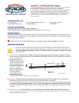
21029 Itasca st., CHATSWORTH, CALIFORNIA 91311 USA
www.CYRON.com
Multicolor LED Lighting System
Media Highlighter
HTP1502W2/HTP2402W2
Thank you for purchasing CYRON Multicolor LED Lighting System. This system will bring the latest lighting technology to
your home theatre, home décor, cabinets, and many other areas you choose. Installation of the system is simple and it can be done
by anyone with little or no electrical experience. Nonetheless, some custom installations may require professional help. Please
contact CYRON Technical Support at 818-772-1900 ext.106 for advice.
General Cautions
To reduce the risk of fire, electric shock, or injury:
Route and secure cords so that they will not be pinched or damaged
To further secure the wires, use only insulated staples or plastic ties
Not intended for recessed installations
Not intended for surface installation inside built-in furnishings
Do not install the entire system in closed compartments smaller than 4 cubic feet (26”x30”x10”)
To comply with National Electrical Code (NEC) and to prevent fire danger, run the cords where they are accessible for
examination. Cords should be visually examined periodically and immediately replaced when any damage is noted.
Contents
Please locate all system components. If any of the components are missing or damaged contact CYRON before
proceeding with installation.
1 x Controller / Hub
2 x Light bars
1 x Power supply
4 x Mounting brackets
Tapes, Hardware, Wipes
Installations
1. LIGHTBAR LOCATIONS NOTE: Depending on
many as six light bars may be used. There are many
placement. In most of the cases, the objective is to
directly visible, and its projected light is only seen.
combined colors such as white are being produced.
placement and direction of light projection. There
location.
the application, as few as one or as
intended uses and methods of light
place the light bar so it is not
This is particularly important if
Feel free to experiment with light
may be more than one good
Television Backlighting: The best location for
behind the TV, about 1 to 4 inches from the outer
Also, vertically center the bars. See TV backlighting
vary depending on the make and model of the TV.
television installations is normally
edges (left and right in most cases).
diagram. The exact location may
Cabinets, Shelving, Furniture: Typical locations are: Top or bottom of the cabinets, behind furniture trimmings, on the shelves,
and behind glass covers. Same general locations work well for most objects. There are many ways to backlight and accent light.
Try various positions to achieve the desired results.
a
CLEANING
Using the wipes provided test a small area to make sure it does not affect the mounting surfaces. Clean the
installation surfaces free of dust/grease to assure the two-sided tape adheres well.
3. MOUNTING CLIPS Mounting clips can be secured using the two-sided tape or screws. DO NOT USE SCREWS FOR
FASTENING TO ELECTRONIC DEVICES AND SENSITIVE SURFACES.
CAUTION: Tapes may cause discoloration to some surfaces over time. Remove one side of the tape liner and apply to the bottom
of the clips. Apply pressure for 5 seconds to assure adhesion. Place clips on the light bars.
4. LIGHTBAR PLACEMENT Remove the second side of tape liner. Keep the tape surface clean. Place the bars in the proper
location by pressing on the clips for 5 seconds. CAUTION: Never press on the clear lens of bars. Light bars will get damaged!
Note the direction of the wires being routed to the hub.
5. HUB Mount the hub using screws or tapes. Plug the light bar connectors into
hub outlets. The plugs are polarized and can only be plugged in one direction.
6. CONTROLLER Use tape to mount the controller in an accessible location.
Some painted surfaces may get damaged upon future removal of the
tape/controller.
7. POWER UP Plug the power supply into an AC outlet. The plug is polarized
(one blade is wider than the other) as a feature to reduce the risk of electric shock.
This plug will fit in a polarized outlet only one way. If the plug does not fit fully
in the outlet, reverse the plug. If it still does not fit, contact the factory or a
qualified electrician. Never use with an extension cord unless the plug can be
fully inserted. Do not alter the plug.
8. DC JACK Connect the DC power jack into the controller DC cord.
Operations
Turn the unit on and adjust the light angle by twisting the light bars within the brackets. Try several angles to achieve the desired
results.
Operation of HTW202 controller is simple. Color buttons on the remote correlate to the colors displayed.
Four different color shows STROBE, STEP, FADE, and COLOR automatically change light colors and patterns
with pre-programmed sequences.
1. The speed of light can be changed using the Up and Down buttons. There are 5 different speeds
available in STROBE, STEP, FADE, and COLOR modes. Brightness can also be adjusted in 5 steps. This can
only be done when displaying solid colors.
2. There are two buttons under R & G for enabling Soft Mode. First, ensure the light is off. Press the Off
button 5 times (the light should turn on). Next press the orange button to turn on Soft Mode* or the green
button to turn off Soft Mode. Simply turn off the light to save settings.
For Advanced Users Only!
3. Wiring sequences can be altered for products in which the lighting sequence doesn’t match the remote,
(the BRG sequence is selected by default.) First, ensure the light is off. Next press the off button 5 times (the
light should turn on). Then press Yellow for RGB, Blue for GRB or Pink for BRG (buttons available on last row).
Lastly turn the light off to save.
Wiring Diagram
Optional Settings
Turn LED System ON when an outlet is switched on: Plug the power supply to a switched power source such as audio receiver’s
“Switched Power” or wall outlet that is controlled by a wall switch. Make sure the outlet is switched on. Using the POWER
button on the controller, make sure the LED System is off. Press and hold the MODE button for 3 seconds. Now the unit will turn
on automatically every time the outlet is turned on.
LED System remains OFF when an outlet is switched on: In a similar process, press and hold the PAUSE button for 3 seconds.
The system will remain off every time the outlet is switched on. In this mode, the system can only be turned on from the
controller by pressing the POWER button.
Technical Support
CYRON’s primary goal is 100% customer satisfaction. You may call our technical support line or contact us via email 24/7.
[email protected]
818-772-1900 x106
In order to continually improve our products we welcome all comments about the product you purchased.
Thank You!
Cyron warrants this product against any defects in materials or workmanship for a period of ONE (1) year from the date of purchase. The warranty covers normal usage as intended by the factory
and does not cover misuse, abuse, accidents, or damages caused due to the acts of God. Proof of purchase is required.
ANY IMPLIED WARRANTIES, INCLUDING WITHOUT LIMITATION THE IMPLIED WARRANTIES OF MERCHANTABILITY AND FITNESS FOR A PARTICULAR P URPOSE,
SHALL BE LIMITED TO THE DURATION OF THIS LIMITED WARRANTY, OTHERWISE THE REPAIR, REPLACEMENT, OR REFUND AS PROVIDED UNDER THIS EXPRESS
LIMITED WARRANTY IS THE EXCLUSIVE REMEDY OF THE CONSUMER, AND IS PROVIDED IN LIEU OF ALL OTHER WARRANTIES, EXPRESS OF IMPLIED. IN NO EVENT
SHALL CYRON, INC. BE LIABLE, WHETHER IN CONTRACT OR TORT (INCLUDING NEGLIGENCE) FOR DAMAGES IN EXCESS OF THE PURCHASE PRICE OF THE
PRODUCT, ACCESSORY OR FOR ANY INDIRECT, INCIDENTAL, SPECIAL OR CONSEQUENTIAL DAMAGES OF ANY KIND, OR LOSS OF REVENUE OR PROFITS, LOSS OF
BUSINESS, OR OTHER FINANCIAL LOSS ARISING OUT OF OR IN CONNECTION WITH THE ABILITY OR INABILITY TO USE THE PRODUCTS OR ACCESSORIES TO THE
FULL EXTENT THESE DAMAGES MAY BE DISCLAIMED BY LAW.
Some states and jurisdictions do not allow the limitation or exclusion of incidental or consequential damages, or limitation on the length of an implied warranty, so the above limitations or
exclusions may not apply to you. This warranty gives you specific legal rights, and you may also have other rights that vary from state to state or from one jurisdiction to another.
Please mail all warranty claims to:
CYRON, Inc.
Warranty Claims
21029 Itasca st
Chatsworth, CA 91311 USA
Further warranty inquiries:
[email protected]
Specifications
Supply voltage range
DC Supply voltage
Controller output rating
Working Temperature
Standby power
100-240VAC, 50/60Hz
12VDC
24W nominal, 36W peak
-20 to 60ºC
<0.5W