1
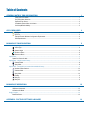
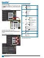
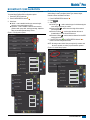
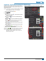
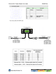
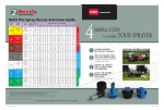
M at r i x ® P r o BoomPIlot® Setup Guide For use with software version 2.0x and 2.5x. Refer to the Matrix Pro GS User Manual for details on setup with software version 3.x. Automatic Boom Section Control Table of Contents General Matrix® Pro Information 1 Setup Option Information........................................................................................................................................................1 Drop Down Menu Selections..................................................................................................................................................1 Keyboard Entry Screen...........................................................................................................................................................2 Unavailable Options When Job is Active................................................................................................................................2 Unit Setup Mode Availability...................................................................................................................................................2 GPS is Required 3 BoomPilot Configuration 5 GPS Type.................................................................................................................................................................................3 GPS Port..................................................................................................................................................................................3 External Receiver Minimum Configuration Requirements......................................................................................................4 GGA Requirements.................................................................................................................................................................4 Vehicle Setup ......................................................................................................................................................................................................... 5 Vehicle Type.............................................................................................................................................................................6 Antenna Height ......................................................................................................................................................................6 Direction to Boom ...................................................................................................................................................................6 Distance to Boom ....................................................................................................................................................................6 Implement................................................................................................................................................................................................................ 7 Speed Out / Sense In cable............................................................................................................................................................7 Implement – Single Section Setup.................................................................................................................................................................. 7 Guidance Width ......................................................................................................................................................................8 Spray Width.............................................................................................................................................................................8 Implement – SmartCable or Section Driver Module Setup.................................................................................................................... 9 # Number of Boom Sections.....................................................................................................................................................10 Guidance Width ....................................................................................................................................................................10 Spray Width...........................................................................................................................................................................10 Overlap..................................................................................................................................................................................11 Delay On................................................................................................................................................................................11 Delay Off................................................................................................................................................................................11 BoomPilot Operation 12 SmartCable or SDM.............................................................................................................................................................................................12 Off/Manual & Automatic................................................................................................................................................................12 All Sections On Mode...................................................................................................................................................................12 Single Section.......................................................................................................................................................................................................12 BoomPilot Status..........................................................................................................................................................................13 Appendix - Factory Settings & Ranges 13 Matrix® Pro Copyrights Safety Information © 2013 TeeJet Technologies. All rights reserved. No part of this document or the computer programs described in it may be reproduced, copied, photocopied, translated, or reduced in any form or by any means, electronic or machine readable, recording or otherwise, without prior written consent from TeeJet Technologies. TeeJet Technologies is not responsible for damage or physical harm caused by failure to adhere to the following safety requirements. Trademarks The BoomPilot is not designed to replace the vehicle’s operator. Unless otherwise noted, all other brand or product names are trademarks or registered trademarks of their respective companies or organizations. Limitation of Liability TEEJET TECHNOLOGIES PROVIDES THIS MATERIAL “AS IS” WITHOUT WARRANTY OF ANY KIND, EITHER EXPRESSED OR IMPLIED. NO COPYRIGHT LIABILITY OR PATENT IS ASSUMED. IN NO EVENT SHALL TEEJET TECHNOLOGIES BE LIABLE FOR ANY LOSS OF BUSINESS, LOSS OF PROFIT, LOSS OF USE OR DATA, INTERRUPTION OF BUSINESS, OR FOR INDIRECT, SPECIAL, INCIDENTAL, OR CONSEQUENTIAL DAMAGES OF ANY KIND, EVEN IF TEEJET TECHNOLOGIES HAS BEEN ADVISED OF SUCH DAMAGES ARISING FROM TEEJET TECHNOLOGIES SOFTWARE. As the operator of the vehicle, you are responsible for its safe operation. Do not leave a vehicle while the BoomPilot is engaged. Be sure that the area around the vehicle is clear of people and obstacles before and during engagement. The BoomPilot is designed to support and improve efficiency while working in the field. The driver has full responsibility for the quality and work related results. Matrix Pro GS Software Version 3.x All information on settings to configure BoomPilot can be found in the Matrix Pro GS User Manual. General Matrix® Pro Information The Matrix Pro is used to configure the vehicle and its implements. Setup Option Information Press the option’s icon or option’s name of any menu item to display a definition and range values of that item. To remove the information box, press anywhere on the screen. Figure 1-1: Example of Information Text Box Config-> Lightbar Drop Down Menu Selections Press DOWN arrow to access the list of options. Use the UP/ DOWN arrows or slide bar if necessary to scroll through the extended list. Select the appropriate option. To close the list without selecting an option, press anywhere on the screen outside the drop down menu. Figure 1-2: Example of Drop Down Menu Config-> Vehicle Brightness Mode LED Spacing 50% Vehicle Type Front Wheel Ant Height Front Wheel 12.50 ft Articulated Swath 1.50 ft Tracked Dir to Boom LED Spacing Dist to Boom Backward 0.00 ft The distance illustrated by the illuminated LED’s can be customized. Input the desired spacing as required or individual preference. 98-05243-ENUS R2 1 BoomPilot® Keyboard Entry Screen Press the KEYPAD icon to use a numeric keypad to enter a value. Press Clear to erase the existing value. Press the ACCEPT icon to save the settings or the CANCEL icon to leave the keypad without saving Unit Setup Mode Availability Vehicle Type Vehicle – Direction to Boom Distance to Boom Figure 1-3: Example of Keyboard # Implement Front Wheel – Delay Off Enable Spray Width Overlap Delay On Ant Height Dir to Boom 12.50 ft – Backward Dist to Boom Valve Type 0.00 ft – Dist to Boom (ft) Valve Setup – Clear 4 5 6 <-- 7 8 9 – Valve Test 0 . +/- – Valve Diagnostics – Options – Angle Sensor Tilt – Enabled •Field Level GPS – Front Wheel 12.50 ft Backward Dist to Boom Config-> AutoSteer On Valve Setup Steering Settings Valve Test Valve Diagnostics www.teejet.com Fine Adjustment Lookahead – Steering Wheel Sensor GPS Type GPS Port GPS Status Ant Height 2 3 Config-> Vehicle Options – Deadband 2 Figure 1-4: Example of Unavailable Options Enabled Coarse Adjustment Steering – Settings 1 When a job is active some setup options are unavailable. See the Unit Setup Mode Availability Chart for indication of which options are not accessible. Dir to Boom Minimum Duty Cycle Left Maximum Duty Cycle Unavailable Options When Job is Active Vehicle Type Frequency Minimum Duty Cycle Right 0.00 Auto Steer Number of Sections Guidance Width Config-> Vehicle Vehicle Type Antenna Height 0.00 ft Available during an active job Not Available during an active job Matrix® Pro GPS is Required GPS is used to configure GPS Type and GPS Port. NOTE: These settings are required for auto steering and tilt sensor operation, as well as proper implement operation. 1. Press CONFIGURATION side tab . 2. Press GPS . 3. Select from: ►GPS Type – select GPS source transmissions ►GPS Port – sets (D)GPS COM port ►GPS Status – displays information for TeeJet Customer Service use on GGA/VTG (Data Rates), Number of Satellites, HDOP, PRN, GGA Quality, GPS Receiver and Receiver Version. 4. Press RETURN arrow or CONFIGURATION side tab to return to the main Configuration screen. Figure 1-5: GPS Configuration Vehicle Implement AutoSteer Tilt Lightbar GPS GPS Type GPS Type customizes the system to accept GPS source or DGPS source transmissions. 1. Press DOWN arrow to access the list of options. 2. Select: ►GPS Only – uncorrected signals ►DGPS Only – differentially corrected signals ►GPS/DGPS – either type of signal ►GPS+GLONASS – uncorrected signals from both the GPS and GLONASS systems Figure 1-6: GPS Type Config->GPS GPS Type GPS/DGPS GPS Port GPS Only Internal DGPS Only GPS Status GPS/DGPS Information GPS+GLONASS Video GPS Port Config->GPS GPS Port sets port transmission to Internal or External. GPS Type GPS/DGPS GPS Port Internal GPS Status Information 1. Press DOWN arrow to access the list of options. 2. Select: ►Internal – use the internal (D)GPS (if equipped) and transmit out ►External – receive external (D)GPS data NOTE: Working with GPS signals such as Omnistar HP/XP or RTK will require GPS port to be set to External. Figure 1-7: GPS Port Config->GPS GPS Type GPS/DGPS GPS Port Internal GPS Status Internal Information External 98-05243-ENUS R2 3 BoomPilot® GPS Status External Receiver Minimum Configuration Requirements GPS Status displays information regarding data rates, number of satellites in view, and satellite quality and ID. 1. Press Information . 2. View data including: ◄GGA/VTG (Data Rates) – the number of GPS positions per second. ◄Num Sats – the number of GPS satellites in view (minimum of 4 are required for DGPS) ◄HDOP – a measure of satellite geometry strength in the horizontal plane. A HDOP value of less than 2 is preferred. ◄PRN – the current DGPS satellite ID ◄GGA Quality – the current quality indicator of the GPS signal (see GGA chart) ◄Receiver – the current indicator of the receiver ◄Version – the software version installed on the receiver 3. Press OK to return to GPS setup screen NOTE: If GPS is not available, all entries will be “Invalid” Figure 1-8: GPS Status Config->GPS Serial Port Settings Baud rate: 19,200 Data Bits: 8 Parity: None Stop Bits: 1 Serial Port connection requirements Male 9 pin RS-232 serial cable NOTE: May require Null modem adapter depending on pin out of receiver. NMEA Strings GGA 5 Hz Optional VTG 5 Hz, 2 Hz, Off ZDA 0.2 Hz GGA Requirements GPS Type GPS/DGPS GPS Port Internal GPS Status GGA Quality required to be able to work with various types of signal can vary. See table below for requirements. Information Config->GPS GPS Type GPS Port GPS Status GPS Information GGA Rate: 5 Hz GPS/DGPS VTG Rate: 5 Hz Num Sats: 10 HDOP: 1 Internal PRN: 135 GGA Quality: 2 Receiver: 1 Information Version: OK 4 Before the Matrix will connect and work with an external GPS receiver, these minimum configuration requirements must be met. www.teejet.com Service Indicator Accuracy GPS only 1 <3 m WAAS/EGNOS/Beacon 2 <1 m RTK 4 4 cm Omnistar HP/XP 5 10 cm Glide/ClearPath 9 <1 m Matrix® Pro BoomPilot Configuration The Matrix Pro is used to configure the vehicle and its implements. To access Matrix Pro BoomPilot configuration options: 1. Press UNIT SETUP bottom tab . 2. Press CONFIGURATION side tab . 3. Select from: ►Vehicle – used to establish vehicle type, antenna height, direction to boom and distance to boom. ►Implement – used to establish number of boom sections, guidance width, spray width, overlap percentage, implement delay on time and implement delay off time. Figure 1-9: Configuration Options Configuration Vehicle Implement AutoSteer Tilt Lightbar GPS Vehicle Setup Vehicle Setup is used to configure Vehicle Type, Antenna Height, Direction to Boom and Distance to Boom. 1. Press CONFIGURATION side tab . 2. Press Vehicle . 3. Select from: – used to select the type of vehicle steering that ►Vehicle Type most closely represents your vehicle ►Antenna Height – used to enter the height of the antenna from the ground ►Direction to Boom – used to select whether the boom is located behind or in front of the GPS antenna ►Distance to Boom – used to enter the distance from the GPS antenna to the boom 4. Press RETURN arrow or CONFIGURATION side tab to return to the main Configuration screen. NOTE: All settings under Vehicle Setup are required for autosteer and tilt sensor operation, as well as proper BoomPilot operation. Figure 1-10: Vehicle Setup Options Video Configuration Config-> Vehicle Vehicle Type Front Wheel Ant Height 12.50 ft Backward Dir to Boom Vehicle Implement AutoSteer Tilt Lightbar GPS Video Config-> Vehicle Dist to Boom 0.00 ft Vehicle Type Ant Height Front Wheel 12.50 ft Config->Implement Dir to Boom Num Sections Backward 15 Dist to Boom Guidance Width 75.00 ft Spray Width 75.00 ft 0.00 ft Config->Implement (2) Overlap 50% Delay On 1.00 s Delay Off 1.00 s 98-05243-ENUS R2 5 BoomPilot® Vehicle Type Vehicle Type selects the type of vehicle steering that most closely represents your vehicle. Default is Front Wheel. 1. Press DOWN arrow 2. Select vehicle type. to access the list of options. 1. Press DOWN arrow to access the list of options. 2. Select: ►Backward – indicates the boom is located behind the GPS antenna ►Forward – indicates the boom is located in front of the GPS antenna Figure 1-13: Direction to Boom Figure 1-11: Vehicle Type Config-> Vehicle Vehicle Type Front Wheel Ant Height Front Wheel 12.50 ft Articulated Direction to Boom Direction to Boom sets whether the boom is located behind or in front of the GPS antenna as the vehicle moves in a forward direction. Default is Backward. Config-> Vehicle Tracked Backward Dir to Boom Vehicle Type Dist to Boom Front Wheel 0.00 ft Ant Height 12.50 ft Backward Dir to Boom Backward Antenna Height Antenna Height sets the height of the antenna from the ground. Range is 0.0 - 32.8 feet / 0.0 - 10.0 meters. Default is 12.5 feet / 3.81 meters. NOTE: This setting is required for auto steering and tilt sensor operation. Distance to Boom defines the distance from the GPS antenna to the boom. Range is 0.0 - 164.0 feet / 0.0 - 50.0 meters. Default is 0.0 feet / 0.0 meter. Figure 1-12: Antenna Height 1. Press the KEYPAD icon . 2. Use the entry screen to establish the distance from the GPS antenna to the boom. Config-> Vehicle Front Wheel Ant Height Dir to Boom Figure 1-14: Distance to Boom 12.50 ft Config-> Vehicle Backward Dist to Boom Vehicle Type 0.00 ft Ant Height Antenna Height (ft) 12.50 6 www.teejet.com 0.00 ft Forward Distance to Boom 1. Press the KEYPAD icon . 2. Use the entry screen to establish the antenna height. Vehicle Type Dist to Boom Dir to Boom Dist to Boom 1 2 3 Clear 4 5 6 <-- 7 8 9 0 . +/- Front Wheel 12.50 ft Backward 0.00 ft Dist to Boom (ft) 0.00 1 2 3 Clear 4 5 6 <-- 7 8 9 0 . +/- Matrix® Pro Implement Implement – Single Section Setup Settings will vary depending on if a SmartCable or Section Driver Module (SDM) is present. NOTE: If a SmartCable or Section Driver Module (SDM) is present, refer to “SmartCable or Section Driver Module Setup” to view setup steps. Implement Setup is used to establish the various settings associated with the vehicle’s implement. Speed Out / Sense In cable Implement for a single boom is used to establish guidance width and spray width. It allows the user to operate the area applied function of the Matrix Pro in series with a remote master connection or existing apply on/off toggle in a single swath manner. However if the previous connections are not available the supplied toggle switch allows area applied functionality without the need to connect to a functional application implement. 1. Press CONFIGURATION side tab . 2. Press Implement . 3. Select from: – used to enter the width between the ►Guidance Width guidelines ►Spray Width – used to enter the width of the implement 4. Press RETURN arrow or CONFIGURATION side tab to return to the main Configuration screen. The cable also sends a radar speed signal to an external device. Figure 1-16: Implement Setup Options with No SDM This cable is REQUIRED to start application mapping (painting the screen). To install your cable: Configuration • Connect using included switch (32-50008) OR • Connect green wire to master 12 Volts on/off from rate controller Figure 1-15: Speed Out / Sense In cable Vehicle Implement AutoSteer Tilt Lightbar GPS Video Config->Implement Num Sections Matrix Pro 570G 45-05765 8 Pos. Matrix Pro 840G Speed/Sense Cable 1 Guidance Width 60.00 ft Spray Width 12.00 ft ON Speed Cable 45-05615 OFF 32-50008 Switch, Master Connect Red Wire Connect Green Wire +12v Red Wire (+12v) Speed/ Status Green Wire Sense Radar Speed Out 98-05243-ENUS R2 7 BoomPilot® Guidance Width Spray Width Guidance Width establishes the width between the guidelines. Range is 34.0 - 2952.7 inches / 0.9 - 75.0 meters. Default is 60 feet / 18.29 meters. Spray Width establishes the width of the implement. Range is 34.0 2952.7 inches / 0.9 - 75.0 meters. Default is 144.0 inches (12 feet) / 3.66 meters. 1. Press the KEYPAD icon . 2. Use the entry screen to establish the guidance width. 1. Press the KEYPAD icon . 2. Use the entry screen to establish the spray width. NOTE: This setting is required for auto steering and tilt sensor operation. NOTE: This setting is required for auto steering and tilt sensor operation. Figure 1-17: Guidance Width Figure 1-18: Spray Width Config->Implement Num Sections Config->Implement Num Sections 1 1 Guidance Width 60.00 ft Guidance Width 60.00 ft Spray Width 12.00 ft Spray Width 12.00 ft Guidance Width (ft) Section 1 Width (in) 8 www.teejet.com 1 2 3 Clear 4 5 6 <-- 7 8 0 . 1 2 3 Clear 9 4 5 6 <-- +/- 7 8 9 0 . +/- Matrix® Pro Implement – SmartCable or Section Driver Module Setup Implement is used to establish number of boom sections, guidance width, spray width, overlap percentage, implement delay on time and implement delay off time. NOTE: If a SmartCable or Section Driver Module (SDM) is not present, refer to “Single Section Setup” to view setup steps. 1. Press CONFIGURATION side tab . 2. Press Implement . 3. Select from: ►Number of Boom Sections # – used to select the number of available boom sections ►Guidance Width – used to enter the width between the guidelines ►Spray Width – used to enter the width of each implement section ►Overlap – used to select the amount of overlap allowed when the boom sections are turned on and off – used to enter the timing for the boom section ►Delay On valves to switch on ►Delay Off – used to enter the timing for the boom section valves to switch off 4. Press RETURN arrow or CONFIGURATION side tab to return to the main Configuration screen. NOTE: Press or to switch between Implement setup screens. NOTE: Implement settings are only visible and necessary if a SmartCable or SDM is installed. If neither is present, see Single Boom Setup section. Figure 1-19: Implement Setup Options with SmartCable or SDM Configuration Vehicle Implement AutoSteer Tilt Lightbar GPS Video Config->Implement Num Sections 1 Guidance Width 60.00 ft Spray Width 12.00 ft Config->Implement (2) Overlap 50% Delay On 1.00 s Delay Off 1.00 s 98-05243-ENUS R2 9 BoomPilot® # Number of Boom Sections Spray Width Number of Boom Sections establishes the number of available boom sections. If a SmartCable or Section Driver Module (SDM) is present, 1 to 6 or 1 to 15 section widths can be entered (depending on which SmartCable or Section Driver Module (SDM) is detected). Default is 1. Spray Width establishes the width of each implement section. Range is 0.0 - 2952.7 inches / 0.0 - 75.0 meters. Default per section is 144.0 inches / 3.66 meters. When facing forward, boom sections are ordered from left to right along the boom. 1. Press DOWN arrow to access the list of options. 2. Select the number of boom sections on the implement: 1. 2. 3. 4. 5. Figure 1-20: Number of Boom Sections Config->Implement NOTE: When entering a boom section width, the total of all sections must be greater than 34 inches / 0.9 meters. 15 Num Sections 7 Guidance Width 8 75.00 ft NOTE: Individual boom sections can be set to different widths. 9 Figure 1-22: Spray Width 1075.00 ft 11 Spray Width Press the KEYPAD icon . Highlight the section to be established. Press the KEYPAD icon . Use the entry screen to establish the spray width. Repeat steps 2 to 4 until all sections have been established. Config->Implement 12 13 14 Num Sections 15 15 Guidance Width Guidance Width establishes the width between the guidelines. Range is 34.0 - 2952.7 inches / 0.9 - 75.0 meters. Default is 60 feet / 18.29 meters. Guidance Width 60.00 ft Spray Width 180.00 ft Config->Implement->Section Widths NOTE: This setting is required for auto steering operation. Spray Width" 75.00 ft 1. Press the KEYPAD icon . 2. Use the entry screen to establish the guidance width. Section 1 - 144.00 in Section 2 - 144.00 in Figure 1-21: Guidance Width Section 3 - 144.00 in Section 4 - 144.00 in Config->Implement Num Sections Section 5 - 144.00 in Section 6 - 144.00 in 15 Section 7 - 144.00 in Section 1 Width (in) Guidance Width 60.00 ft Spray Width 180.00 ft Guidance Width (ft) 10 www.teejet.com 1 2 3 Clear 4 5 6 <-- 7 8 9 0 . +/- 1 2 3 Clear 4 5 6 <-- 7 8 9 0 . +/- Matrix® Pro Figure 1-24: Delay On Overlap Overlap determines the amount of overlap allowed when the each boom section is turned on and off using Automatic Boom Section Control. Default is 50%. 1. Press DOWN arrow 2. Select: ►0% ►50% ►100% Figure 1-23: Overlap Config->Implement (2) Overlap to access the list of options. 50% Delay On 1.00 s Delay Off 1.00 s Delay On Time (s) Config->Implement (2) Overlap 50% 0% Delay On 50%1.00 s 100% Delay Off 1.00 s 1 2 3 Clear 4 5 6 <-- 7 8 9 0 . +/- Delay Off 0% Delay Off functions as a “look ahead” for establishing the timing for the boom section valves to switch off exactly when entering an area that has been applied. If the boom turns off too soon when entering an applied area, decrease the Delay Off setting. If the boom turns off too late when entering an applied area, increase the Delay Off setting. Range is 0.0 - 10.0 seconds. Default is 1.00 second. 50% 1. Press the KEYPAD icon . 2. Use the entry screen to establish the delay off time. 100% Figure 1-25: Delay Off Delay On Delay On functions as a “look ahead” for establishing the timing for the boom section valves to switch on exactly when entering an area that has not been applied. If the boom turns on too soon when entering a non-applied area, decrease the Delay On setting. If the boom turns on too late when entering a non-applied area, increase the Delay On setting. Range is 0.0 - 10.0 seconds. Default is 1.00 second. 1. Press the KEYPAD icon . 2. Use the entry screen to establish the delay on time. Config->Implement (2) Overlap 50% Delay On 1.00 s Delay Off 1.00 s Delay Off Time (s) 1 2 3 Clear 4 5 6 <-- 7 8 9 0 . +/- 98-05243-ENUS R2 11 BoomPilot® BoomPilot Operation SmartCable or SDM Single Section If a SmartCable or Section Driver Module (SDM) is present, , Automatic BoomPilot is used to set BoomPilot to Off/Manual . or All On NOTE: GPS is unavailable when the BOOMPILOT icon is grey BoomPilot status bar icon will be Off/Manual . . If a SmartCable or Section Driver Module (SDM) is not present, please refer to Single Section to view example. If Work On/Off Switch is in the “On” position, improper application may occur. If the individual boom section switches are in the “On” position, BoomPilot application control will not control those sections. Off/Manual & Automatic NOTE: GPS is unavailable when the BOOMPILOT icon is grey 3. Press NAVIGATION AND GUIDANCE OPTIONS icon navigation options. to display . ◄Off/Manual – Status Bar Icon will change to red ◄Automatic – Status Bar Icon will change to green In areas where application is not desired: ◄Manually turn “off” the rate controller master switch to shut off the booms. Turn the master switch “on” to resume application. . Press the BOOMPILOT icon ◄Press BOOMPILOT icon again to reseume application. All Sections On Mode To turn all sections on : 1. Press NAVIGATION AND GUIDANCE OPTIONS icon navigation options. 2. Press and hold BOOMPILOT icon . If a SmartCable or Section Driver Module (SDM) is present, please refer to SmartCable or SDM Section for more information. To switch application off or on using the console: 1. Work On/Off Switch should remain in the “Off” position. 2. Press NAVIGATION AND GUIDANCE OPTIONS icon navigation options. 3. Press BOOMPILOT icon To switch BoomPilot between off/manual and automatic : 1. Work On/Off Switch should remain in the “Off” position. 2. Turn the controller master switch to the “On” position. The individual boom section switches should remain in the “Off” position. 4. Press BOOMPILOT icon If a SmartCable or Section Driver Module (SDM) is not present, BoomPilot is used to turn all booms on or off. BoomPilot can be overridden by using the Work On/Off Switch. Only one Boom Section width will be illustrated and the Status Bar will have no icon. to display . NOTE: If the Work On/Off Switch is in the “On” position, the entire section will be activate and the BOOMPILOT icon will have no affect. If the Work On/Off Switch is not present on the system, the BOOMPILOT icon will controll the application on/off functions. In areas where application is not desired: . Press the BOOMPILOT icon ◄Press BOOMPILOT icon again to reseume application. ◄Turn the Work On/Off Switch to the “On” position and back to the “Off” position. Turn the Work On/Off Switch “on” to resume application. Figure 1-27: All Booms Off/On – No SDM 0.0 mph Mark A to display 0.00 ac A A . ◄All On – Status Bar Icon will change to yellow Figure 1-26: Automatic to All Sections On Mode 0.0 mph Mark A 0.00 ac A A 12 www.teejet.com 7.0 km/h Mark A 0.02 ac Matrix® Pro BoomPilot Status BoomPilot Status displays information regarding the current status of the BoomPilot system. to view the number of sections. 1. Press BOOMPILOT STATUS icon -13 Mark A 7.2 mph BoomPilot Status Red = Off/Manual Green = Automatic Yellow = All On No icon = Single Boom Section (no SmartCable or SDM installed on system) Num Sections: 15 Appendix - Factory Settings & Ranges Vehicle Setup Settings Description Factory Setting Range Vehicle Type Front Wheel Antenna Height 12.0 ft / 3.66 m Direction to Boom Forward Boom Offset Distance 0.0 ft / 0.0 m 0.0 - 164.0 ft / 0.0 - 50.0 m Description Factory Setting Range Number of Boom Sections 1 1-15 Guidance Width 60.0 ft / 18.29 m 3.28 - 246.1 ft / 1.0 - 75.0 m Spray Width 12.0 ft / 3.66 m 3.28 - 246.1 ft / 1.0 - 75.0 m Boom Section Width(s) 144.0 in / 3.66 m 0.0 - 2952.7 in / 0.0 - 75.0 m Overlap 50% Delay Off 1.0 s 0.0-10.0 s Delay On 1.0 s 0.0-10.0 s User Settings 0.0 - 32.8 ft / 0.0 - 10.0 m Implement Setup Settings User Settings 98-05243-ENUS R2 13 M at r i x ® P r o BoomPilot® Setup Guide This guide contains the instructions to setup the automatic boom section control (ABSC) or BoomPilot options on the vehicle through the Matrix Pro console. Please review this manual thoroughly after completing the installation process. 1801 Business Park Drive Springfield, Illinois 62703 USA www.teejet.com 98-05243-ENUS R2 English/US © TeeJet Technologies 2013