1
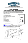
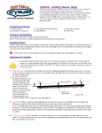
www.CYRON.com Multicolor LED Lighting Media Highlighter® HTP904E CAUTION IMPORTANT SAFETY INSTRUCTIONS This portable luminaire may have been supplied with a polarized plug (one blade is wider than the other) as a feature to reduce the risk of electric shock. If so, this plug will fit in a polarized outlet only one way. If the plug does not fit fully in the outlet, reverse the plug. If it still does not fit, contact a qualified electrician. Never use with an extension cord unless plug can be fully inserted. Do not alter the plug. 1 Español page 6 www.CYRON.com Multicolor LED Lighting Media Highlighter® HTP904E Thank you for purchasing CYRON HTP904E Multicolor LED Lighting System. This system will bring the latest lighting technology to your home theatre, home décor, cabinets, and many other areas you choose. Installation of the system is simple and it can be done by anyone with little or no electrical experience. Nonetheless, some custom installations may require professional help. Please contact CYRON Technical Support for advice. General Cautions To reduce the risk of fire, electric shock, or injury: Route and secure cords so that they will not be pinched or damaged To further secure the wires, use only insulated staples or plastic ties Not intended for recessed installations Not intended for surface installation inside built-in furnishings Do not install the entire system in closed compartments smaller than 4 cubic feet (26”x30”x10”) To comply with National Electrical Code (NEC) and to prevent fire danger, run the cords where they are accessible for examination. Cords should be visually examined periodically and immediately replaced when any damage is noted. Contents Please locate all system components. If any of the components are missing or damaged contact CYRON before proceeding with installation. 1 x Controller/Hub, HTC110A 4 x Lightbars 9" 1 x Power supply 12W 8 x Mounting brackets Tapes, Hardware, Wipes 2 Installations 1. LIGHTBAR LOCATIONS NOTE: Depending on the application, as few as one or as many as six lightbars may be used. There are many intended uses and methods of light placement. In most of the cases, the objective is to place the lightbar so it is not directly visible, and its projected light is only seen. This is particularly important if combined colors such as white are being produced. Feel free to experiment with light placement and direction of light projection. There may be more than one good location. Television Backlighting: The best location for television installations is normally behind the TV, about 1 to 4 inches from the outer edges (left and right in most cases). Also, vertically center the bars. See TV backlighting diagram. The exact location may vary depending on the make and model of the TV. Cabinets, Shelving, Furniture: Typical locations are: Top or bottom of the cabinets, behind furniture trimmings, on the shelves, and behind glass covers. Same general locations work well for most objects. There are many ways to backlight and accent light. Try various positions to achieve the desired results. 3 a 2. CLEANING Using the wipes provided test a small area to make sure it does not affect the mounting surfaces. Clean the installation surfaces free of dust/grease to assure the two-sided tape adheres well. 3. MOUNTING CLIPS Mounting clips can be secured using the two-sided tape or screws. DO NOT USE SCREWS FOR FASTENING TO ELECTRONIC DEVICES AND SENSITIVE SURFACES. CAUTION: Tapes may cause discoloration to some surfaces over time. Remove one side of the tape liner and apply to the bottom of the clips. Apply pressure for 5 seconds to assure adhesion. Place clips on the lightbars. 4. LIGHTBAR PLACEMENT Remove the second side of tape liner. Keep the tape surface clean. Place the bars in the proper location by pressing on the clips for 5 seconds. CAUTION: Never press on the clear lens of bars. Lightbars will get damaged! Note the direction of the wires being routed to the hub. 5. HUB Mount the hub using screws or tapes. Plug the lightbar connectors into hub outlets. The plugs are polarized and can only be plugged in one direction. 6. CONTROLLER Use tape to mount the controller in an accessible location. Some painted surfaces may get damaged upon future removal of the tape/controller. 7. POWER UP Plug the power supply into an AC outlet. The plug is polarized (one blade is wider than the other) as a feature to reduce the risk of electric shock. This plug will fit in a polarized outlet only one way. If the plug does not fit fully in the outlet, reverse the plug. If it still does not fit, contact the factory or a qualified electrician. Never use with an extension cord unless the plug can be fully inserted. Do not alter the plug. 8. DC JACK Connect the DC power jack into the controller DC cord. Operations Turn the unit on and adjust the light angle by twisting the lightbars within the brackets. Try several angles to achieve the desired results. 4 “MODE” button cycles through 14 functions as shown in the diagram. Press of a button is confirmed by a short fast blink of the Indicator Light. “PAUSE” button will stop the color transition in any of the color transition or color fade modes. Optional Settings Turn LED System ON when an outlet is switched on: Plug the power supply to a switched power source such as audio receiver’s “Switched Power” or wall outlet that is controlled by a wall switch. Make sure the outlet is switched on. Turn off the system using the POWER button. Press and hold the MODE button for 3 seconds. Now the unit will turn on automatically every time the outlet is turned on. LED System remains OFF when an outlet is switched on: In a similar process, press and hold the PAUSE button for 3 seconds. The system will remain off every time the outlet is switched on. In this mode, the system can only be turned on from the controller by pressing the POWER button. 5 Technical Support CYRON’s primary goal is 100% customer satisfaction. You may call our technical support line or contact us via email 24/7. [email protected] 818-772-1900 x106 In order to continually improve our products we welcome all comments about the product you purchased. Thank You! Warranty Cyron warrants this product against any defects in materials or workmanship for a period of ONE (1) year from the date of purchase. The warranty covers normal usage as intended by the factory and does not cover misuse, abuse, accidents, or damages caused due to the acts of God. Proof of purchase is required. ANY IMPLIED WARRANTIES, INCLUDING WITHOUT LIMITATION THE IMPLIED WARRANTIES OF MERCHANTABILITY AND FITNESS FOR A PARTICULAR PURPOSE, SHALL BE LIMITED TO THE DURATION OF THIS LIMITED WARRANTY, OTHERWISE THE REPAIR, REPLACEMENT, OR REFUND AS PROVIDED UNDER THIS EXPRESS LIMITED WARRANTY IS THE EXCLUSIVE REMEDY OF THE CONSUMER, AND IS PROVIDED IN LIEU OF ALL OTHER WARRANTIES, EXPRESS OF IMPLIED. IN NO EVENT SHALL CYRON, INC. BE LIABLE, WHETHER IN CONTRACT OR TORT (INCLUDING NEGLIGENCE) FOR DAMAGES IN EXCESS OF THE PURCHASE PRICE OF THE PRODUCT, ACCESSORY OR FOR ANY INDIRECT, INCIDENTAL, SPECIAL OR CONSEQUENTIAL DAMAGES OF ANY KIND, OR LOSS OF REVENUE OR PROFITS, LOSS OF BUSINESS, OR OTHER FINANCIAL LOSS ARISING OUT OF OR IN CONNECTION WITH THE ABILITY OR INABILITY TO USE THE PRODUCTS OR ACCESSORIES TO THE FULL EXTENT THESE DAMAGES MAY BE DISCLAIMED BY LAW. Some states and jurisdictions do not allow the limitation or exclusion of incidental or consequential damages, or limitation on the length of an implied warranty, so the above limitations or exclusions may not apply to you. This warranty gives you specific legal rights, and you may also have other rights that vary from state to state or from one jurisdiction to another. Please mail all warranty claims to: CYRON, Inc. Warranty Claims 21029-C Itasca St. Chatsworth, CA 91311 USA Further warranty inquiries: [email protected] Specifications Supply voltage range System power DC Supply current rating Controller output rating Working Temperature Standby power 100-240VAC, 50/60Hz 2.5W nominal, 6W max (4 lights) 1A max at 12VDC 24W nominal, 36W peak -20 to 60ºC <0.5W 6 Español www.CYRON.com Multicolor LED Lighting Media Highlighter® HTP904E Gracias por comprar Cyron HT904E Sistema de iluminación LED. Este sistema traerá lo último en tecnología de iluminación para cine en casa, el hogar decoración, muebles, y muchas otras áreas que usted elija. La instalación del sistema es sencillo y puede hacerse por cualquier persona con poca o ninguna experiencia en electricidad. la experiencia. Sin embargo, algunas instalaciones personalizadas pueden requerir ayuda profesional. Por favor, póngase en contacto con Soporte técnico en la Cyron 818-772-1900 ext.106 para pedir consejo. Precauciones Generales Para reducir el riesgo de incendio, Toques eléctricos o lesiones: Guie y asegure los alambres para que no se pinchen o dañen. A fin de asegurar los cables, use solamente grapas con aislamiento o plástico No está diseñado para instalaciones empotradas No está diseñado para instalación en superficie en el interior integrado en el mobiliario No instale el sistema completo en compartimentos cerrados de menos de 4 pies cúbicos (26 "x30" x10 ") Para cumplir con el Código Eléctrico Nacional (NEC) y para prevenir el peligro de incendios, instale los cables donde sean accesibles para su revision., Los cables deben ser examinados visualmente periódicamente y sustituir de inmediato cuando se note algún daño. 7 Instalaciones 1. COLOCACION de el Lightbar NOTA: Dependiendo de la aplicación, tan sólo uno o hasta seis lightbars puede ser utilizado. Hay muchos usos previstos y los métodos de colocación de la luz. En la mayoría de los casos, el objetivo es colocar la barra de luz donde no sea directamente visible, y su luce proyectada sólo se vea. Siéntase libre de experimentar con la colocación de la luz. Puede haber más de un lugar deseado. Televisión luz de fondo: La mejor ubicación para las instalaciones de la televisión es normalmente detrás de la TV, de 1 a 4 pulgadas de los bordes exteriores (a la izquierda y derecho en la mayoría de los casos). Además, el centro vertical de las barras. Ver diagrama de TV luz de fondo. La ubicación exacta puede variar dependiendo de la marca y modelo del televisor. Armarios, estanterías, muebles: lugares típicos son: el vidrio superior o inferior de los armarios, detrás de recortes de muebles, en los estantes, y detrás de los cubre vidrios.En la misma ubicación general funcionan bien para la mayoría de los objetos. Hay muchas maneras de luz de fondo y la luz de acento. Pruebe distintas posiciones para lograr los resultados deseados. 2. LIMPIEZA, a Usando las toallitas proporcionadas, pruebe una superficie pequeña para asegurarse de que no afecte a las superficies de montaje. Limpiee las 8 superficies de instalación para que queden libres de polvo o grasa y asi asegurar que la cinta se adhiera bien por las dos caras. 3. CLIPS Clips de montaje de montaje se pueden sujetar con la cinta de doble cara o tornillos. No utilice tornillos de fijación al Dispositivos electrónicos y superficies delicadas. PRECAUCIÓN: Cintas puede causar decoloración en algunas superficies con el tiempo. Quite un lado de la cinta protectora y se aplican a la parte inferior de los clips. Aplique presión durante 5 segundos para asegurar la adherencia. Coloque los soportes en el lightbars. 4. COLOCACIÓN del Lightbar Quitar la segunda cara de la cinta protectora. Mantenga la superficie de la cinta limpia. Coloque las barras en el lugar adecuado ejerciendo presion sobre los clips por 5 segundos. PRECAUCIÓN: nunca presione en el lado transparente de las barras. Lightbars se dañaran! Fíjese en la dirección de los cables que se dirigen al concentrador. 5. HUB., Monte el eje mediante tornillos o cintas. Conectar los conectores del puente de luces en las tomas de cubo. Los enchufes están olarizados y sólo puede ser enchufado una dirección. 6. CONTROLADOR., Utilice cinta adhesiva para montar el controlador en un lugar accesible. En la pared detrás de la TV, las paredes exteriores de los gabinetes son posibles y buenos lugares. PRECAUCIÓN: Algunas superficies pintadas podrían dañarse si se retira en el futuro la cinta/controlador. 7. ENCIENDALO., Conecte la fuente de alimentación a una toma de CA. El enchufe está polarizado (una pata más ancha que la otra) como una función para reducir el riesgo de descarga eléctrica. Este enchufe encajará en un tomacorriente polarizado de una sola manera. Si el enchufe no encaja completamente en el tomacorriente, invierta el enchufe. Si aún así no entra, llame a la fábrica oa un electricista calificado. Nunca se debe usar un cable de extensión a menos que el enchufe pueda insertarse por completo. No altere el enchufe. 8. JACK DC Conecte el conector de alimentación de CC en el cable del control DC. 9 Operacion Encienda la unidad y ajustar el ángulo de luz girando la lightbars dentro de los corchetes. Pruebe diferentes ángulos para lograr los resultados deseados. "MODE" ciclos de botón a través de las siete funciones, como se muestra en el diagrama. Pulse un botón se confirma por un parpadeo rápido del indicador a corta Luz. La música es la luz más fáciles de distinguir cuando las luces estroboscópicas y cambian de color con el sonido. "PAUSE" se detendrá el color transición en cualquiera de los seis modos distintos de música ligera. Ajustes Opcionales Encienda el SISTEMA LED cuando la toma está encendida: Conecte la fuente de alimentación a una fuente de alimentación conmutada como "Switched POWER “ receptor de audio Power "o toma de corriente que es controlado por un interruptor de pared. Asegúrese de que la toma está encendida. Con el botón POWER en el controlador, Asegúrese de que el sistema esté apagado. Mantenga oprimida la tecla MODE durante 3 segundos. Ahora, la unidad se activará automáticamente cada vez que la salida está activada sucesivamente., el sistema LED permanecerá apagado cuando la toma de corriente este encendida: En un proceso similar, presione y mantenga presionado el botón de pausa de 3 segundos. El sistema permanecerá apagado cada vez que encienda el switch. En este modo, el sistema sólo se puede activar desde el controlador pulsando el botón POWER. Soporte Tecnico Correo electrónico: [email protected] Teléfono: +1-818-772-1900 x106 10 Garantía Cyron garantiza este producto contra cualquier defecto en los materiales o mano de obra por un período de UN (1) año desde la fecha de compra. La garantía cubre el uso normal según lo previsto por la fábrica y no cubre mal uso, abuso, accidentes o los daños causados por los actos de Dios. La prueba de la compra es necesaria. Cualquier garantía implícita, incluyendo sin limitación, LAS GARANTÍAS IMPLÍCITAS DE COMERCIALIZACIÓN Y APTITUD PARA UN PROPÓSITO PARTICULAR, se limitara a LA DURACIÓN DE ESTA GARANTÍA LIMITADA, OTRO la reparación, reemplazo o el reembolso, PREVISTO DE LA GARANTIA LIMITADA EXPRESS, Es el recurso exclusivo del consumidor, y se proporciona EN LUGAR DE CUALQUIER OTRA GARANTIA, EXPRESS DE IMPLÍCITA. EN NINGÚN CASO, Cyron, Inc. será responsable, ya sea contractual o extracontractual (INCLUYENDO NEGLIGENCIA) POR DAÑOS EN EXCESO DE LA precio de compra del producto, accesorio, O POR DAÑOS INDIRECTOS, ACCIDENTALES, especiales o consecuentes daños y perjuicios de cualquier tipo, o pérdida de ingresos O BENEFICIOS, pérdida de negocio, u otras pérdidas financieras derivadas de o en conexión con La capacidad o incapacidad de utilizar los productos o accesorios en toda la extensión ESTOS DAÑOS PUEDE ser denegadas POR LA LEY. Algunos estados y jurisdicciones no permiten la limitación o exclusión de daños incidentales o consecuentes, o la limitación de la duración de una garantía implícita, así que las limitaciones o exclusiones anteriores pueden no aplicarse a usted. Esta garantía le otorga derechos legales específicos, y usted también puede tener otros derechos que varían de estado a estado o de una jurisdicción a otra. Por favor envíe todos los reclamos por garantía a: CYRON, Inc. HT reclamo de garantía 21029-C St. Itasca Chatsworth, CA 91311 EE.UU. Otras investigaciones garantía: [email protected] 11 Optional accessories & other compatible CYRON products: LIGHTS, RIGID LIGHTBARS Expansion Lights, 2x9" 15ft cords, 2.2W Expansion Lights, 2x9" 5ft cords, 2.2W Expansion Lights, 2x15" 15ft cords, 5W Expansion Lights, 2x24" 15ft cords, 9W LIGHTS, FLEXIBLE RIBBONS HTPR-RL 16.5ft, Indoor grade IP20, 12VDC 30W, consult factory HTPRZ-RL 16.5ft, outdoor grade IP67, 12VDC 30W, consult factory HTPRX-RL 16.5ft, outdoor grade IP68, 12VDC 30W, consult factory HTPR-2H-24RL 16.5ft, indoor PRO grade IP20, 24VDC 60W, consult factory HTPRZ-2H-24RL 16.5ft, outdoor PRO grade IP67, 24VDC 60W, consult factory FLOOD LIGHTS BFL10-RGB Flood light IP67, 100-240VAC 10W, consult factory BFL30-RGB Flood light IP67, 100-240VAC 30W, consult factory BFL50-RGB Flood light IP67, 100-240VAC 50W, consult factory CONTROLLERS HTC110A Wired, 6-port Hub, Music lgt, 12VDC 30W HTW310RF Wireless RF, 6-port hub, 6-button remote, 12/24VDC 100/200W HTW202 Wireless IR, hub optional, 24-button remote, 12/24VDC 80W HTW202B Wireless IR, 6-port hub, 24-button remote, 12/24VDC 80W HTW1000 Wireless IR, 12-port hub 30-button remote, 12VDC 140W HTW1010 Wireless IR, 12-port hub 30-button remote, 12/24VDC 240/480W HARDWARE/CORDS CLIPS-MH Mounting clips for Lightbar, Tapes, 4pcs CON-HT10 10ft (3m) extension cord for lightbars, 1 max per light CON-DC4EXT 4ft extension cord, power supply to controllers, 1 maximum POWER SUPPLIES PS12-SP12D 100-240VDC, 12VDC 1A, Wall plug type PS18-SP12D 100-240VAC, 12VDC 1.5A, Desktop type, AC cord PS30-SP12DS 100-240VDC, 12VDC 2.5A, Desktop type, AC crd, On/Off switch PS50-SP12D 100-240VDC, 12VDC 4.17A, Desktop type, AC cord HTPB9 HTPB9-5 HTPB15 HTPB24 CYRON, Inc. 21029-C Itasca Street Chatsworth, CA 91311 USA 818-772-1900 www.CYRON.com [email protected] © Copyright CYRON, Inc. 2013 12