1
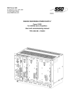
DIGIVEX - "SSI" ABSOLUTE ENCODING
CONTENTS
SAFETY INSTRUCTIONS
……………………………………………………………………………2
1.
GENERAL
4
2.
OPERATION
4
2.1 TYPE OF POSITION SIGNAL
2.2 SIGNAL CHARACTERISTICS
2.2.1
Transmission speed
2.2.2
Signal level
2.3 MEMORIZATION OF THE "POSITION FAULT" DIAGNOSIS SIGNAL POSITION
2.4 SOFT LIMIT - ORIGIN DEFINED BY LOGIC INPUTS
2.4.1
Origin setting defined
2.4.2
Software LIMITS
3.
PARAMETER INPUT
9
3.1 VIA DIGIVEX-PC SOFTWARE
3.1.1
SOFTWARE DESCRIPTION
3.1.1.1
Travail "OFF LINE"
3.1.1.2
Working "ON-LINE"
3.2 VIA DTP001 CONSOLE
3.3 PARAMETER FUNCTIONS AND VALUES
4.
CONNECTIONS / STRAP POSITIONS
4.1
4.2
4.3
4.4
4
5
5
5
6
6
6
8
SC 6637 RUB 1 CARD
SC 6637 RUB 2 CARD
WIRING REQUIREMENTS
ST1/ST2 STRAP POSITIONS
9
9
9
10
11
12
13
13
14
15
15
Characteristics and dimensions subject to change without notice.
YOUR LOCAL CORRESPONDENT
SSD Parvex SAS
8 Avenue du Lac / B.P 249 / F-21007 Dijon Cedex
Tél. : +33 (0)3 80 42 41 40
Fax : +33 (0)3 80 42 41 23
www.SSDdrives.com
1
PVD 3488 GB 01/2003
DIGIVEX - "SSI" ABSOLUTE ENCODING
SAFETY
Servodrives present two main types of hazard :
- Electrical hazard
Servoamplifiers may contain non-insulated live AC or DC
components. Users are advised to guard against access to live
parts before installing the equipment.
Even after the electrical panel is de-energized, voltages may be
present for more than a minute, until the power capacitors have
had time to discharge.
Specific features of the installation need to be studied to prevent
any accidental contact with live components :
- Connector lug protection ;
- Correctly fitted protection and earthing features ;
- Workplace insulation
(enclosure insulation humidity, etc.).
General recommendations :
• Check the bonding circuit;
• Lock the electrical cabinets;
• Use standardised equipment.
- Mechanical hazard
Servomotors can accelerate in milliseconds. Moving parts must be
screened off to prevent operators coming into contact with them.
The working procedure must allow the operator to keep well clear
of the danger area.
All assembly and commissioning work must be done by qualified
personnel who are familiar with the safety regulations (e.g. VDE
0105 or accreditation C18510).
2
PVD 3488 GB 01/2003
DIGIVEX - "SSI" ABSOLUTE ENCODING
Upon delivery
All servoamplifiers are thoroughly inspected during manufacture and tested at length before
shipment.
•
•
Unpack the servoamplifier carefully and check it is in good condition.
Also check that data on the manufacturer's plate comries with data on the order
acknowledgement.
If equipment has been damaged during transport, the addressee must file a complaint with the
carrier by recorded delivery mail within 24 hours.
Caution :
The packaging may contain essential documents or accessories, in particular :
• User Manual,
• Connectors.
Storage
Until installed, the servoamplifier must be stored in a dry place safe from sudden temperature
changes so condensation cannot form.
Special instructions for setting up the equipment
CAUTION
For this equipment to work correctly and safely it must be
transported, stored, installed and assembled in accordance with
this manual and must receive thorough care and attention..
Failure to comply with these safety instructions may lead to
serious injury or damage.
The cards contain components that are sensitive to electrostatic
discharges. Before touching a card you must get rid of the static
electricity on your body. The simplest way to do this is to touch a
conductive object that is connected to earth (e.g. bare metal
parts of equipment cabinets or earth pins of plugs).
3
PVD 3488 GB 01/2003
DIGIVEX - "SSI" ABSOLUTE ENCODING
1. GENERAL
This option is designed to provide serial information about absolute position sychronized with an
externally generated (by Numerical Control) timing signal (CLOCK).
The option is configured in part by straps on the card and via the DIGIVEX-PC software.
This is a highly valuable option if the motor is fitted with a holding brake.
Two cards have been developed:
• SC 6637- RUB 1 card: provides absolute position encoding only.
• SC 6637 - RUB 2 card: provides encoding and software inputs / outputs for origin
(home position) setting and software.
2. OPERATION
2.1 TYPE OF POSITION SIGNAL
The absolute position is encoded on 24 bits, in binary or Gray code depending on the position of strap ST1.
• ST1 in position BIN: binary code
• ST1 in position GRAY: Gray code
Default setting when shipped: Gray code
The position signalling sequence is as follows:
T
CLOCK
Tm
DATA
1
1
G23
A
B
G22
G21
G20
GØ
C
4
PVD 3488 GB 01/2003
PFB
DIGIVEX - "SSI" ABSOLUTE ENCODING
The external clock is at level 1 between two position measurements.
The occurrence, at A, of the first negative-going edge clock input causes the position to be
memorized (acknowledgement time: 0.3 µs).
Tm = 17 µs.
One binary or Gray code bit is transmitted over the line for each positive-going edge clock input,
beginning with the most significant bits.
G23 = most significant bit,
GØ = least significant bit.
After the least significant bit, a PFB location is reserved for a parity check, which is not validated
in the current version (bit is set to Ø by default, to 1 on request).
The absolute position transmitted is cross-referenced to an origin (home position) obtained by a
special resetting or origin setting sequence (via logic inputs or via software).
2.2 SIGNAL CHARACTERISTICS
2.2.1 Transmission speed
• Maximum clock speed: 1.5 MHz.
This frequency is limited by the line transmission times (RS422 type).
• Minimum clock speed : 80 kHz
Line
length
50 m
100 m
Maximum frequency
kHz
400 kHz
300 kHz
Minimum transmission time
of one position
92,5 µs
114 µs
• Minimum inter-frame time (time between end of transmission and next transmission
request): depending on solder tag Y2.
Y2 in position 1-2: 17 µs (default option),
Y2 in position 2-3: 0,66 µs.
Consult the manufacturer about any changes to Y2.
The actual time between two position requests is, of course, externally controlled by the
positioning system request.
2.2.2 Signal level
EIA RS 422 type signal.
The output signal is galvanically isolated from the DIGIVEX. The output interface must have either
a 5 V or a 24 V power supply, depending on the position of strap ST2.
ST2 in 5 V position : external supply 5 V ± 5%, max. 50 mA
ST2 in 24 V position : external supply 24 V ± 5%, max. 50 Ma
5
PVD 3488 GB 01/2003
DIGIVEX - "SSI" ABSOLUTE ENCODING
2.3 MEMORIZATION OF THE "POSITION
DIAGNOSIS SIGNAL POSITION
FAULT"
Whenever the auxiliary power supply fails, the absolute position is backed up in an EEPROM.
When power is restored, the actual position is read off and compared with the stored position. If
the observed motion is less than a programmed limit, the memorized position is updated.
ATTENTION: Even when within this limit, the system does not detect any offset of an integral
number of resolver resolutions.
For safety:
•
The motor must be fitted with a brake and declared as such when customizing
the DIGIVEX.
• In the event of a main power failure, the electronic card checks :
♦ that there is no longer a 24 V supply to the brake,
♦ that the motor speed is ≤ 50 rpm.
A "position fault" diagnosis is signalled and can be read by the DIGIVEX-PC in the following cases:
• In the event of a main failure:
♦ motor declared without brake,
♦ or motor speed > 50 rpm,
♦ or 24 V supply still applied to brake.
• When power is restored:
♦ position outside programmed limit.
This fault causes the drive axis to be set to software zero torque (T = 0] and the
ETATPOM output to switch to 1, without the OK relay opening.
• Resolver fault on drive axis.
To reactivate the servo drive and clear the fault, an origin reset must be performed and torque
set in the software.
2.4 SOFT LIMIT - ORIGIN DEFINED BY LOGIC INPUTS
The SC 6637 RUB 2 card has two logic inputs and three logic outputs, which are 24 V optoisolated. For the physical definition of these outputs, see the DIGIVEX digital servoamplifier
instructions - PVD 3464 GB § 4.4.4 and DIGIVEX POWER DRIVE (single-axis) PVD 3484 GB.
2.4.1 Origin setting defined
The origin setting sequence may be conducted:
• either via software (see §3),
• or via two logic inputs and one logic output.
6
PVD 3488 GB 01/2003
DIGIVEX - "SSI" ABSOLUTE ENCODING
The principle is identical in both cases :
• release the drive: set to zero torque and open brake,
CAUTION: Check that there are no mechanical hazards , especially for vertical drive axes.
• position the motor manually,
• declare that the current mechanical position has a value set by the "ORIGIN"
parameter (which may be Ø or any other value between the minimum and
maximum possible).
Origin setting sequence via logic inputs/outputs (accessible with SC 6637 RUB 2 only)
•
•
•
•
MODE
Open the brake and set the servo drive to zero torque (CAUTION: beware of
possible mechanical consequences).
Move the drive manually to the desired position.
Set the "MODE" input to 1 to request the resetting sequence.
Validate by a positive- or negative-going edge on the "Validate Reset" input.
1
0
ETATPOM
VALIDATE
ORIGIN SETTING
The actual position is overridden and set to the programmed value.
MODE
1
0
ETATPOM
VALIDATE ORIGIN SETTING
These inputs can be driven by the same
signal
7
PVD 3488 GB 01/2003
DIGIVEX - "SSI" ABSOLUTE ENCODING
ATTENTION: Any positive- or negative-going edge is acknowledged when validating the origin.
The ETATPOM output is in logic state 1 when the Origin Setting is validated. It is in logic
state Ø when a resetting sequence is required (as when "Position Fault" arises).
2.4.2 Software LIMITS
A maximum stroke in positive and negative directions can be programmed via the DIGIVEX-PC
with the SSI option validated.
Reaching either of the two soft limits:
• prevents the drive axis from moving further, by setting the servo drive software to zero speed in
the relevant direction (CW= 0 or CCW = 0);
• sets the corresponding limit of travel output to 1 logic state (transistor conducting).
0
M LIMIT (Minus)
P LIMIT (Plus)
Axe X
M LIMIT
output
P LIMIT
output
zero speed negative
direction
zero speed
positive direction
ATTENTION: The software limits are cross-referenced to the position origin and therefor related
to the origin setting.
After all origin setting sequences, check that the mechanical position of the
software stops is correct.
8
PVD 3488 GB 01/2003
DIGIVEX - "SSI" ABSOLUTE ENCODING
3. PARAMETER INPUT
3.1 VIA DIGIVEX-PC SOFTWARE
3.1.1 SOFTWARE DESCRIPTION
The SSI section can be accessed via the "ENCODER" menu of the DIGIVEX-PC software, in
level 2 only (password as required).
3.1.1.1 Travail "OFF LINE"
The SSI parameters may be included in a parameter file and then loaded via a total transfer.
Access is obtained:
• either by double-clicking on the encoder picture,
• or via PARAMETERS + ENCODER.
A window is displayed where either the encoder or the SSI option may be selected.
Selecting SSI opens the following parameter window:
Press "OK" to validate all the SSI parameters.
See § 3.2 for parameter definitions.
9
PVD 3488 GB 01/2003
DIGIVEX - "SSI" ABSOLUTE ENCODING
When working "OFF LINE", clicking on "ORIGIN SETTING" allows access to the window below
only, allowing the direction of increasing positions to be chosen: "OFF LINE", the origin setting
sequence is meaningless and is not acknowledged.
Press "OK" to validate the parameters and return to the "SSI Card Definition" window.
3.1.1.2 Working "ON-LINE"
When the PC-DIGIVEX connection is made, the software acknowledges the SSI option is available.
• Total transfer with SSI :
Identical to total transfer without SSI, except that the origin must be reset.
• Parameter modification "ON LINE" :
The system provides access to the same windows :
♦ either by double-clicking on the "ENCODER" disc: this opens the SSI
parameter window directly as the software has acknowledged the option is
available.
♦ or via PARAMETERS + ENCODER.
♦ Clicking on "ORIGIN SETTING" sets the DIGIVEX drive software to zero
torque (T = 0), after confirmation.
♦ Clicking "OK" calls up the SSI Origin Setting window, which is identical to the
one seen in the "OFF LINE" section.
10
PVD 3488 GB 01/2003
DIGIVEX - "SSI" ABSOLUTE ENCODING
•
Software origin setting sequence:
The software origin setting sequence is as follows:
♦ If required, before setting to zero torque, approach in numerical control
manual mode.
♦ Call up the SSI window, then the "Origin Setting" section - confirm set to zero
torque.
♦ Move manually at zero torque to the desired position.
♦ Confirm by "OK". The "ORIGIN" value, and clockwise / counter clockwise
directions are then acknowledged and the "Origin Setting Completed" output
validated.
♦ Reset the servo drive torque via the DIGIVEX-PC "Input Assignment" window.
TAKE CARE: Origin must be reset after any change to parameters "ON-LINE" or any total
transfer.
3.2 VIA DTP001 CONSOLE
The SSI parameter setting option can be accessed in Parameter Group No. 6.
The PARAM key and (Í and Î) keys are used to shift from one parameter to the next.
SSI option set-up:
• Current position
• Resolution
• Programming unit
• Origin position
• Plus stop
• Minus stop
• Counting direction
•
•
PU
position via motor revolutions
PU
PU
PU
CW (clockwise)
CCW (counter-clockwise)
Maximum permitted motion with power off PU
Origin setting
PU: Programming Unit
"Default Position" is displayed as SSI FAULT
11
PVD 3488 GB 01/2003
DIGIVEX - "SSI" ABSOLUTE ENCODING
3.3 PARAMETER FUNCTIONS AND VALUES
•
Resolution: number of absolute positions encoded per motor revolution:
Value : 4 to 65 532
Variation
: 4 by 4.
•
Programming unit: Value in units (mm, rev., degrees, etc.) for one motor
revolution.
Maximum value
: as for resolution
Minimum value
:0
Digital value : 8 digits, floating decimal.
ATTENTION: Unit programming is a feature provided for entering values in the absolute encoder
card. The value actually transmitted is not in units: it is a code (binary or Gray)
depending on the number of revolutions and the resolution per revolution.
•
Current position:
•
Maximum motion authorized when power off:
Maximum value: ± 0.1 motor revolutions, converted into units. This value is
intended to monitor any motion while power off.
•
Origin setting: in units
Value introduced when the origin setting sequence is validated (by logic input or
software).
23
Maximum value: corresponds to 2 + 1 codes
23
Minimum value: corresponds to -2 - 1 codes
Value related to 24 bit signal, to resolution and to unit value.
•
Plus LIMIT - Minus LIMIT
Values in units corresponding to the maximum desired stroke. They are crossreferenced to the origin position.
Maximum values: related, as for resetting, to 24 bits, to the unit and to the
resolution.
•
Counting direction:
♦ Clockwise CW: clockwise rotation of the motor shaft viewed from the shaft end
increments the absolute position (default value).
present value, in units.
♦ Counter clockwise CCW: counter clockwise rotation of the motor shaft viewed
from the shaft end decrements the absolute position.
ATTENTION: A change in the clockwise counter clockwise direction reverses the
value of the limits and positions relative to the origin.
12
PVD 3488 GB 01/2003
DIGIVEX - "SSI" ABSOLUTE ENCODING
BUT M
BUT P
Origin
X
BUT P
-X
CW
Direction +
BUT M
CCW
Direction +
The mechanical position of the PLUS and MINUS LIMITS is therefore reversed.
4. CONNECTIONS / STRAP POSITIONS
4.1 SC 6637 RUB 1 CARD
One 9-pin SUB-D male plug
CONTACT
TYPE
8
Logic Input
4
Logic Input
7
Logic Output
3
Logic Output
5
Input
9
Input
FUNCTION
DESCRIPTION
CLOCK+
clock input
CLOCKDATA+
position output
DATA-
High = logic 1
5 V ou 24 V
Interface power supply
0V
STRAP ST2 (Sec. 2.2.2)
LI = Logic Input
LO = Logic Output
13
PVD 3488 GB 01/2003
DIGIVEX - "SSI" ABSOLUTE ENCODING
Cable : 2 twisted pairs with shielding
+ 1 general shieldingl
Maxi Lenght: 100 m
Zc = 120 Ω
characteristical impedance
SUBD cover shielding
NB : Don’t forget to adapt the data line.
4.2 SC 6637 RUB 2 CARD
One 9-pin SUB-D male plug
CONTACT
8
4
7
3
5
9
2
1
6
1
TYPE
Logic Input
FUNCTION
CLOCK+
clock input
CLOCKLogic Output DATA+
serial data output
Logic Output DATAInput
5 V ou 24 V
serial interface power supply
Input
0V
Logic Input Origin setting validation
Logic Input 0 V
Logic Input MODE
Choice of operating mode
EL
0V
LI : Logic Input
DESCRIPTION
High level at output
corresponds to logic 1, in
positive logic
Serial section supply voltage
1: origin setting mode
0 or NC: normal mode
LO : Logic Output
14
PVD 3488 GB 01/2003
DIGIVEX - "SSI" ABSOLUTE ENCODING
One 9-pin SUB-D female plug
CONTACT
8
4
7
3
6
2
5
9
TYPE
Logic Output
Logic Output
Logic Output
Logic Output
Logic Output
Logic Output
Input
Input
FUNCTION
M LIMIT+
M LIMITP LIMIT +
P LIMIT ETATPOM+
ETATPOM24 V
0V
LI : Logic Input
DESCRIPTION
Negative abutment logic
output
Positive abutment logic
output
Option card zero setting
status output
Logic output power supply
LO : Logic Output
4.3 WIRING REQUIREMENTS
See the DIGIVEX, DMD PVD 3464 GB, DPD PVD 3484 GB or DSD PVD 3500 GB
4.4 ST1/ST2 STRAP POSITIONS
When the options card is fitted :
• Strap ST1 is at the top
- Strap to front: binary code, marked BIN
- Strap to rear: Gray code, marked GRAY
• Strap ST2 is at the bottom:
- Strap to front: 24 V supply (marked 24 V)
- Strap to rear: 5 V supply (marked 5 V)
15
PVD 3488 GB 01/2003
DIGIVEX - "SSI" ABSOLUTE ENCODING
CAUTION !
DRIVE WITH SSI EMULATION OPTION WILL BE IN FAULT (RED LED FLASHING) AT THE
FIRST POWER ON.
IT IS NECESSARY TO DO AN ORIGIN (SOFTWARE ORIGIN OR AN ORIGIN UNDER
EXTERNAL LOGIC CONTROL) TO RESET THIS FAULT
16
PVD 3488 GB 01/2003