1
SSD Parvex SAS
8, avenue du Lac - B.P. 249
F-21007 Dijon Cedex
www.SSDdrives.com
DIGIVEX MOTION
application software
BLOCK POSITIONING
PVD 3519 GB – 11/2003
PRODUCT RANGE
1-
« BRUSHLESS » SERVODRIVES
TORQUE OR POWER
RANGES
•
•
•
2-
BRUSHLESS SERVOMOTORS, LOW INERTIA, WITH RESOLVER
Very high torque/inertia ratio (high dynamic performance machinery):
⇒ NX -HX - HXA
⇒ NX - LX
High rotor inertia for better inertia load matching:
⇒ HS - LS
Varied geometrical choice :
⇒ short motors range HS - LS
⇒ or small diameter motors : HD, LD
Voltages to suit different mains supplies :
⇒ 230V
three-phase for «série L - NX»
⇒ 400V, 460V three-phase for «série H - NX»
"DIGIVEX DRIVE" DIGITAL SERVOAMPLIFIERS
⇒ SINGLE-AXIS
DSD
⇒ COMPACT SINGLE-AXIS
DµD, DLD
⇒ POWER SINGLE-AXIS
DPD
⇒ MULTIPLE-AXIS
DMD
"PARVEX MOTION EXPLORER" ADJUSTING SOFTWARE
1 to 320 N.m
0.45 to 64 N.m
3.3 to 31 N.m
3.3 to 31 N.m
9 to 100 N.m
SPINDLE DRIVES
•
•
3-
SPINDLE SYNCHRONOUS MOTORS
⇒ "HV" COMPACT SERIES
⇒ "HW" ELECTROSPINDLE,frameless, water-cooled motor
From 5 to 110 kW
up to 60,000 rpm
"DIGIVEX" DIGITAL SERVOAMPLIFIERS
DC SERVODRIVES
•
•
•
4-
"AXEM", "RS" SERIES SERVOMOTORS
"RTS" SERVOAMPLIFIERS
"RTE" SERVOAMPLIFIERS for DC motors + resolver giving position
measurement
0.08 to 13 N.m
SPECIAL ADAPTATION SERVODRIVES
•
•
5-
"EX" SERVOMOTORS for explosive atmosphere
"AXL" COMPACT SERIES SERVOREDUCERS
POSITIONING SYSTEMS
•
•
•
•
Numerical Controls « CYBER 4000 » 1 to 4 axes
"CYBER 2000" NC 1 to 2 axes
VARIABLE SPEED DRIVE - POSITIONER
⇒ SINGLE-AXIS
DSM
⇒ POWER SINGLE-AXIS
DPM
⇒ MULTIPLE-AXIS
DMM
ADJUSTMENT AND PROGRAMMING SOFTWARE PARVEX MOTION EXPLORER
5 to 700 N.m
DIGIVEX MOTION - "BLOCK POSITIONING" application software
CONTENTS
List of published DIGIVEX MOTION manuals
3
PRODUCT RANGE
2
1. GENERAL POINTS
3
2. COMMISSIONING STAGES
4
2.1
2.2
2.3
2.4
2.5
2.6
2.7
Wiring the mains supply, motor and resolver
4
Wiring the drive logic inputs and outputs
4
Connecting a PC with the CRS232 or CIM03 module
4
Energising the auxiliary power supply
4
Loading the drive parameters and settings
5
Loading the "block positioning" application program and specifying parameters5
Testing
5
3. INSTRUCTIONS FOR USE
3.1
3.1.1
3.1.2
3.1.3
3.2
3.3
Logic Inputs-Outputs over Sub-D Connector
Inputs
Definition of levels
Outputs
Manual and teach mode operation
Automatic Operation
4. INITIALISING BLOCKS
4.1
4.2
4.3
4.4
4.5
4.6
4.7
6
6
6
6
7
7
9
10
Common Values (PROG99)
Brake Controls - Blocks 1 & 2
Origin Setting - Block 3
Transmitting Messages to the µVision Terminal - Blocks 4-9
Entering Values via the Terminal - Blocks 10-13
Displacement Blocks - Blocks 14-62
"Position Stop" Block - Block 63
10
11
12
13
14
15
17
5. BRAKE CONTROL
18
6. FAULT RESETTING
18
1
PVD 3519 GB 11/2003
DIGIVEX MOTION - "BLOCK POSITIONING" application software
Characteristics and dimensions subject to change without notice
YOUR LOCAL CORRESPONDENT
SSD Parvex SAS
8 Avenue du Lac / B.P 249 / F-21007 Dijon Cedex
Tél. : +33 (0)3 80 42 41 40 / Fax : +33 (0)3 80 42 41 23
www.SSDdrives.com
2
PVD 3519 GB 11/2003
DIGIVEX MOTION - "BLOCK POSITIONING" application software
List of published DIGIVEX MOTION manuals
♦
♦
♦
♦
♦
♦
♦
♦
♦
♦
♦
♦
♦
♦
♦
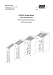
DIGIVEX Single Motion (DSM) User Manual
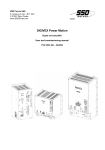
DIGIVEX Power Motion (DPM) User Manual
DIGIVEX Multi Motion (DMM) User Manual
DIGIVEX Motion - CANopen
DIGIVEX Motion - Profibus
PME-DIGIVEX Motion Adjustment Manual
DIGIVEX Motion Directory of Variables
DIGIVEX Motion Programming
DIGIVEX Motion - Cam Function
PME Tool kit User and Commissioning Manual
CANopen - CAN Bus Access via CIM03
CANopen - Remote control using PDO messages
"Block Positioning" Application Software
"Fly shear linear cutting" software application
"Rotary blade cutting" software application
(DSM)
(DPM)
(DMM)
PVD3515
PVD3522
PVD3523
PVD3518
PVD3554
PVD3516
PVD3527
PVD3517
PVD3538
PVD3528
PVD3533
PVD3543
PVD3519
PVD3531
PVD3532
1. GENERAL POINTS
"Block Positioning" software is a predefined application program for positioner drive control with
24V logic orders from a plc or manual switches. This software is only for DIGIVEX Motion with
CAN open communication interface
It can operate in either of two modes:
• Manual and teach mode:
Motion can be controlled with push-buttons
• Automatic Mode
The different movements and processing routines are defined in advance and
stored in "blocks" numbered 1-63. To initiate block execution, just select the block
number by a combination of logic inputs and then validate the selection with the
"start" input. Once the block has been executed, the drive switches the
"end_of_block" output state, indicating the block has been completed.
The blocks perform the following functions:
• absolute or relative motion
• tab positioning controlled by an interrupt input
• message display on the µVision terminal
• value entry via the µVision terminal
• ancillary functions:
♦ motor braking control
♦ origin setting
3
PVD 3519 GB 11/2003
DIGIVEX MOTION - "BLOCK POSITIONING" application software
2. COMMISSIONING STAGES
2.1 Wiring the mains supply, motor and resolver
Wiring information is given in the relevant DIGIVEX MOTION User Manual (DSM, DPM or DMM).
2.2 Wiring the drive logic inputs and outputs
Wiring information is given in the relevant DIGIVEX MOTION User Manual (DSM, DPM or DMM).
See Section 3.1 of this Manual for how to assign functions to inputs and outputs.
2.3 Connecting a PC with the CRS232 or CIM03 module
A PC is required for specifying the drive parameters and programming the drive. The PC is to be
connected to the drive via either a CRS232 module or a CIM03 module. These modules convert
the PC's RS232 link into a CAN link so connecting the PC to the CAN network. For further
information see the DIGIVEX MOTION - µVision - CRS232 - CAN –DAD05 (PVD 3518 Manual).
2.4 Energising the auxiliary power supply
The control section of the drive is energised and a connection with the PC can be established.
The motor is not powered up.
4
PVD 3519 GB 11/2003
DIGIVEX MOTION - "BLOCK POSITIONING" application software
2.5 Loading the drive parameters and settings
Follow the instructions in the PME - DIGIVEX MOTION (PVD 3516) Setting and Adjustment Manual which
explains the various parameter setting options (choice of operating mode, motor, etc.) and servo-control
adjustment.
The following options must be validated for this application program to work:
• enable program execution (Operating Mode environment, Options tab):
• ⌧ Enable program execution upon energizing
• ⌧ Wait for power-up before crossing PROG0 #START address
• enable torque (Operating Mode environment, Options tab):
⌧ Enable torque upon energizing
• Enable motion (Operating Mode environment, Options tab):
⌧ Enable motion upon energizing
• drive mode = position control (Operating Mode environment, Options tab):
⌧ Position control
• Input In14 must not be assigned (Input / Output environment, Logic Input tab):
in14 not assigned
• Output out0 must be assigned to the "home_made" system variable (Input / Output environment, Logic
Output tab):
• Output out2 must be assigned to the "fault" system variable (Input / Output environment, Logic Output
tab):
If the drive has hard limit switches:
• validate these contacts (Operating Mode environment, Origin Setting tab):
⌧ Hard limits active
• assign inputs In11 and In12 to these contacts (Input / Output environment, Logic Input tab):
• in11
hardp_input
• in12
hardm_input
If an origin switch is used:
• validate the origin switch (Operating Mode environment, Origin Setting tab):
⌧ Origin switch acknowledged
• assign input In13 to the origin switch (Input / Output environment, Logic Input tab): in13 switch0_input
2.6 Loading the "block positioning" application program and
specifying parameters
See the instructions in Section 4 of this Manual. The application program is in the directory
"C:\Parvex\Pme\App_Parvex\Samples\Motion_Block\" and is named "block.bdm". To recopy in
"C:\Parvex\PME\App_User" The program must be edited with the program editor, the parameters specified
with the values and types of motion to be performed and then loaded into the drive. All these operations are
carried out with PME software.
2.7 Testing
Manual mode is a simple mode for checking whether the unit is operating correctly. See Section 3 of this
Manual on how to activate manual mode.
5
PVD 3519 GB 11/2003
DIGIVEX MOTION - "BLOCK POSITIONING" application software
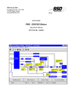
3. INSTRUCTIONS FOR USE
Once loaded the application program is ready for use. The program requests the block selection inputs be
scanned upon energising the auxiliary supply (option selected when specifying the drive parameters, see
Section 2.5).
The user has a "manual_sel" input for selecting either manual operation (motion controlled visually) or
automatic operation (blocks selected by combining logic inputs, inputs may be controlled by a plc).
3.1 Logic Inputs-Outputs over Sub-D Connector
3.1.1 Inputs
The logic inputs assignments are defined as follows:
Input
Name
in0
in1
in2
in3
in4
in5
in6
in7
in8
in9
in10
In11
In12
in13
in14
in15
fly_index
manual_p
manual_m
manual_sel
start
sel1
sel2
sel3
sel4
sel5
sel6
hardlimit_p
hardlimit_m
switch0
block_enable
teach_in
Function
position stop trigger
manual + direction
manual - direction
manual / automatic selection
selected block validation
block code weight 1
block code weight 2
block code weight 4
block code weight 8
block code weight 16
block code weight 32
+ electrical limit switch
- electrical limit switch
origin switch
block and motion enable
teach
Associated
Variable
hardp_input
hardm_input
switch0_input
Type
rising edge
state
state
state
pulse
state
state
state
state
state
state
state
state
state
state
edge
The "block_enable" input must be set to 1 for motion and block selection to be possible:
• In manual mode, setting this input to 0 inhibits acknowledgement of "manual_p" and
"manual_m" inputs and stops current motion (with deceleration ramp). Motion can only be
resumed if this input goes back to 1.
• In automatic mode, setting this input to 0 stops current motion (with deceleration ramp) and
the current block is considered to have been completed. The "start" input is no longer
acknowledged and no new block can be selected.
3.1.2 Definition of levels
Level 1 :
Level 0 :
Command or logic state corresponding to a potential close to the 24 V supply voltage.
Command or logic state corresponding to an open circuit or potential close to 0V.
6
PVD 3519 GB 11/2003
DIGIVEX MOTION - "BLOCK POSITIONING" application software
3.1.3 Outputs
Logic outputs are assigned in a fixed way:
Output
Name
Function
out0
home_made
Origin set info
out1
end_of_block
Block execution completed info
out2
fault
out3
-
Unused
out4
-
Unused
out5
-
Unused
out6
-
Unused
out7
-
Unused
Associated Variable
home_made
Drive fault info
fault
A "home_made" output tells the user whether the origin has been set. This output is set to 1 when
the origin has been successfully set. It is set to 0 on energising the appliance and at the start of
the origin setting cycle.
The "end_of_block" output, when at 1, indicates that no block and no motion is currently being
executed.
The "fault" output switches to 1 to indicate a fault with the drive (see the list of faults in the relevant
DIGIVEX MOTION Drive Manual (DSM, DPM or DMM)).
3.2 Manual and teach mode operation
Manual operation is selected if the "manual_sel" input is at 1:
• Maintaining state 1 on the "manual_p" input moves the axis in the positive direction.
• Maintaining state 1 on the "manual_m" input moves the axis in the negative
direction.
• Maintaining state 1 or 0 on both "manual_m" and "manual_p" inputs stops motion
(deceleration ramp).
• The "end_of_block" output is set to 0 when a manual displacement is underway and
is set to 1 otherwise.
• Motion stops when the system reaches an electrical or software limit switch
(stoppage with deceleration ramp). Only manual operation away from the limit
switch is then authorized.
• Setting the "block_enable" input to 0 inhibits acknowledgement of "manual_p" and
"manual_m" inputs and halts current motion (with deceleration ramp). The
"end_of_block" output is set to 1 when all movement has come to a halt. The
"manual_p" and "manual_m" inputs are then only acknowledged if this input is set
to 1 again.
7
PVD 3519 GB 11/2003
DIGIVEX MOTION - "BLOCK POSITIONING" application software
LOGIC CHART
manual_sel
manual_p
manual_m
end_of_block
Speed
TEACH
Teach mode is activated by setting input In15 to 1. It is valid in manual mode only. This functionality allows
64 absolute positions to be stored for subsequent re-use in motion blocks in automatic mode (blocks 14 62).
A rising edge on input In15 "teach_in" stores the absolute position of the axis. So the position can be
precisely read and stored it is recommended that the axis be at rest at the moment input In15 is activated.
The axis position is stored in a user variable ud, depending on the block number selected (inputs sel1 sel6) when input In15 is set to 1:
• ud0 for block 0
• ud1 for block 1
• .....
• ud63 for block 63
The ud variable may then be assigned to the uf7 variables of motion blocks 14-62 (see Section 4.6 of these
instructions):
%PROG14
; *** motion block 14 (absolute or relative movement) ***
;
ub0 = 1
; 1 = absolute 0 = relative
uf6 = 100
; speed to be used (in Units/s)
uf7 = ud14
; distance (in Units)
RETURN
%ENDPROG
8
PVD 3519 GB 11/2003
DIGIVEX MOTION - "BLOCK POSITIONING" application software
3.3 Automatic Operation
Automatic operation is selected if the "manual_sel" input is at 0:
• The user must select a block (numbered 0-63) with the "sel1" to "sel6" inputs (see table
below).
• The user must then validate the selection by a rising edge on the "start" input (it is
acceptable for the code and start to rise at the same time). The "end_of_block" output
then switches to 0 (indicating the block is being executed and the start signal can fall
again). It is best to test the "end_of_block" output state before asking for a new block.
This output must be at 1 when a new block is to be selected. If the "start" input switches
to 1 (rising edge) when a block is being executed, the block request is ignored.
• When execution of the block is completed, the "end_of_block" output switches back to 1
(indicating execution of the block is complete, and the device waits for a new block to be
selected).
• When the system reaches an electrical or software limit switch, block execution is halted
and cannot be resumed and current motion stops (with deceleration ramp, the stop
position becomes the current position). Only movement away from the limit switch is then
authorized.
• A 0 state on the "block_enable" input inhibits acknowledgement of the "start" input (no
block can then be selected).
• During execution of the block with motion (blocks 3 and 14-63), if the "block_enable"
input switches to 0 then block execution is halted permanently (motion stop with
deceleration ramp, and the stop position becomes the current position). The
"end_of_block" output is reset to 1 when all motion has stopped completely.
The user can access the following functions by selecting the appropriate code:
Block
no.
0
1
2
3
4
…
9
10
11
12
13
14
...
62
63
sel 6
sel 5
sel 4
sel 3
sel 2
sel 1
0
0
0
0
0
…
0
0
0
0
0
0
...
1
1
0
0
0
0
0
…
0
0
0
0
0
0
...
1
1
0
0
0
0
0
…
1
1
1
1
1
1
...
1
1
0
0
0
0
1
…
0
0
0
1
1
1
...
1
1
0
0
1
1
0
…
0
1
1
0
0
1
...
1
1
0
1
0
1
0
…
1
0
1
0
1
0
...
0
1
Function
No effect - block unused
Open brake
Close brake
Origin setting
Display operator message
Display operator message
Display operator message
Conversational (variable uf0)
Conversational (variable uf1)
Conversational (variable uf2)
Conversational (variable uf3)
Absolute or relative motion
Absolute or relative motion
Absolute or relative motion
Position stop triggered by fly_index input
N.B. Once the "end_of_block" disappears (state 0) it is best to zero reset the "start" input. Before
motion ends, the block number may also be changed to prepare the next block as it will only be
validated by a rising edge on the "start" input.
9
PVD 3519 GB 11/2003
DIGIVEX MOTION - "BLOCK POSITIONING" application software
4. INITIALISING BLOCKS
To set the application parameters, the user must complete the following internal variables:
Block Type
Internal Variables Used
initialise variables uf0 - uf3
µVision terminal address
page number for display
acceleration value
speed of displacement in manual mode
message script
Operator message display
•
•
•
•
•
•
Conversational
• question script
Displacement
•
•
•
•
•
General initialisation
(program 9999)
Position stop
type of displacement (absolute or relative)
speed of displacement
position to be reached or relative displacement value
speed of displacement
stop distance (the sign indicates the direction of motion)
4.1 Common Values (PROG99)
The header of the "motion_block.bdm" program is the general variable initialisation program. The
parameters of this program 99 must be specified using the application values. The numerical
values must be replaced by the desired values. However, the program must not be modified by
deleting lines or changing the names of variables.
%PROG99
; ∗∗∗ default values for user variables ∗∗∗
;
uf0 = 0
; default value of uf0 (keyboard value
uf1 = 0
; default value of uf1 (keyboard value
uf2 = 0
; default value of uf2 (keyboard value
uf3 = 0
; default value of uf3 (keyboard value
;
ui0 = 32
; keyboard address
ui1 = 1
; page number for display
;
uf4=100
; acceleration value in Units/s²
uf5=100
; speed for manual mode in Units/s
;
RETURN
%ENDPROG
10
PVD 3519 GB 11/2003
of
of
of
of
block
block
block
block
10)
11)
12)
13)
DIGIVEX MOTION - "BLOCK POSITIONING" application software
4.2 Brake Controls - Blocks 1 & 2
There is no parameter specification for the brake control blocks. There is therefore no %PROG1
or %PROG2.
If the brake is declared as being controlled by the program, and the system is in automatic mode
("manual_sel" input at 0), then:
Block 1 controls brake opening.
Block 2 control brake closure.
N.B. For both blocks, the "end_of_block" output is maintained at 0 for 50 ms (so any external plc
has time to acknowledge it).
If the brake is declared open in the parameters when powered up, these two instructions are
unused.
LOGIC CHART :
Select block
1 or 2
start
end_of_block
3 - 6 ms
50 ms
11
PVD 3519 GB 11/2003
DIGIVEX MOTION - "BLOCK POSITIONING" application software
4.3 Origin Setting - Block 3
There is no parameter specification for block 3 which controls origin setting. There is therefore no
%PROG3. The origin setting options are defined in the drive parameters (PME DIGIVEX MOTION
Setting and Adjustment Manual).
To request origin setting, block 3 must be selected (automatic mode, therefore "manual_sel" = 0).
When origin setting is requested, "end_of_block" switches to 0. At the end of origin setting,
"end_of_block" switches back to 1 as does the "home_made" out0 output indicating the origin has
been set. The "home_made" output switches to 1 as soon as the origin is encountered while the
"end_of_block" output only switches back to 1 when the axis is stopped again. The switching time
delay between these two outputs is related to the braking time.
N.B. If origin setting is interrupted by "block_enable" = 0
When the "Block_enable" input switches to zero causes:
• stoppage with ramp
• after stopping, the "end_of_block" signal is reset to 1
• conversely, the "home_made" signal remains at 0
• no action on the brake
To resume origin setting, block 3 must be selected again
LOGIC CHART :
Select Block 3
start
home_made
end_of_block
3 - 6 ms
12
PVD 3519 GB 11/2003
DIGIVEX MOTION - "BLOCK POSITIONING" application software
4.4 Transmitting Messages to the µVision Terminal - Blocks
4-9
Blocks 4-9 are used to send a message to the µVision terminal. Parameters can be specified for
each block defining the messages to be displayed on line 1 and line 2. The message displayed is
the script in "Quotation marks".
This script can contain a maximum of 15 characters. The remainder of the program must not be
modified.
%PROG4
; ∗∗∗ operator message block4 ∗∗∗
;
uc0 = "text block4 L1"
;message to be displayed on line 1
uc1 = "text block4 L2"
;message to be displayed on line 2
RETURN
%ENDPROG
………………..
………………..
%PROG9
; ∗∗∗ operator message block9 ∗∗∗
;
uc0 = "text block9 L1"
;message to be displayed on line 1
uc1 = "text block9 L2"
;message to be displayed on line 2
RETURN
%ENDPROG
N.B. For blocks 4-9, the "end_of_block" output is maintained at 0 for 50 ms (so any external plc
has time to acknowledge it).
LOGIC CHART
Select Block
4-9
start
end_of_block
3 - 6 ms
50 ms
13
PVD 3519 GB 11/2003
DIGIVEX MOTION - "BLOCK POSITIONING" application software
4.5 Entering Values via the Terminal - Blocks 10-13
Blocks 10-13 are for:
•
•
•
Asking a question via the µVision terminal and entering a numerical value
Testing the numerical value entered by the operator
Using the value entered as a position or speed in the motion blocks
Block call-up routine:
•
•
•
•
•
•
•
When the block is called, the drive sends the message defined in the block
(maximum 15 characters, script in " Quotation marks " in the program) to the
µVision terminal screen
The "end_of_block" output switches to 0
The operator must then key in a numerical value and validate it with the ENTER key
When the value reaches the drive, the drive records the datum in a variable
(variable uf0 for block 10, uf1 for block 11, uf2 for block 12 and uf3 for block 13)
The drive then tests the variable and checks that it is contained within the interval
defined by uf8 (upper limit) and uf9 (lower limit)
If the test fails, the "ERROR" message is displayed on the µVision terminal for 1 s
and then the drive sends the message again and awaits a response
If the test is successful, the "end_of_block" output switches back to 1
%PROG10
; ∗∗∗ operator message block10
;
uc0 = "text block10 L1"
uf8 = 0
uf9 = 0
RETURN
%ENDPROG
………………..
………………..
%PROG13
; ∗∗∗ operator message block13
;
uc0 = "text block13 L1"
uf8 = 0
uf9 = 0
RETURN
%ENDPROG
, response stored as uf0 ∗∗∗
;message to be displayed on line 1
;upper limit of keyboard value
;lower limit of keyboard value
, response stored as uf3 ∗∗∗
;message to be displayed on line 1
;upper limit of keyboard value
;mower limit of keyboard value
14
PVD 3519 GB 11/2003
DIGIVEX MOTION - "BLOCK POSITIONING" application software
4.6 Displacement Blocks - Blocks 14-62
Blocks 14 to 62 are positioning blocks. For each block used, the user simply introduces:
• the mode of displacement (absolute or relative),
• the displacement value,
• the displacement speed.
N.B. Values assigned to speed or displacement may be:
• either numerical values,
• or variables uf0, uf1, uf2 or uf3 entered through blocks 10-13.
• a variable ud0 - ud63 entered in teach mode for an absolute movement
%PROG14
; ∗∗∗ motion block 14 (absolute or relative movement)
;
ub0 = 1
; 1 = absolute 0 = relative
uf6 = 100
; speed to be used
uf7 = 12.5
; distance
RETURN
%ENDPROG
∗∗∗
……….
……….
%PROG62
; ∗∗∗ motion block 62 (absolute or relative movement)
;
ub0 = 0
; 1 = absolute 0 = relative
uf6 = uf2
; speed to be used
uf7 = uf3
; distance
RETURN
%ENDPROG
15
PVD 3519 GB 11/2003
∗∗∗
DIGIVEX MOTION - "BLOCK POSITIONING" application software
DISPLACEMENT BLOCK LOGIC CHART
Select block
14-62
start
end_of_block
3 - 6 ms
Speed
INTERRUPTING A DISPLACEMENT BLOCK
If a block is interrupted by the "block_enable" input switching to 0:
• braking occurs (with ramp),
• after stopping, the "end_of_block" signal is set to 1 again,
• there is no action on the brake.
The interrupted block is considered to have been completed.
Several possibilities arise:
• If the block was programmed in absolute mode, the "block_enable" signal can be
set to 1 again and the block reactivated by the "start" input to complete the
trajectory,
• If the block was programmed in relative mode, the interrupted block cannot be
completed (If the block were to be reactivated, the system would perform the full
relative displacement).
16
PVD 3519 GB 11/2003
DIGIVEX MOTION - "BLOCK POSITIONING" application software
4.7 "Position Stop" Block - Block 63
•
•
•
Block 63 is a "position stop" type block (stoppage at a programmed distance after sensor
action on an interrupt input).
This block starts motion at the speed declared by uf6. The direction of motion is given by the
displacement sign uf7.
When the "fly_index" input is triggered (a rising edge on this input is acknowledged), motion
stops at a distance uf7 after the input signal (stoppage in the direction of motion).
%PROG63
; ∗∗∗ motion block 63 (stop after interrupt)
;
uf6 = 100
; speed to be used
uf7 = 0
; distance
RETURN
%ENDPROG
∗∗∗
Caution: if distance uf7 is too short (shorter than the braking distance required for speed uf6), the
motion will overshoot and back up before stopping at distance uf7. If this must be avoided, select
2
uf7 > ½ (uf6) /(acceleration).
LOGIC CHART (rising edge of in0)
Select block
63
start
fly_index
end_of_block
Programmed distance uf7
3 - 6 ms
Speed
N.B. If "block_enable" switches to 0 during execution of the block, movement stops, the block is
discontinued and "end_of_block" switches to 1.
17
PVD 3519 GB 11/2003
DIGIVEX MOTION - "BLOCK POSITIONING" application software
5. BRAKE CONTROL
The 24 V brake is energised or de-energised:
• By the external 24 V "BRAKE SUPPLY" of terminal block B1. This 24 V supply is
controlled by the external plc.
• Once the 24 V is established, an internal relay is used to close or open the brake
depending on:
♦ the brake control blocks,
♦ the drive operating mode
(Caution! This relay is not available on DMM drives).
N.B. General brake operation is explained in the PME-DIGIVEX MOTION Setting and Adjustment
Manual.
6. FAULT RESETTING
The "fault" output at 1 indicates a drive fault (see the relevant DIGIVEX MOTION Drive Manual
(DSM, DPM or DMM)).
In this event:
• The current block is interrupted and motion stopped (the interrupted block is
considered to have been completed).
• The fault diagnosis is indicated on the 7-segment drive display.
• For serious faults the "OK" relay is opened.
Resetting the device by switching the RESET input to 1 (on the front panel of the drive, terminal 12 of terminal block B5):
• clears electrical or thermal faults (if the causes of the faults have been remedied),
• closes the "OK" relay allowing power to be restored to the drive (if the causes of the
faults have been remedied),
• resets the "fault" output to 0.
18
PVD 3519 GB 11/2003