1
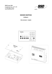
DIGIVEX Servoamplifier Terminal
CONTENTS
1.
GENERAL
2
2.
DESCRIPTION
2
3.
CONNECTION
3
4.
PARAMETER ACCESS CODE
3
5.
USE
4
5.1 PARAMETER GROUPS, DISPLAY AND MODIFICATION
5.1.1
DETAILED DESCRIPTION OF GROUPS
5.1.1.1
HAND TERMINAL
5.1.1.2
APPLICATION NAME
5.1.1.3
FAULT
5.1.1.4
SECURITY CODE
5.1.1.5
STATUS (GROUP N° 1)
5.1.1.6
GENERAL DRIVE (GROUP N° 2)
5.1.1.7
INPUT SELECTION (GROUP N° 3)
5.1.1.8
ANALOG OUTPUT SELECTION (GROUP N° 4)
5.1.1.9
SPEED CONTROL SELECTION (GROUP N° 5)
5.1.1.10
ENCODER STATUS (GROUP N° 6)
5.1.1.11
FEED FORWARD COMPENSATION (GROUP N° 7)
5.1.1.12
FUNCTION GENERATOR (GROUP N° 8)
5.1.1.13
MOTOR (GROUP N° 9)
5.1.1.14
RESOLVER SETTING* (GROUP N°0)
6. TRANSFERRING PARAMETERS BETWEEN
SERVOAMPLIFIERS:
4
5
5
5
5
6
6
6
7
7
8
9
9
10
11
11
12
Characteristics and dimensions subject to change without notice.
YOUR LOCAL CORRESPONDENT
SSD Parvex SAS
8 Avenue du Lac / B.P 249 / F-21007 Dijon
Cedex
Tél. : +33 (0)3 80 42 41 40 / Fax : +33 (0)3 80
42 41 23
www.SSDdrives.com
1
PVD 3491 GB 01/2003
DIGIVEX Servoamplifier Terminal
1. GENERAL
This document is for use in conjunction with the DIGIVEX PC SOFTWARE User's Manual PVD
3483 which gives detailed descriptions of the parameters, inputs/outputs, predictors, etc. referred
to here.
2. DESCRIPTION
DIGIVEX TERMINAL
AP502V01
SHIFT
VALUE
Í
GROUP
COPY
Î
PARAM
ENTER
DISPLAY SCREEN: Gives message readouts on 2 lines of 16 characters.
SHIFT KEY: Provides extra information
(possible causes, times) for fault-finding.
« VALUE » KEY : Modifies the value of the
parameter selected. Right arrow (Î) to
increase, left arrow (Í) to decrease.
COPY KEY: Uploads or downloads a
complete set of parameters. The terminal
can store a single parameter file (on
EEPROM).
PARAM KEY: Selects the required
parameter from a group. Right arrow (Î) to
scroll forwards, left arrow (Í) to scroll
backwards through the parameters of a
group.
ENTER
KEY:
Acknowledges
new
parameter after modification. For most
parameters, if ENTER is not used the
previous value is restored when passing to
the next parameter.
GROUP KEY: Parameters are arranged in
separate groups. The Group Key is used for
switching from one group to the next, even
while working on a parameter.
2
PVD 3491 GB 01/2003
DIGIVEX Servoamplifier Terminal
Weight and dimensions (See Drawing FELX 305318 at the end of this document).
•
•
Dimensions: Length: 146 mm. Width: 90 mm. Depth: 26 mm (plus 3 mm for keys).
Mass: 0.3 kg
3. CONNECTION
By connecting the RS232 serial link cable incorporated in the terminal to the DIGIVEX's RS232
connector. The servoamplifier powers the unit.
• Cable: Extendible telephone type cable. Cable length at rest approximately 0.38 m. Stretched
length approximately 2 m (excluding connector).
4. PARAMETER ACCESS CODE
When setting the servoamplifier with DIGIVEX PC software or at the factory, access to
parameters can be restricted by a code.
This code cannot be created or modified via the terminal. If used, it must be keyed in each time
the unit is connected up to gain access to level 2.
Level 1: read only parameters, read input/output status, internal variables, motor characteristics,
etc.
•
•
•
•
Level 1, via the terminal, enables only:
limited gain variation,
limited speed variation for 1 volt,
offset adjustment,
global upload/download.
Level 2 authorises all the parameters to be modified.
If no code is used (00000000 by default), no reference to the code comes up on the terminal.
3
PVD 3491 GB 01/2003
DIGIVEX Servoamplifier Terminal
5. USE
The DIGIVEX servoamplifier terminal is first and foremost a maintenance tool. It allows the
following operations:
• Reading or slight modification of the parameters already introduced when initially set up.
• Servoamplifier status display and fault finding.
• Transfer of parameters from one servoamplifier to another when changing servoamplifiers.
5.1 PARAMETER
MODIFICATION
GROUPS,
DISPLAY
AND
Each group can be accessed via the GROUP key and most are assigned an order number.
The different parameter groups that can be accessed are:
• Status display and fault finding groups
♦ APPLICATION NAME
♦ SECURITY CODE: parameter protection
♦ FAULT : error diagnosis
♦ NUMBER 1 STATUS: actual status of logic inputs/outputs and internal variables
•
•
Parameter reading or modification groups
♦ No. 0 RESOLVER SETTING: resolver timing (depending on servoamplifier connected)
♦ No. 2 GENERAL DRIVE: general characteristics and access code
♦ No. 3 INPUT SELECTION: forcing of logic inputs and validation of external current
limitation
♦ No. 4 ANALOG OUTPUT SELECTION: assignment of internal variables to the two
analog outputs
♦ No. 5 SPEED CONTROL SELECTION: speed loop parameters
♦ No. 6 ENCODER STATUS: resolution and encoder emulation zero mark
♦ No. 7 FEED FORWARD COMPENSATION: predictor setting
♦ No. 8 FUNCTION GENERATOR: stimuli validation
♦ No. 9 MOTOR: motor characteristics
Groups associated with options:
See the specific documentation for the relevant option.
4
PVD 3491 GB 01/2003
DIGIVEX Servoamplifier Terminal
5.1.1 DETAILED DESCRIPTION OF GROUPS
5.1.1.1 HAND TERMINAL
Terminal welcome message upon connection to the axis and display of the software version of the
axis connected (e.g. AP502V01).
5.1.1.2 APPLICATION NAME
Name of the application introduced by the DIGIVEX-PC software.
5.1.1.3 FAULT
Access to display of the last 30 faults recorded in the axis connected. The fault type and total
operating time are displayed.
The fault number locates the fault displayed in the list of faults stored: e.g. fault 30 = most recent
faults, fault 1 = oldest fault.
Faults displayed:
• maximum motor current
• dI/dt
• maximum supply current POWER
• resolver fault
• maximum speed
• excessive ambient temperature
• excessive radiator temperature
• excessive motor temperature
• If(t)
• I²f(t)
• excessive bus voltage
• customisation board fault
• axis-spindle cohesion
• microprocessor fault
OVERCURRENT,
SHORT CIRCUIT,
POWER,
RESOLVER FAULT
OVERSPEED,
AMBIENT OVERTEMP,
FIN OVERTEMP,
MOTOR OVERTEMP,
I AVERAGE FAULT,
I RMS FAULT.
BUS OVERVOLTAGE
EEPROM FAULT
SPINDLE BIT DEF.
CPU FAULT
Any fault appearing on the connected axis is immediately displayed on the terminal.
For faults related to options, see the relevant user manuals.
This function can be accessed without the security code.
5
PVD 3491 GB 01/2003
DIGIVEX Servoamplifier Terminal
5.1.1.4 SECURITY CODE
Parameter protection.
Security code validation is displayed on the terminal if it is different from 0000 0000 (see §4).
5.1.1.5 STATUS (GROUP N° 1)
status of logic input/output :
TORQUE, CW, CCW, external current reduction, FLAG SPEED 1, FLAG SPEED 2.
Move from one parameter to the next with the PARAM key and the left (Í) and right (Î) keys.
Display the following variable values:
• speed setpoint
RPM,
• speed feedback
RPM,
• current setpoint
A,
• position value
DEG,
• bus voltage
V,
• radiator temperature
°C.
Values displayed are not filtered.
Values cannot be modified with the VALUE+ and VALUE- keys.
Accessible without the security code.
5.1.1.6 GENERAL DRIVE (GROUP N° 2)
Move from one parameter to the next with the PARAM key and the left (Í) and right (Î) keys.
Display the application's main characteristics:
• DIGIVEX rating,
• DIGIVEX serial number,
• Motor type,
• Encoder emulation resolution
PPR,
• Total operating time
H,
• Operating time without torque
H.
Values cannot be modified with the VALUE+ and VALUE- keys.
6
PVD 3491 GB 01/2003
DIGIVEX Servoamplifier Terminal
5.1.1.7 INPUT SELECTION (GROUP N° 3)
Move from one parameter to the next with the PARAM key and the left (Í) and right (Î) keys.
Logic command set-up:
TORQUE, CW, CCW, current limitation
TORQUE
CW
CCW
SPEED REF *
ACCESSIBLE VALUE
INTERN 1, INTERN 0, EXTERN
INTERN 1, INTERN 0, EXTERN
INTERN 1, INTERN 0, EXTERN
INTERN 1, INTERN 0, EXTERN
ACCESSIBLE VALUE
Current limitation
YES, NO
* depending on the servoamplifier connected.
CODE
YES
YES
YES
YES
CODE
YES
Press ENTER to validate.
5.1.1.8 ANALOG OUTPUT SELECTION (GROUP N° 4)
Move from one parameter to the next with the PARAM key and the left (Í) and right (Î) keys.
Setting-up the two analog outputs: choice of variable to be displayed + choice of scale.
The accessible variables are:
• Speed setpoint
RPM,
• Speed feedback
RPM,
• Bus voltage
V,
• Current control
A,
• Position
DEG.
• Power
W*
Can be modified with security code.
Variables accessible via the PC and not described above are displayed under the name PC
DEFINED. Scaling is then dimensionless.
* Depending on servoamplifier connected.
7
PVD 3491 GB 01/2003
DIGIVEX Servoamplifier Terminal
5.1.1.9 SPEED CONTROL SELECTION (GROUP N° 5)
Move from one parameter to the next with the PARAM key and the left (Í) and right (Î) keys.
Display the parameters relating to the speed loop:
• Maximum speed,
• Offset,
• Choice of corrector type,
• Speed gradient 1,
• Speed gradient 2*,
• Proportional gain,
• Integral gain,
• Low-pass filter cut-out frequency,
• Current limitation value,
• Overcurrent strategy,
• SPEED FLAG1,
• SPEED FLAG2.
• Logic output functions*
* Depending on the servoamplifier connected
Max speed
Current limitation
SPEED FLAG1
SPEED FLAG2
MIN VALUE
100
0
38.2
SPEED FLAG1
MAX VALUE
VMOTOR
CVI
SPEED FLAG2
Max speed
VARIATION
4.8
CVI / 327.68
4.8
4.8
UNIT
RPM
A
RPM
RPM
CODE
YES
YES
YES
YES
MIN VALUE
MAX VALUE
VARIATION
UNIT
34.7.10-6 GV
1.05 if < 1720 ,
4.2 if not
4,2
6.392.10-3 CVI
0.1
5
mV
RPM/V
SANS
CODE
YES
+/- 10%
RPM/V
mA/RPM
Hz
Hz
+/- 10%
0.7 - 1.4
0.7 - 1.4
0.7 0 1.4
offset
Speed gradient 1
-0.01 * 10 * GV
10
0.01 * 10 * GV
20000
Speed gradient 2
gain
integral
Filter frequency
10
6.392.10-3
0.1
20
20000
209.45
150
800
8
PVD 3491 GB 01/2003
DIGIVEX Servoamplifier Terminal
VMOTOR
VM
CVI
GV
=
=
=
=
motor speed,
maximum speed,
servoamplifier pulse current,
speed gradient.
Press ENTER to validate parameter.
Corrector type
Strategy for excessive
current
VALUE
P, PI, PII, current (with validation)
REDUCTION or STOP
CODE
YES
YES
Press ENTER to validate.
5.1.1.10 ENCODER STATUS (GROUP N° 6)
Move from one parameter to the next with the PARAM key and the left (Í) and right (Î) keys.
Encoder emulation option set-up:
• Resolution,
• Zero mark placement.
MIN
VALUE
Resolution 1
MAX
VALUE
16384
VARIATION
1
UNIT
points per
revolution
CODE
YES
Not accessible without security code.
Values can only be changed when torque is off.
Press ENTER to validate choices.
5.1.1.11 FEED FORWARD COMPENSATION (GROUP N° 7)
Move from one parameter to the next with the PARAM key and the left (Í) and right (Î) keys.
Compensation set-up:
• gravity,
• static,
• threshold,
• dynamic,
• acceleration.
9
PVD 3491 GB 01/2003
DIGIVEX Servoamplifier Terminal
GRAVITY
STATIC
THRESHOLD
VISCOUS
DYNAMIC
MIN VALUE
-0.35*CVI
0
34.7.10-6 * GV
00
0.01
CVI
GV
pulse servoamplifier rating
speed gradient
=
=
MAX VALUE
0.35*CVI
0.25*CVI
1.01 *GV
100*CVI/ GV
10
VARIATION
0.01*CVI
0.005*CVI
34.7.10-6* GV
5 * CVI / GV
0.005
UNIT
A
A
RPM
A/1000RPM
s
CODE
YES
YES
YES
YES
YES
5.1.1.12 FUNCTION GENERATOR (GROUP N° 8)
Move from one parameter to the next with the PARAM key and the left (Í) and right (Î) keys.
Stimuli selection and set-up:
• signal type,
• amplitude,
• offset,
• frequency,
• activate or deactivate.
MIN VALUE
Amplitude 0
Offset
-(VM - amplitude)
Frequency 0.0611
VM
GV
=
=
Signal type
Activation
MAX VALUE
VM - offset
VM - amplitude
500.8
VARIATION
34.7.10-5GV
34.7.10-5GV
0.0611
maximum speed
speed gradient.
ACCESSIBLE VALUE
SINUS or SQUARE
ON or OFF
CODE
YES
YES
Press ENTER to validate.
10
PVD 3491 GB 01/2003
UNIT
RPM
RPM
Hz
WITHOUT
CODE
YES
YES
YES
DIGIVEX Servoamplifier Terminal
5.1.1.13 MOTOR (GROUP N° 9)
Move from one parameter to the next with the PARAM key and the left (Í) and right (Î) keys.
Access to motor characteristics:
• motor type (not modifiable),
• maximum speed,
• rated current,
• Rpp,
• Lpp,
• Ke,
• Brake choice,
• Thermal choice.
Maximum speed
Rated current
Rpp
Lpp
Ke
CVI
=
MIN
VALUE
100
0
1.628.10-3
76.29.10-3
5
MAX
VALUE
100000
CVI
53.33
2499
2900
VARIATION
4.8
0.01CVI
1.628.10-3
76.29.10-3
0.08856 if Ke < 1000
0.9741 if not
UNIT
RPM
A
Ohms
mH
V
CODE
YES
YES
YES
YES
YES
pulse servoamplifier rating.
Values can only be modified when " torque is off ".
Press ENTER to validate.
Brake choice
Thermal choice
ACCESSIBLE VALUE
ON or OFF
ON or OFF
CODE
YES
YES
Press ENTER to validate.
5.1.1.14 RESOLVER SETTING* (GROUP N°0)
Accessible only with security code.
Displays polarisation current and electrical timing angle.
ATTENTION: Resolvers mounted on H-series motors are factory set. Consequently the procedure
described above below is only to be used exceptionally and exclusively after agreement with
PARVEX S.A.
The operator turns the resolver stator mechanically to a position close to 0 degrees: standard
setting X0.
* Depending on servoamplifier connected.
11
PVD 3491 GB 01/2003
DIGIVEX Servoamplifier Terminal
6. TRANSFERRING PARAMETERS BETWEEN
SERVOAMPLIFIERS:
This operation may be useful for transferring all parameters from one servoamplifier to another
(e.g. when swapping servoamplifiers).
Accessible from any parameter via the COPY key.
SERVOAMPLIFIER TO TERMINAL:
The transfer may be made with torque off or on.
The terminal advises the user it is going to overwrite a stored parameter file. All the parameters on
the customisation board are copied to the terminal, including the security code.
TERMINAL TO SERVOAMPLIFIER:
Three conditions must be met:
• rating of parameter file to be transferred = rating of receiving axis,
• receiving axis with compatible security code:
♦ axis with no security code. In this case the security code of the axis becomes that of the
transferred parameter file.
♦ axis with security code. The security code of the parameter file to be transferred must be
the same (it is impossible to transfer the parameter file without a code in this case).
• axis automatically switches torque off during transfer.
12
PVD 3491 GB 01/2003
DIGIVEX Servoamplifier Terminal
13
PVD 3491 GB 01/2003