1
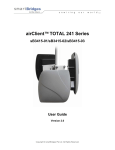
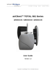
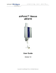
s m a r t Bridges
to the future ...
airBridge Series Wireless Ethernet Client
Quick Install Guide
Installing the airBridge Series
airBridge series is a wireless client which can be used to connect any PC with Ethernet
port to a network / PC / Internet wirelessly. It is a simple plug and play device needing no
configuration. It operates at 2.4 GHz ISM band. Using an external directional antennas
for the airBridge outdoor can provide range of upto 32 Kilometers. It provides data rates
upto 11Mbps and encryption capability of 64 bits or 128 bits. It can interface with any
wireless LAN device complying with 802.11b specifications.
Currently there are 3 models in the airBridge series
1.
airBridge - Indoor wireless ethernet client with a 2.2 dBi antenna
2.
airBridge Outdoor - Outdoor wireless ethernet client device.
3.
airBridge TOTAL - Outdoor wireless ethernet client device integrated with a 13 dBi / 9
dBi* flat panel antenna. Now with new enhancements like Surge Protection and an
external N connector for an external antenna option.
Note:
* 13dBi integrated antenna comply to FCC standards. 9dBi integrated antenna comply to ETSI
standards.
Revision 1.7
Page 1 of 16
Contents of Package
airBridge
airBridge Outdoor
airBridge TOTAL
l
airBridge Unit
l
airBridge Outdoor Unit
l
airBridge TOTAL Unit
l
powerShot
l
powerShot
l
powerShot
l
AC Adapter
l
AC Adapter
l
AC Adapter
l
External 2.2 dBi Antenna
l
l
l
Ethernet Cable 1.5 meter
long
Pole Mounting Kit: U
Bracket, Nuts, Washers
Pole Mounting Kit: U
Bracket, Nuts, Washers
l
airBridge Setup Software
and User Manual CD
Wall Mounting Kit: Wall
plugs, Screws
l
l
Wall Mounting Kit: Wall
plugs, Screws
l
Quick Install Guide
airBridge Setup Software
and User Manual CD
l
l
airBridge Setup Software
and User Manual CD
l
Quick Install Guide
l
Quick Install Guide
l
Coax Seal
l
Earthing Tag for Grounding
the TOTAL
l
Coax Seal
Hardware Installation
for airBridge
l
Insert the Power Jack into the powerShot & connect the AC Adapter to the mains wall
outlet.
l
Connect the RJ45 Ethernet cable from powerShot to PC.
l
Connect the powerShot with airBridge.
l
Verify that the PWR & ETH LEDs are ON.
l
airBridge with its Factory Default Settings will associate with the nearby Access Point
by itself. (indicated by steadyTxRx LED) airBridge is now ready for operation.
Ethernet port
Revision 1.7
Page 2 of 16
s m a r t Bridges
to the future ...
For airBridge Outdoor / TOTAL
Important note - Earthing Requirements:
Follow National Electric Code NEC 810-20 and NEC 810-21 for this installation.
Rooftop Installation
The airBridge TOTAL can be mounted on the rooftop with the directional antenna
pointing towards the Access Point. Connect a outdoor rated shielded CAT5 / CAT5e
ethernet cable which carries power and data signals to airBridge Outdoor / airBridge
TOTAL. Other end of the cable is connected to the PC through the powerShot. The AC
adapter connected to the powerShot provides the power to the airBridge Outdoor /
airBridge TOTAL.
Preparation of the Site:
The wireless waves propagate in straight lines. So it is essential that the antennas in the
airBridge Outdoor / airBridge TOTAL and Access Point are in line of sight without any
obstruction. Select the most appropriate place on the roof which will provide a direct view
to the Access Point. Secure a 1.5 inch steel pipe vertically and insure that it cannot come
Access Point
RJ45 Ethernet Port
AC/DC Adapter
to airBridge Outdoor /
airBridge TOTAL
Revision 1.7
powerShot
Page 3 of 16
Mounting the airBridge Outdoor
Attach the airBridge Outdoor unit with the U bolts to the steel pipe. Make sure to
tighten both top and bottom mounting plates to the pipe with U bolts, nuts and
spring washers. Tighten the nuts so that the airBridge does not rotate on the
pipe. The mounting should be such that the antenna socket, LED's, Ethernet
Cable outlet etc face downward. The airBridge Outdoor is weather proof box
made to NEMA 4 specs. There are no user adjustable parts inside and it is
recommended that the unit is used in the same way it is shipped.
Mounting the Antenna:
Follow the mounting instructions provided by the antenna manufacturer and mount
the antenna on the steel pipe. Antenna should be mounted on the same pipe as
the airBridge Outdoor and positioned above it. The height of the antenna and
direction should be in the direction of the Access Point. The antenna socket of
the airBridge Outdoor and the antenna input have to be connected by an RG 8
N Male to N Male cable. Use the Coax Seal to seal the N Connector after fixing RG 8
Male cable. Prevent rain water entering the RF cable.
Outdoor
Revision 1.7
Page 4 of 16
s m a r t Bridges
to the future ...
Mounting the airBridge TOTAL
Fix the Bracket arm of the airBridge TOTAL unit with the 2pcs of U bolts to the mast.
Make sure to tighten both top and bottom U bolts, with nuts and spring washers. Tighten
the nuts so that the Bracket arm does not rotate on the mast. Use the internal external
Toothed washer between cabinet bracket and mounting arm. Use the internal toothed
washer with the nut to ensure that the TOTAL is tightly held in place.
The airBridge TOTAL has a high gain in-built directional antenna. Depending on the
required signal polarity, use the correct fin for Vertical / Horizontal polarization. Please
note that the vertical polarity is indicated on the backside of the device. Mount the unit on
the Mounting arm with the 1/4" bolt, spring washer and nut and tighten.
Adjust the azimuth of the airBridge TOTAL unit by rotating the Mounting arm attached to
the mast. Adjust the elevation / tilt angle of the airBridge TOTAL unit by rotating it around
the fin.
Use the correct azimuth and the elevation angle to point the airBridge TOTAL unit
towards the remote transmission tower.
Use the Antenna alignment mode in the simpleMonitor software to maximize the received
signal strength for the unit.
Mounting Arm
airBridge TOTAL
U-bolt fixing pipe
to Mounting Arm
Cable Tie
RJ45 Cable
Weather proof
Connector
Mounting Arm
Revision 1.7
Page 5 of 16
Grounding:
The internal ground of the TOTAL is brought out to an earthing stud at the bottom side of
the unit. Please crimp a 10 AWG wire to the earth tag and secure the earth tag onto the
earthing stud tightly with the M6 nut provided. Ensure that the other end of the 10 AWG
wire is grounded to the earth at the power ground of the premises.
Note: Grounding has to be done before mounting the TOTAL on wall / pole.
Cabling:
The airBridge TOTAL is terminated into a weatherproof RJ45 female connector for
outdoor use. Refer to the cable and connector installation instructions supplied with the
weatherproof connector for more information. The user can connect required length of
suitable ethernet cable to connect the airBridge TOTAL to the user's PC / Network. RJ45
male connector is provided inside weatherproof connector for use with the ethernet cable
from PC. We strongly recommend an outdoor rated shielded CAT5 / CAT5e cable to
connect the TOTAL to the PC inside premises.
Note: The BBDN cable connected to TOTAL has minimum bending rating 50mm. Sharper
bends will break the ground foil inside the cable.
Mounting the External Antenna for TOTAL:
Follow the mounting instructions provided by the antenna manufacturer and mount the
antenna on the steel pipe. Antenna should be mounted on the same pipe as the
airBridge TOTAL and positioned above it. The height of the antenna and direction should
be in the direction of the Access Point. The antenna socket of the airBridge TOTAL and
the antenna input have to be connected by an RG 8 N Male to N Male cable.
Wall mounting:
Use the supplied wall mounting plugs with screws and washers to mount the mounting
arm directly on the wall instead of using U bolts to mount on a mast.
RJ45 to Network / PC
to airBridge / airBridge Outdoor /
airBridge TOTAL
AC Adapter
powerShot
Cross Coupler switch
RJ45 Cable
SB2820
Revision 1.7
Page 6 of 16
s m a r t Bridges
to the future ...
PC, powerShot Connection:
The powerShot has two input points and an outlet. One input is DC jack adaptable to the
AC adapter output. This is a flying lead connector as shown in the diagram. Other input is
RJ 45 Ethernet male connector with a short cable as shown in the diagram. This can be
directly plugged into the ethernet signal port of the LAN or PC. There is an LED indicator
on the injector indicating power is ON. The output port is RJ45 socket with DC power and
is part of the casing itself. A standard RJ 45 male to male cable is provided as standard
accessory to power injector to airBridge. When the user wants to use a longer cable to
position airBridge at a distance, the user is advised to use a standard RJ 45 cable (CAT
5 cable) with 8 wires.
Cross coupler switch in SB2820 powerShot selects straight or crosssed ethernet
connection.
For cable lengths in excess of 50 meters it is recommended that the AC adapter should
be of 18 Volt type. Normally 12 Volt AC adapter is provided with the airBridge.
Note:
Restore Default button at the bottom side of the powerShot should be used to restore the device
back to factory / WISP defaults.
Restore Default button
Cross Coupler switch
Revision 1.7
Page 7 of 16
Software Installation
System Requirements
Computer with Windows 98/ME/NT/2000/XP supporting ethernet connectivity
Installing airBridge setup Software:
Please insert the Setup Software CD into the CD-ROM drive of your PC. The CD will run
automatically. If it doesn't autorun, please browse the CD and double click on index.htm.
l
Select the appropriate product from the drop-down list and click the Go button.
l
Click on the Setup File link. You should see the File Download dialog box.
l
Select Open or Run this program from its current location to start the setup.
l
The setup will install all the necessary files in the "C:\Program
Files\smartBridges\airBridge" directory.
l
The installation will create the shortcuts in your Program Menu at
smartBridges\airBridge for easy accessibility of Setup software.
o
Firmware upgrade utility allows upgrading of firmware.
o
o
simpleMonitor allows configuration of the airBridge.
User Guide shows the User Guide in HTML form.
Web Register opens the product registration of airBridge on smartBridges
website.
Known Issues with the Software, Firmware and Hardware.
o
Uninstall the Setup Software.
o
o
l
After Installing please restart the PC if asked.
Uninstalling airBridge Setup Software:
Click on the shortcut "Start > Programs > smartBridges > airBridge > Uninstall
airBridge" and it will uninstall the setup software from your PC.
Note:
airBridge, airBridge Outdoor and airBridge TOTAL can be configured using the same
software which is referred to as airBridge.
Revision 1.7
Page 8 of 16
s m a r t Bridges
to the future ...
Configuring the airBridge
For Windows 98 / ME / NT / 2000 / XP
The factory default parameters for the airBridge are
l
IP Address
:
192.168.0.22
l
Subnet Mask
:
255.255.255.0
l
Gateway
:
0.0.0.0
l
Administrator Password
:
public (case sensitive)
l
User Password
:
public (case sensitive)
l
Authentication Type
:
open key
l
WEP Keys
:
None
l
WEP Algorithm
:
Disabled
l
ESSID
:
Any
l
BSSID
:
000000000000
l
Preamble
:
Long
l
Operating Channel
:
Country Specific
l
Regulatory Domain
:
Country Specific
l
Configuration Port
:
Both
l
Primary DHCP Port
:
Wireless
Revision 1.7
Page 9 of 16
Login
l
Connect the airBridge to the Network Card's RJ45 connector using the given cable.
l
Make sure the power to the airBridge is ON.
l
Start the simpleMonitor by clicking on the shortcut: Start > Programs >
smartBridges > airBridge > airBridge simpleMonitor.
l
Click on Search button.
l
If the login parameters are correct, you will get the message:
"Successfully read the airBridge Configuration".
In case of a successful connection to the airBridge, simpleMonitor acknowledges by
enabling all the tabs.
Revision 1.7
Page 10 of 16
s m a r t Bridges
to the future ...
Security
l
By default encryption is disabled which means the communication is not secure. In
case you want to have a secure communication, ensure that the WEP encryption
setting for airBridge are the same as that of Access Point.
l
To set the encryption keys click on security tab:
o
Select the Encryption Key(64Bit/128Bit).
o
Enter Hex data.
o
Select the desired key to be used(Default Key).
o
Save the WEP Keys....
o
You will get a pop up window with the message "WEP Encryption Keys Saved
Successfully".
Note:
Recommended format is HEX format. Incase other devices used along with smartbridges
products need only ASCII based encryption, please use the ASCII to HEX table. See
appendix A.
Revision 1.7
Page 11 of 16
Site Survey
l
l
l
l
l
Click on Site Survey tab:
o
Select Infrastructure Mode
o
Check Select From Available Access Point.
o
Double click on the desired Access Point.
o
You will see the message "Device is successfully Associated…"
Use antenna alignment tool while adjusting the antenna to get better link.
The RSSI values are shown in dBm in the dialog box as per the internal formula. If
you want specific values to be shown in there, please store them in the table and set
the option as "User Defined" from Advanced TAB.
The TxRx LED will be lighted after successful association.
If airBridge fails to associate, Please ensure that the WEP key settings for airBridge
as well as the desired Access Point are the same and airBridge is authorized to
associate with the desired Access Point.
Note:
Alternatively, if the desired access point does not appear in the available list the ESSID, BSSID,
Channel and the Preamble of a particular access point can be entered manually if you want to
associate with it. This can be done by unchecking the 'Select from Available Access Points'. Please
make sure that you are not using ESSID as "Any" in ADHOC Mode. This is especially reserved for
infrastructure Mode only.
Revision 1.7
Page 12 of 16
s m a r t Bridges
to the future ...
Advanced
l
Change default values of Regulatory Domain & operational channel:
1.
Select appropriate Regulatory Domain from Drop Down List.
2.
Select appropriate Channel from the Channel Drop Down List, click on Set
Default Config button to change the default settings for Regulatory Domain
and Channel.
3.
Specify appropriate values for Fragmentation and RTS Threshold (refer to
user guide for more details).
4.
Select authentication type from drop down list.
5.
Select the appropriate port for getting the lease from the DHCP server and the
default gateway. Select either ethernet or wireless port.
6.
You can select both ethernet as well as wireless as configuration port. This will
enable device configuration from the LAN or wireless side.
7.
Specify DHCP TimeOut option. By enabling the DHCP Timeout airBridge will
search for DHCP Server for 1 min after boot-up (if DHCP is enabled in IP
Settings) and if it doesn't get the lease it will fall back to previously obtained IP
Address. If you want airBridge to search for DHCP Server till it obtains the
lease, disable this option. (This option is supported from F/W Ver 0.01.09
onwards).
8.
Click on set configuration button to save these parameters.
Transmission and Reception Antenna:
Allows the user to select between Antenna A and Antenna B for reception of signals.
Diversity options will select the Antenna with best possible signal reception sensitivity
(recommended) if additional antenna is connected.
airBridge Outdoor:
1. Antenna A - Internal Antenna (this is not used)
2. Antenna B - External Antenna
airBridge TOTAL:
1. Antenna A - Internal Antenna (here the 9dBi or 13dBi Antenna is used)
2. Antenna B - External Antenna (provision is made with N Type connector)
Authentication Type:
The authentication type defines configuration options for the sharing of wireless
networks to verify identity and access privileges of roaming wireless network
cards. Select Open System or Shared Key Authentication Type or Both:
Revision 1.7
Page 13 of 16
l
Open System: With this setting any station in the WLAN can associate with
an Access Point and receive and transmit data (null authentication).
This default setting allows a device, regardless of its WEP keys, to
authenticate and then attempt to communicate with another device. If the
bridge is using WEP and the other device is not, the other device can
authenticate with the bridge but cannot communicate.
l
Shared Key: With this setting only stations using a shared key encryption
identified by the Access Point are allowed to associate with it. The
bridge
sends an unencrypted challenge text string to any device attempting to
communicate with the bridge. The device requesting authentication encrypts
the challenge text and sends it back to the bridge. If the challenge text is
encrypted correctly, the bridge allows the requesting device to authenticate.
Both the unencrypted challenge and the encryption challenge can be
monitored, however, which leaves the bridge open to attack from an intruder
who guesses the WEP key by comparing the unencrypted and encrypted
text strings. Because of this weakness, Shared Key authentication can be
less secure than Open authentication.
l
Both: Open and Shared Key supported.
Note:
The Authentication type
must be the same on the
airBridge and on the
Access Point. All WEP
keys on the airBridge must
be the same as those on
the Access Point with
which the airBridge is
associated.
Important:
The default setting is
internal antenna (Antenna
A) shipping condition,
whenever an external
antenna is connected,
change the selection to
Antenna B.
Revision 1.7
Page 14 of 16
s m a r t Bridges
to the future ...
Dial-A-Power
This feature of airBridge allows the user to control the radio transmit power of the
airBridge from the simpleMonitor software. Make use of the user interface controls in this
Tab to adjust the radio transmit power. Dial a Power facility is available only if you login
as Administrator.
1. Select the antenna connected to airBridge from Antenna Type drop down list, if you
happen to select the Custom Antenna, please enter the Valid Gain. The limit is 1.0
dBi to 30.0 dBi.
2. Specify Cable Loss value in the Edit box. The limits for this value are min 0.5 dB,
max 10.0 dB.
3. Use slider control to adjust EIRP Output power from the airBridge. As you move the
slider pointer, observe that EIRP Output power is displayed in Effective output Power
Display.
4. The Effective Power is calculated as equal to airBridge output Power(dBm) - Cable
Loss(dB) + Antenna Gain(dBi).
5. Click Set Power button. This will change the radio transmit power of the airBridge
unit. A message will be displayed after successful completion of this operation.
Revision 1.7
Page 15 of 16
Restore Factory Default Settings
If you forget the critical settings like WEP or Administrator Password of the airBridge, you
can restore the airBridge to the Factory Default Settings as,
1. Make sure that the Power to the airBridge is ON. ( indicated by PWR LED )
2. Locate and Press the Restore Default button continuously. ( The Restore Default
button is located on the back of powerShot.)
3. The TxRx LED will dim its light intensity for few seconds.
4. Release the button after the TxRx LED restores back to its original bright intensity.
5. After restoring the Factory Default Settings, please configure the airBridge again.
Appendix A
ASCII to Hexadecimal Conversion Table
Operating Temperature Range
airBridge
airBridge Outdoor / TOTAL
Ingress Specification
:
:
:
0 °C ~ +50 °C
(+32 °F ~ +122 °F)
-40 °C ~ +65 °C
(-40 °F ~ +150 °F)
IP65 for airBridge Outdoor / TOTAL
Products and model numbers
sB2100
sB2110
sB2120
sB2125
airBridgeTM Indoor FCC and CE versions
airBridgeTM Outdoor FCC and CE versions
airBridgeTM TOTAL FCC version 13 dBi antenna
airBridgeTM TOTAL CE version 9 dBi antenna
Note:
Please refer to the User Guide found on the Setup CDROM for detailed and additional information.
For the latest Quick Install Guide and software updates, please visit our support webpage at
http://www.smartbridges.com/support/
Revision 1.7
Page 16 of 16