1
OPS-2000 User’s Guide
Advanced Use of Expert Objects
example file: sys.ops
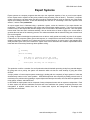
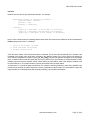
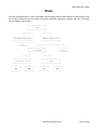
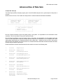
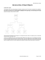
This example uses a set of expert objects to simulate a computer circuit. This circuit is composed of two multipliers,
an adder, and an output device. The adder and the multipliers each take two inputs. The output device only takes one
input. Each of the boxes in the below diagram corresponds to an expert object. The lines between the boxes
represent interobject communication channels.
+-------+
|output |
|device |
+-------+
|
+-------+
| adder |
|
+
|
+-------+
|
|
+----->-----+
+----<-----+
|
|
+-----------+
+-----------+
|multiplier |
|multiplier |
|
*
|
|
*
|
+-----------+
+-----------+
|
|
|
|
+>-+
+-<+
+>-+
+-<+
|
|
|
|
+-------+
+-------+
+-------+
+-------+
| input |
| input |
| input |
| input |
| one |
| two |
| three |
| four |
+-------+
+-------+
+-------+
+-------+
The input units feed input sets to the multipliers. The multipliers feed their results to the adder's inputs, and the adder
sends its results to the output device.
A feature of the receive statement's current implementation allows for this system to be run by changing environment
to that of the output-device's expert object, and then running it. The receive statement will cause demand-driven input
to each of the expert objects from the four input units to the output device. When the four input units stop producing
data, the multipliers will stop. Once the multipliers have stopped, the adder will stop which stops the output device.
www.siliconvalleyone.com
Page 51 of 56