1
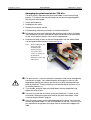
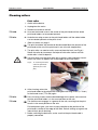
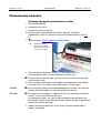
02/02 Rev. 2.14-01
USER MANUAL
Maintenance, Page 1
TTX x50/67x – Wildcats/Wildcats plus – S 45/65/95/105 – TDI/STDI/XXtreme
Maintenance
General information....................................... 2
Specialist servicing .................................... 2
Safety ........................................................ 2
Troubleshooting......................................... 2
Ordering spare parts.................................. 3
Cleaning........................................................ 4
Advice on cleaning .................................... 4
Cleaning agent .......................................... 4
Print head...................................................... 5
Cleaning the print head.............................. 5
Changing the print head of the TTX x50 /
TDI ............................................................ 7
Changing the print head of the TTX 67x .... 9
Cleaning rollers ........................................... 11
Print roller ................................................ 11
Cleaning the feed roller............................ 12
Photoelectric switches ................................. 13
Cleaning the punch photoelectric switch .. 13
Cleaning the material end photoelectric
switch ...................................................... 14
Cleaning the cutter ...................................... 15
TDI / XXtreme / STDI only ........................... 16
Cleaning the single-label intake roller ...... 16
Cleaning the short-tag option ................... 16
Cleaning rollers and axles ........................... 17
Index ........................................................... 18
02/02 Rev. 2.14-01
USER MANUAL
Maintenance, Page 2
TTX x50/67x – Wildcats/Wildcats plus – S 45/65/95/105 – TDI/STDI/XXtreme
General information
Specialist servicing
Regular and proper servicing is essential if the device is to be kept
permanently ready for use.
Servicing and repair work may only be carried out by suitably qualified
personnel. The safety, reliability and long life of the device depend on
proper servicing and repair.
Qualification
Damage caused by inexpert servicing, repair or maintenance will be
regarded as the fault of the originator.
For reliable servicing, maintenance, diagnosis and troubleshooting, please
contact your supplier, the next customer service center or other service
agents authorized by the manufacturer.
Manuf. service
Safety
CAUTION!
Servicing and repair work can lead to hazardous situations. Accidents can
be caused by mechanical or electrical action if the relevant safety advice
is not heeded!
– Disconnect the device before servicing, repair and maintenance!
– Isolate the device from the mains before opening the housing!
– Ensure the device is in a safe condition before restarting (refit all covers
etc.)!
– Take the utmost care when cleaning the cutter!
Troubleshooting
Status
Call service
If faults occur during operation, you must first analyze the status reports of
the device.
See under "Status reports".
If you are not authorized to diagnose and troubleshoot faults, call your
technician or the authorized service personnel. The service personnel will
have the documents and spare parts enabling them to carry out repair work
of the correct standard.
02/02 Rev. 2.14-01
USER MANUAL
Maintenance, Page 3
TTX x50/67x – Wildcats/Wildcats plus – S 45/65/95/105 – TDI/STDI/XXtreme
Ordering spare parts
Use only spare parts supplied by the manufacturer. The use of lower quality
non-OEM parts can lead to unnecessary problems.
To order, please supply the following information:
Order details
–
–
–
–
–
Type of device
Serial number of the device
Device equipment (fitted accessories)
Name and part number of the spare part
Number of parts required
02/02 Rev. 2.14-01
USER MANUAL
Maintenance, Page 4
TTX x50/67x – Wildcats/Wildcats plus – S 45/65/95/105 – TDI/STDI/XXtreme
Cleaning
Advice on cleaning
Intervals
Regular servicing and cleaning are essential to ensure reliable operation
and high performance. The servicing intervals depend on the following
conditions:
the operating and ambient conditions
the daily length of operation
the print medium
You must take particular care to clean the print head and feed roller
regularly of paper, glue and ink deposits.
Use the cleaning foil at the start of the foil roll! This will remove foil residues
from the print head that cannot be removed using cleaning spirit. This will
help to protect the print head against damage caused by overheating.
Cleaning agent
Contaminated part
Print head
Rubber rollers (e.g. print roller, feed
roller, brake roller)
Metal deflector axles or pipes
External parts
Cleaning agent
Cleaning spirit
Roller cleaner (order no. 97925)
Cleaning spirit, label solvent
Commercial neutral cleaners
Tab. 1: Recommended cleaning agents
Do not use any cleaning agents which could damage or destroy varnished
surfaces, lettering, the display, rating plates, electrical components etc.
Do not under any circumstances use cleaning agents that are abrasive or
dissolve plastic! Avoid the use of acidic and alkaline solutions.
02/02 Rev. 2.14-01
USER MANUAL
Maintenance, Page 5
TTX x50/67x – Wildcats/Wildcats plus – S 45/65/95/105 – TDI/STDI/XXtreme
Print head
Cleaning the print head
1. Switch off the device.
2. Unplug from the mains.
3. Remove the material and foil.
The electrostatic charge of your body can damage the print head! You
should therefore discharge your body before touching the print head by
touching a radiator or other grounded object.
The print head does not need to be disconnected! Before undoing the
screws, mark the position of the print head on the axle if the print head is
not at the left stop position.
TTX x50:
4a. Unscrew the thumb screw (1) in the center of the print head until the whole
print head holder can be rotated upwards (see Fig. 1:).
1
Fig. 1: Cleaning the print head of the TTX x50/Wildcat: Undo thumb
screw (1), swivel the print head up and wipe off.
TTX 67x:
4b. Undo the two wing screws (2) on the print head holder until the whole
holder can be rotated upwards on the pinch shaft (see Fig. 2:).
2
2
Fig. 2:
Cleaning the print head of the TTX x67/Wildcat plus: Undo wing
screws (2), swivel the print head up and wipe off. (Fig.: Printer with
cutter option)
02/02 Rev. 2.14-01
USER MANUAL
Maintenance, Page 6
TTX x50/67x – Wildcats/Wildcats plus – S 45/65/95/105 – TDI/STDI/XXtreme
5. Wipe the print head using a dustless cloth and cleaning spirit.
Do not use any objects with sharp edges. Metal objects must never touch
the surface of the print head!
6. After cleaning, return the print head holder to the old position and tighten
the thumb screw and wing screws again.
TTX 67x:
Press the wing screws onto the beveled edge of the square axle to ensure
that the print head holder is in the exact position on the axle.
TTX x50:
The thumb screw engages in a groove on the axle, ensuring that the print
head is in the exact position on the axle.
For both printer types, you must also pay attention to the position of the
print head in relation to the edge of the label. Default setting: up against the
internal black plastic bushing.
7. Before switching the device on, make sure that the print head cable is
properly connected.
02/02 Rev. 2.14-01
USER MANUAL
Maintenance, Page 7
TTX x50/67x – Wildcats/Wildcats plus – S 45/65/95/105 – TDI/STDI/XXtreme
Changing the print head of the TTX x50 / TDI
To disassemble
1. Switch off the device.
2. Unplug from the mains.
3. Remove the material and foil.
4. Pull both plugs from the print head in a horizontal direction.
Do not pull the print head cable from the print head until at least 3 minutes
after the device has been switched off.
5. Undo the two hexagon socket screws (1) on the print head (2.5 mm
hexagon socket screw key).
2
1
1
Fig. 3: Disassembling the print head of the TTX x50/Wildcat: Undo hexagon
socket screws (1), loosen thumb screw (2). Remove the print head.
6. Unscrew the thumb screw (2) in the center of the print head until the whole
print head holder can be rotated upwards (see Fig. 1:).
7. Carefully extract the print head.
Printer with attached cutter: Make sure that the underside of the print head
does not touch any metal parts.
The electrostatic charge of your body can damage the print head! You
should therefore discharge your body before touching the print head by
touching a radiator or other grounded object.
To assemble
8. To assemble the print head, place it on the two pins of the print head
holder, which is rotated upwards (see Fig. 4:).
You must first note the resistance of the print head (this is shown on the
print head). When placing the print head on the print head holder, make
sure that the print head is lying flat.
02/02 Rev. 2.14-01
USER MANUAL
Maintenance, Page 8
TTX x50/67x – Wildcats/Wildcats plus – S 45/65/95/105 – TDI/STDI/XXtreme
Fig. 4: Fitting the print head (3):
the pins (4) hold it in
position.
4
4
3
9. Rotate the print head and print head holder anticlockwise back onto the
print drum. Keep the print head and print head holder together while doing
so.
Do not touch the underneath of the print head or the plug!
10. Use the two hexagon socket screws to screw the print head back onto the
print head holder.
11. After screwing in, return the print head to its previous position and tighten
the thumb screw.
The thumb screw engages in a groove on the axle, ensuring that the print
head is in the exact position on the axle.
You must also pay attention to the position of the print head in relation to
the edge of the label. Default setting: up against the internal black plastic
bushing.
12. Attach the cable to the print head.
13. The resistance of the print head must be entered in the Parameters menu
after the printer has been switched on.
See "SYSP/HRES" parameter under "Information Printouts and
Parameters".
The print head can be damaged if an incorrect resistance is entered!
14. Production tolerances on the print head may make it necessary to push the
print head in or against the direction of printing. This is done by slightly
turning the two grub screws on the front of the print head bracket when the
fixing screws have been loosened (using the supplied tool). The optimal
setting must be determined by test prints.
See under "Adjusting the print head position" in the "Servicing the print
module" section of the Service Manual.
Settings on the print head should only be performed by trained service
engineers!
02/02 Rev. 2.14-01
USER MANUAL
Maintenance, Page 9
TTX x50/67x – Wildcats/Wildcats plus – S 45/65/95/105 – TDI/STDI/XXtreme
Changing the print head of the TTX 67x
The print head is adjusted to the print head holder in the manufacturing
process. This means that the print head can only be exchanged together
with the print head holder.
1. Switch off the device.
2. Unplug from the mains.
3. Remove the material and foil.
4. Pull both plugs from the print head in a horizontal direction.
Do not pull the print head cable from the print head until at least 3 minutes
after the device has been switched off. Mark the position of the print head
on the axle if the print head is not at the left stop position.
6. Undo the two wing screws on the print head holder until the whole holder
can be removed from the pinch shaft (see Fig. 5:).
Fig. 5:
Disassembling the print
head of the TTX
x67/Wildcat plus:
Remove the plug,
unscrew the wing
screws (1) and remove
the print head.
(Illustration: device with
cutter option)
1
The print head is a sensitive electronic component and can be damaged by
electrostatic charges. You should therefore discharge the static on your
body before coming into contact with the print head by touching the base
plate of the printer. The print head must not be touched on the print rail (2)
or the plug contacts (1).
8. To assemble, bring the new print head holder into the old position and
tighten the wing screws.
You must first note the resistance of the print head (this is shown on the
print head). When placing the print head on the print head holder, make
sure that the print head is lying flat.
Press the wing screws onto the beveled edge of the square axle to ensure
that the print head holder is in the exact position on the axle. You must also
pay attention to the position of the print head in relation to the edge of the
label.
02/02 Rev. 2.14-01
USER MANUAL
Maintenance, Page 10
TTX x50/67x – Wildcats/Wildcats plus – S 45/65/95/105 – TDI/STDI/XXtreme
Default setting: up against the internal black plastic bushing.
9. Attach the print head cable to the print head again.
10. After starting up again, the resistance of the print head must be entered via
the "SYSTEM PARAMETERS/Head resistance" parameter.
The print head can be damaged if an incorrect resistance is entered!
Read more about this under "Exchanging the print head" in the "Servicing
the print module" section of the Service Manual.
02/02 Rev. 2.14-01
USER MANUAL
Maintenance, Page 11
TTX x50/67x – Wildcats/Wildcats plus – S 45/65/95/105 – TDI/STDI/XXtreme
Cleaning rollers
Print roller
1. Switch off the device.
2. Unplug from the mains.
3. Remove the material and foil.
TTX x50:
4a. Unscrew the thumb screw in the center of the print head until the whole
print head holder can be rotated upwards.
TTX 67x:
4b. Undo the two wing screws on the print head holder until the whole holder
can be rotated upwards on the pinch shaft.
Refer to section on page 5.
The print head does not need to be disconnected! Mark the position of the
print head on the axle if the print head is not at the left stop position.
5. The print roller can now be easily accessed from the front (see Fig. 6:).
Rotate the roller by increments and wipe off with roller cleaner until the
whole roller is free of deposits.
You must only clean the print roller with a dustless cloth and roller cleaner.
Never use knives or objects with sharp edges to clean the rollers!
Fig. 6: To clean the print roller,
rotate the print head
upwards (here: Lion
plus)
6. After cleaning, return the
print head holder to the old position and tighten the wing screws (TTX x67)
or the thumb screw (TTX x50) again.
TTX 67x:
Press the wing screws onto the beveled edge of the square axle to ensure
that the print head holder is in the exact position on the axle.
TTX x50:
The thumb screw engages in a groove on the axle, ensuring that the print
head is in the exact position on the axle.
For both printer types, you must also pay attention to the position of the
print head in relation to the edge of the label. Default setting: up against the
internal black plastic bushing.
7. Before switching the device on, make sure that the print head cable is
properly connected.
02/02 Rev. 2.14-01
USER MANUAL
Maintenance, Page 12
TTX x50/67x – Wildcats/Wildcats plus – S 45/65/95/105 – TDI/STDI/XXtreme
Cleaning the feed roller
The feed roller and plastic rollers should also be cleaned from time to time.
1. Disassemble the print head.
Refer to section Print head on page 9.
2. Rotate the feed roller by increments and wipe off with roller cleaner (see
Fig. 7:) until the whole roller is free of deposits.
Push the front material guide (1) and pinch rollers (2) to the side to give
better access to the roller.
Fig. 7: To clean the feed roller,
disassemble the print head and
push the material guide (1) and
pinch rollers (2) to the side.
2
1
6. After cleaning, return the print head holder to the old position and tighten
the wing screws (TTX x67) or the thumb screw (TTX x50) again.
TTX 67x:
Press the wing screws onto the beveled edge of the square axle to ensure
that the print head holder is in the exact position on the axle.
TTX x50:
The thumb screw engages in a groove on the axle, ensuring that the print
head is in the exact position on the axle.
For both printer types, you must also pay attention to the position of the
print head in relation to the edge of the label. Default setting: up against the
internal black plastic bushing.
7. Before switching the device on, make sure that the print head cable is
properly connected.
02/02 Rev. 2.14-01
USER MANUAL
Maintenance, Page 13
TTX x50/67x – Wildcats/Wildcats plus – S 45/65/95/105 – TDI/STDI/XXtreme
Photoelectric switches
Cleaning the punch photoelectric switch
1. Switch off the device.
2. Unplug from the mains.
3. Remove the material and foil.
4. Loosen the print head holder and rotate it upwards. The punch
photoelectric switch can now be easily accessed from the front (see Fig.
8:).
Refer to section Cleaning theprint head on page 5.
Fig. 8: Print head rotated
upwards. The punch
photoelectric switch (1)
is easily accessible.
1
5. Clean the punch photoelectric switch (1) with compressed air
(canned compressed air can be ordered as an accessory).
If there is heavy contamination, you must also clean it with cleaning spirit
and a dustless cloth.
6. After cleaning, return the print head holder to the old position and tighten
the wing screws (TTX x67) or the thumb screw (TTX x50) again.
TTX 67x:
Press the wing screws onto the beveled edge of the square axle to ensure
that the print head holder is in the exact position on the axle.
TTX x50:
The thumb screw engages in a groove on the axle, ensuring that the print
head is in the exact position on the axle.
For both printer types, you must also pay attention to the position of the
print head in relation to the edge of the label. Default setting: up against the
internal black plastic bushing.
7. Before switching the device on, make sure that the print head cable is
properly connected.
02/02 Rev. 2.14-01
USER MANUAL
Maintenance, Page 14
TTX x50/67x – Wildcats/Wildcats plus – S 45/65/95/105 – TDI/STDI/XXtreme
Cleaning the material end photoelectric switch
The material end photoelectric switch (1) is located on the internal red
material guide of the print module. The photoelectric switch must be
cleaned of material and dust residues at regular intervals. The cleaning
intervals will depend on the material used.
Fig. 9: Position of the material
end photoelectric switch
(1).
1
Clean the material end photoelectric switch (1) with compressed air
(canned compressed air can be ordered as an accessory).
If there is heavy contamination, you must also clean it with cleaning spirit
and a dustless cloth.
02/02 Rev. 2.14-01
USER MANUAL
Maintenance, Page 15
TTX x50/67x – Wildcats/Wildcats plus – S 45/65/95/105 – TDI/STDI/XXtreme
Cleaning the cutter
(Only with attached cutter option)
CAUTION!
Danger of cuts to hands and fingers!
– The utmost care must be taken when cleaning the cutters!
– Do not touch the blades with unprotected hands!
If processing self-adhesive material, glue residues must be removed at
regular intervals to ensure that the material is cut and runs perfectly. Paper
residues and glue can lead to malfunctions.
Use lint-free cloths and cleaning spirit to clean. Under no circumstances
should you work on the cutter blades with hard metal objects. Even the
slightest invisible damage to the blades can have a considerable
detrimental effect on cutting performance.
1. Switch the device off and unplug from the mains.
2. Remove the material and foil.
3. Remove glue residues from the top and bottom cutter. You may need to
swivel the cutter slightly to get access to the whole cutting edge.
02/02 Rev. 2.14-01
USER MANUAL
Maintenance, Page 16
TTX x50/67x – Wildcats/Wildcats plus – S 45/65/95/105 – TDI/STDI/XXtreme
TDI / XXtreme / STDI only
Cleaning the single-label intake roller
1. Switch off the device.
2. Unplug from the mains.
3. Clean the intake roller on the lifting table using a dustless cloth and roller
cleaner.
Cleaning the intake roller has a considerable effect on the accuracy of
printing and the transport reliability of the device. It is therefore essential
that cleaning is carried out at regular intervals (at least 2x daily).
Separating edge
The separating edge and the ball bearings should also be cleaned from
time to time.
The performance of the printer, and particularly that of the print head, can
be improved generally by keeping the print area free of contamination of
any kind.
Cleaning the short-tag option
(only TDI/STDI/XXTREME with short-tag option)
1. Switch off the device.
2. Unplug from the mains.
3. Clean the additional auxiliary feed axles regularly using a dustless cloth
and roller cleaner.
4. Clean the pinch rollers as well.
02/02 Rev. 2.14-01
USER MANUAL
Maintenance, Page 17
TTX x50/67x – Wildcats/Wildcats plus – S 45/65/95/105 – TDI/STDI/XXtreme
Cleaning rollers and axles
It is essential that the material and foil deflector points are cleaned regularly
of material and deposits. The cleaning intervals will depend on the material
used.
Clean material/foil deflector rollers and axles using cleaning spirit.
Contaminated surfaces considerably impair the feeding of material and foil
and thereby reduce the print quality that can be achieved.
02/02 Rev. 2.14-01
USER MANUAL
Maintenance, Page 18
TTX x50/67x – Wildcats/Wildcats plus – S 45/65/95/105 – TDI/STDI/XXtreme
Index
C
Cleaning ..................................................... 4
Cleaning agent ........................................... 4
Cleaning axles.......................................... 17
Cleaning deflector points .......................... 17
Cleaning rollers ........................................ 17
Cleaning spirit............................................. 4
Cleaning the material end photoelectric
switch ....................................................... 14
Cleaning the punch photoelectric switch... 13
G
General information .................................... 2
I
Ink deposits ................................................ 4
N
Neutral cleaners ......................................... 4
O
Ordering spare parts...................................3
P
Print head, changing...................................7
Print head, cleaning ....................................5
R
Resistance, print head ................................7
Roller cleaner .............................................4
S
Safety .........................................................2
Specialists ..................................................2
T
TDI intake roller, cleaning .........................16
TDI short-tag option, cleaning...................16
Troubleshooting..........................................2