1
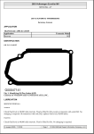
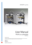
06/04 Rev. 3.00-02
SERVICE MANUAL
TTK
Servicing the Print Module
Construction of the print module .................... 2
Dismantling the print module ......................... 3
Draw unit........................................................ 5
How to completely dismantle the draw
unit ............................................................. 5
Dismantling the feed roller.......................... 6
Dismantling the pressure roller................... 7
Print unit......................................................... 8
Head-raising mechanism............................ 8
Dismantling the print unit.......................... 10
Print head contact adjustment.................. 11
Print head..................................................... 12
General information about the print head. 12
Setting the head voltage........................... 12
Setting further head parameters............... 12
Dismantling the print head........................ 13
Print head adjustment...................................14
Correcting the position in print direction....14
Correcting displacement ...........................15
Head aperture adjustment ........................15
Brake unit .....................................................19
Brake roller................................................19
Dismantling the brake unit ........................20
Contact axle ..............................................21
Gap photoelectric switch...........................22
Material end photoelectric switch..............23
Ribbon transport unit ....................................24
Ribbon unwinder .......................................24
Ribbon take-up..........................................25
Ribbon roller..............................................27
Adjusting the ribbon tautness....................28
Index.............................................................29
2
06/04 Rev. 3.00-02
SERVICE MANUAL
TTK
Construction of the print
module
The print module (ill.: dispenser version)
comprises the cast plate (1) with the
components mounted on top:
-
Servicing the Print Module
1
2
4
3
Ribbon roll-up mandrel (2)
Ribbon unwind mandrel (3)
Ribbon transport roller (4)
Draw unit (5)
Print unit (6)
Brake unit (7)
Head-raising mechanism (8)
Other components
5
8
7
9
¯ The print module can be completely
removed from the printer!
4
2
3
6
5
7
3
06/04 Rev. 3.00-02
SERVICE MANUAL
TTK
Servicing the Print Module
Dismantling the print
module
1
It is relatively simple to remove the cast plate
together with the components mounted on it.
Proceed as described below:
2
Tools
- Allan keys 2 mm, 2.5 mm and 3 mm
Disassembly/assembly
1. Remove the front and rear hoods.
2. Remove the front left and bottom right
housing.
P Instructions for removing the housing
parts can be found in the section
"Housing" in the chapter "Service /
General Information".
3. Pull the ribbon disc (1) off the ribbon rollup mandrel. Unscrew the Allan key
screw (2) first.
4. Detach all the cables which are
connected to the print module.
5. Remove the fastening screw (3) of the
draw unit support.
3
6. Remove the five fastening screws (4) of
the cast plate.
P Continued on the next page.
4
4
4
4
4
4
06/04 Rev. 3.00-02
SERVICE MANUAL
TTK
7. Carefully pull off the print module
towards the motor side.
Servicing the Print Module
1
¯ When assembling the print module, note
the position of the bouncer spring (2)
and the switch contact (3). The switch
contact must rest on the innermost cam
(4) of the eccentric axis.
P Information about the connections on
the boards can be found in the chapter
"Service - Boards".
2
4
3
5
06/04 Rev. 3.00-02
SERVICE MANUAL
TTK
Servicing the Print Module
Draw unit
The TTK/TEXXTILE holds the material taut
between the tension unit and the brake unit to
allow it to process very flexible textile material.
Essentially, the tension unit comprises of two
rollers which press down on each other, the
lower of which - the transport roller - is driven.
An eccentric axle provides the necessary
force on the pressure roller.
The following describes how to dismantle the
roller and the entire draw unit.
1
Tools
-----
Screwdriver
Socket wrenches, sizes 6 and 8
Grip ring pliers
Phillips screwdriver
2
3
How to completely dismantle the
draw unit
1. Disassemble the front and rear hoods,
and the front left and bottom right
housings.
P Instructions for removing the housing
parts can be found in the section
"Housing" in the chapter "Service /
General Information".
2. Remove the feed motor (1) and toothed
belt by unscrewing the three lock nuts
on the motor flange.
3. Remove the clamping ring (2). Pull off
the ratchet wheel (3) (e.g. by levering it
off with a strong screwdriver).
4
4. Unscrew the support leg of the draw unit
(4).
5
5. Remove the four fastening screws (5) of
the draw unit.
P Continued on the next page.
5
5
5
6
06/04 Rev. 3.00-02
SERVICE MANUAL
TTK
6. Carefully pull the draw unit (1) out of the
cast plate.
Servicing the Print Module
1
Dismantling the feed roller
1. Proceed as if removing the entire draw
unit until Step 3 (removing the ratchet
wheel).
2. Remove the locking screw (2).
3. Pull out the feed roller with the
bearings (3).
P Continued on the next page.
2
3
7
06/04 Rev. 3.00-02
SERVICE MANUAL
TTK
Dismantling the pressure roller
Servicing the Print Module
2
1. Dismantling the draw unit.
P See the section "Completely dismantling
the draw unit" for further details.
1
2. Remove the clamp/grip rings at both
ends of the eccentric axle (1).
3. Thread the eccentric axle out of its
bearing (2).
4. Clap up the support balancer (3) of the
pressure roller. Remove the lock screw
(4).
5. Thread the pressure roller with the
bearings out of the balancer (5).
3
4
5
8
06/04 Rev. 3.00-02
SERVICE MANUAL
TTK
Servicing the Print Module
Print unit
Essentially the print unit (1) comprises of the:
–
–
–
–
print head (2),
contact roller (3),
ribbon guide (4),
head-raising mechanism.
1
2
4
The following describes how to dismantle the
entire print unit.
Head-raising mechanism
3
If the ribbon economy function is activated,
the ribbon transport unit is halted over longer
print-free ranges, and at the same time the
print head is raised from the material. This
task is carried by the head-raising mechanism
(5), which is driven by a separate motor.
Tools
– Allan keys, 2.5 and 5 mm
– Screwdriver
5
Disassembly/assembly
1. Remove the front and rear hoods and
the front left housing.
P Instructions for removing the housing
parts can be found in the section
"Housing" in the chapter "Service /
General Information".
2. Remove the board base in order to
access the head-raising mechanism.
P See the section "Board base", chapter
"Service / General Information" for
further information
3. Unhitch the spring (6) from the lever (7).
P Continued on the next page.
6
7
9
06/04 Rev. 3.00-02
SERVICE MANUAL
TTK
Servicing the Print Module
4. Unscrew the grub screw (1).
5. Detach the head-raising mechanism
(2 and 3).
P Continued on the next page.
4
2
3
10
06/04 Rev. 3.00-02
SERVICE MANUAL
TTK
Servicing the Print Module
Dismantling the print unit
The rest of the print unit can be removed once
the head-raising mechanism has been
dismantled.
1
Tool
– Allan key, 5 mm
Disassembly/assembly
1. Dismantle the head-raising mechanism
as described in the previous section.
2. Remove the two fastening screws (1) –
one on each side of the partition.
3. Detach the print unit.
1
11
06/04 Rev. 3.00-02
SERVICE MANUAL
TTK
Servicing the Print Module
Print head contact adjustment
The initial tension in the tension spring (1) and
the position of the adjustment knob (2)
determine the extent of the print head contact
(if it is not in the ribbon economy position).
2
3
Tools
– Spring balance 0 to 50 N
(part no. 93665)
– Fork spanner SW 7
– Coupling
(part no. 96140)
Adjustment
4
1. Remove the rear hood.
P Instructions for removing the housing
parts can be found in the section
"Housing" in the chapter "Service /
General Information".
5
6
2. Set the adjustment knob (1) to the
minimum contact pressure (3).
3. Turn the sliding block on the head motor
until the contact arm of the head-raising
mechanism is recessed into the groove
of the sliding block ( = print head is in
the depressed position).
4. Screw the coupling onto the bolts (4).
5. Unscrew the fastening nut (5).
6. Attach the spring balance to the
coupling and pull on it until the spring
balance shows 9 N.
7. At the same time, tighten the fastening
nuts against the axis (6) and lock them.
1
12
06/04 Rev. 3.00-02
SERVICE MANUAL
TTK
Servicing the Print Module
Print head
¯ The print head (thermo head) is very sensitive, in particular to static
electricity. Static charges may not be allowed to make contact with the
thermo head when handling the component. This applies in particular when
it has been disassembled.
General information about the print head
Print head
A flat head type thermo head is used.
The thermo head is connected to the CPU mainboard by two connector
cables.
There are electronic and mechanical setting options.
Settings
Electronic settings:
– Supply voltage to the print head (HV99)
– Resistance value of the implemented print head (HRES)
Mechanical settings:
– Position of the print head
– Adjustment of the print head contact pressure
– Setting of the print head contact pressure (operator setting)
– Power supply (temperature) of the print head
– Adjustment of the head aperture
Setting the head voltage
¯ A falsely set maximum supply voltage can destroy the thermal bar!
1. In on-line mode press the buttons FEED+CUT(NEXT).
Display: HVxx (xx = value between 00 and 99)
2. Set the value xx to 99 by pressing the feed button.
3. Use the potentiometer R25 on the stepper board to set the head voltage.
Measure the head voltage at test point CN29.
P For details about the value of the head voltage as well as for the position of
the setting elements on the board, see subject section "Service - Boards".
Setting further head parameters
P For details about adjusting the print head temperature while printing, see
chapter "Info Printouts and Parameters", parameter HVxx.
P For details about setting the temperature reduction with increasing print
head temperature, see chapter "Info Printouts and Parameters", parameter
HEAT.
P For details about setting the head resistance when changing the thermo
head, see chapter "Info Printouts and Parameters", parameter HRES.
13
06/04 Rev. 3.00-02
SERVICE MANUAL
TTK
Servicing the Print Module
Dismantling the print head
¯ When removing or replacing the print head (1), ensure there is potential
equalisation between the operator's hand, the print head and the device.
¯ Please note that damage cannot be detected immediately, but that in some
cases it only occurs after a lengthy runtime!
¯ The following jobs may only be carried out when the device is not
connected to the power supply. Switch off the device and pull out the mains
plug !
Tool
– Allan key, 2.5 mm
Disassembly/assembly
4
1. Remove the front hood.
4
P Instructions for removing the housing
parts can be found in the section
"Housing" in the chapter "Service /
General Information".
1
2. The print head can be accessed more
easily if you remove the print roller (2)
first.
Ô To do this, unscrew the thumb screw ()
and pull the print roller (3) out of its
mounting.
5
P Additional information about removing
the print roller can be found in the
section "Replacing the print roller" in the
chapter "Commissioning and
Operation".
3. Detach both connector cables from the
print head.
1
2
3
4. Unscrew the two print head fastening
screws (4).
5. Remove the print head from the print
head mounting (5) in a downward
motion (if you have already removed the
print roller) or towards the rear of the
printer.
¯ During assembly, press the print head
firmly on both sides onto the setting
screws (6) in the head mounting, and at
the same time tighten the fastening
screws (4).
4
6
14
06/04 Rev. 3.00-02
SERVICE MANUAL
TTK
Servicing the Print Module
Print head adjustment
When changing the thermo head it may be
necessary to make the following adjustments:
¯ If necessary, programme the head
resistance by adapting the parameter
HRES accordingly.
(Make a note of the head resistance
given on the print head before
assembly!)
¯ Check the print quality and the direction
of the printout.
•
Insufficient print density: for measures,
see the section "Position in print
direction".
•
Crooked printout: for measures, see the
section "Correcting displacement".
Correcting the position in print
direction
1. Set the print head supply voltage to
HV99. To do this, press the CUT+FEED
button in the on-line mode. Increase the
setting value to 99 by pressing the
FEED button. Exit the parameter menu
by pressing the CUT+FEED button.
2. In the parameter menu select
INFO/DOT1 and confirm by pressing the
ENTER button. The printer prints a dot
test pattern.
3. Check the print density. If the printout is
not of a solid black colour, the print head
is not making contact on the highest
point of the contact roller.
In this case, screw in both of the grub
screws (1) on the front of the head
mounting by approx. one turn. Repeat
steps 5 and 6 until the printout is a solid
black colour.
¯ The print density is decreased if the
grub screws have been tightened too
much. Loosen both screws to correct
this.
1
1
15
06/04 Rev. 3.00-02
SERVICE MANUAL
TTK
Servicing the Print Module
Correcting displacement
Check whether the edges of the printout are
parallel to the borders of the labels. This is
easier to check if the borders are as narrow as
possible. Proceed as follows:
1. Set the parameter PRTP/YPOS to 1 or 2
(test). This shifts the printout relative to
the edge of the label.
2. Start INFO/STA2.
3. Correct any displacement (1) using the
grub screws in the head mounting.
Example (ill.): tightening the screw (3),
unscrewing the screw (2).
1
2
3
Head aperture adjustment
The head aperture is adjusted on the headraising mechanism (4). The sliding block and
oscillator disc of the head motor (5) are not
easily visible; dismantled parts are therefore
used in the illustrations to demonstrate the
settings.
Nominal value
When switched on and with ribbon inserted,
the aperture between the thermo head and
feed axle should measure between 0.75 mm
and 1.00 mm.
If this is not the case, set the head aperture as
follows:
Setting:
1. Remove any material.
2. Insert some ribbon if you have not done
so already.
3. Printer reset: Press the
FEED+CUT(NEXT)+ON/OFF buttons.
Display:
(flashing)
INIT
While INIT is flashing, press the
ON/OFF button.
Display:
CODE
P Continued on the next page.
5
4
16
06/04 Rev. 3.00-02
SERVICE MANUAL
TTK
Servicing the Print Module
4. Press the following buttons one after the
other:
FEED
CUT
ON/OFF
ON/OFF
FEED
CUT
5. If ON is displayed, press the ON/OFF
button.
Display:
OFF
6. Press the FEED+CUT button.
Display:
INFO
7. Press the CUT button several times
until:
Display:
OTHR
8. Press the ON/OFF button.
Display:
DOWN
9. Press the CUT button several times
until:
Display:
1
HADJ
10. Press the ON/OFF button.
Display:
YES
2
11. Press the ENTER button:
Display:
H
12. Press the ENTER button again.
Display:
H
printer emits a tone.
13. Switch off the printer using the mains
switch !
14. Unscrew the screw (1) on the head
lever.
15. Unscrew the grub screw (2) on the
oscillator disc.
16. Turn the sliding block (3) into the print
position. The contact arm (4) must now
be in the groove of the sliding block (5).
3
5
6
4
17
06/04 Rev. 3.00-02
P Continued on the next page.
SERVICE MANUAL
TTK
Servicing the Print Module
18
06/04 Rev. 3.00-02
SERVICE MANUAL
TTK
Servicing the Print Module
17. Lay 0.1 mm thick material (6) between
the sliding block and the contact arm.
18. Press the contact arm (1) against the
sliding block and retighten the screw.
1
19. Switch on the printer. The printer should
still be in the HADJ mode (Hx).
20. Ensure that the notch of the oscillator
disc (1) is at its highest point (12
o'clock).
Turn the notch slowly in a clockwise
direction (viewpoint: standing in front of
the opened rear hood), until 0 (zero) is
shown on the display. This should occur
when the edge of the notch passes the
photoelectric switch (2).
Carefully retighten the grub screw of the
oscillator disc. (Do not overtighten
because otherwise the plastic thread will
be damaged.)
21. Press the ENTER button: The printer
has now been reset!
The head aperture should now be set
correctly.
2
19
06/04 Rev. 3.00-02
SERVICE MANUAL
TTK
Brake unit
Servicing the Print Module
5
–
–
–
–
4
2
The following major components of the brake
unit (1) are described in the following:
3
Brake roller (2)
Contact axle (3)
Material end photoelectric switch (4)
Gap photoelectric switch (5)
Brake roller
1
Tools
– Phillips screwdriver medium size
Disassembly / Assembly
1. Unscrew the locking screw (6). Turn the
plate (7) aside.
2. Pull out the brake roller (2).
3. Insert the new brake roller.
7
4. Fix the plate, so that the brake roller
cannot move in an axial direction.
6
2
20
06/04 Rev. 3.00-02
SERVICE MANUAL
TTK
Dismantling the brake unit
Servicing the Print Module
2
1. Proceed as described in the section
"Dismantling the brake roller".
2. Remove the grip ring (1) and the red
lever (2) by unhitching the tension spring
at the top of the lever.
1
3
3. Remove the two hexagonal screws (3).
4. Carefully pull out the brake unit (4).
Thread through the connector cable of
the photoelectric switches.
3
4
21
06/04 Rev. 3.00-02
SERVICE MANUAL
TTK
Servicing the Print Module
Contact axle
The contact pressure rollers (2) of the contact
axle (1) provide the necessary friction
between the brake roller and the material.
Remove the brake unit for service work and to
access the contact axle.
2
1
2
Tool
3
– Clamp ring pliers
Disassembly/assembly
1. Remove the front and rear hoods.
P Instructions for removing the housing
parts can be found in the section
"Housing" in the chapter "Service /
General Information".
2. Dismantle the brake unit.
P See the section "Dismantling the brake
unit" for instructions.
3. Remove the grip ring (3).
4. Thread the contact axle out of the side
guidings (4).
4
22
06/04 Rev. 3.00-02
SERVICE MANUAL
TTK
Servicing the Print Module
Gap photoelectric switch
The part shown here (ill. 1) is called a gap
photoelectric switch. The gap photoelectric
switch is fitted with a transparent sensor as
standard, but a reflecting sensor can also be
equipped as an option. The gap photoelectric
switch is removed from the brake unit after
this has been dismantled.
1
Tools
– Allan key 3mm
– Side-cutting pliers
Disassembly/assembly
1. Remove the front and rear hoods.
P Instructions for removing the housing
parts can be found in the section
"Housing" in the chapter "Service /
General Information".
2. Dismantle the brake unit.
P See the section "Dismantling the brake
unit" for instructions.
2
3. Unplug the connector cable of the gap
photoelectric switch from the stepper
board and thread it through the aperture
in the cast plate. Remove any cable
binders which may be present.
4. Remove the retaining screws (2) on the
two guide axles.
2
3
5. Pull out the guide axles (3).
6. Remove the screw (4) on the retaining
plate.
3
The gap photoelectric switch can now be
removed.
4
23
06/04 Rev. 3.00-02
SERVICE MANUAL
TTK
Servicing the Print Module
Material end photoelectric switch
1
The material end photoelectric switch is
integrated in the rear material guide (1). The
following description and the adjacent
illustrations refer to a dismantled brake unit –
the parts concerned are more visible here.
The material guide can, however – albeit more
difficultly – be removed without dismantling
the brake unit.
Tools
– Allan key size 2.5
– Grip ring pliers
2
Disassembly/assembly
3
1. Remove the front and rear hoods.
P Instructions for removing the housing
parts can be found in the section
"Housing" in the chapter "Service /
General Information".
2. Dismantle the brake unit.
P See the section "Dismantling the brake
unit" for instructions.
5
5
3. Unscrew the thumb screw of the front
material guide (2).
4
4. Unscrew the grub screw (3) on the
bottom of the rear material guide.
5. Push the grip ring (4) to the middle of
the axle.
5
6. Push the axle to one side against the
resistance of the clamping ring (5).
7. Pull the clamping ring and material
guide off the side which is now clear (6).
3. Unplug the connector cable of the gap
photoelectric switch from the stepper
board and thread it through the aperture
in the cast plate. Remove any cable
binders which may be present.
6
24
06/04 Rev. 3.00-02
SERVICE MANUAL
TTK
Servicing the Print Module
Ribbon transport unit
3
4
The following parts ensure that the ribbon is
transported evenly and without folds:
–
–
–
–
1
Ribbon unwinder (1)
Ribbon guide (2)
Ribbon roller (3)
Ribbon take-up (4)
The ribbon unwinder (1) and ribbon take-up
(4) are almost identical - the only difference
concerns a few parts on the motor side of the
print module. The unwinder is fitted with an
oscillator disc (for controlling the unwinding
process) and a brake disc. The take-up does
not have an oscillator disc, and the brake disc
is replaced by a pulley for the drive belt.
Tools
2
4
1
– Socket wrenches, sizes 7 and 8
– Allan key 2 mm
Ribbon unwinder
Disassembly/assembly
1. Remove the rear hood.
P Instructions for removing the housing
parts can be found in the section
"Housing" in the chapter "Service /
General Information".
2. Unscrew the nut (3). Counterhold the
threaded rod against the red hexagon
head.
4. Turn out the threaded rod on the red
hexagon head while holding on to the
cap (4).
P Continued on the next page.
4
3
25
06/04 Rev. 3.00-02
SERVICE MANUAL
TTK
Servicing the Print Module
4. Remove the cap, spacing ring, spring,
shims (1), oscillator disc (2), brake disc
(3), brake spring (4) and friction wheel
(5).
6. Unscrew the two grub screws of the
buffer disc (6). Remove the buffer disc.
6. Press/pull the unwinding mandrel
towards the print head side out of the
mounting.
4
5
3
1
2
¯ Turn the cap when putting it on until it
can be easily moved along the ribbon
mandrel axle.
6
¯ Pay attention to the shims on the ribbon
mandrel axle (print head side).
¯ During assembly ensure that you screw
the threaded rod into the cap until the
contact spring is compressed by a few
millimetres.
Ribbon take-up
Disassembly/assembly
1. Remove the rear hood.
P Instructions for removing the housing
parts can be found in the section
"Housing" in the chapter "Service /
General Information".
2. Detach the ribbon motor by removing
the three fastening nuts on the motor
flange.
3. Unscrew the nut (7). Counterhold the
threaded rod against the red hexagon
head.
4. Turn out the threaded rod on the red
hexagon head while holding on to the
cap (8).
P Continued on the next page.
7
8
26
06/04 Rev. 3.00-02
SERVICE MANUAL
TTK
Servicing the Print Module
5. Remove the cap (1), spacing ring (2),
spring (3), brake disc (4) and pulley (5).
6. Unscrew the two grub screws of the
buffer disc (6). Remove the buffer disc.
7. Press/pull the unwinding mandrel
towards the print head side out of the
mounting.
¯ Turn the cap when putting it on until it
can be easily moved along the ribbon
mandrel axle.
¯
3
2
1
Pay attention to the shims on the ribbon
mandrel axle (print head side).
¯ During assembly ensure that you screw
6
the threaded rod into the cap until the
contact spring is compressed by a few
millimetres.
6
4
5
27
06/04 Rev. 3.00-02
SERVICE MANUAL
TTK
Servicing the Print Module
Ribbon roller
2
The ribbon roller is driven together with the
ribbon rewinder by the ribbon motor (1). The
motor must be removed first.
Tools
2
1
-- Phillips screwdriver
-- Screwdriver
2
Disassembly/assembly
1. Remove the front hood and front left
housing.
P Instructions for removing the housing
parts can be found in the section
"Housing" in the chapter "Service /
General Information".
4
3
2. Remove the ribbon motor by unscrewing
the three fastening nuts (2).
3. Remove the clamping ring (3).
4. Pull off the ratchet wheel (4).
5. Press/pull the ribbon roller (5) towards
the print head side out of the mounting.
6. Pull the ribbon dancer rod (6) off the
ribbon roller.
5
6
28
06/04 Rev. 3.00-02
SERVICE MANUAL
TTK
Servicing the Print Module
Adjusting the ribbon tautness
The braking torque of the ribbon unwind
mandrel and the ribbon roll up mandrel can be
set from the front using the red plastic
hexagonal nuts (1) on the ribbon mandrels.
The braking torque is increased by turning
them in a clockwise direction.
1
1
P Also read chapter “Setting the ribbon
tautness”, subject section “Setup” of the
user manual.
The tractive force on the ribbon is proportional
to the roll unwinding/roll-up torque. One can
measure this with a spring balance.
Tool
- Fish balance 5 N (2)
(ID-Nr. 93665-01)
Adjusting
Adjust the braking torque as follows:
1. Place an empty ribbon sleeve (3) onto
the mandrel.
2
2. Wrap some windings of ribbon onto the
sleeve. Fix the beginning of the ribbon
on the sleeve!
3. Twist the ribbon end and tie a sling in to
it.
4. Hang the spring balance (2) to the sling
and pull on it until the mandrel slips
through and turns. Readout the pulling
force.
2
5. Increase/decrease the braking torque by
turning the red hexagonal nut.
6. Repeat steps 4 and 5, until the
demanded value is adjusted.
•
Tractive force roll-up mandrel (4):
1.8 bis 2.1 N
•
Tractive force unwind mandrel (5):
1.6 bis 1.8 N
3
1
29
06/04 Rev. 3.00-02
SERVICE MANUAL
TTK
Servicing the Print Module
Index
Pressure roller, draw unit............................ 7
Print head ................................................. 12
Print head contact, adjustment ................. 11
Print head, correcting position in print
direction .................................................... 14
Print head, dismantling ............................. 13
Print image displacement ......................... 15
Print module, construction .......................... 2
Print unit...................................................... 8
Print unit, dismantling ............................... 10
B
Brake roller, dismantling............................ 18
Brake unit .................................................. 18
Brake unit, dismantling.............................. 19
C
Construction of the print module ................. 2
Contact axle .............................................. 20
D
Disassembly, print module .......................... 3
Draw unit ..................................................... 5
F
R
Ribbon
Automatic economy ................................. 8
tautness, adjusting the ........................... 28
Ribbon roller ............................................. 26
Ribbon take-up ......................................... 24
Ribbon transport unit ................................ 23
Ribbon unwinder....................................... 23
Ribbon zero line........................................ 27
Feed motor.................................................. 5
Feed roller ................................................... 6
H
Head aperture adjustment......................... 15
Head resistance, setting............................ 12
Head voltage, setting ................................ 12
Head-raising mechanism ............................ 8
M
Material guide............................................ 22
P
Photoelectric switch, Gap.......................... 21
Photoelectric switch, material end- ........... 22
T
Toothbelt..................................................... 5
Z
Zero line, ribbon........................................ 27