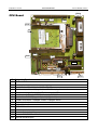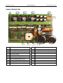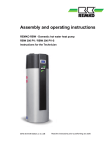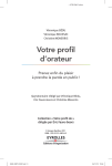
1
01/02 Rev. 2.13-03
SERVICE MANUAL
Service Boards, Seite 1
TTX x50/67x – Wildcats (plus) – S 45/65/95/105 – TDI/STDI/XXtreme
Service Boards
Handling boards ............................................ 2
CPU Board.................................................... 3
Stepper board ............................................... 4
Layout left half side.................................... 4
Layout right half side ................................. 5
Stepper board setting ................................ 6
Peripherals board .......................................... 9
Dispenser board.......................................... 10
Index ........................................................... 11
01/02 Rev. 2.13-03
SERVICE MANUAL
Service Boards, Seite 2
TTX x50/67x – Wildcats (plus) – S 45/65/95/105 – TDI/STDI/XXtreme
Handling boards
ESD protection
All of the (printed circuit) boards detailed below are equipped with, among
other things, large-scale integrated circuits. Voltage surges caused by static
charging from persons or objects can easily destroy the circuits.
Mind the following rules to protect your printer against damages caused by
electrostatic charge.
– When handling boards, make sure that you do not endanger the
electronic circuits by way of static charging or discharging.
– Before opening the printer, place it on a grounded surface.
– Earth your body using an ESD bracelet or other suitable means. If no
suitable ESD protection is available, touch an earthed object, e.g. a
heating radiator, before touching a board.
– Only place boards on earthed surfaces.
Handling
The conducting tracks of state-of-the-art multilayer boards are very thin.
Thus, if the board is bent or warped, the conducting tracks can easily crack.
Avoid bending or warping boards.
Avoid the use of excessive force when removing or inserting boards.
01/02 Rev. 2.13-03
SERVICE MANUAL
Service Boards, Seite 3
TTX x50/67x – Wildcats (plus) – S 45/65/95/105 – TDI/STDI/XXtreme
CN13
CPU Board
J4
J3
CN4
CN6
J5
1
J2
CN2
J8
IC13
IC10
CN12
CN11
ID
1
IC10
IC13
J2
J3
J4
J5
J8
CN2
CN4
CN6
CN9
CN11
CN12
CN13
Designation / Function
CPU Board 97191
Base for optional real-time clock
Base for interface-IC (serial interface RS485 – LTC 490)
Selection analog reference: J2 plugged =internal 5 V, J2 not plugged =external
Selection memory type: J3 plugged =8 MB, J3 not plugged =4 MB
Selection memory: J4 plugged =PROM, J4 not plugged =FLASH
Selection Vcc or A 18: 1-2 plugged =28 pin, 2-3 plugged =32 pin
Selection serial interface: 1-2 plugged =RS232, 2-3 plugged =RS485
Plug 2 stepper board
Plug 1 stepper board
PCMCIA slot 1 and 2
Connector standard-control panel
Connector Centronics interface
Connector RS232/RS485 serial interface
Connector film control panel
CN9
01/02 Rev. 2.13-03
SERVICE MANUAL
Service Boards, Seite 4
TTX x50/67x – Wildcats (plus) – S 45/65/95/105 – TDI/STDI/XXtreme
Stepper board
1
Layout left half side
P6
P5
P7
CN14
CN8
CN13
CN15
P1
P4
CN12
CN9
CN32
P8
CN30
CN16
CN35
P2
CN34
P9
CN10
CN17
CN31
CN18
CN23
CN26
CN2
ID
1
P1
P2
Function
Stepper board 97315
Pot. setting material end sensor (Mxx)
Pot. setting dispenser material transport
sensor(Xxx) / color sensor (CLxx)
P4 Pot. setting printhead sensor (Hxx)
P5 Pot. setting punch sensor (reflex, Rxx)
P7 Pot. setting punch sensor (light transm., Pxx)
P8 Pot. setting ribbon end sensor (Fxx)
P9 Pot. setting material speed Oxx
CN2 Ground connector
CN8 Connector data cable printhead
CN9
CN10
CN10
CN12
Connector material end sensor
Conn. dispenser mat. transport / color sensor
Connector TDI magazine top pos. sensor (Uxx)
Connector printhead sensor
ID
CN13
CN14
CN15
CN16
CN17
CN18
CN23
CN26
CN30
CN31
Function
Connector reflex punch sensor
Connector reflex sensor TDI magazine
Connector light transmission punch sensor
Connector ribbon end sensor
Conn. single start (TTX), material speed (TDI)
Hood switch
Conn. magazine bottom position sensor (TDI)
Power-Stacker (TDI)
Test point for setting material end sensor
Test point for setting dispenser mat. transp. /
color sensor
CN32 Test point for setting printhead sensor
CN34 Test point for setting ribbon end sensor
CN35 Connector fan
01/02 Rev. 2.13-03
SERVICE MANUAL
Service Boards, Seite 5
TTX x50/67x – Wildcats (plus) – S 45/65/95/105 – TDI/STDI/XXtreme
Layout right half side
1
CN19
CN20
CN21
CN29
JP1
R25
J1
ID
1
CN19
CN20
CN21
CN29
JP1
J1
J2
F1
F2
Function
I/O Board 97315
Connector printhead motor
Connector ribbon motor
Connector feed motor
Test point printhead voltage
Connector voltage cable printhead
Connector supply voltage (28 V AC)
Connector supply voltage (28 V AC)
Fuse 10 A slowblow
Fuse 1 A slowblow
F1
J2
ID
R25
F2
Function
Pot. setting printhead voltage (HVxx)
01/02 Rev. 2.13-03
SERVICE MANUAL
Service Boards, Seite 6
TTX x50/67x – Wildcats (plus) – S 45/65/95/105 – TDI/STDI/XXtreme
Stepper board setting
Setup all sensors as follows:
1. Select OTHR/SCHK (sensor check) in the parameter menu.
2. Press the CUT- or FEED-key until the parameter corresponding to the
sensor, which is to be set, shows up on the display (column „Display:
parameter“).
3. Arrange the setting condition (column „Setting condition“).
4. Change the setting by turning the corresponding potentiometer (column
„Pot.“) until the reading coincides with the entry in the column „Test point:
value“ or „Display: value“.
Photo. switches
• The settings of both types of punch sensors (light transmission and reflex)
are shown on the display.
• The settings of material end sensor, printhead sensor and ribbon end
sensor require the use of a voltmeter at the corresponding test point
(column „Test point“).
Mech. switches
• The switches "magazine limit switch" (TDI), "single start sensor" and "hood
switch" don´t require any settings. The displayed value – 0 or 15, corresponding to the switch position – indicates the correct function of the switch.
Refer to the values printed with gray background for setting. Make sure to
keep the photoelectric switches clear while setting. The values for
photoelectric switches with inserted material are only listed to countercheck the setting.
Printhead
The last row of the table below shows the conditions for the printhead
setting.
Set the head temperature (HV) to 99 before setting the voltage.
For details refer to topic section "Info-printouts and parameters", paragraph
"HV xx printhead temperature".
Don´t use the printer housing as a ground contact, but the ground contact
on the stepper board (CN2)!. Otherwise, you will set the voltage too high,
what will damage the printhead.
More detailed information about the parameter OTHR/SCHK can be found
in the subject section „Info Printouts and Parameters“.
Continue next page
01/02 Rev. 2.13-03
SERVICE MANUAL
Service Boards, Seite 7
TTX x50/67x – Wildcats (plus) – S 45/65/95/105 – TDI/STDI/XXtreme
Setting object
Connector
Setting condition
Pot. Voltage /
Test point
Material end sensor
CN9
Without material (sensor clear)
P1
Material inserted
Dispenser mat. transport
loop control (TTX)
CN10
Sensor clear
P2
Sensor covered
Color sensor
(TTX, Color-Option)
Separator sensor (TDI)
Printhead sensor
(printhead position)
Punch sensor / reflex
(TTX)
Magazine / reflex sensor
(TDI)
Punch sensor /
transmission
Ribbon end sensor
CN10
Without ribbon (sensor clear)
CN10
Ribbon inserted (sensor
covered)
Magazine at top position
(sensor clear)
Magazin not at top position
CN12
Sensor above recess of disc
(clear, econ. pos., printhead
raised)
CN13
Sensor covered
(print pos., printhead lowered)
Without material (sensor clear)
CN14
Material inserted
Reflex mark
White material
No sensor assembled
Without material (sensor clear)
CN15
Material inserted
Without material
CN16
Material inserted
Sensor above hole in oscillator
disc (sensor clear)
CN17
P2
P4
P5
P6
P7
P8
15
Xxx
Without material
Material inserted
check
0
15
CLxx
0
15
Uxx
0
15
Hxx
0
15
Rxxx
7
Sxx
>7
0...9
10...255
0
2...5
Pxxx
10...255
7
Fxx
>7
0
max. Wert
Turn P8
anti-clockwise to the
limit
>2,5 V /
CN34
check
Sensor covered
Single Start (TTX)
P2
<0,3 V /
CN30
>2,5 V /
CN30
<0,3 V /
CN31
>2,5 V /
CN31
<0,3 V /
CN31
>2,5 V /
CN31
<0,3 V /
CN31
>2,5 V /
CN31
Turn P4
anti-clockwise to the
limit
>2,5 V /
CN32
Display: Display:
ParaValue (xx)
meter
Mxx
0
15
Sxx
0
15
01/02 Rev. 2.13-03
SERVICE MANUAL
Service Boards, Seite 8
TTX x50/67x – Wildcats (plus) – S 45/65/95/105 – TDI/STDI/XXtreme
Setting object
Connector
Setting condition
Speed sensor (TDI)
CN17
Without material
Pot.
Hood closed
Hood open
Magazine at bottom position
Voltage / Display: Display:
Test point ParaValue (xx)
meter
<0,3 V / Oxx
0
CN33
15
>2,5 V /
CN33
check
Cxx
0
check
15
check
Dxx
0
Magazine not at bottom positon
check
P9
Material inserted
Hood switch
CN18
Magazine limit switch
(TDI)
CN23
Printhead voltage
CN29
Printhead
R25
25,5 V /
CN29
15
HVxx
99
Printhead voltage setting only in off line mode! Setting of the printhead
voltage while the printer is performing a print job is not possible!
01/02 Rev. 2.13-03
SERVICE MANUAL
Service Boards, Seite 9
TTX x50/67x – Wildcats (plus) – S 45/65/95/105 – TDI/STDI/XXtreme
Peripherals board
1
CN6
JP2
R41
CN4
CN5
CN3
P1
ID
1
JP2
P1
R41
CN3
CN4
CN5
CN6
Designation / Function
Peripherals board 99054
Can be applied with the options Applicator, Cutter, Rewinder, Infeed and Cutter-Stacker.
Connector signal/power, connection to dispenser board.
Pot. setting infrared-sensor
Pot. setting label present sensor (dispenser)
Connector infrared sensor.
Dependent on the applied option, the infrared sensor is being used in different ways:
Cutter-Stacker and Cutter:
No setting required.
Rewinder and Infeed:
Setting of P1 to reach a maximum of difference between both end positions (display).
Label present sensor:
Setting of R41 to a value of 2.5 V (indicated by a voltmeter applied at test point CN6; sensor clear and hood
closed).
Connector motor
Connector touch down / home sensor
Signal touch down:
Applicator plate contacts the product. The applicator changes direction and moves forward to home position.
Signal home sensor:
The Applicator is in home position.
Test point
01/02 Rev. 2.13-03
SERVICE MANUAL
Service Boards, Seite 10
TTX x50/67x – Wildcats (plus) – S 45/65/95/105 – TDI/STDI/XXtreme
Dispenser board
1
JP1
JP3
CN4
P2
JP2
ID
1
JP1
JP2
JP3
CN3
CN4
P2
CN3
Designation / Function
Dispenser board 99055
Connector main drive motor
Connector signal/power, connection to Peripherals board.
Connector material fixing motor
Connector main drive switch
Connector reflex sensor for backing paper
Pot. setting reflex sensor backing paper (parameter Wxx)
Setting to a maximum difference between the displayed values of backing paper inserted (low value) and
backing paper not inserted (high value).
01/02 Rev. 2.13-03
SERVICE MANUAL
Service Boards, Seite 11
TTX x50/67x – Wildcats (plus) – S 45/65/95/105 – TDI/STDI/XXtreme
Index
Control panel, connection ........................... 3
CPU-Board................................................. 3
Dispenser board ......................................... 9
Interface connector
Centronics ............................................... 3
Serial ....................................................... 3
Peripherals board ....................................... 8
Printed circuit boards, handling...................2
Real-time clock ...........................................3
Stepper board
layout, left half side ..................................4
layout, right half side ................................5
setting ......................................................6