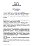
1
® SM Extended Warranty Program User’s Guide Shop online at omega.com ® e-mail: [email protected] For latest product manuals: omegamanual.info MADE IN CHINA OSXL160 Infrared Camera ® OMEGAnet ® Online Service omega.com Internet e-mail [email protected] Servicing North America: U.S.A.: ISO 9001 Certified Canada: Omega Engineering, Inc., One Omega Drive, P.O. Box 4047 Stamford, CT 06907-0047 USA Toll Free: 1-800-826-6342 TEL: (203) 359-1660 FAX: (203) 359-7700 e-mail: [email protected] 976 Bergar Laval (Quebec), H7L 5A1 Canada Toll-Free: 1-800-826-6342 FAX: (514) 856-6886 TEL: (514) 856-6928 e-mail: [email protected] For immediate technical or application assistance: U.S.A. and Canada: Sales Service: 1-800-826-6342/1-800-TC-OMEGA® Customer Service: 1-800-622-2378/1-800-622-BEST® Engineering Service: 1-800-872-9436/1-800-USA-WHEN® Mexico/ Latin America En Español: 001 (203) 359-7803 [email protected] FAX: 001 (203) 359-7807 e-mail: [email protected] Servicing Europe: Benelux: Managed by the United Kingdom Office Toll-Free: 0800 099 3344 TEL: +31 20 347 21 21 FAX: +31 20 643 46 43 e-mail: [email protected] Czech Republic: Frystatska 184 733 01 Karviná, Czech Republic Toll-Free: 0800-1-66342 FAX: +420-59-6311114 France: TEL: +420-59-6311899 e-mail: [email protected] Managed by the United Kingdom Office Toll-Free: 0800 466 342 TEL: +33 (0) 161 37 29 00 FAX: +33 (0) 130 57 54 27 e-mail: [email protected] Germany/Austria: Daimlerstrasse 26 D-75392 Deckenpfronn, Germany Toll-Free: 0800 6397678 FAX: +49 (0) 7056 9398-29 United Kingdom: ISO 9001 Certified TEL: +49 (0) 7056 9398-0 e-mail: [email protected] OMEGA Engineering Ltd. One Omega Drive, River Bend Technology Centre, Northbank Irlam, Manchester M44 5BD United Kingdom Toll-Free: 0800-488-488 TEL: +44 (0) 161 777-6611 FAX: +44 (0) 161 777-6622 e-mail: [email protected] It is the policy of OMEGA Engineering, Inc. to comply with all worldwide safety and EMC/EMI regulations that apply. OMEGA is constantly pursuing certification of its products to the European New Approach Directives. OMEGA will add the CE mark to every appropriate device upon certification. The information contained in this document is believed to be correct, but OMEGA accepts no liability for any errors it contains, and reserves the right to alter specifications without notice. WARNING: These products are not designed for use in, and should not be used for, human applications. OSXL160 Infrared Camera User Manual Please read carefully before first use WARNING DO NOT USE WHEN RAINING! DO NOT OPEN OR EXCHANGE PARTS! REPAIR ONLY CAN BE CONDUCTED BY STUFF! NOTICE z In order not to cause malfunction or even damage the device please do not direct the lens towards strong high-temperature radiation source (such as the sun) whether the power is on or off! z Avoid violent shock and impact during operation or transport. z Storage temperature is between -40ć and 60ć. The device must be kept in original packing case during transport. z Typical storage place is cool, dry, ventilated, and without strong electromagnetic field. z Keep the lens surface off grease or any chemical substance which would damage the lens. Close the lid after operation. z Please regularly backup data on PC to prevent potential data loss and format the internal FLASH memory duly to make it operate properly. Table of Contents 1. 2. 3. 4. 5. Product Summary .................................................. 1 1.1 Standard Item List ................................................ 2 Battery and Charger............................................... 3 2.1 Charging Battery .................................................. 4 2.2 Direct Charging .................................................... 4 2.3 Attention for Using Battery Charger...................... 4 Panel Function Summary ...................................... 5 3.1 Main Control Panel............................................... 5 3.2 Rear Interface Panel ............................................ 6 3.3 Side View ............................................................. 7 Quick Start Reference............................................ 8 4.1 Infrared Image ...................................................... 8 4.2 Measure Target Temperature............................... 8 4.3 Infrared Image and Voice Annotation ................... 9 4.4 Infrared Image Playback ...................................... 9 4.5 Replace Lens ....................................................... 9 4.6 Connect to PC .................................................... 10 Operation Menu.................................................... 10 5.1 Display Summary ............................................... 10 5.2 Main Menu ......................................................... 12 5.2.1 File.............................................................. 13 Manage..................................................... 14 Save ......................................................... 16 Format ...................................................... 16 5.2.2 Measure ..................................................... 16 Spot Measure ........................................... 17 Line Measure ............................................ 19 Horizontal Line Measure ....................... 19 Vertical Line Measure ........................... 20 Area (Rect) Measure ................................ 20 Parameters ............................................... 22 Emissivity .............................................. 23 Distance ................................................ 23 Humidity ................................................ 23 Adjust Ratio........................................... 23 i 6. 7. 8. 9. ii Adjust Temp.......................................... 23 Save Setting ............................................. 24 5.2.3 Image ......................................................... 24 Image Setup ............................................. 25 Alarm Switch ......................................... 25 Alarm Temp .......................................... 25 Alarm Color ........................................... 26 Isotherm Color ...................................... 26 Isotherm Temp...................................... 26 Isotherm Width...................................... 26 Screen Display...................................... 26 Analysis Setup .......................................... 27 Temp Range ......................................... 27 IR Lens.................................................... 2 Temp Unit ............................................. 27 Ambient Temp....................................... 27 Reference ............................................. 27 Ref Temp .............................................. 28 Image Reverse ......................................... 28 Clear Screen............................................. 28 L&S (Auto/Manual Mode).......................... 28 5.2.4 Setup .......................................................... 28 System Setup ........................................... 29 Language .............................................. 30 Auto Rectify........................................... 30 Auto Save ............................................. 30 Video..................................................... 30 Transparence........................................ 30 Display Device ...................................... 30 Screen Save ......................................... 30 Power Save........................................... 30 Time & Date.............................................. 31 Factory Default ......................................... 31 Information................................................ 31 Building Thermal Imaging Summary.................. 32 Technical Specification ....................................... 35 Technical Support................................................ 38 Appendix: Emissivity of Raw Material................ 39 1. Product Summary This new generation OSXL160 Infrared Camera (equipped with Uncooled Focal Plan Array Micro-bolometer) produces crisp thermal image and accurate temperature reading to help increase system maintenance quality and efficiency in many industries. THE OSXL160 Infrared Camera is packed with advanced features, such as colored thermal image, voice annotation, sound and color alarm, FLASH memory storage, USB connection to PC, and analysis software. Crisp thermal image, accurate temperature reading, clear user interface, reliable product quality, and affordable cost makes OSXL160 Infrared Camera the new standard in Infrared imaging industry! Typical Application: z z z z z z Power Plant: Monitor and diagnose the condition of electrical wire and equipment, detect power leak, and prevent system malfunction Petrochemical Industry: oil pipeline check, material interface detect, heat leakage, insulation structure and power equipment detect. Fire Protection: forest fire protection and latent fire source search, self-ignition prevention and detection of special material, electric fire precaution detect. Medical Application: Accurately measure human body temperature in a distance, critical under a contaminated condition Building Industry: humidity, air leakage and insulation defects detect. Other Applications: Civil engineering, university research, and railway etc. 1 1.1 Standard Item List OSXL160 Infrared Camera comes with the following standard items and accessories: Item Quantity OSXL160 Infrared Camera 1 Li-Ion Battery 2 Battery Charger 1 USB Cable 1 Video Cable 1 User Manual 1 IR See Software CD 1 Suitcase 1 2 2. Battery and Charger It is recommended to charge battery immediately when device indicates low power. By press and move in the indicated direction, user can easily insert and remove battery. Battery Insertion Battery Removal Device comes with two sets of Li-Ion battery and one battery charger. It is strongly recommended to operate only with the included battery and charger. Use any other brand charger or Li-Ion battery may cause fire or critical damage. 3 2.1 Charging Battery 1) Following the direction indicated on battery charger, insert the Li-Ion battery, press firmly and push all the way in. 2) During charging, the red LED will be on, and when charging is completed, the green LED will be on instead. : Normally it takes 3 hours to completely charge one battery. 2.2 Direct Charging 1) The battery can also be charged by using an adapter. Normally it takes 5 hours to charge one battery in this mode. 2.3 Attention for Using Battery Charger 1) 2) 3) 4) 5) 4 Battery Charging can only be conducted inside of a house. Do not short-circuit the battery. Do not put the battery in high temperature environment (60ć). Never disassemble the battery or put it into fire, which may cause explosion. Do not try to modify the battery or the charger. Please remove the charger from AD socket as soon as charging is completed. 3. Panel Function Summary In this manual, “long press” means Long press button down for about 2 seconds, and “press” or “short press” means press and release. 3.1 Main Control Panel 1. Power ON/OFF Button Long press this button to turn on or off the device. 2. Power LED Light When device is powered on, the Power LED Light will be on. 3, 4, 5, 6. Direction Buttons Up (Ÿ), Down (ź), LeftƷ( ), and Rightͩ( ), 4 direction buttons have different usage in different mode. In main menu, direction buttons are used for moving selected items or changing slide-bar value. In real time Infrared view mode, directions buttons provide one-click access: Ʒ to freeze Infrared image and press again to unfreeze Press 5 Ʒ to save current Infrared image Long press Press Ÿ or ź to switch between normal view and 2X zoom G Q D After press Hotkey button (refer page 8, 3.3) and in area measure mode: Ʒ , and ͩ to move z Select the measure spot; press Ÿ, ź, the spot in the same direction. Ʒ , z Select the measure line and sampling line; press Ÿ, ź, ͩ to move the line in the same direction. and Ʒ , ͩ z Select area box: in move menu, press Ÿ, ź, Ʒ ͩ moves area box, and in size menu, press Ÿ, ź, , resizes area box. z Select Color Palette or temperature measurement limit: Ʒ ͩ , to change, and Ÿ, ź has no effects. Press 7. OK (Menu/Confirm) Button This button has different functions under different conditions: z In real time Infrared view mode, press this button opens the main menu. z In main menu, press this button to confirm operation. z In real time Infrared view mode, long press this button to manually rectify measurement result. z In image viewing mode, long press this button to exit. : After auto rectifying, if device has abnormal noise, long press OK button to perform manual rectifying usually solves such issues. 8. MIC Internal MIC records audio annotation. 9. Laser Sight Long press Hotkey button to turn on/off laser sight. 6 3.2 Rear Interface Panel 10. Video Output CVBS standard video output. 11. Audio Output Audio output playbacks recorded voice annotation. 12. USB 2.0 Interface USB2.0 interface transfers data between device and PC. 13. External DC In External DC requirement is 12V. 3.3 Side View 14. Hotkey Button 7 Press Hotkey button to switch between Color Palette, area measurement rectangle, temperature limits, and long press Hotkey button to turn on/off laser sight. 15. Sound Alarm Buzzer Signal sound alarm when reaches temperature limit. 4. Quick Start Reference 4.1 Infrared Image 1. 2. 3. 4. Insert Li-Ion battery correctly. Long press Power button until LED light is on and wait until system finishes initialization. Remove IR Lens lid if closed, point to target, and adjust focus to get crisp thermal image. Long press OK button to rectify thermal image. 4.2 Measure Target Temperature 1. Point device to measurement target, and adjust to correct focus. On the upper-right LCD corner, *=×× displays the spot measurement result. For better accuracy, long press OK button to perform manual rectify. 2. Select Area (Rect) Measurement to measure max, min, and average temperature within a rectangle box. Ʒ button to freeze thermal image 3. It is recommended to press Ʒ first, and then apply different and detailed analysis. Press button one more time to unfreeze. 4. Press Ÿ button or ź button to switch between normal and 2X zoom. Upper-left LCD corner displays ×2 when in 2X zoom. 5. When measure result is outside temperature range, screen display changes to indicate either below or above temperature range. 8 4.3 Infrared Image and Voice Annotation Each thermal image can save up to 40 seconds voice annotation data. Image and voice annotation can later be reviewed on PC by Ʒ bundled IRSee software. To save Infrared image, first press Ʒ button again to button to freeze image, and then long press open the voice recording menu. If only needs store Infrared image, select Cancel, otherwise select Record. Press OK button to confirm. In main menu, File Æ Save provides the same function. : Select Cancel during voice recording to exit. 4.4 Infrared Image Playback 1. 2. 3. 4. 5. Press OK button to open main menu. Select File Æ Manage, and select folder to view stored thermal image. Ʒ button or ͩ button to When viewing thermal image, press switch image in the same folder. The icon indicates voice annotation attached to current thermal image. Press Ÿ button to playback. Long press OK button to exit. 4.5 Replace Lens 1. Screw off the lens on device, replace it with another lens and screw on tightly. 9 Screwing off Screwing on Ʒ ͩ to adjust “IR Lens” in “Analysis Setup” menu. 2. Press or 3. Operate Image Save and Image Playback according to the steps mentioned in 4.3 and 4.4 hereinabove. 4.6 Connect to PC Connect device to PC using included USB cable. Refer OSXL160 software manual for additional PC operation instruction. It is recommended to format device periodically. 5. Operation Menu 5.1 Display Summary All items can be selected by short pressing the Hotkey button (Note: Long press Hotkey button will turn on/off laser sight). The 10 selected item is flashing in yellow color. If no operation in 2 seconds after selection, Hotkey mode will exit automatically. Real Time Thermal Image Interface 1 2, 4 3 5 6 7 8 9 10 11 12 Symbol for 2X zoom: symbol 2X denotes enlarge twice in size; press Ÿǃź button to realize the function. Area measure box: 3 areas can be selected in area measure mode. Horizontal measure line: Horizontal sampling line. Temperature unit: there are three options: ćǃ̧ǃK. Battery condition: indicates current battery power condition. 1, 2, 3 and 4 indicates Point measure˖ temperature value of point 1, 2, 3 and 4 respectively. Line measure: the temperature value in the crossing of measure line and cursor line. Area measure: measure points within the area (maximum, minimum or average temperature is optional) Temperature distribution curve: sample temperature distribution curve of the measure line. Point measure cursor: 4 measure points can be selected. Cursor line: it appears in line measure mode. 11 13, 15 Lower limit temperature, upper limit temperature: the lower and upper limit temperature of the color code at the same time. 14 Color code: color palette. Any kind of color code is available in the palette. 5.2 Main Menu Menu and sub-menu items: Press OK button (when not in Hotkey mode) to enter main menu. Note if press OK button too long, instead of enter main menu, triggers manual rectify. 12 Main Menu Using Ÿ and ź button to select menu item, and selected item is ͩ button to enter highlighted with white background. Press OK or Ʒ button to return to previous menu or exit. sub-menu. Press 5.2.1 File Using File menu to save, playback, delete thermal image and voice annotation. File Sub-menu 13 Manage Select Manage to preview thermal image, add or edit voice annotation, or delete thermal image. File Manage Folder is automatically created if not exist when saving thermal image. Folder name is MYYMMDD, and YYMMDD is year, month, and date. For example, Jan 2nd, 2009 folder is M090102. All thermal images taken in this day is saved in this folder. Thermal image file name is Phhmmss, and hhmmss is hour, minute, second (according to system time). For example, P080502 in folder M090102 means the thermal image taken at 08:05:02 time in Jan 2nd, 2009. In File Manage window, press Ÿ and ź button to select items. Ʒ and ͩ Selected item is highlighted with red background. Press button to switch folder or file when highlighted. After select thermal image, press Open to view thermal image or Delete to delete. Press Exit to exit File Manage window. 14 Thermal Image preview Ʒ or ͩ button to switch saved thermal image in the same Press icon indicates voice annotation data with current folder. The thermal image. Long press Ÿ button to enter Voice Annotation menu. If voice annotation already exists, press Record will record new voice annotation and erase previously saved one. Press Cancel first to stop recording then press Save to save. Voice Annotation Long press ź button to delete thermal image. 15 Delete Saved Thermal Image To exit thermal image playback, long press OK button. Save Save current thermal image. Freeze image first before saving. Format Format the internal FLASH memory. Press OK to confirm or cancel to exit. Format will erase all saved thermal images. It is recommended to transfer data to PC before format. 5.2.2 Measure There are 5 items: Spot, Line, Area (Rect), Parameters, and Save Setting in Measure menu. 16 Measure Sub-menu Spot Measure Ʒ or ͩ button to select or deselect. Selected spot is check Press marked. Up to 4 spots can be selected at the same time. Spot Target Selection 17 Spot Measure Measure result on upper-right LCD corner is temperature reading . Up to 4 spots can be selected. at location marked with Spot Measure Attribute Press Hotkey button until spot marker is flashing in yellow, and Ʒ ͩ , buttons to move spot location to different then use Ÿ, ź, directions. Press OK button to enter Attribute Menu. After 2 seconds with no operation, system will exit to real time Infrared view screen. Spot Measure Attribute 18 Emissivity: Refer to Appendix Emissivity of raw materials. Set Reference: Set current spot as reference point. If selected, all measure result will be relative value to this spot temperature. Line Measure There are 2 line measure options: vertical and horizontal. Horizontal Line Measure Horizontal Line Measure Horizontal line is temperature sampling line, and upper-right LCD corner displays temperature measurement reading on vertical cursor line intersection. After using Hotkey button select line measure, press Ÿ and ź button to adjust sampling line position, Ʒ and ͩ button to adjust cursor line position. Press and press OK button to enter Attribute Menu. After 2 seconds with no operation, system will exit to real time Infrared view screen. 19 Vertical Line Measure Vertical Line Measure Vertical line is temperature sampling line, and upper-right LCD corner displays temperature measurement reading on horizontal cursor line intersection. After using Hotkey button select line Ʒ and ͩ button to adjust sampling line position, measure, press and press Ÿ and ź button to adjust cursor line position. Press OK button to enter Attribute Menu. After 2 seconds with no operation, system will exit to real time Infrared view screen. Area (Rect) Measure Ʒ or ͩ button to select or deselect. Selected Area is check Press marked. Up to 3 areas can be selected. 20 Area (Rect) Target Selection Area (Rect) Measure Measure result on upper-right LCD corner is the temperature measurement result within the corresponding rectangle. There are 3 measure types: max, min, and average temperature. 21 Area (Rect) Measure Attribute: Press Hotkey button until area rectangle is flashing in yellow. Press OK button to enter Attribute Menu in which four parameters can be adjusted namely: emissivity, set reference, measure type, move /size. Emissivity: Refer to Appendix: Emissivity of raw materials. Set Reference: Set current area as reference. If selected, all measure result will be relative value to this temperature. Measure Type: Select from max, min, and average. Adjust: Adjust rectangle position and size. Parameters Change different settings to adjust temperature measurement accuracy. Press Ÿ and ź button to select different parameters, Ʒ and ͩ button to change value. and press Parameter Sub-menu 22 Emissivity Emissivity varies based on target subject material, surface temperature, surface roughness, measurement angle, and etc. Ʒ or ͩ once to change Emissivity by 0.01. Long press Ʒ Press ͩ will change Emissivity in 0.1 intervals. or Distance This value can be omitted if target subject is close to device (less than 10m). Otherwise, set Distance value accordingly to get more Ʒ ͩ or once to change accurate temperature reading. Press Ʒ or ͩ will change Distance in 1m Distance 0.1m. Long press interval. Humidity This value can be omitted if target is close to device (less than 10m). Otherwise, set Humidity value according to environmental Ʒ ͩ or once to change Humidity 1%. Long condition. Press Ʒ or ͩ will change Humidity in 10% interval. press Adjust Ratio Due to long time usage of device, the sensitivity of IR detector may decrease. In such case, it is necessary to adjust ratio value to get more accurate temperature reading. During calibration, if temperature reading is higher than actual target temperature, Ʒ or ͩ once to change ratio value lower, and vise versa. Press Ʒ or ͩ will change ratio change ratio value 0.01. Long press value in 0.1 intervals. Adjust Temp Under certain condition, it is necessary to adjust temperature reading by a pre-define value. Normally this option should be left Ʒ or ͩ once to change 0.1ć. Long press Ʒ unchanged. Press ͩ will change this value in 1ć interval. or 23 Save Setting All parameter changes must be saved before power off device. Otherwise, changes will not be saved for next power on. 5.2.3 Image There are 5 items: Image Setup, Analysis Setup, Image Reverse, Clear Screen, and Auto/Manual (L&S) in Image menu. Image Sub-menu 24 Image Setup Image Setup Sub-menu Alarm Switch Ʒ or ͩ turns on or off the alarm function. If the Alarm Press Switch is on, when target subject within area box has surface temperature exceeding Alarm Temp, device will alarm with buzzer sound and mark the high temperature location as Alarm Color if Alarm Color is set. Alarm Temp When Alarm Switch is off, this option is disabled. When Alarm Switch is on, Alarm Temp is the desired alarm temperature. Press Ʒ or ͩ once to change Alarm Temp 0.1ć. Long press Ʒ or ͩ will change Alarm Temp in 1ć interval. Default setting is 37.0ć. 25 Alarm Color Alarm Color can select from Auto, Black, White, Red, Orange, Yellow, Green, Blue, Gray, and Purple. Default setting is Auto, which is no color alarm. Isotherm Color When this option is Auto, there is no Isothermal display. Otherwise, target subject Infrared image will change to selected color when temperature is within the range of (Isothermal Temp ± Isothermal Width/2). Default setting is Auto. Isotherm Temp Ʒ ͩ or once to change Isothermal Temp 0.1ć. Long Press pressƷ orͩ will change Isothermal Temp in 1ć interval. Default setting is 37.0ć. Isotherm Width Adjust Isothermal Width to change the range of Isothermal Color Ʒ or ͩ once to change Isothermal Width 0.1ć. display. Press Ʒ or ͩ will change Isothermal Width in 1ć interval. Long press Default setting is 1.0ć. Screen Display When this option is Off, screen display will clear battery condition, Ʒ or temperature unit, temperature limit, and color palette. Press ͩ to turn on/ off this option. 26 Analysis Setup Analysis Setup Sub-menu Temp Range Select Temperature range base on measure target temperature from 2 options: standard grade (-20/120ć) and medium grade (0/350ć). Extra grade (300/1200ć) which is customized high temperature measurement. Temp Unit Ʒ or ͩ Press to select Temperature Unit from ć, ̧, and K. ̧=9/5*ć+32ˈK=273.15+ć Ambient Temp For more accurate measure result, set Ambient Temp to correct orͩ once to change environmental temperature. PressƷ Ʒ ͩ Ambient Temp 0.1ć. Long press or will change Ambient Temp in 1ć interval. Reference 27 Set reference spot or area to display measure results as relative value. Ref Temp Ʒ or ͩ Press Ʒ or once to change Ref Temp 0.1ć. Long press ͩ will change Ref Temp in 1ć interval. This option is only active when set Ref Temp as reference. Image Reverse Press OK button to reverse palette for thermal image display. Press OK again to switch back. Clear Screen Press OK button to clear all screen items except Logo mark. L&S (Auto/Manual Mode) Press OK button to switch between auto and manual rectifying. In manual rectifying mode, upper-left corner of LCD display shows L&S. 5.2.4 Setup There are 4 items in Setup menu: System Setup, Time & Date, Factory Default, and Information. 28 Setup Sub-menu System Setup System Setup includes: Language, Auto Rectify, Auto Save, Video, Transparence, Display Device, Screen Save, and Power Ʒ Save. Press Ÿ and ź button to switch selection, and press ͩ button to adjust value. Active item is highlighted with red and background. System Setup Sub-menu 29 Language There are 11 different language options: Simplified Chinese, Traditional Chinese, English, Korean, Japanese, German, French, Russian, Italian, Portuguese and Spanish. Auto Rectify Set the number of seconds to perform next auto-rectify. Set value between 1 and 3000 seconds. Value 0 means disabling auto-rectify feature. Auto Save Set the number of seconds to perform next auto-save. Set value between 5 to 3600 seconds. Value 0 means disabling auto-save Ʒ or ͩ once to change the value by 1 second. feature. Press Ʒ or ͩ will change the value in 10 intervals. Long press Video Select between PAL and NTSC. Transparence Set to enable or disable menu transparence feature. Display Device Select between LCD display and external monitor device. Only one video output device can be selected at one time, the other one will be disabled. : If accidentally selected external monitor device and LCD display is disabled, power off and power on device to get LCD display back. Screen Save Set the number of minutes without operation to trigger disabling LCD display to save power. Select between 5min, 10min, 30min, and None. Power Save 30 Set the number of minutes without operation to trigger power off completely. Select between 10min, 20min, 30min, and None. Time & Date Set system date and time. Press Ʒ or ź button to select an item, ϧ or ϰ button to change its value and press OK button to press confirm. If Li-Ion battery is removed for a long time, it is necessary to reset system time and date. Factory Default Restore factory default and rectify some improper settings. Information Select to display system information, such as: serial number, software version, and production date etc. 31 6. Building Thermal Imaging Summary As the quality of life improves and the low-carbon life style becomes known, higher demands are being set on buildings. The features of our TI series IR camera make it possible to detect slight temperature difference and to analyze indoor humidity and leakage. Hereinafter are images in some cases. The effect drawing of building detection The effect drawing of indoor humidity 32 The effect drawing of indoor water leakage The effect drawing of indoor corner air leakage 33 The effect drawing of outdoor corner air leakage 34 7. Technical Specification Type IR Detector Resolution 160×120 Pixel Spacing 25 m Standard Lens 21°×16°/0.15m Spatial Resolution Infrared Image Quality Frame-frequency 50/60Hz Focusing Manual 2X Spectral Range 8~14 m LCD 3.5" Color LCD Temperature Range Accuracy Measure rectification Measure 1mrad/f=25mm Thermal Sensitivity Digital Zoom Display New UFPA micro-bolometer Measure Mode Color Palette Image Setup -20 +120 / 0 +350 +350 +1200 customized ±2 or ±2%(reading range), select the bigger value Auto/Manual 4 spots, 3 areas available under real time mode(max, min and average temp) line measure, isothermal display, temp difference measure and temp alarm (sound/color) 12 Colors selectable (including iron red, rainbow, black-white, and white-black etc.) Auto/Manual adjust contrast, brightness System Setup Emissivity Rectification Ambient Temp Rectification Atmospheric Trans Correction 36 Date, Time, Temperature Unit ć/̧/K 10 Languages available, namely: Chinese (simplified & traditional), English, Italian, Japanese, Russian, French, German, Korean, Spanish and Portuguese. Adjustable from 0.01 to 1.0 Auto, according to background temperature input Auto, according to distance, relative humidity, ambient temperature input Continued table: Technical Specification Storage Laser Power Supply Operating Condition Storage Media (Built-in Memory) Up to over 1500 images Storage Mode Auto/Manual single frame image storage File Type JPEG, with 14 bits measure data Voice Annotation 40 Seconds voice recording per image (built-in microphone) Director Class 2, 1mW/635nm Red Battery Type Rechargeable Li-Ion Battery Battery Operating Time 3 Hours (Under normal temperature) Charging type Intelligent charger Power Save Included External Power 12V±5% DC Operation Temperature Storage Temperature -20ć~ +50ć -40ć~ +60ć Humidity 90Č (non condensing) Protection Grade IP54 Weight 660g Size (L×W×H) 330mm×95mm×86mm Physical 37 8. Technical Support For common mistakes and issues during operation, please refer the following form. If issue cannot be resolved, please contact our technical support department. For simple problems arising during operation, please refer to the following table. If the problem cannot be settled, please cut off the power and contact our technical department. Problem Cause and Solution z Camera cannot be powered on z z Device power off automatically Battery power is soon used up No thermal image Thermal image is black and white 38 No battery or batteries are not installed correctly ĺ Install battery correctly. Battery power is used up. ĺ Change battery or recharge. Save power mode ĺpower on after 5 seconds. z Battery power is used up. ĺ Change battery. z z Ambient temperature is too high or low. Battery is not fully charged. ĺ recharge battery fully. Battery may already reach end of life. (300 usage cycles) ĺ use new battery to charge. z z Lens lid is closed. ĺ Remove lens lid. z Black & white palette may be selected. ĺrestore factory default. 9. Appendix: Emissivity of Raw Material ˄For reference purpose only˅ Material Aluminum Brass Copper Iron Cast Iron Wrought Iron Surface Temp (ć) Emissivity (İ) inoxidized 100 0.20 Oxidized Brown polished 100 20 0.55 0.40 Unpolished Oxidized Oxidized badly Oxidized 38 100 20 100 0.22 0.61 0.78 0.74 Rusted Oxidized 25 200 0.65 0.64 inoxidized Rough 100 25 0.21 0.94 Polished Oxidized 38 200 0.28 0.37 Nickel Stainless Steel Steel Oxidized 60 0.85 800ć Oxidized 200 0.79 Brick Concrete --- 20 20 0.93 0.92 Glass Smooth flat White 20 100 0.94 0.92 Natural Black 100 0.97 Smoky black 25 0.95 Candle smoke Black-lead rough 16 Color average White -Polished -Human Fine Rough 20 20 100 20 20 30 30 32 21 21 0.95 0.98 0.94 0.93 0.90 0.90 0.96 0.98 0.90 0.93 Lacquer Carbon Paint Paper Soil Wood Water Skin China 39 WARRANTY/DISCLAIMER OMEGA ENGINEERING, INC. warrants this unit to be free of defects in materials and workmanship for a period of 13 months from date of purchase. OMEGA’s WARRANTY adds an additional one (1) month grace period to the normal one (1) year product warranty to cover handling and shipping time. This ensures that OMEGA’s customers receive maximum coverage on each product. If the unit malfunctions, it must be returned to the factory for evaluation. OMEGA’s Customer Service Department will issue an Authorized Return (AR) number immediately upon phone or written request. Upon examination by OMEGA, if the unit is found to be defective, it will be repaired or replaced at no charge. OMEGA’s WARRANTY does not apply to defects resulting from any action of the purchaser, including but not limited to mishandling, improper interfacing, operation outside of design limits, improper repair, or unauthorized modification. This WARRANTY is VOID if the unit shows evidence of having been tampered with or shows evidence of having been damaged as a result of excessive corrosion; or current, heat, moisture or vibration; improper specification; misapplication; misuse or other operating conditions outside of OMEGA’s control. Components in which wear is not warranted, include but are not limited to contact points, fuses, and triacs. OMEGA is pleased to offer suggestions on the use of its various products. However, OMEGA neither assumes responsibility for any omissions or errors nor assumes liability for any damages that result from the use of its products in accordance with information provided by OMEGA, either verbal or written. OMEGA warrants only that the parts manufactured by it will be as specified and free of defects. OMEGA MAKES NO OTHER WARRANTIES OR REPRESENTATIONS OF ANY KIND WHATSOEVER, EXPRESS OR IMPLIED, EXCEPT THAT OF TITLE, AND ALL IMPLIED WARRANTIES INCLUDING ANY WARRANTY OF MERCHANTABILITY AND FITNESS FOR A PARTICULAR PURPOSE ARE HEREBY DISCLAIMED. LIMITATION OF LIABILITY: The remedies of purchaser set forth herein are exclusive, and the total liability of OMEGA with respect to this order, whether based on contract, warranty, negligence, indemnification, strict liability or otherwise, shall not exceed the purchase price of the component upon which liability is based. In no event shall OMEGA be liable for consequential, incidental or special damages. CONDITIONS: Equipment sold by OMEGA is not intended to be used, nor shall it be used: (1) as a “Basic Component” under 10 CFR 21 (NRC), used in or with any nuclear installation or activity; or (2) in medical applications or used on humans. Should any Product(s) be used in or with any nuclear installation or activity, medical application, used on humans, or misused in any way, OMEGA assumes no responsibility as set forth in our basic WARRANTY/ DISCLAIMER language, and, additionally, purchaser will indemnify OMEGA and hold OMEGA harmless from any liability or damage whatsoever arising out of the use of the Product(s) in such a manner. RETURN REQUESTS/INQUIRIES Direct all warranty and repair requests/inquiries to the OMEGA Customer Service Department. BEFORE RETURNING ANY PRODUCT(S) TO OMEGA, PURCHASER MUST OBTAIN AN AUTHORIZED RETURN (AR) NUMBER FROM OMEGA’S CUSTOMER SERVICE DEPARTMENT (IN ORDER TO AVOID PROCESSING DELAYS). The assigned AR number should then be marked on the outside of the return package and on any correspondence. The purchaser is responsible for shipping charges, freight, insurance and proper packaging to prevent breakage in transit. FOR WARRANTY RETURNS, please have the following information available BEFORE contacting OMEGA: 1. Purchase Order number under which the product was PURCHASED, 2. Model and serial number of the product under warranty, and 3. Repair instructions and/or specific problems relative to the product. FOR NON-WARRANTY REPAIRS, consult OMEGA for current repair charges. Have the following information available BEFORE contacting OMEGA: 1. Purchase Order number to cover the COST of the repair, 2. Model and serial number of the product, and 3. Repair instructions and/or specific problems relative to the product. OMEGA’s policy is to make running changes, not model changes, whenever an improvement is possible. This affords our customers the latest in technology and engineering. OMEGA is a registered trademark of OMEGA ENGINEERING, INC. © Copyright 2011 OMEGA ENGINEERING, INC. All rights reserved. This document may not be copied, photocopied, reproduced, translated, or reduced to any electronic medium or machine-readable form, in whole or in part, without the prior written consent of OMEGA ENGINEERING, INC. Where Do I Find Everything I Need for Process Measurement and Control? OMEGA…Of Course! Shop online at omega.com sm TEMPERATURE 䡺 ⻬ 䡺 ⻬ 䡺 ⻬ 䡺 ⻬ 䡺 ⻬ Thermocouple, RTD & Thermistor Probes, Connectors, Panels & Assemblies Wire: Thermocouple, RTD & Thermistor Calibrators & Ice Point References Recorders, Controllers & Process Monitors Infrared Pyrometers PRESSURE, STRAIN AND FORCE 䡺 ⻬ 䡺 ⻬ 䡺 ⻬ 䡺 ⻬ Transducers & Strain Gages Load Cells & Pressure Gages Displacement Transducers Instrumentation & Accessories FLOW/LEVEL 䡺 ⻬ 䡺 ⻬ 䡺 ⻬ 䡺 ⻬ Rotameters, Gas Mass Flowmeters & Flow Computers Air Velocity Indicators Turbine/Paddlewheel Systems Totalizers & Batch Controllers pH/CONDUCTIVITY 䡺 ⻬ 䡺 ⻬ 䡺 ⻬ 䡺 ⻬ pH Electrodes, Testers & Accessories Benchtop/Laboratory Meters Controllers, Calibrators, Simulators & Pumps Industrial pH & Conductivity Equipment DATA ACQUISITION 䡺 ⻬ 䡺 ⻬ 䡺 ⻬ 䡺 ⻬ 䡺 ⻬ Data Acquisition & Engineering Software Communications-Based Acquisition Systems Plug-in Cards for Apple, IBM & Compatibles Data Logging Systems Recorders, Printers & Plotters HEATERS 䡺 ⻬ 䡺 ⻬ 䡺 ⻬ 䡺 ⻬ 䡺 ⻬ Heating Cable Cartridge & Strip Heaters Immersion & Band Heaters Flexible Heaters Laboratory Heaters ENVIRONMENTAL MONITORING AND CONTROL 䡺 ⻬ 䡺 ⻬ 䡺 ⻬ 䡺 ⻬ 䡺 ⻬ 䡺 ⻬ Metering & Control Instrumentation Refractometers Pumps & Tubing Air, Soil & Water Monitors Industrial Water & Wastewater Treatment pH, Conductivity & Dissolved Oxygen Instruments M5045/1111