1
VOLVO V70 & XC70
Owners Manual
Web Edition
DEAR VOLVO OWNER
THANK YOU FOR CHOOSING VOLVO
We hope you will enjoy many years of driving pleasure in your Volvo.
The car has been designed for the safety and comfort of you and your
passengers. Volvo is one of the safest cars in the world. Your Volvo
has also been designed to satisfy all current safety and environmental
requirements.
In order to increase your enjoyment of the car, we recommend that
you familiarise yourself with the equipment, instructions and maintenance information contained in this owner's manual.
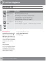
Table of contents
00 01 02
4
00 Introduction
01 Safety
Important information................................. 8
Volvo and the environment....................... 13
Seatbelts ..................................................
Airbags......................................................
Activating/deactivating the airbag*...........
Side airbags (SIPS bags) .........................
Inflatable Curtain (IC) ...............................
WHIPS ......................................................
When the systems deploy ........................
Safety mode..............................................
Child safety...............................................
* Option/accessory, for more information, see Introduction.
02 Locks and alarm
18
21
24
26
28
29
31
32
33
Remote control key/key blade..................
Privacy locking*.........................................
Battery replacement, remote control key/
PCC*.........................................................
Keyless drive*............................................
Locking/unlocking.....................................
Child safety locks......................................
Alarm*.......................................................
48
53
55
57
60
65
66
Table of contents
03 04 05
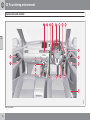
03 Your driving environment
04 Comfort and driving pleasure
05 Infotainment system
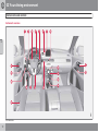
Instruments and controls.......................... 72
Volvo Sensus ........................................... 81
Key positions............................................ 82
Seats......................................................... 84
Steering wheel.......................................... 89
Lighting..................................................... 90
Wipers and washing................................ 100
Windows, rearview and door mirrors...... 103
Compass*............................................... 108
Power sunroof*....................................... 109
Alcoguard*.............................................. 111
Starting the engine.................................. 115
Starting the engine – Flexifuel................. 117
Starting the engine – external battery..... 119
Gearboxes............................................... 120
Eco DRIVe*.............................................. 126
All-wheel drive – AWD*........................... 131
Foot brake............................................... 132
HDC Hill Descent Control....................... 134
Parking brake.......................................... 136
Menus and messages............................. 146
Menu source MY CAR............................ 148
Climate control........................................ 156
Fuel-driven engine block heater and passenger compartment heater*.................. 166
Additional heater*.................................... 169
Trip computer......................................... 170
DSTC – Stability and traction control system.......................................................... 172
Adapting driving characteristics............. 174
Cruise control*........................................ 175
Speed limiter .......................................... 177
Adaptive cruise control*.......................... 179
Distance Warning*.................................. 189
City Safety™........................................... 192
Collision Warning with Auto Brake &
Pedestrian detection*.............................. 196
Driver Alert System – DAC*..................... 203
Driver Alert System - LDW*..................... 206
Park assist syst*...................................... 209
Park assist camera*................................ 212
BLIS* – Blind Spot Information System. . 215
Comfort inside the passenger compartment........................................................ 219
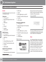
General information on infotainment......
Quick start...............................................
General infotainment functions...............
Radio.......................................................
Media player...........................................
External audio source via AUX/USB*
input........................................................
HomeLink *............................................ 140
226
228
233
236
243
247
Media Bluetooth* ................................. 250
TV*........................................................... 253
Remote control* ..................................... 256
Bluetooth handsfree*............................
Voice recognition* mobile phone............
RSE - Rear Seat Entertainment system*
Menu navigation, Infotainment...............
258
266
270
279
* Option/accessory, for more information, see Introduction.
5
Table of contents
06 07 08
06 During your journey
Recommendations during driving...........
Refuelling................................................
Fuel.........................................................
Loading...................................................
Cargo area..............................................
Driving with a trailer................................
Towing and recovery..............................
6
07 Wheels and tyres
286
289
290
294
298
301
307
General ...................................................
Changing wheels ...................................
Tyre pressure .........................................
Warning triangle and first-aid kit*............
Emergency puncture repair (TMK)* ........
* Option/accessory, for more information, see Introduction.
08 Maintenance and service
312
316
319
320
321
Engine compartment...............................
Lamps.....................................................
Wiper blades and washer fluid................
Battery.....................................................
Fuses......................................................
Car care..................................................
328
335
342
344
349
360
Table of contents
09 10
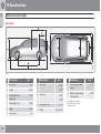
09 Specifications
Type designations...................................
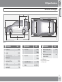
Dimensions and weights.........................
Engine specifications..............................
Engine oil................................................
Fluids and lubricants...............................
Fuel.........................................................
Wheel and tyres, dimensions and pressure ........................................................
Electrical system.....................................
Type approval.........................................
Symbols in the display............................
10 Alphabetical Index
368
370
376
378
381
383
Alphabetical Index.................................. 408
387
392
393
405
7
Introduction
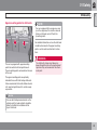
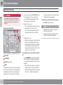
Important information
Reading the Owner's Manual
Introduction
A good way of getting to know your new car is
to read the owner's manual, ideally before your
first journey. This will give you the opportunity
to familiarise yourself with new functions, to
see how best to handle the car in different situations, and to make the best use of all the
car's features. Please pay attention to the
safety instructions contained in the manual.
The specifications, design features and illustrations in this owner's manual are not binding.
We reserve the right to make modifications
without prior notice.
©
In the event of uncertainty over what is standard or an option/accessory, contact a Volvo
dealer.
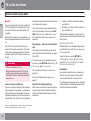
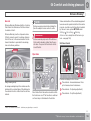
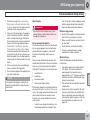
Special texts
WARNING
Warning texts advise of a risk of personal
injury.
IMPORTANT
Important texts advise of a risk of material
damage.
All types of option/accessory are marked with
an asterisk*.
In addition to standard equipment, this manual
also describes options (factory fitted equipment) and certain accessories (retrofitted extra
equipment).
The equipment described in the owner's manual is not available in all cars - they have different equipment depending on adaptations
for the needs of different markets and national
or local laws and regulations.
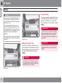
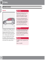
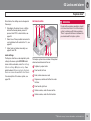
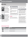
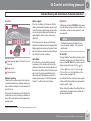
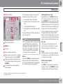
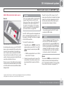
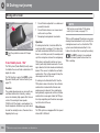
The car contains different types of decal which
are designed to convey important information
in a simple and clear manner. The decals in the
car have the following descending degree of
importance for the warning/information.
Warning for personal injury
NOTE texts give advice or tips that facilitate
the use of features and functions for example.
Footnote
There is footnote information in the owner's
manual that is located at the bottom of the
page. This information is an addition to the text
that it refers to via a number. If the footnote
refers to text in a table then letters are used
instead of numbers for referral.
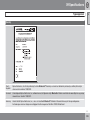
Message texts
There are displays in the car that show text
messages. These text messages are high-
8
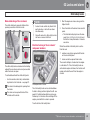
Decals
NOTE
Volvo Car Corporation
Option
lighted in the owner's manual by means of the
text being slightly larger and printed in grey.
Examples of this are in menu texts and message texts on the information display (e.g.
Audio settings).
* Option/accessory, for more information, see Introduction.
G031590
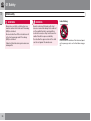
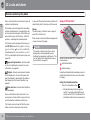
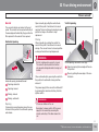
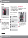
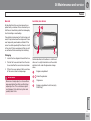
Black ISO symbols on yellow warning field,
white text/image on black message field. Used
to indicate the presence of danger which, if the
Introduction
Important information
warning is ignored, may result in serious personal injury or fatality.
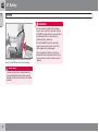
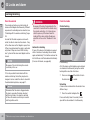
Information
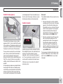
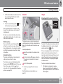
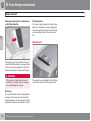
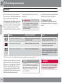
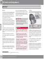
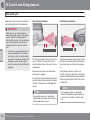
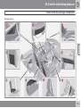
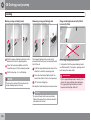
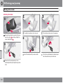
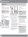
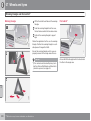
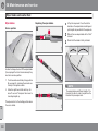
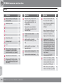
Procedure lists
Procedures where action must be taken in a
certain sequence are numbered in the owner's
manual.
Risk of property damage
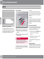
When there is a series of illustrations for
step-by-step instructions each step is
numbered in the same way as the corresponding illustration.
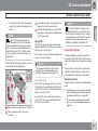
G031592
G031593
There are numbered lists with letters adjacent to the series of illustrations where the
order of the instructions is not significant.
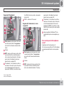
White ISO symbols and white text/image on
black or blue warning field and message field.
Used to indicate the presence of danger which,
if the warning is ignored, may result in damage
to property.
White ISO symbols and white text/image on
black message field.
NOTE
The labels shown in the owner's manual are
not provided as exact reproductions of
those in the car. The purpose is to show
their approximate appearance and location
in the car. The information that applies to
your car in particular is available on the label
in question in your car.
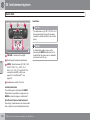
Arrows appear numbered and unnumbered and are used to illustrate a movement.
If there is no series of illustrations for step-bystep instructions then the different steps are
numbered with normal numbers.
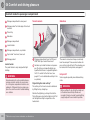
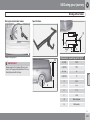
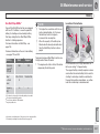
Position lists
Red circles containing a number are used
in overview images where different components are pointed out. The number
recurs in the position list featured in connection with the illustration that describes
the item.
Bulleted lists
A bulleted list is used when there is a list of
points in the owner's manual.
Example:
9
Introduction
Important information
• Coolant
• Engine oil
To be continued
`` This symbol is located furthest down to the
right when a section continues on the following
page.
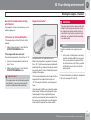
Recording data
Your vehicle contains a number of computers
whose function is to continuously check and
monitor the vehicle's operation and functionality. Some of the computers can record information during normal driving if they detect an
error. In addition, information is recorded in the
event of a crash or incident. Parts of the recorded information are required so that technicians can diagnose and rectify faults in the
vehicle during servicing and maintenance and
so that Volvo can fulfil legal requirements and
other regulations. In addition to this, the information is used for research purposes by Volvo
in order to continually develop quality and
safety, as the information can contribute to a
better understanding of the factors that cause
accidents and injuries. The information
includes details of the status and functionality
of various systems and modules in the vehicle
with regard to engine, throttle, steering and
brake systems, amongst other things. This
information may include details regarding the
10
way the driver drives the vehicle, such as vehicle speed, brake and accelerator pedal use,
steering wheel movement and whether or not
the driver and passengers have used their
seatbelts. For the reasons given this information may be stored in the vehicle's computers
for a certain length of time, but also as a result
of a collision or incident. This information may
be stored by Volvo as long as it can help to
further develop and further enhance safety and
quality and as long as there are legal requirements and other regulations that Volvo needs
to consider.
Volvo will not contribute to the above-described information being disclosed to third parties
without the vehicle owner's consent. However,
due to national legislation and regulations
Volvo may be required to disclose such information to authorities such as police authorities,
or others who may assert a legal right to have
access to it.
To be able to read and interpret the information
recorded by the computers in the vehicle
requires special technical equipment that
Volvo, and workshops that have entered into
agreements with Volvo, have access to. Volvo
is responsible that the information, which is
transferred to Volvo during servicing and maintenance, is stored and handled in a secure
manner and that the handling complies with
* Option/accessory, for more information, see Introduction.
applicable legal requirements. For further information - contact a Volvo dealer.
Accessories and extra equipment
The incorrect connection and installation of
accessories can negatively affect the car's
electrical system. Certain accessories only
function when their associated software is
installed in the car's computer system. Volvo
therefore recommends that you always contact an authorised Volvo workshop before
installing accessories which are connected to
or affect the electrical system.
Change of ownership for cars with
Volvo On Call*
Volvo On Call is a supplemental service that
consists of safety, security and comfort services. If the car has Volvo On Call and there is a
change of owner, it is very important that these
services are discontinued so that the former
owner cannot access the services in the car.
Contact the call centre by pressing the ON
CALL button in the car or contact an authorised Volvo workshop. See also "Changing the
security code" in the owner's manual for Volvo
On Call.
Introduction
Important information
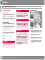
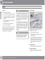
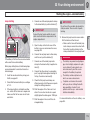
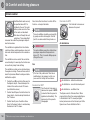
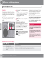
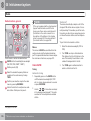
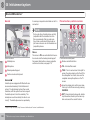
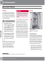
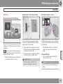
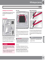
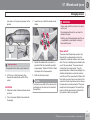
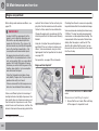
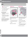
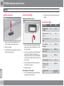
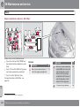
Laser sensor
This vehicle is equipped with a sensor which
transmits laser light. It is absolutely essential to
follow the prescribed instructions when handling the laser sensor.
The following two labels in English are fitted
directly on the laser sensor unit:
The upper label in the figure describes the laser
beam's classification:
• Laser radiation - Do not look into the laser
beam with optical instruments - Class 1M
laser product.
The lower label in the figure describes the laser
beam's physical data:
• IEC 60825-1:1993 + A2:2001. Complies
exception of deviations in accordance with
"Laser Notice No. 50" from 26 July 2001.
Radiation data for the laser sensor
The following table specifies the laser sensor's
physical data.
Maximum pulse energy
2.64 μJ
Maximum average output
45 mW
Pulse duration
33 ns
Divergence (horizontal x vertical)
28° × 12°
WARNING
If any of these instructions are not followed
then there is a risk of eye injury!
•
Never look into the laser sensor (which
emits spreading invisible laser radiation)
at a distance of 100 mm or closer with
magnifying optics such as a magnifying
glass, microscope, lens or similar optical instruments.
•
Testing, repair, removal, adjustment
and/or replacement of the laser sensor's spare parts must only be carried
out by a qualified workshop - we recommend an authorised Volvo workshop.
•
To avoid exposure to harmful radiation,
do not carry out any readjustments or
maintenance other than those specified
here.
•
The repairer must follow specially
drawn up workshop information for the
laser sensor.
•
Do not remove the laser sensor (this
includes removing the lenses). A
removed laser sensor does not fulfil
laser class 3B as per standard IEC
60825-1. Laser class 3B is not eye-safe
and therefore entails a risk of injury.
with FDA (U.S. Food Administration) standards for laser product design with the
11
Introduction
Important information
•
The laser sensor's connector must be
unplugged before removal from the
windscreen.
•
The laser sensor must be fitted onto the
windscreen before the sensor's connector is plugged in.
•
The laser sensor transmits laser light
when the remote control key is in position II and also with the engine switched
off (see page 82 on key positions).
For more information on the laser sensor, see
page 192.
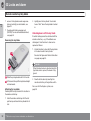
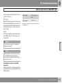
Information on the Internet
At www.volvocars.com there is further information concerning your car.
12
Introduction
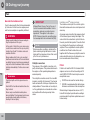
Volvo and the environment
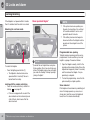
G000000
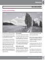
Volvo Cars' environmental philosophy
Environmental care is one of Volvo Car Corporation's core values which influence all operations. We also believe that our customers share
our consideration for the environment.
Your Volvo complies with strict international
environmental standards and is also manufactured in one of the cleanest and most resourceefficient plants in the world. Volvo Car Corporation has global ISO certification, which
includes the environmental standard ISO
14001 covering all factories and several of our
other units. We also set requirements for our
partners so that they work systematically with
environmental issues.
Fuel consumption
Volvo cars have competitive fuel consumption
in each of their respective classes. Lower fuel
consumption generally results in lower emission of the greenhouse gas, carbon dioxide.
It is possible for the driver to influence fuel consumption. For more information read under the
heading, Reducing environmental impact.
Efficient emission control
Your Volvo is manufactured following the concept "Clean inside and out" – a concept that
encompasses a clean interior environment as
well as highly efficient emission control. In
many cases the exhaust emissions are well
below the applicable standards.
Clean air in the passenger compartment
A passenger compartment filter prevents dust
and pollen from entering the passenger compartment via the air intake.
A sophisticated air quality system, IAQS* (Interior Air Quality System) ensures that the incoming air is cleaner than the air in the traffic outside.
The system consists of an electronic sensor
and a carbon filter. The incoming air is monitored continuously and if there is an increase in
* Option/accessory, for more information, see Introduction.
13
Introduction
Volvo and the environment
the level of certain unhealthy gases such as
carbon monoxide then the air intake is closed.
Such a situation may arise in heavy traffic,
queues and tunnels for example.
The entry of nitrous oxides, ground-level ozone
and hydrocarbons is prevented by the carbon
filter.
Interior
The interior of a Volvo is designed to be pleasant and comfortable, even for people with
contact allergies and for asthma sufferers.
Extreme attention has been given to choosing
environmentally-compatible materials.
Volvo workshops and the environment
Regular maintenance creates the conditions
for a long service life and low fuel consumption
for your car. In this way you contribute to a
cleaner environment. When Volvo's workshops
are entrusted with the service and maintenance of your car it becomes part of our system. Volvo makes clear demands regarding the
way in which our workshops are designed in
order to prevent spills and discharges into the
environment. Our workshop staff have the
knowledge and the tools required to guarantee
good environmental care.
Reducing environmental impact
You can easily help reduce environmental
impact - here are a few tips:
14
• Avoid letting the engine idle - switch off the
engine when stationary for longer periods.
Pay attention to local regulations.
• Drive economically - think ahead.
• Perform service and maintenance in
accordance with the owner's manual's
instructions - follow the Service and Warranty Booklet's recommended intervals.
Recycling
As a part of Volvo's environmental work, it is
important that the car is recycled in an environmentally sound manner. Almost all of the
car can be recycled. The last owner of the car
is therefore requested to contact a dealer for
referral to a certified/approved recycling
facility.
• If the car is equipped with an engine block
heater*, use it before starting from cold - it
improves starting capacity and reduces
wear in cold weather and the engine reaches normal operating temperature more
quickly, which lowers consumption and
reduces emissions.
• High speed increases consumption considerably due to increased wind resistance
- a doubling of speed increases wind resistance 4 times.
• Always dispose of environmentally hazardous waste, such as batteries and oils, in
an environmentally safe manner. Consult a
workshop in the event of uncertainty about
how this type of waste should be discarded
- an authorised Volvo workshop is recommended.
Following this advice can save money, the
planet's resources are saved, and the car's
durability is extended. For more information
and further advice, see the pages 286 and
386.
* Option/accessory, for more information, see Introduction.
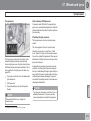
The owner's manual and the
environment
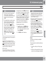
The FSC symbol shows that the paper pulp in
this publication comes from FSC certified forests or other controlled sources.
Introduction
15
Seatbelts ................................................................................................
Airbags....................................................................................................
Activating/deactivating the airbag*.........................................................
Side airbags (SIPS bags) .......................................................................
Inflatable Curtain (IC) .............................................................................
WHIPS ....................................................................................................
When the systems deploy ......................................................................
Safety mode............................................................................................
Child safety.............................................................................................
16
* Option/accessory, for more information, see Introduction.
18
21
24
26
28
29
31
32
33
SAFETY
01 Safety
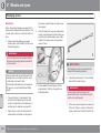
Seatbelts
01
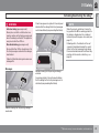
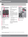
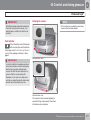
General information
Releasing the seatbelt
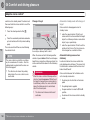
Press the red button on the seatbelt buckle and
then let the belt retract. If the seatbelt does not
retract fully, feed it in by hand so that it does
not hang loose.
The seatbelt locks and cannot be withdrawn:
• if it is pulled out too quickly
• during braking and acceleration
• if the car leans heavily.
Make sure that you:
Heavy braking can have serious consequences
if the seatbelts are not used. Ensure that all
passengers use their seatbelts.
It is important that the seatbelt lies against the
body so it can provide maximum protection.
Do not lean the backrest too far back. The
seatbelt is designed to protect in a normal
seating position.
• do not use clips or anything else that can
prevent the seatbelt from fitting properly
• ensure that the seatbelt is not twisted or
caught on anything
• the hip strap must be positioned low down
(not over the abdomen)
• tension the hip strap over the lap by pulling
the diagonal shoulder belt up towards the
shoulder.
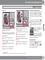
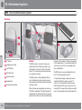
Putting on a seatbelt
Pull the belt out slowly and secure it by pressing its locking tab into the seatbelt buckle. A
loud "click" indicates that the belt has locked.
The buckles only fit the intended lock in the rear
seat1.
1
18
Certain markets.
WARNING
The seatbelts and airbags interact. If a seatbelt is not used or is used incorrectly, this
may diminish the protection provided by the
airbag in the event of a collision.
WARNING
Each seatbelt is designed for only one person.
WARNING
Never modify or repair the seatbelts yourself. Volvo recommends that you contact an
authorised Volvo workshop.
If a seatbelt has been subjected to a major
load, such as in conjunction with a collision,
the entire seatbelt must be replaced. Some
of the protective characteristics of the seatbelt may have been lost, even if it appears
to be undamaged. In addition, replace the
seatbelt if the belt is worn or damaged. The
new seatbelt must be type-approved and
intended for installation in the same position
as the replaced seatbelt.
01 Safety
Seatbelts
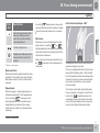
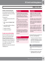
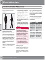
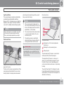
Seatbelts and pregnancy
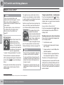
and steering wheel). The aim should be to position the seat with as large a distance as possible between abdomen and steering wheel.
The seatbelt reminder in the rear seat has two
subfunctions:
are being used in the rear seat. A message
appears in the information display when
the seatbelts are in use, or if one of the rear
doors has been opened. The message is
cleared automatically after driving for
approximately 30 seconds or after pressing the indicator stalk's READ button.
G020998
The lap section should lay flat over the thighs
and as low as possible under the abdomen. –
It must never be allowed to ride upward.
Remove the slack from the seatbelt and ensure
that it fits as close to the body as possible. In
addition, check that there are no twists in the
seatbelt.
Rear seat
• Provides information on which seatbelts
Seatbelt reminder
• Provides a warning if one of the rear seat-
G017726
The seatbelt should always be worn during
pregnancy. But it is then crucial that it be worn
in the correct way. The diagonal section should
wrap over the shoulder then be routed between
the breasts and to the side of the abdomen.
01
Unbelted occupants will be reminded to fasten
their seatbelts by means of an audio and visual
reminder. The audio reminder is speed
dependent, and in some cases time dependent. The visual reminder is located in the roof
console and the combined instrument panel.
belts is unfastened during travel. This
warning takes the form of a message on
the information display along with the
audio/visual signal. The warning stops
when the seatbelt is re-fastened, or it can
also be acknowledged manually by pressing the READ button.
The message on the information display showing which seatbelts are in use is always available. Press the READ button to see stored
messages.
Child seats are not covered by the seatbelt
reminder system.
As the pregnancy progresses, pregnant drivers
should adjust their seats and steering wheel
such that they can easily maintain control of the
vehicle as they drive (which means that they
must be able to easily operate the foot pedals
``
19
01 Safety
01
Seatbelts
Certain markets
An acoustic signal and indicator lamp remind
the driver and front seat passenger to use a
seatbelt if either of them is not wearing one. At
low speed, the audio reminder will sound for
the first 6 seconds.
Seatbelt tensioner
All the seatbelts are equipped with belt tensioners. A mechanism in the seatbelt tensioner
tightens the seatbelt in the event of a sufficiently violent collision. The seatbelt then provides more effective restraint for the occupants.
WARNING
Never insert the tongue of the passenger's
seatbelt into the buckle on the driver's side.
Always insert the tongue of the seatbelt into
the buckle on the correct side. Do not make
any damages on seatbelts nor insert any
foreign objects into a buckle. The seatbelts
and buckles would then possibly not function as intended in the event of a collision.
There is a risk of serous injury.
20
01 Safety
Airbags
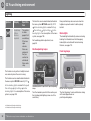
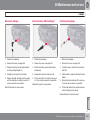
Warning symbol on the combined
instrument panel
01
As well as the warning symbol, a message may
appear on the information display in appropriate cases. If the warning symbol malfunctions,
the warning triangle illuminates and SRS
Airbag Service required or SRS Airbag
Service urgent appears in the display. Volvo
recommends that you contact an authorised
Volvo workshop immediately.
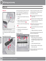
G018666
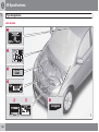
Airbag system
Airbag system, right-hand drive car.
G018665
The warning symbol in the combined instrument panel illuminates when the remote control key is in key position II or III. The symbol
clears after approx. 6 seconds provided the
airbag system is fault-free.
WARNING
If the warning symbol for the airbag system
remains illuminated or illuminates while driving, it means that the airbag system does
not have full functionality. The symbol indicates a fault in the seatbelt tensioner system, SIPS, the IC system or some other fault
in the system. Volvo recommends that you
contact an authorised Volvo workshop
immediately.
The system consists of airbags and sensors. A
sufficiently violent collision trips the sensors
and the airbag(s) are inflated with hot gas. To
cushion the impact, the airbag deflates when
compressed. When this occurs, smoke
escapes into the car. This is completely normal. The entire process, including inflation and
deflation of the airbag, occurs within tenths of
a second.
Airbag system, left-hand drive car.
WARNING
Volvo recommends that you contact an
authorised Volvo workshop for repair.
Defective work in the airbag system could
cause malfunction and result in serious personal injury.
``
21
01 Safety
01
Airbags
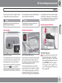
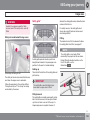
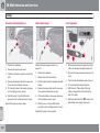
Passenger airbag
NOTE
The car has an airbag to supplement the protection afforded by the seatbelt on the passenger side. It is folded up into a compartment
above the glovebox. Its cover panel is marked
AIRBAG.
The sensors react differently depending on
the course of the collision and whether or
not the seatbelts on the driver and passenger side are used.
It is therefore possible that only one (or
none) of the airbags may inflate in a collision. The airbag system senses the force of
the collision on the car and adapts accordingly so that one or more airbags are
deployed.
The capacity of the airbags is also adapted
to the collision force to which the vehicle is
subjected.
WARNING
Location of the front passenger airbag in a righthand drive car.
Airbag on the driver's side
The car has an airbag to supplement the protection afforded by the seatbelt on the driver's
side. It is folded up into the centre of the steering wheel. The steering wheel is marked
AIRBAG.
WARNING
The seatbelts and airbags interact. If a seatbelt is not used or is used incorrectly, this
may diminish the protection provided by the
airbag in the event of a collision.
Location of the front passenger airbag in a lefthand drive car.
22
To minimise the risk of injury if the airbag
deploys, passengers must sit as upright as
possible with their feet on the floor and
backs against the backrest. Seatbelts must
be secured.
WARNING
Do not put objects in front of or above the
dashboard where the passenger airbag is
located.
01 Safety
Airbags
01
WARNING
Never place a child in a child seat or on a
booster cushion in the front seat if the airbag
is activated.
Never allow anybody to stand or sit in front
of the front passenger seat.
No one shorter than 140 cm should ever sit
in the front passenger seat if the airbag is
activated.
Failure to follow the advice given above can
endanger life.
23
01 Safety
01
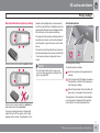
Activating/deactivating the airbag*
Key switch off - PACOS*
General information
The airbag for the front passenger seat can be
deactivated if the car is equipped with a switch,
PACOS (Passenger Airbag Cut Off Switch). For
information on how to activate/deactivate, see
under the heading Activating/deactivating.
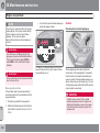
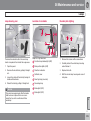
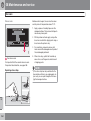
Key switch off/switch
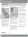
The switch for the passenger airbag (PACOS)
is located on the passenger end of the instrument panel and is accessible when the passenger door is open (see under the heading
below, Activating/deactivating).
Check that the switch is in the required position. Volvo recommends that the remote control key's key blade be used to change position.
For information on the key blade, see
page 51.
WARNING
Failure to follow the advice given above
could endanger the life of passengers in the
car.
24
WARNING
Activating/deactivating
If the car is equipped with a front passenger
airbag, but does not have a PACOS switch
(Passenger Airbag Cut Off Switch), then the
airbag will always be activated.
WARNING
Never place a child in a child seat or on a
booster cushion in the front seat if the airbag
is activated and the symbol
in the roof
console is illuminated. Failure to follow this
advice could endanger the life of the child.
Switch location
WARNING
Do not allow anyone to sit in the front passenger seat if the message in the roof panel
(see page 25) indicates that the airbag is
deactivated and if the warning symbol for
the airbag system is also displayed in the
combined instrument panel. This indicates
that there has been a severe malfunction.
Visit a workshop as soon as possible. Volvo
recommends that you contact an authorised Volvo workshop.
* Option/accessory, for more information, see Introduction.
The airbag is activated. With the switch in
this position, persons taller than 140 cm
can sit in the front passenger seat, but
never children in a child seat or on a
booster cushion.
The airbag is deactivated. With the switch
in this position, children in a child seat or
on a booster cushion can sit in the front
passenger seat, but never persons taller
than 140 cm.
01 Safety
Activating/deactivating the airbag*
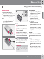
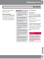
A text message and a symbol in the roof panel
indicate that the airbag for the front passenger
seat is deactivated (see preceding illustration).
WARNING
Activated airbag (passenger seat):
Never place a child in a child seat or on a
booster cushion on the front passenger seat
when the airbag is activated. This applies to
everyone shorter than 140 cm.
01
NOTE
When the remote control key is turned to
key position II or III the warning symbol for
the airbag is displayed on the combined
instrument panel for approx. 6 seconds (see
page 21).
Following which, the indicator in the roof
console is illuminated showing the correct
status for the front passenger seat airbag.
For more information about the different key
positions for the remote control key, see
page 82.
Deactivated airbag (passenger seat):
No one taller than 140 cm should ever sit in
the front passenger seat when the airbag is
deactivated.
G017800
Failure to follow the advice given above can
endanger life.
Messages
Indicator showing that the passenger airbag is
activated.
A warning symbol in the roof panel indicates
that the airbag for the front passenger seat is
activated (see preceding illustration).
2
G017724
2
Indicator showing that the passenger airbag is
deactivated.
* Option/accessory, for more information, see Introduction.
25
01 Safety
Side airbags (SIPS bags)
G032949
WARNING
In a side impact collision a large proportion of
the collision force is transferred by the SIPS
(Side Impact Protection System) to beams, pillars, the floor, the roof and other structural
parts of the body. The side airbags at the driver's and front passenger seats protect the
chest area and the hip and are an important
part of the SIPS.
The SIPS bag system consists of two main
components, side airbag and sensors. The
side airbags are located in the front seat backrests.
•
Volvo recommends that repairs are only
carried out by an authorised Volvo
workshop. Defective work in the SIPSbag system could cause malfunction
and result in serious personal injury.
•
Do not put objects in the area between
the outside of the seat and the door
panel, since this area is required by the
side airbag.
•
Volvo recommends the use only of car
seat covers approved by Volvo. Other
seat covers may impede the operation
of the side airbags.
•
Location
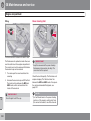
G024377
Side airbag
Driver's seat, left-hand drive.
The side airbag is a supplement to the
seatbelts. Always use a seatbelt.
Child seats and side airbags
The protection provided by the car to children
seated in a child seat or on a booster cushion
is not diminished by the side airbag.
A child seat or booster cushion can be placed
on the front passenger seat provided that the
car does not have an activated1 passenger airbag.
G024378
01
Front passenger seat, left-hand drive.
The SIPS bag system consists of side airbags
and sensors. A sufficiently violent collision trips
1
26
For information on activating/deactivating the airbag, see page 24.
01 Safety
Side airbags (SIPS bags)
01
the sensors and the side airbags are inflated.
The airbag inflates between the occupant and
the door panel and thereby cushions the initial
impact. The airbag deflates when compressed
by the collision. The side airbag is normally only
deployed on the side of the collision.
27
01 Safety
01
Inflatable Curtain (IC)
Properties
WARNING
Never hang or attach heavy items onto the
handles in the roof. The hook is only
designed for light clothing (not for solid
objects such as umbrellas for example).
Do not screw or install anything onto the
car's headlining, door pillars or side panels.
This could compromise the intended protection. Volvo recommends that you only
ever use Volvo genuine parts that are
approved for placement in these areas.
WARNING
The inflatable curtain IC (Inflatable Curtain) is a
part of SIPS and the airbags. It is fitted in the
headlining along both sides of the roof and
protects the car's occupants sitting in the outer
seats. A sufficiently violent collision trips the
sensors and the inflatable curtain is inflated.
The inflatable curtain helps to prevent the
driver and passengers from striking their heads
on the inside of the car during a collision.
Do not load the car higher than 50 mm under
the top edge of the door windows. Otherwise, the intended protection of the inflatable curtain, which is concealed in the headlining, may be compromised.
WARNING
The inflatable curtain is a supplement to the
seatbelts.
Always use a seatbelt.
28
01 Safety
WHIPS
Protection against whiplash injury –
WHIPS
The whiplash protection system (WHIPS) consists of energy absorbing backrests and specially designed head restraints in the front
seats. The system is actuated by a rear-end
collision, where the angle and speed of the collision, and the nature of the colliding vehicle all
have an influence.
01
Correct seating position
For the best possible protection, the driver and
front seat passenger should sit in the centre of
the seat with as little space as possible
between the head and the head restraint.
Do not obstruct the WHIPS system
WARNING
The WHIPS system is a supplement to the
seatbelts. Always use a seatbelt.
Properties of the seat
When the WHIPS system is deployed, the front
seat backrests are lowered backward to alter
the seating position of the driver and front seat
passenger. This reduces the risk of whiplash
injury.
WARNING
Never modify or repair the seat or WHIPS
system yourself. Volvo recommends that
you contact an authorised Volvo workshop.
WHIPS system and child seats/booster
cushions
Do not leave any objects on the floor behind the
driver's seat/passenger seat that may prevent the
WHIPS system from functioning.
WARNING
Do not squeeze rigid objects between the
rear seat cushion and the front seat backrest. Make sure you do not to obstruct the
function of the WHIPS system.
The protection provided by the car to children
seated in a child seat or on a booster cushion
is not diminished by the WHIPS system.
``
29
01 Safety
01
WHIPS
WARNING
If a seat has been subjected to extreme
forces, such as due to a rear-end collision,
the WHIPS system must be checked. Volvo
recommends that it is checked by an
authorised Volvo workshop.
Part of the WHIPS system's protective
capacity may have been lost even if the
seats appear to be undamaged.
Do not place objects on the rear seat that may
prevent the WHIPS system from functioning.
WARNING
If a rear seat backrest is folded down, the
corresponding front seat must be moved
forward so that it does not touch the folded
backrest.
30
Volvo recommends that you contact an
authorised Volvo workshop to have the system checked even after a minor rear-end
collision.
01 Safety
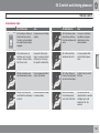
When the systems deploy
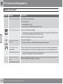
When the systems deploy
System
Triggered
Seatbelt tensioner,
front seat
In a frontal collision
and/or side-impact
accident and/or
rear-end collision
Seatbelt tensioner,
rear seat
A
In a frontal collision
Airbags (SRS)
In a frontal collisionA
Side airbags (SIPS)
In a side-impact
accidentA
Inflatable Curtain IC
In a side-impact
accidentA
Whiplash protection
WHIPS
In a rear-end collision
The bodywork of the car could be greatly deformed in a collision without airbag deployment. A number of factors such
as the rigidity and weight of the object hit, the speed of the
car, the angle of the collision etc. affects how the different
safety systems of the car are activated.
Volvo workshop. Do not drive with
deployed airbags.
• Volvo recommends that you engage an
authorised Volvo workshop to handle the
replacement of components in the car's
safety systems.
• Always contact a doctor.
NOTE
01
WARNING
Never drive with deployed airbags. They
can make steering difficult. Other safety
systems may also be damaged. The smoke
and dust created when the airbags are
deployed can cause skin and eye irritation/
injury after intensive exposure. In case of
irritation, wash with cold water. The rapid
deployment sequence and airbag fabric
may cause friction and skin burns.
The SRS, SIPS, IC and belt tensioner systems are deployed only once during a collision.
WARNING
The airbag control module is located in the
centre console. If the centre console is
drenched with water or other liquid, disconnect the battery cables. Do not attempt to
start the car since the airbags may deploy.
Recovering the car. Volvo recommends that
you have it conveyed to an authorised Volvo
workshop.
If the airbags have deployed, the following is
recommended:
• Recovering the car. Volvo recommends
that you have it conveyed to an authorised
31
01 Safety
01
Safety mode
Driving after a collision
effect that the ignition is on, press the start
button. Then close the door and reinsert the
remote control key. The car's electronics will
now try to reset themselves to normal mode.
Then try to start the car.
If the message Safety mode See manual is
still shown on the display then the car must not
be driven or towed, but a vehicle recovery service used instead. Even if the car appears to be
driveable, hidden damage may make the car
impossible to control once moving.
If the car is involved in a collision, the text
Safety mode See manual may appear on the
information display. This means that the car
has reduced functionality. Safety mode is a
protective state that is enforced when the collision may have damaged any of the car's vital
functions, such as the fuel lines, sensors for
one of the safety systems, or the brake system.
Attempting to start the car
First, check that no fuel is leaking from the car.
There must be no smell of fuel either.
If everything seems normal and you have
checked for indications of fuel leakage, you
may attempt to start the car.
Remove the remote control key and open the
driver's door. If a message is now shown to the
32
Moving the car
If Normal mode is shown after Safety mode
See manual has been reset, the car can be
moved carefully out of a dangerous position.
Do not move the car further than necessary.
WARNING
Never attempt to repair your car or reset the
electronics yourself if the car has been in
safety mode. This could result in personal
injury or the car not functioning as normal.
Volvo recommends that you engage an
authorised Volvo workshop to check and
restore the car to normal status after Safety
mode See manual has been displayed.
WARNING
Never, under any circumstances, attempt to
restart the car if it smells of fuel when the
Safety mode See manual message is displayed. Leave the car at once.
WARNING
If the car is in safety mode it must not be
towed. It must be transported from its location. Volvo recommends that it is transported to an authorised Volvo workshop.
01 Safety
Child safety
Children should sit comfortably and
safely
Volvo recommends that children travel in rearfacing child seats until as late an age as possible, at least until 3-4 years of age, and then
front-facing booster cushions/child seats until
up to 10 years of age.
beams under the seat. Sharp edges can damage the straps.
NOTE
In the event of questions when fitting child
safety products, contact the manufacturer
for clearer instructions.
Look in the installation instructions for the child
seat for the correct fitting.
Location of child seats
Child seats
You may place:
The position of a child in the car and the choice
of equipment are dictated by the child's weight
and size, for more information, see page 35.
• a child seat/booster cushion on the passenger seat, provided the passenger airbag is not activated1.
• one or more child seats/booster cushions
NOTE
in the rear seat.
Volvo has child safety equipment (child seats,
booster cushions & attachment devices) which
is designed for your particular car. Using Volvo's child safety equipment provides you with
optimum conditions for your child to travel
safely in the car. Furthermore, the child safety
equipment fits and is easy to use.
1
G020739
Regulations regarding the placement of
children in cars vary from country to country. Check what does apply.
Children of all ages and sizes must always sit
correctly secured in the car. Never allow a child
to sit on the knee of a passenger.
01
Always fit child seats/booster cushions in the
rear seat if the passenger airbag is activated. If
a child is sitting on the front passenger seat
then he/she could suffer serious injury if the
airbag deploys.
Child seats and airbags are not compatible.
NOTE
When using child safety products it is
important to read the installation instructions included.
Do not attach the straps for the child seat to
the horizontal adjustment bar, springs, rails or
For information on activated/deactivated airbag, see page 24.
``
33
01 Safety
01
Child safety
WARNING
Never place a child in a child seat or on a
booster cushion in the front seat if the airbag
(SRS) is activated.
No one shorter than 140 cm should ever sit
in the front passenger seat if the airbag
(SRS) is activated.
Failure to follow the advice given above can
endanger life.
34
WARNING
Label Airbag
Booster cushions/child seats with steel
braces or some other design that could rest
on the seatbelt buckle's opening button
must not be used, as they could cause the
seatbelt buckle to open accidentally.
Do not allow the upper section of the child
seat to rest against the windscreen.
Label fitted on the end face of the instrument panel
on the passenger side, see the illustration on page
24.
01 Safety
Child safety
01
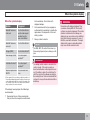
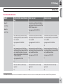
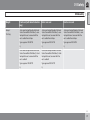
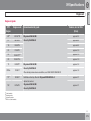
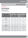
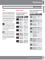
Recommended child seats2
Weight
Front seat (with deactivated airbag)
Group 0
Outer rear seat
Centre rear seat
Volvo infant seat (Volvo Infant Seat) rear-facing child seat, secured with the
ISOFIX fixture system.
max 10 kg
Group 0+
Type approval: E5 03301146
max 13 kg
(L)
Volvo infant seat (Volvo Infant Seat) rear-facing child seat, secured with the
car's seatbelt.
Volvo infant seat (Volvo Infant Seat) rear-facing child seat, secured with the
car's seatbelt.
Volvo infant seat (Volvo Infant Seat) rear-facing child seat, secured with the
car's seatbelt.
Type approval: E1 04301146
Type approval: E1 03301146
Type approval: E1 03301146
(U)
(U)
(U)
Rear-facing child seat (Child Seat) rear-facing child seat, secured with the
car's seatbelt and straps. Use a protective cushion between the child seat
and the dashboard.
Rear-facing child seat (Child Seat) rear-facing child seat, secured with the
car's seatbelt and straps.
Rear-facing child seat (Child Seat) rear-facing child seat, secured with the
car's seatbelt and straps.
Type approval: E5 03135
Type approval: E5 03135
(L)
(L)
Child seats which are universally
approved.
Child seats which are universally
approved.
Child seats which are universally
approved.
(U)
(U)
(U)
Type approval: E5 03135
(L)
2
With regard to other child seats your car should be included in the manufacturer's enclosed list of vehicles or be universally approved in accordance with the ECE R44 legal requirement.
``
35
01 Safety
01
Child safety
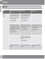
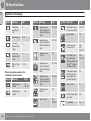
Weight
Front seat (with deactivated airbag)
Outer rear seat
Group 1
Volvo rear-facing/turnable child seat
(Volvo Convertible Child Seat) - rearfacing child seat, secured with the
car's seatbelt and straps.
Volvo rear-facing/turnable child seat
(Volvo Convertible Child Seat) - rearfacing child seat, secured with the
car's seatbelt and straps.
Type approval: E5 04192
Type approval: E5 04192
(L)
(L)
Rear-facing child seat (Child Seat) rear-facing child seat, secured with the
car's seatbelt and straps. Use a protective cushion between the child seat
and the dashboard.
Rear-facing child seat (Child Seat) rear-facing child seat, secured with the
car's seatbelt and straps.
Rear-facing child seat (Child Seat) rear-facing child seat, secured with the
car's seatbelt and straps.
Type approval: E5 03135
Type approval: E5 03135
(L)
(L)
9-18 kg
Type approval: E5 03135
Centre rear seat
(L)
Britax Fixway – rear-facing child seat,
secured with the ISOFIX fixture system
and straps.
Type approval: E5 03171
(L)
36
Child seats which are universally
approved.
Child seats which are universally
approved.
Child seats which are universally
approved.
(U)
(U)
(U)
01 Safety
Child safety
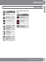
Weight
Front seat (with deactivated airbag)
Outer rear seat
Centre rear seat
Group 2
Volvo rear-facing/turnable child seat
(Volvo Convertible Child Seat) - rearfacing child seat, secured with the
car's seatbelt and straps
Volvo rear-facing/turnable child seat
(Volvo Convertible Child Seat) - rearfacing child seat, secured with the
car's seatbelt and straps
Volvo rear-facing/turnable child seat
(Volvo Convertible Child Seat) - rearfacing child seat, secured with the
car's seatbelt and straps
Type approval: E5 04192
Type approval: E5 04192
Type approval: E5 04192
(L)
(L)
(L)
Volvo rear-facing/turnable child seat
(Volvo Convertible Child Seat) - frontfacing child seat, secured with the
car's seatbelt.
Volvo rear-facing/turnable child seat
(Volvo Convertible Child Seat) - frontfacing child seat, secured with the
car's seatbelt.
Type approval: E5 04191
Type approval: E5 04191
(L)
(L)
15-25 kg
01
``
37
01 Safety
01
Child safety
Weight
Front seat (with deactivated airbag)
Outer rear seat
Centre rear seat
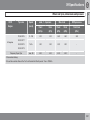
Group 2/3
Volvo booster seat with backrest
(Volvo Booster Seat with backrest).
Volvo booster seat with backrest
(Volvo Booster Seat with backrest).
Volvo booster seat with backrest
(Volvo Booster Seat with backrest).
Type approval: E1 04301169
Type approval: E1 04301169
Type approval: E1 04301169
(UF)
(UF)
(UF)
Booster cushion with and without
backrest (Booster Cushion with and
without backrest).
Booster cushion with and without
backrest (Booster Cushion with and
without backrest).
Booster cushion with and without
backrest (Booster Cushion with and
without backrest).
Type approval: E5 03139
Type approval: E5 03139
Type approval: E5 03139
(UF)
(UF)
(UF)
15-36 kg
Integrated booster cushion (Integrated
Booster Cushion) - available as a factory fitted option.
Type approval: E5 03168
(B)
L: Suitable for specific child seats. These child seats may be intended for use in a special car model, limited or semi-universal categories.
U: Suitable for universally approved child seats in this weight class.
UF: Suitable for front-facing universally approved child seats in this weight class.
B: Built-in child seats approved for this weight class.
38
01 Safety
Child safety
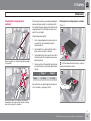
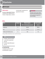
Integrated two-stage booster
cushions*
The booster cushions are specially designed to
provide optimum safety. In combination with
the seatbelt they are approved for children who
weigh between 15 and 36 kg and who are at
least 95 cm in height.
01
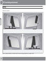
Raising the two-stage booster cushion
Stage 1
Check before driving that:
• the 2-stage integrated booster cushion is
correctly set (see table below) and in
locked position
• the seatbelt is in contact with the child's
G017875
body and is not slack or twisted
Correct position, the seatbelt is positioned above
the shoulder.
• the seatbelt does not lie across the child's
throat or below the shoulder (see preceding illustrations)
• the lap section of the seatbelt is positioned
low over the pelvis to provide optimal protection.
Weight
Stage 1
Stage 2
22-36 kg
15-25 kg
Pull the handle forward and up in order to
release the booster cushion.
Incorrect position, the head must not be positioned above the head restraint and the seatbelt
must not be below the shoulder.
G017697
G017719
For instructions on adjusting the booster cushion's two levels, see pages 39–40.
``
* Option/accessory, for more information, see Introduction.
39
01 Safety
01
Child safety
Press the booster cushion backwards to
lock.
Stage 2
Lift the booster cushion up at the front edge
and press it back against the backrest to lock.
WARNING
Volvo recommends that repair or replacement is only carried out by an authorised
Volvo workshop. Do not make any modifications or additions to the booster cushion.
If an integrated booster cushion has been
subjected to a major load, such as in conjunction with a collision, the entire booster
cushion must be replaced. Even if the
booster cushion appears to be undamaged,
it may not afford the same level of protection. The booster cushion must also be
replaced if it is heavily worn.
Start from the lower stage. Press the button.
NOTE
It is not possible to adjust the booster cushion from stage 2 to stage 1. It must first be
reset by being fully folded into the seat
cushion. Refer to the heading below, Lowering the two-stage booster cushion.
Lowering the two-stage booster cushion
G017784
Lowering can take place from both the upper
and lower stage to fully lowered position in the
cushion. However, it is not possible to adjust
40
the booster cushion from the upper stage to
the lower stage.
Pull the handle forwards to release the
cushion.
01 Safety
Child safety
Press down with your hand in the centre of
the cushion in order to lock it.
ISOFIX fixture system for child seats
WARNING
If the instructions regarding the two-stage
booster cushion are not followed then this
could cause serious injury to a child in the
event of an accident.
Check that there are no loose objects (e.g.
toys) left behind in the space under the
cushion before lowering.
NOTE
The booster cushion must be lowered first
when lowering the backrest.
Child safety locks, rear doors
The controls for operating the rear door power
windows and the rear door opening handles
can be blocked from opening from the inside.
For more information, see page 65.
Consequently, there is a size classification for
child seats using the ISOFIX fixture system in
order to assist users in choosing the correct
child seat (see the following table).
Size
class
IMPORTANT
Mounting points for the ISOFIX fixture system
are concealed behind the lower section of the
rear seat backrest, in the outer seats.
The location of the mounting points is indicated
by symbols in the backrest upholstery (see preceding illustration).
Press the seat cushion down to access the
mounting points.
Always follow the manufacturer's installation
instructions when connecting a child seat to
the ISOFIX mounting points.
Size classes
01
Description
A
Full size, front-facing child
seat
B
Reduced size (alt. 1), frontfacing child seat
B1
Reduced size (alt.2), frontfacing child seat
C
Full size, rear-facing child
seat
D
Reduced size, rear-facing
child seat
E
Rear-facing infant seat
F
Transverse infant seat, lefthand
G
Transverse infant seat, righthand
Child seats are in different sizes – cars are in
different sizes. This means that not all child
seats are suitable for all seats in all car models.
``
41
01 Safety
01
Child safety
NOTE
WARNING
Never place a child in the passenger seat if
the car is equipped with an activated airbag.
Volvo recommends that you contact an
authorised Volvo dealer for recommendations about which ISOFIX child seats Volvo
recommends.
NOTE
If an ISOFIX child seat has no size classification then the car model must be included
on the child seat's vehicle list.
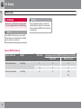
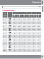
Types of ISOFIX child seat
Type of child seat
Infant seat transverse
Infant seat, rear-facing
Weight
max 10 kg
max 10 kg
Size class
Passenger seats for ISOFIX installation of child seats
Front seat
Outer rear seat
F
X
X
G
X
X
E
X
OK
(IL)
42
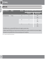
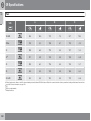
01 Safety
Child safety
Type of child seat
Infant seat, rear-facing
Weight
max 13 kg
Size class
E
01
Passenger seats for ISOFIX installation of child seats
Front seat
Outer rear seat
X
OK
(IL)
D
X
OK
(IL)
C
X
OK
(IL)
Child seat, rear-facing
9-18 kg
D
X
OK
(IL)
C
X
OK
(IL)
``
43
01 Safety
Child safety
01
Type of child seat
Front-facing child seat
Weight
9-18 kg
Size class
Passenger seats for ISOFIX installation of child seats
Front seat
Outer rear seat
X
OKA
B
(IUL)
B1
X
OKA
(IUL)
A
X
OKA
(IUL)
X: The ISOFIX position is not suitable for ISOFIX child seats in this weight class and/or size class.
IL: Suitable for specific ISOFIX child seats. These child seats may be intended for use in a special car model, limited or semi-universal categories.
IUF: Suitable for front-facing ISOFIX child seats that are universally approved in this weight class.
A
44
Volvo recommends rear-facing child seats for this group.
01 Safety
Child safety
Upper mounting points for child seats
01
NOTE
For cars equipped with a cargo area cover
over the cargo area, this must be removed
before a child seat can be fitted in the
mounting points.
For detailed information on how the child seat
should be tensioned in the upper mounting
points, see the seat manufacturer's instructions.
WARNING
The car is equipped with upper mounting
points for certain front-facing child seats.
These mounting points are located on the rear
of the seat.
The child seat's straps must always be
drawn through the hole in the head restraint
leg before they are tensioned at the attachment point.
The upper mounting points are primarily
intended for use with front-facing child seats.
Volvo recommends that small children should
sit in rear-facing child seats to as late an age
as possible.
NOTE
For cars with folding head restraints on the
outside seats the head restraints should be
folded to facilitate the installation of this
type of child seat.
45
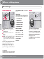
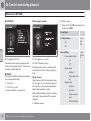
Remote control key/key blade................................................................
Privacy locking*.......................................................................................
Battery replacement, remote control key/PCC*......................................
Keyless drive*..........................................................................................
Locking/unlocking...................................................................................
Child safety locks....................................................................................
Alarm*......................................................................................................
46
* Option/accessory, for more information, see Introduction.
48
53
55
57
60
65
66
LOCKS AND ALARM
02 Locks and alarm
Remote control key/key blade
General
02
The car is supplied with 2 remote control keys
or PCCs (Personal Car Communicator). They
are used to start the car and for locking and
unlocking.
More remote control keys can be ordered – up
to 6 can be programmed and used for the same
car.
The PCC has increased functionality compared with the remote control key. The continuation of this chapter describes the functions
available in both the PCC and the remote control key.
WARNING
If there are children in the car:
Always remember to switch off the power
supply to power windows and sunroof by
removing the remote control key if the driver
leaves the car.
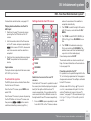
• Locking - one flash and the door mirrors
The current number of keys registered to the
car can be checked in the menu system MY
CAR under Information Number of keys.
For a description of the menu system, see
page 148.
• Unlocking - two flashes and the door mir-
Key memory1 – door mirrors and driver's
seat
The settings are automatically connected to
each respective remote control key, see pages
85 and 105.
The function can be activated/deactivated in
the menu system MY CAR under Settings
Car settings Car key memory.
For a description of the menu system, see
page 148.
For cars with Keyless drive system, see
page 57.
Loss of a remote control key
Indicator for locking/unlocking
If you lose a remote control key then new ones
can be ordered at a workshop - an authorised
Volvo workshop is recommended. The remaining remote control keys must then be taken to
the workshop. The code of the missing remote
When the car is locked or unlocked using the
remote control key, the direction indicators
confirm that locking/unlocking was correctly
performed.
1
2
48
control key must be erased from the system as
a theft prevention measure.
Only in combination with power driver's seat and power mirrors.
Only for cars with retractable power door mirrors.
are folded2 in.
rors are folded2 out.
After locking the indication is only given if all
locks have been activated once the doors have
been closed.
Selecting the function
Different options for indicating locking/unlocking with light can be set in the car's menu system, see page 148.
Search in the menu system MY CAR for
Settings Car settings Light settings
and select Lock confirmation light and/or
Unlock confirmation light.
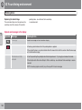
Immobiliser
Each remote control key has a unique code.
The car can only be driven with the correct
remote control key with the correct code.
The following error messages in the combined
instrument panel's information display are related to the electronic immobiliser:
02 Locks and alarm
Remote control key/key blade
Key error Reinsert
key
Error reading the
remote control key
during starting Remove the key, reinsert it and try to
start again.
Car key not found
Error reading the
PCC during starting
- Try to start again.
(Only applies to Keyless drive with PCC.)
If the error persists:
Insert the remote
key into the ignition
switch and try to
start again.
Immobiliser Try
start again
Error in immobiliser
system during starting. If the fault persists the recommendation is to contact
an authorised Volvo
workshop.
For starting the car, see page 115.
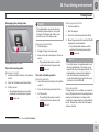
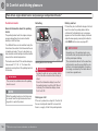
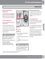
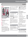
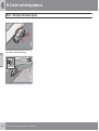
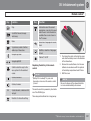
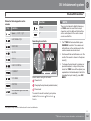
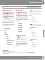
Functions
02
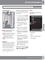
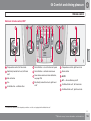
Remote control key, standard version.
Locking
G021079
Specification
G021078
Message
Remote control key with PCC* - Personal Car
Communicator.
Information
Unlocking
Function buttons
Approach light duration
Locking – Locks the doors and tailgate
while the alarm is activated.
Tailgate
Panic function
Press and hold (at least 2 seconds) to close all
the windows and sunroof* simultaneously.
WARNING
If the sunroof and windows are closed using
the remote control key, check that no one is
in danger of getting hands caught.
Unlocking – Unlocks the doors and tailgate while the alarm is deactivated.
``
* Option/accessory, for more information, see Introduction.
49
02 Locks and alarm
Remote control key/key blade
5 seconds. Otherwise the function switches off
automatically after 2 minutes and 45 seconds.
The function can be changed from unlocking
all doors simultaneously, to unlocking the driver's door only with one press of the button and,
after a further press of the button - within 10
seconds - unlocking the remaining doors.
Range
The function can be changed in the menu system MY CAR under Settings Car settings
Lock settings Doors unlock with both
the alternatives All doors and Enter current
PIN. For a description of the menu system, see
page 148.
Approach light duration – Used to switch
on the car's lighting at a distance. For more
information, see page 95.
The remote key's functions have a range of
about 20 m from the car.
If the car does not verify a button being pressed
- move closer and try again.
NOTE
The remote control key functions can be
disrupted by surrounding radio waves,
buildings, topographical conditions etc. The
car can always be locked/unlocked using
the key blade, see page 51.
Tailgate - Unlocks and disarms the alarm
for the tailgate only. On cars with power tailgate* the tailgate is opened after the button is
kept depressed. For more information, see
page 62.
Panic function – Used to attract attention
in an emergency.
Press and hold the button for at least 3 seconds or press it twice within 3 seconds to activate the direction indicators and the horn.
The function can be turned off with the same
button once it has been active for at least
50
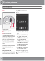
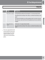
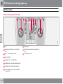
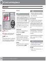
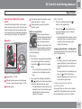
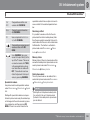
Unique PCC functions*
* Option/accessory, for more information, see Introduction.
G021080
02
Press and hold (at least 4 seconds) to open all
windows simultaneously.
Remote control key with PCC* - Personal Car
Communicator.
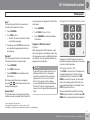
Information button
Indicator lamps
Using the information button enables access to
certain information from the car via the indicator lamps.
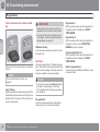
Using the information button
Press the information button
.
> All indicator lamps flash for approximately 7 seconds and the light travels
around on the PCC. This indicates that
information from the car has been read.
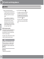
02 Locks and alarm
Remote control key/key blade
If any of the other buttons are pressed
during this time then the reading is interrupted.
NOTE
If none of the indicator lamps illuminates with repeated use of the information
button and in different locations (as well as
after 7 seconds and after the light has travelled around on the PCC), contact a workshop - an authorised Volvo workshop is recommended.
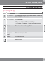
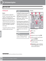
Indicator lamps display information in accordance with the following illustration:
Red continuous light – the alarm has been
triggered since the car was locked.
Red light flashing alternately in both indicator lamps – The alarm was triggered less
than 5 minutes ago.
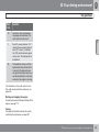
Range PCC
The PCC's range for locking, unlocking and
tailgate is about 20 m from the car - for other
functions up to about 100 m.
If the car does not verify a button being pressed
- move closer and try again.
NOTE
The information button functions can be
disrupted by surrounding radio waves,
buildings, topographical conditions etc.
If no indicator lamps illuminate when
the information button is used within range
then this may be because the last communication between the PCC and the car was
disrupted by surrounding radio waves,
buildings, topographical conditions etc.
02
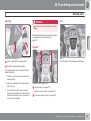
Detachable key blade
A remote control key contains a detachable
key blade of metal with which some functions
can be activated and some operations carried
out.
The key blade's unique code is provided by
authorised Volvo workshops, which are recommended when ordering new key blades.
Out of PCC range
Key blade functions
If the PCC is too far away from the car for the
information to be read then the status the car
was last left in is shown, without the light travelling around on the PCC.
Using the remote control key's detachable key
blade:
If several PCCs are used for the car then it is
only the PCC last used for locking/unlocking
that shows correct status.
Green continuous light – the car is locked.
NOTE
• the driver's door can be opened manually
if central locking cannot be activated with
the remote control key, see page 58.
• the rear doors' mechanical child safety
locks can be activated/deactivated, see
page 65.
Yellow continuous light – the car is
unlocked.
``
51
02 Locks and alarm
Remote control key/key blade
• access to the glovebox and cargo area
02
2. Lightly press the key blade. You should
hear a "click" when the key blade is locked
in.
(privacy locking*) can be blocked, see
page 53.
• the airbag for front passenger seat
(PACOS)* can be activated/deactivated,
see page 24.
Removing the key blade
Unlocking doors with the key blade
If central locking cannot be activated with the
remote control key - e.g. if the batteries are
discharged - then the driver's door can be
opened as follows:
1. Unlock the driver's door with the key blade
in the door handle's lock cylinder.
See also the figure and further information
on page see page 58.
G021082
NOTE
When the door has been unlocked using the
key blade and is opened, the alarm is triggered.
Slide the spring-loaded catch to the side.
At the same time pull the key blade straight
out backwards.
Attaching the key blade
2. Deactivate the alarm by inserting the
remote control key in the ignition switch.
For a car with the Keyless system, see
page 58.
Carefully refit the key blade into its location in
the remote control key.
1. Hold the remote control key with the slot
pointed up and lower the key blade into its
slot.
52
* Option/accessory, for more information, see Introduction.
02 Locks and alarm
Privacy locking*
General information on privacy locking
locked and the tailgate lock is disconnected
from the central locking - the tailgate cannot be
opened with either the central locking button in
the front doors or the remote control key.
Activate/deactivate
02
G017869
This means that the remote control key without
key blade can only be used to activate/deactivate the alarm, to open the doors and to drive
the car.
Active locks for remote control key with key blade.
The remote control key without key blade can
then be handed over to the service or hotel staff
- the loose key blade is retained by the car
owner.
Activating privacy locking.
NOTE
To activate privacy locking:
Do not forget to pull out the cargo cover
over the cargo area before closing the tailgate, see page 300.
Insert the key blade in the glovebox lock
cylinder.
Turn the key blade 180 degrees clockwise.
The keyhole is vertical in the locked position for privacy locking.
G017870
Pull out the key blade. The information display shows a message at the same time.
Active locks for remote control key, without key
blade and privacy locking activated.
The glovebox is then locked and the tailgate
can no longer be unlocked with the remote
control key or the central locking button.
The privacy locking function is intended for
when the car is left for service, with a hotel
parking valet or similar. The glovebox is then
``
* Option/accessory, for more information, see Introduction.
53
02 Locks and alarm
Privacy locking*
NOTE
02
Do not reinsert the key blade into the remote
control key but keep it in a safe place
instead.
• Deactivation takes place in reverse order.
For information on locking the glovebox only,
see page 61.
54
* Option/accessory, for more information, see Introduction.
02 Locks and alarm
Battery replacement, remote control key/PCC*
Replacing the battery
Battery replacement
Closely study how the battery/batteries are
secured on the inside of the cover, with
regard to their (+) and (–) sides.
The batteries should be replaced if:
• the information symbol is illuminated and
the display shows Low battery in remote
control. Please change batteries.
Remove control key (1 battery)
and/or
1. Carefully prize out the battery.
• the locks repeatedly do not react to signals
2. Install a new one with the (+) side down.
from the remote control key within
20 metres from the car.
02
PCC* (2 batteries)
1. Carefully prize out the batteries.
Opening
2. First install one new one with the (+) side
up.
Slide the spring-loaded catch to the
side.
3. Position the white plastic tab in between
and finally install a second new battery with
the (+) side down.
At the same time pull the key blade
straight out backwards.
Insert a 3 mm slot screwdriver in the
hole behind the spring-loaded catch and
gently prize the remote control key up.
NOTE
Battery type
Use batteries with the designation CR2430, 3V
- one in the remote control key and two in the
PCC.
Assembly
Turn the remote control key over with the
buttons facing up, this is to avoid the batteries falling out when it is opened.
1. Press the remote control key together.
2. Hold the remote control key with the slot
pointed up and lower the key blade into its
slot.
IMPORTANT
Avoid touching the battery and its terminals
with your fingers, as this could damage their
functionality.
3. Lightly press the key blade. You should
hear a "click" when the key blade is locked
in.
``
* Option/accessory, for more information, see Introduction.
55
02 Locks and alarm
Battery replacement, remote control key/PCC*
IMPORTANT
02
56
Make sure that you dispose of old batteries
in an environmentally-friendly way.
* Option/accessory, for more information, see Introduction.
02 Locks and alarm
Keyless drive*
Keyless lock and ignition system (only
PCC1)
General
the car door handle or tailgate. This means that
the person who wishes to lock or unlock a door
must have the PCC with him or her. It is not
possible to lock or unlock a door if the PCC is
on the opposite side of the car.
The red rings in the preceding illustration indicate the range covered by the system's antennas.
If all PCCs are removed from the car when the
engine is running or key position II is active
(see page 82) and if all doors are closed, then
a warning message is shown in the information
display and an audio reminder signal sounds at
the same time.
The keyless drive function in the PCC allows
the car to be unlocked, driven and locked without the need for a key. You simply have to have
the PCC with you. The system makes it easier
and more convenient to open the car, e.g.
when your hands are full.
Both of the car's PCCs incorporate the Keyless
function. Additional PCCs can be ordered, see
page 48.
PCC range
In order to open a door or the tailgate, a PCC
must be no more than approx. 1.5 metres from
1
reactivated. It is therefore important to handle
all PCCs with great care.
02
IMPORTANT
Never leave a PCC behind in the car.
Interference to PCC function
Electromagnetic fields and screening can interfere with the keyless drive system. For this reason, do not place the PCC near mobile phones
or metallic objects.
If interference is experienced nonetheless, use
the PCC and the key blade as a remote control
key, see page 49.
The warning message clears and the audio
reminder signal stops when the PCC is brought
back to the car after:
• a door has been opened and closed
• the PCC is inserted into the ignition switch
• the READ button has been pressed.
Handling the PCC safely
If a PCC with keyless drive function is left in the
car, it is deactivated temporarily when the car
is locked. This prevents unauthorised entry.
However, if someone breaks into the car,
opens the door and finds the PCC, it can be
Personal Car Communicator, see page 50.
``
* Option/accessory, for more information, see Introduction.
57
02 Locks and alarm
Keyless drive*
Locking
Unlocking
Unlocking takes place when a hand grasps a
door handle or the tailgate's rubberised pressure plate is actuated - open the door or tailgate as normal.
02
Unlocking with the key blade
1. Press the key blade approx. 1 cm straight
up into the hole on the underside of the
door handle/cover - do not prize.
> The plastic cover loosens automatically
by means of the torque when the blade
is pushed straight up and into the opening.
2. Then insert the key blade in the lock cylinder and unlock the door.
3. Refit the plastic cover after unlocking.
NOTE
Cars with the keyless system have a button on the
outside door handles.
When the driver's door is unlocked using the
key blade and is opened, the alarm is triggered. It is switched off by inserting the PCC
in the ignition switch, see page 67.
Lock the doors and the tailgate by pressing the
lock button on one of the door handles on the
outside.
All doors and the tailgate must be closed
before the car can be locked - otherwise the
car is not locked.
NOTE
On cars with automatic transmission, the
gear selector must be set in the P position
– otherwise the car cannot be locked or the
alarm armed.
2
58
Hole for key blade - to loosen the cover.
If central locking cannot be activated with the
PCC, e.g. if the batteries are discharged, then
the driver's door can be opened with the PCC's
detachable key blade (see page 51).
To access the lock cylinder, the door handle's
plastic cover must be removed - this is also
done with the key blade:
Only in combination with power driver's seat and power mirrors.
* Option/accessory, for more information, see Introduction.
Key memory2 – driver's seat and door
mirrors
PCC memory function
If several people each with a PCC approach the
car, then the settings for seat and mirrors are
implemented for the person who opens the
driver's door.
After the driver's door has been opened by
person A with PCC-A, but person B with PCC-
02 Locks and alarm
Keyless drive*
B shall drive, the settings can be changed in
three ways:
Antenna location
WARNING
People with pacemaker operations should
not come closer than 22 cm to the keyless
system's antennae with their pacemaker.
This is to prevent interference between the
pacemaker and the keyless system.
• Standing by the driver's door, or sitting
behind the steering wheel, person B
presses their PCC's unlock button, see
page 49.
02
• Select one of three possible memories for
seat adjustment with seat button 1-3, see
page 85.
• Adjust seat and mirrors manually, see
G021179
page 85 and 105.
Lock settings
The Keyless function can be adapted by indicating in the menu system MY CAR which
doors shall be unlocked, under Car settings
Lock settings Keyless entry - there
select between All doors unlock, Any door,
Doors on same side and Both front doors.
For a description of the menu system, see
page 148.
The keyless system has a number of integrated
antennae located around the car:
Tailgate, by wiper motor
Door handle, left rear
Roof, centre above rear seat
Cargo area, central and furthest in under
the floor
Door handle, right rear
Centre console, under the rear section
Centre console, under the front section.
* Option/accessory, for more information, see Introduction.
59
02 Locks and alarm
Locking/unlocking
From the outside
02
The remote control key can lock/unlock all
doors and the tailgate simultaneously. Different
sequences for unlocking can be selected, see
"Unlocking with the remote control key" page
49.
In order that the lock sequence can be activated, the driver's door must be closed - if any
of the other doors or the tailgate is open, then
it/they is/are locked and the alarm is activated
only when it/they are closed. With the Keyless* system all the doors and tailgate must be
closed.
NOTE
WARNING
Be aware of the risk of being locked in the
car when it is locked from the outside using
the remote control key - it is then not possible to open any of the doors from the
inside with the door controls. Read more
about this in the section "Deadlocks" later
on.
Central locking
Automatic relocking
If none of the doors or the tailgate is opened
within 2 minutes of unlocking, all are locked
again automatically. This function reduces the
risk that the car is left unlocked unintentionally.
(For cars with alarm, see page 66.)
Be aware of the risk of locking the remote
control key in the car.
If it is not possible to lock/unlock with the
remote control key, the battery may be discharged - lock or unlock the driver's door with
the detachable key blade, see page 51.
NOTE
Remember that the alarm is triggered when
the door is opened after being unlocked
with the key blade - the alarm is switched
off when the remote control key is inserted
into the ignition switch.
60
From the inside
* Option/accessory, for more information, see Introduction.
Central locking.
All of the doors and the tailgate can be locked
or unlocked simultaneously using the central
locking button on either front door.
• Press one side
the other side
of the button to lock to unlock.
Unlocking
A door can be unlocked from the inside in two
different ways:
• Press the central locking button
.
Press and hold (at least 4 seconds) to also
open all the side windows* simultaneously.
02 Locks and alarm
Locking/unlocking
• Pull the door handle once and release - the
Glovebox
Tailgate
door is unlocked. Pull the door handle
again to open the door.
Unlocking with the remote control key
02
Locking
• Press the central locking button
after
the front doors have been closed.
Press and hold (at least 2 seconds) to also
close all the side windows and the sunroof*
simultaneously.
All doors can also be individually locked manually with their lock buttons - the door in question must then be closed.
Global opening
Press and hold the central locking button
(at least 4 seconds) to also open all the windows simultaneously - for example, to quickly
ventilate the passenger compartment during
hot weather.
Automatic locking
The doors and tailgate are locked automatically when the car starts to move.
The function can be activated/deactivated in
the menu system MY CAR under Settings
Car settings Lock settings Doors
automatic lock. For a description of the menu
system, see page 148.
The glovebox can only be locked/unlocked
using the remote control key's detachable key
blade. For information on the key blade, see
page 51.
The alarm for the tailgate can be disarmed* and
the tailgate unlocked on its own by using the
remote control key's
button.
Locking the glovebox:
Turn the key blade 90 degrees clockwise.
The keyhole is horizontal in the locked
position.
If the car is equipped with an alarm* the alarm
indicator on the instrument panel stops to
show that alarm for the whole of the car is not
armed. The alarm's level and movement sensors and the sensors for opening the tailgate
are disconnected.
Pull out the key blade.
The doors remain locked and armed.
Insert the key blade in the glovebox lock
cylinder.
• Unlock by carrying this out in reverse
order.
For information on privacy locking, see
page 53.
• The tailgate is unlocked, but remains
closed - press lightly on the rubberised
pressure plate under the outer handle and
lift the tailgate.
``
* Option/accessory, for more information, see Introduction.
61
02 Locks and alarm
Locking/unlocking
If the tailgate is not opened within 2 minutes
then it is relocked and the alarm is re-armed.
Power operated tailgate*
NOTE
02
•
If the system has been operating continuously for a long time, it is switched
off to avoid overload. It can be used
again after about 2 minutes.
•
If the battery has been discharged or
disconnected then the tailgate must be
opened and closed again to reset the
system.
G017876
Unlocking the car from inside
NOTE
To unlock the tailgate:
Press the lighting panel button (1).
> The tailgate is unlocked and can be
opened within 2 minutes (if the car is
locked from the inside).
Consider the roof height when using electrical operation. Do not use electrical operation of the tailgate under a low roof height,
see under the heading "Interrupt opening/
closing of tailgate".
Locking with the remote control key
Press the remote control key's button for
, see page 49.
locking,
> If the car is equipped with an alarm* the
alarm indicator on the instrument panel
starts to flash, which means that the
alarm is armed.
62
* Option/accessory, for more information, see Introduction.
Programmable max. opening
Tailgate maximum opening position can be
programmed. Can be used for e.g. low roof
height in a garage. Proceed as follows:
• Open the tailgate manually, hold it in the
desired position and give the button on the
tailgate one long press (at least 3 seconds)
and then release the tailgate - the programming is complete.
• To clear the programming - move the tailgate manually to a higher position.
Snow and wind
If the tailgate is forced down by something just
when it is being opened, e.g. snow, ice or
strong wind, and this causes the tailgate to
lower, then it is closed automatically.
02 Locks and alarm
Locking/unlocking
Pinch protection
If something with sufficient resistance prevents
the tailgate from opening/closing then the
pinch protection is activated.
• Long press on the button in the lighting
panel - hold the button depressed until the
tailgate starts to open.
• Long press on the button on the remote
control key - hold the button depressed
until the tailgate starts to open.
• During opening - power tailgate operation
is deactivated and the tailgate is disengaged.
WARNING
Pay attention to the risk of crushing when
opening/closing. Before starting to open/
close; make sure that there is nobody close
to the tailgate as a crushing injury could
have serious consequences.
Always operate the tailgate with caution.
Opening the tailgate
The tailgate can be opened three
ways (two of which involve this button):
sure plate under the outer handle.
02
• The tailgate can then be operated manually.
Deadlocks*1
Closing the tailgate
Close using this button on the tailgate
or manually.
• Press the button – the tailgate closes automatically.
Stop the opening/closing of the tailgate
This can be done four ways (of which
three involve this button):
•
•
•
•
Press the lighting panel button
Deadlocks means that all lock buttons and
door handles are mechanically disengaged,
which prevents doors being opened from the
inside.
The deadlocks are activated with the remote
control key and are set after an approximately
10 second delay after the doors have been
locked.
NOTE
Press the remote control key button
If a door is opened within the delay time then
the sequence is interrupted and the alarm is
deactivated.
Press the tailgate's button
Press the rubberised pressure plate
beneath the outside handle.
- The tailgate's movement is interrupted and it
stops.
1
The system is disengaged if the opening/closing sequence is interrupted in accordance with
the preceding section.
• Push down gently on the rubberised pres-
• When closing - the tailgate stops and
backs off from the obstacle a couple of
centimetres.
Manual tailgate operation
The car can only be unlocked from a deadlock
state with the remote control key. The driver's
door can also be unlocked with the detachable
key blade.
Only in combination with alarm.
``
* Option/accessory, for more information, see Introduction.
63
02 Locks and alarm
Locking/unlocking
WARNING
02
Do not allow anyone to remain in the car
without first deactivating the deadlocks in
order to avoid the risk of anyone being
locked in.
Temporary deactivation
1. Access the menu system MY CAR under
Settings Car settings Reduced
guard (for a detailed description of the
menu system, see page 148).
2. Select Activate once.
> The instrument panel display shows the
message Reduced guard See
manual and the deadlocks function is
switched off when the car is locked.
or
Active menu options are indicated with a cross.
MY CAR
OK MENU
If the deadlocks function shall be switched
off
TUNE knob control
EXIT
If someone is going to stay in the car but the
doors must be locked from the outside, then
the deadlocks function can be temporarily
switched off. This is carried out as follows:
64
Select Ask on exit.
> Each time the engine is switched off the
centre console display screen shows
the message Activate Reduced Guard
until engine has started again? followed by the alternatives Confirm with
OK and Cancel with EXIT.
* Option/accessory, for more information, see Introduction.
Press OK/MENU and lock the car. (Note
that the alarm's movement and tilt detectors* are switched off at the same time, see
page 67.)
> The next time the engine is started, the
system is reset to zero and the instrument panel display shows the message
Full guard at which the deadlocks
function and the alarm's movement and
tilt detectors are re-engaged.
If the locking system shall not be changed
Press EXIT and lock the car.
NOTE
•
Remember that the alarm is activated
when the car is locked.
•
If any of the doors are opened from the
inside then the alarm is triggered.
02 Locks and alarm
Child safety locks
Manual blocking of the rear doors
NOTE
The child safety locks prevent children from
opening a rear door from the inside.
•
A door's knob control only blocks that
particular door - not both rear doors
simultaneously.
•
Cars with an electric child safety lock do
not have a manual child lock.
Electrical locking of the rear doors*
and power windows
1. Start the engine or choose a key position
higher than 0.
2. Press the button in the driver's door control
panel.
> The information display shows the message Rear child locks Activated and
the button's lamp illuminates - the locks
are active.
02
When the electric child safety lock is active
then the rear:
• windows can only be opened with the drivG021077
er's door control panel
• doors cannot be opened from inside.
The current setting is stored when the engine
is switched off - if the child safety locks are
activated at engine shutdown, the function will
remain activated the next time the engine is
started.
The child safety locks are located on the trailing
edge of the rear doors and are only accessible
when the doors are open.
To activate/deactivate the child safety locks:
Use the remote control key's detachable
key blade to turn the knob - see page 51.
The door is blocked against opening from
the inside.
The door can be opened from both the
outside and the inside.
Control panel driver's door.
The child safety locks can be activated/deactivated in all key positions higher than 0 - see
page 82. Activation/deactivation can be performed up to 2 minutes after switching off the
engine, provided that no door is opened.
To activate the child safety locks:
* Option/accessory, for more information, see Introduction.
65
02 Locks and alarm
Alarm*
General
02
Activated alarm is triggered if:
• a door, the bonnet or the tailgate is opened
• a movement is detected in the passenger
compartment (if fitted with a movement
detector*)
• the car is raised or towed away (if fitted
with a tilt detector*)
• the battery's cable is disconnected
• the siren is disconnected.
If there is a fault in the alarm system, the information display shows a message. In which
case, contact a workshop - an authorised
Volvo workshop is recommended.
NOTE
Alarm indicator
The movement sensors trigger an alarm in
the event of movement in the passenger
compartment - air currents are also registered. For this reason the alarm is triggered
if the car is left with a window or the sunroof
open or if the passenger compartment
heater is used.
To avoid this: Close the window/sunroof
when leaving the car. If the car's integrated
passenger compartment heater (or a portable electric heater) shall be used - direct the
airflow from the air vents so that they are not
pointing upwards in the passenger compartment.
NOTE
Do not attempt to repair or modify alarm
system components. All such attempts
could affect the terms of insurance.
A red LED on the instrument panel indicates
the alarm system's status:
• LED not lit – Alarm not armed
• The LED flashes once every other second
– Alarm is armed
• The LED flashes rapidly after disarming the
alarm (and until the remote control key is
inserted in the ignition switch and key position I is selected) – Alarm has been triggered.
Arming the alarm
Press the remote control key lock button.
Deactivate the alarm
66
* Option/accessory, for more information, see Introduction.
Press the remote control key unlock button.
02 Locks and alarm
Alarm*
Deactivating a triggered alarm
Reduced alarm level
To avoid accidental triggering of the alarm e.g. if a dog is left in a locked car or during
transport on a car train or car ferry - the movement and tilt detectors should be temporarily
deactivated.
Press the remote control key unlock button
or insert the remote control key in the ignition switch.
Other alarm functions
The procedure is the same as with the temporary disengaging of deadlocks, see page 63.
Automatic re-arming of the alarm
This function prevents the car being left with
the alarm disarmed unintentionally.
If the car is unlocked with the remote control
key (and the alarm is disarmed) but none of the
doors or the tailgate is opened within 2
minutes, then the alarm is automatically rearmed. The car is relocked at the same time.
Remote control key not working
If the alarm cannot be deactivated with the
remote control key, e.g. if the key's battery is
discharged - the car can be unlocked, disarmed and the engine started as follows:
1. Open the driver's door with the detachable
key blade - see page 58.
> The alarm is triggered, the alarm indicator flashes rapidly and the siren sounds.
02
Testing the alarm system
2. Insert the remote control key in the ignition
switch.
> The alarm is deactivated and the alarm
indicator goes out.
3. Start the engine.
1. Close all windows. Remain in the car.
2. Engage the alarm function with the remote
control key's lock button.
3. Wait 15 seconds.
Alarm signals
When the alarm is triggered, the following happens:
• A siren sounds for 30 seconds or until the
alarm is switched off. The siren has its own
battery and works independently of the car
battery.
• The direction indicators flash for 5 minutes
or until the alarm is switched off.
Testing the movement detector in the
passenger compartment
4. Trigger the alarm by moving your arms forward and back at backrest height.
> A siren should sound and all direction
indicators should flash.
5. Deactivate the alarm by unlocking the car
with the remote control key.
Test of alarm for doors
1. Engage the alarm function with the remote
control key's lock button.
2. Wait 15 seconds.
``
* Option/accessory, for more information, see Introduction.
67
02 Locks and alarm
Alarm*
3. Unlock the driver's door with the detachable key blade.
02
4. Open the driver's door.
> A siren should sound and all direction
indicators should flash.
5. Deactivate the alarm by unlocking the car
with the remote control key.
Testing the alarm sensors for the bonnet
1. Sit in the car and deactivate the movement
detector, see the previous section
"Reduced alarm level".
2. Remain sitting in the car and engage the
alarm function with the remote control
key's lock button.
3. Wait 15 seconds.
4. Open the bonnet with the handle under the
dashboard.
> A siren should sound and all direction
indicators should flash.
5. Deactivate the alarm by unlocking the car
with the remote control key.
68
* Option/accessory, for more information, see Introduction.
02 Locks and alarm
02
69
Instruments and controls........................................................................ 72
Volvo Sensus ......................................................................................... 81
Key positions.......................................................................................... 82
Seats....................................................................................................... 84
Steering wheel........................................................................................ 89
Lighting................................................................................................... 90
Wipers and washing.............................................................................. 100
Windows, rearview and door mirrors.................................................... 103
Compass*.............................................................................................. 108
Power sunroof*..................................................................................... 109
Alcoguard*............................................................................................ 111
Starting the engine................................................................................ 115
Starting the engine – Flexifuel............................................................... 117
Starting the engine – external battery................................................... 119
Gearboxes............................................................................................. 120
Eco DRIVe*............................................................................................ 126
All-wheel drive – AWD*......................................................................... 131
Foot brake............................................................................................. 132
HDC Hill Descent Control..................................................................... 134
Parking brake........................................................................................ 136
HomeLink *.......................................................................................... 140
70
* Option/accessory, for more information, see Introduction.
YOUR DRIVING ENVIRONMENT
03 Your driving environment
Instruments and controls
Instrument overview
03
Left-hand drive.
72
03 Your driving environment
Instruments and controls
Function
Page
Function
Page
Menus and messages,
direction indicators,
main/dipped beam, trip
computer
90,
93, 146,
170
Control panel for climate
control
156
Gear selector
120
Cruise control
175, 179
Controls for active chassis (Four-C)*
174
Horn, airbags
22, 89
Wipers and washing
100, 101
Combined instrument
panel
75, 79
Steering wheel adjustment
89
Menu, audio and phone
control
148,
230, 258,
279
Parking brake
136
Bonnet opener
328
START/STOP ENGINE
key
115
Seat adjustment*
84
Ignition switch
82
61, 90,
289
Hazard warning flashers
93
Headlamp control,
opener for fuel filler flap
and tailgate
Door handle
–
Control panel
60, 65,
103, 105
Menu control and audio
system
148,
230, 279
03
``
* Option/accessory, for more information, see Introduction.
73
03 Your driving environment
Instruments and controls
03
Right-hand drive.
74
03 Your driving environment
Instruments and controls
Information displays
Function
Page
Function
Page
Hazard warning flashers
93
Parking brake
136
START/STOP ENGINE
key
115
Steering wheel adjustment
89
Ignition switch
82
Cruise control
175, 179
Menus and messages,
direction indicators,
main/dipped beam, trip
computer
90,
93, 146,
170
Combined instrument
panel
75, 79
Controls for active chassis (Four-C)*
174
Horn, airbags
22, 89
Gear selector
120
Menu, audio and phone
control
148,
230, 258,
279
Control panel for climate
control
156
Wipers and washing
100, 101
Menu control and audio
system
148,
230, 279
Headlamp control,
opener for fuel filler flap
and tailgate
61, 90,
289
Door handle
–
Control panel
60, 65,
103, 105
Seat adjustment*
84
Bonnet opener
328
03
The information displays show information on
some of the car's functions, e.g. cruise control,
trip computer and messages. The information
is shown with text and symbols.
There are further descriptions under the functions that use the information displays.
``
* Option/accessory, for more information, see Introduction.
75
03 Your driving environment
Instruments and controls
Meters
Indicator, information and warning
symbols
If the engine does not start or if the functionality
check is carried out in key position II then all
symbols go out after 5 seconds except the
symbol for faults in the car's emissions system
and the symbol for low oil pressure.
Indicator and information symbols
03
Symbol
Specification
ABL fault
Emissions system
Meters in the combined instrument panel.
Speedometer
ABS fault
Indicator and warning symbols.
Main beam and direction indicator symbol
Fuel gauge. See also Trip computer, page
170, and Refuelling, page 289.
Indicator and warning
Tachometer. The meter indicates engine
speed in thousands of revolutions per
minute (rpm).
Symbol for DRIVe - Start/Stop*, see
page 126
Indicator and information symbols
Functionality check
All indicator and warning symbols illuminate in
key position II or when the engine is started.
When the engine has started, all the symbols
should go out except the parking brake symbol, which only goes out when the brake is disengaged.
1
76
Rear fog lamp on
symbols1
Stability system
Stability system, sport mode
Engine preheater (diesel)
Low level in fuel tank
Information, read display text
For certain engine variants, the symbol for low oil pressure is not used. Warnings are made via display text. For information on checking the oil level, see page 329.
* Option/accessory, for more information, see Introduction.
03 Your driving environment
Instruments and controls
Symbol
Specification
Main beam On
checked. Volvo recommends that you
seek assistance from an authorised Volvo
workshop.
Rear fog lamp on
Left-hand direction indicators
Right-hand direction indicators
This symbol illuminates when the rear fog lamp
is on. There is only one fog lamp. It is located
on the driver's side.
Stability system
DRIVe - Start/Stop*
ABL fault
The symbol illuminates if a fault has arisen in
the ABL function (Active Bending Lights).
A flashing symbol indicates that the stability
system is operating. If the symbol illuminates
with constant glow then there is a fault in the
system.
Stability system, Sport mode
If the symbol illuminates then it may be due to
a fault in the car's emissions system. Drive to
a workshop for checking. Volvo recommends
that you seek assistance from an authorised
Volvo workshop.
Sport mode allows for a more active driving
experience. The system then detects whether
the accelerator pedal, steering wheel movements and cornering are more active than in
normal driving and then allows controlled skidding of the rear section up to a certain level
before it intervenes and stabilises the car.
ABS fault
Engine preheater (diesel)
Emissions system
If this symbol illuminates then the system is not
working. The car's regular brake system continues to work, but without the ABS function.
1. Stop the car in a safe place and turn off the
engine.
2. Restart the engine.
Information, read display text
When one of the car's systems does not
behave as intended, this information symbol
illuminates and a text appears on the information display. The message text is cleared with
the READ button, see page 146, or it disappears automatically after a time (time depending on which function is indicated). The information symbol can also illuminate in conjunction with other symbols.
03
NOTE
When a service message is shown, the symbol and message are cleared using the
READ button, or clear automatically after a
while.
Main beam On
The symbol illuminates when main beam is on
and with main beam flash.
Left/right-hand direction indicators
This symbol illuminates during engine preheating. Preheating occurs when the temperature
is below 2 °C. The car can be started once the
symbol goes out.
Both direction indicator symbols flash when
the hazard warning flashers are used.
Low level in fuel tank
When the symbol illuminates the level in the
fuel tank is low, refuel as soon as possible.
3. If the symbol remains illuminated, drive to
a workshop to have the ABS system
``
* Option/accessory, for more information, see Introduction.
77
03 Your driving environment
Instruments and controls
Indicator and warning symbols
Symbol
Specification
Low oil pressureA
03
Parking brake applied
This symbol illuminates with a constant glow
when the parking brake is applied. The symbol
flashes during application, and then changes
over to a constant glow.
A flashing symbol means that a fault has arisen.
Read the message on the information display.
1. Stop the car in a safe place and turn off the
engine.
Airbags – SRS
Airbags – SRS
2. Restart the engine.
Alternator not charging
Fault in brake system
If this symbol remains illuminated or illuminates
while driving, it means a fault has been
detected in the seatbelt buckle, SRS, SIPS, or
IC systems. Drive immediately to a workshop
to have the system checked. Volvo recommends that you seek assistance from an
authorised Volvo workshop.
Seatbelt reminder
Warning
For certain engine variants, the symbol for low oil pressure
is not used. Warnings are made via display text, see pages
329 and 331.
Low oil pressure
If this symbol illuminates during driving then
the engine's oil pressure is too low. Stop the
engine immediately and check the engine oil
level, top up if necessary. If the symbol illuminates and the oil level is normal, contact a
workshop. Volvo recommends that you seek
assistance from an authorised Volvo workshop.
78
If the brake and ABS symbols illuminate at the
same time, there may be a fault in the brake
force distribution system.
Parking brake applied
Seatbelt reminder
A
and check the level in the brake fluid reservoir,
see page 333.
This symbol illuminates if someone in a front
seat has not put on their seatbelt or if someone
in a rear seat has taken off their seatbelt.
• If both symbols extinguish, continue
driving.
• If the symbols remain illuminated, check
the level in the brake fluid reservoir, see
page 333. If the brake fluid level is normal but the symbols are still illuminated,
the car can be driven, with great care, to
a workshop to have the brake system
checked. Volvo recommends that you
seek assistance from an authorised
Volvo workshop.
Alternator not charging
This symbol illuminates during driving if a fault
has occurred in the electrical system. Visit a
workshop. Volvo recommends that you seek
assistance from an authorised Volvo workshop.
Fault in brake system
If this symbol illuminates, the brake fluid level
may be too low. Stop the car in a safe place
WARNING
If the brake fluid is under the MIN level in the
brake fluid reservoir, do not drive further
before topping up the brake fluid.
The loss of brake fluid must be investigated
by a workshop. Volvo recommends that you
contact an authorised Volvo workshop.
03 Your driving environment
Instruments and controls
WARNING
If the brake and ABS symbols are illuminated at the same time, there is a risk that
the rear end will skid during heavy braking.
Warning
The red warning symbol illuminates when a
fault has been indicated which could affect the
safety and/or driveability of the car. An explanatory text is shown on the information display
at the same time. The symbol remains visible
until the fault has been rectified but the text
message can be cleared with the READ button, see page 146. The warning symbol can
also illuminate in conjunction with other symbols.
atory text message in the combined instrument
panel. Stop the car in a safe place as soon as
possible and close the door, bonnet or boot lid,
whichever is open.
If the car is driven at a speed lower than
approx. 7 km/h then the information
symbol illuminates.
If the car is driven at a speed higher
than approx. 7 km/h then the warning
symbol illuminates.
Display for trip meter
Controls for switching between trip meters
T1 and T2, as well as resetting the trip
meters.
The meters are used to measure short distances.
03
One short press on the control switches
between the two trip meters T1 and T2. A long
press (more than 2 seconds) resets an active
trip meter to zero. The distance is shown in the
display.
Trip meter
Action:
1. Stop in a safe place. Do not drive the car
further.
2. Read the information on the information
display. Implement the action in accordance with the message in the display. Clear
the message using the READ button.
Reminder – doors not closed
Trip meter and controls.
If one of the doors, the bonnet2 or tailgate is not
closed properly then the information or warning symbol illuminates together with an explan-
2
Only cars with alarm*.
``
* Option/accessory, for more information, see Introduction.
79
03 Your driving environment
Instruments and controls
Clock
group MY CAR, for more information see
page 148.
03
Clock and setting knob.
Display for showing the time.
Controls for setting the clock.
Turn the knob clockwise/anticlockwise to set
the clock. Turn first to the end position and then
turn past/over the end position a further
approx. 1 mm - a "click" sounds and is felt in
the button. Each "click" scrolls 1 minute. In
order to change quickly - hold in the "click
position".
In connection with a message the clock can be
temporarily replaced by a symbol, see
page 146.
Setting the clock in MY CAR
In addition to the previous manual/mechanical
method the clock can also be set in the menu
80
1. Locate Settings
Time.
System options
2. The cursor is located in the first box for
Hour: Press OK - the box is activated.
3. Turn TUNE to set the correct hour and
press OK - the box is deactivated.
4. Turn TUNE to select the box for Minute (A)
and press OK - the box is activated (B).
5. Turn TUNE to set the correct minute and
press OK - the box is deactivated.
6. Turn TUNE to select the box for OK and
press OK - the setting is complete.
The menu option Settings System options
Time format selects the 24h or 12h system
(AM/PM).
03 Your driving environment
Volvo Sensus
General
the car can be personalised by means of an
intuitive user interface. Settings can be made
in Car settings, Infotainment, Climate, etc.
With the centre console buttons and controls
or the steering wheel's right-hand keypad*
functions can be activated or deactivated and
many different settings can be made.
03
With a press on MY CAR all settings related to
the driving and control of the car are presented,
such as City Safety, Locks and alarm, setting
the clock, etc.
Control panel in centre console
Navigation* - NAV, see separate owner's
manual (Road and Traffic Information System - RTI).
Infotainment (RADIO, MEDIA, TEL*), see
page 228.
Car settings - MY CAR, see page 148.
With a press on the respective function:
RADIO, MEDIA, TEL*, NAV* and CAM* other
sources, systems and functions can be activated, e.g. AM, FM1, CD, DVD*, TV*, Bluetooth*, navigation* and park assist camera*.
For more information on all functions/systems,
see the respective section in the owner's manual.
Park assist camera - CAM*, see
page 212.
Climate control, see page 156.
Volvo Sensus is the car's operating system, the
heart of your personal Volvo experience. Volvo
Sensus combines and presents many functions in several of the car's systems on the
centre console TV screen. With Volvo Sensus
* Option/accessory, for more information, see Introduction.
81
03 Your driving environment
Key positions
Insert and remove the remote control
key
03
IMPORTANT
Foreign objects in the ignition switch may
jeopardise the function or destroy the lock.
With the remote control key fully inserted into
the ignition switch - Briefly press START/
STOP ENGINE.
Do not press the remote control key incorrectly turned - Hold the end with the detachable key blade, see page 51.
Key position II
Withdraw the key
Push the remote control key, allow it to eject,
then pull it out.
Functions
Ignition switch with remote control key extracted/
inserted.
NOTE
For cars with keyless function*, see
page 57.
Insert the key
Hold the end of the remote control key with the
detachable key blade and insert the key in the
ignition switch. Then press the key in the lock
up to its end position.
82
Key position I
The remote control key's 3 different key positions - 0, I and II - can be reached without the
need to start the engine. The table shows the
functions available in each key position.
NOTE
To reach key position I or II without starting
the engine - do not depress the brake/
clutch pedal when the following operations
are carried out.
Key position 0
Insert the remote control key in the ignition
switch and push it in to the end position.
* Option/accessory, for more information, see Introduction.
With the remote control key fully inserted into
the ignition switch - Press START/STOP
ENGINE for about 2 seconds.
From key position II to I
With the remote control key fully inserted into
the ignition switch - Briefly press START/
STOP ENGINE.
Back to key position 0
To resume key position 0 from position I - Open
the driver's door.
03 Your driving environment
Key positions
Position
Function
0
Odometer, clock and temperature gauge are illuminated. The
audio system can be used.
I
Sunroof*, power windows, 12 V
socket in the passenger compartment, RTI*, phone*, ventilation
fan, ECC and windscreen wipers
can be used. The steering lock is
deactivated.
II
The headlamps come on. Warning/indicator lamps illuminate for
5 seconds. All equipment operates apart from heated seats and
rear window defroster, which only
work when the engine is running.
03
For information on the audio system's functions with remote control key removed, see
page 226.
Starting and stopping the engine
For information about starting/switching off the
engine, see page 115.
Towing
For important information about the remote
control key during towing, see page 307.
* Option/accessory, for more information, see Introduction.
83
03 Your driving environment
Seats
Front seats
WARNING
Adjust the position of the driver's seat
before setting off, never while driving. Make
sure that the seat is in locked position in
order to avoid personal injury in the event of
sudden braking or an accident.
Lift the catches on the rear of the backrest
and fold it forward.
4. Push the seat forward so that the head
restraint "locks" in under the glovebox.
Raising takes place in reverse order.
03
Lowering the front seat backrest
WARNING
Grasp the backrest and make sure that it is
properly locked after being folded up in
order to avoid personal injury in the event of
sudden braking or an accident.
Lumbar support adjustment, turn the
wheel1.
Forward/backward: lift the handle to adjust
the distance to the steering wheel and pedals. Check that the seat is locked after
changing position.
Raise/lower* front edge of seat cushion,
pump up/down.
Adjust backrest rake, turn the wheel.
1
84
The passenger seat backrest can be folded
forward to make room for long loads.
Raise/lower the seat, pump up/down.
Move the seat as far back/down as possible.
Control panel for power seat*.
Adjust the backrest to an upright position.
Also applies to power seat.
* Option/accessory, for more information, see Introduction.
03 Your driving environment
Seats
Power seat*
trol key without the key in the ignition switch.
Seat adjustment is normally made in key position I and can always be made when the engine
is running.
Seat with memory function*
2. Hold the button depressed to store settings while depressing one of the memory
buttons.
Using a stored setting
Hold one of the memory buttons depressed
until the seat and the door mirrors stop. If you
release the button then the movement of the
seat will stop.
03
Key memory* in remote control key2
The positions of the driver's seat and the door
mirrors3 are stored in the key memory when the
car is locked with the remote control key.
Front edge of seat cushion up/down
Seat forward/backward and up/down
Backrest rake
The power front seats have overload protection
which is tripped if a seat is blocked by an
object. If this happens, go to key position I or
0 and wait a short time before adjusting the
seat again.
Only one movement (forward/back/up/down)
can be made at a time.
Preparations
Store setting
Memory button
Memory button
Memory button
Button for storing settings
1. Adjust the seat and the door mirrors.
The seats can be adjusted for a certain time
after unlocking the door with the remote con2
3
When the car is unlocked with the same remote
control key it was locked with and the driver's
For key memory for keyless drive, see page 58.
Only if the car is equipped with power seat and retractable power door mirrors.
``
* Option/accessory, for more information, see Introduction.
85
03 Your driving environment
Seats
door is opened, the driver's seat and also the
door mirrors automatically adopt the positions
stored in the key memory.
unlock button on the remote control key. The
driver's door must then be open.
WARNING
NOTE
03
The seat and the door mirrors do not move
if they are already set the relevant position.
It is also possible to use the key memory by
pressing the unlock button on the remote control key when the driver's door is open.
The key memory can be activated/deactivated
in the menu system MY CAR under Settings
Car settings Car key memory
Position of door mirrors and driver's seat in
key. For a description of the menu system, see
page 148.
Risk of crushing! Make sure that children do
not play with the controls. Check that there
are no objects in front of, behind or under
the seat during adjustment. Ensure that
none of the backseat passengers will be
trapped.
Heated/ventilated seats*
Adjust the head restraint according to passenger height so that the whole of the back of the
head is covered if possible. Slide it up as
required.
To lower the head restraint again, the button
(located in the centre between the backrest
and head restraint, see illustration) must be
pressed in while the head restraint is pressed
down.
Manual lowering of the outer head
restraints, rear seat
For heated/ventilated seats, see page 161.
Rear seats
Head restraint, centre seat, rear
NOTE
The key memory in the two remote control
keys and the seat's three memories are
completely independent of each other.
Emergency stop
If the seat accidentally begins to move, press
one of the buttons to stop the seat.
Restarting to reach the seat position stored in
the key memory is performed by pressing the
86
* Option/accessory, for more information, see Introduction.
Pull the locking handle closest to the head
restraint to fold the head restraint forward.
The head restraint is moved back manually
until a "click" can be heard.
03 Your driving environment
Seats
Raising takes place in reverse order.
Lowering the rear seat backrest
NOTE
IMPORTANT
When the backrest has been raised, the red
indicator should no longer be showing. If it
is still showing then the backrest is not
locked in place.
There must be no objects on the rear seat
when the backrest is to be folded down. The
seat belts must not be connected either.
Otherwise there is a risk of damaging the
rear seat upholstery.
WARNING
The triple-section backrest can be folded in
different ways.
Check that the backrests and head
restraints in the rear seats are firmly locked
after raising.
NOTE
The front seats may need to be pushed forwards, and/or the backrests adjusted
upwards, in order that the rear backrests
can be folded forward fully.
• The left-hand section can be folded separately.
• The centre section can be folded separately.
• The right-hand section can only be folded
together with the centre section.
• If the entire backrest is to be folded then
the different sections should be folded
separately.
03
Electrical lowering of the rear seat's
outer head restraints*
If the centre backrest is being lowered fold and adjust the centre backrest's head
restraint downwards, see page 86.
The outer head restraints are lowered automatically when the outer backrests are
lowered. Pull up the backrest's locking
handle
while folding the backrest forward at the same time. A red indicator on
the lock catch
shows that the backrest
is no longer locked in place.
``
* Option/accessory, for more information, see Introduction.
87
03 Your driving environment
Seats
1. The remote control key must be in position
I or II.
2. Press the button to lower the rear outer
head restraints to improve rearward visibility.
03
WARNING
Do not lower the outer head restraints if
there are any passengers using of the outer
seats.
Move the head restraint back manually until a
click is heard.
WARNING
The head restraints must be in locked position after being raised.
88
03 Your driving environment
Steering wheel
Adjusting
Horn
WARNING
Adjust and secure the steering wheel before
driving.
With speed related power steering* the level of
steering force can be adjusted, see
page 174.
03
G021138
Keypads*
Adjusting the steering wheel.
Horn.
Lever - releasing the steering wheel
Press the centre of the steering wheel to signal.
Possible steering wheel positions
The steering wheel can be adjusted for both
height and depth:
1. Pull the lever towards you to release the
steering wheel.
2. Adjust the steering wheel to the position
that suits you.
3. Push back the lever to fix the steering
wheel in place. If the lever is stiff, press the
steering wheel lightly at the same time as
you push the lever back.
Keypads in the steering wheel.
Cruise control, see page 175
Adaptive cruise control*, see page 179
Audio and phone control, see page 228
* Option/accessory, for more information, see Introduction.
89
03 Your driving environment
Lighting
Light switches
The display lighting is automatically subdued
in darkness - the sensitivity is set with the
thumbwheel.
Main/dipped beam
The intensity of the instrument lighting is
adjusted with the thumbwheel.
Headlamp levelling
G021141
03
Overview, light switches.
Thumbwheel1 for adjusting display and
instrument lighting
Rear fog lamp
Front fog lamps*
Light switches
The load in the car changes the vertical alignment of the headlamp beam, which could dazzle oncoming motorists. Avoid this by adjusting
the height of the beam. Lower the beam if the
car is heavily laden.
1. Allow the engine to run or have the remote
control key in position I.
2. Roll the thumbwheel up/down to raise/
lower beam alignment.
Headlamp control and stalk switch.
Position for main beam flash
Position for main beam
Cars with Xenon headlamps* have automatic
headlamp levelling and therefore do not have
the thumbwheel.
Thumbwheel2 for headlamp levelling
Instrument lighting
Different display and instrument lighting is
switched on depending on key position, see
page 82.
1
2
90
The thumbwheel also adjusts brightness for auxiliary lighting in handles, storage compartment in the door, analogue clock*, cup holder in the tunnel console and front floor lighting.
Not available for cars equipped with Xenon headlamps*.
* Option/accessory, for more information, see Introduction.
03 Your driving environment
Lighting
Position
Specification
Automatic dipped beam. Main
beam and main beam flash
work in this positionA/Deactivated dipped beam.
Position/parking lamps
Dipped beam. Main beam and
main beam flash work in this
position.
A
Applies to certain markets.
Main beam flash
Move the stalk switch gently towards the steering wheel to the position for main beam flash.
Main beam comes on until the stalk switch is
released.
Dipped beam
When the engine is started, dipped beam is
activated automatically3 if the headlamp control is in position
. If necessary, automatic dipped beam for this position can be
deactivated by a workshop. Volvo recommends that you contact an authorised Volvo
workshop.
3
In position
dipped beam is always activated automatically when the engine is running
or when the remote control key is in position
II.
Active Xenon headlamps - ABL*
Main beam
Main beam can be activated when the head3 or
.
lamp control is in position
Activate/deactivate main beam by moving the
stalk switch towards the steering wheel to the
end position and release.
When main beam has been activated the symilluminates in the combined instrubol
ment panel.
03
Headlamp pattern with function deactivated (left)
and activated (right) respectively.
If the car is equipped with active Xenon headlamps (Active Bending Lights - ABL) the light
from the headlamps follows the steering wheel
movement in order to provide maximum lighting in bends and junctions and so provide
increased safety.
The function is activated automatically when
the car is started. In the event of a fault in the
symbol illuminates in the
function the
combined instrument panel at the same time
as the information display shows an explanatory text and a further illuminated symbol.
Applies to certain markets.
``
* Option/accessory, for more information, see Introduction.
91
03 Your driving environment
Lighting
Symbol
03
Display
Specification
Headlamp
failure
Service
required
The system
is disengaged. Visit
a workshop
if the message
remains.
Volvo recommends
that you
contact an
authorised
Volvo workshop.
The function5 can be deactivated/activated in
the menu system MY CAR under My XC70
Active bending lights or under Settings
Car settings Light settings Active
bending lights. For a description of the menu
system, see page 149.
For headlamp pattern adjustment, see
page 95.
Position/parking lamps
Rear position lamps also come on when the
tailgate is opened in order to alert anybody
behind.
Brake lights
The brake light automatically comes on during
braking. For information on the Emergency
brake lights and automatic hazard warning
flashers, see page 132.
Front fog lamps
4
5
92
G021145
The function4 can be deactivated/activated in
the menu system MY CAR under My V70
Active bending lights or under Settings
Car settings Light settings Active
bending lights. For a description of the menu
system, see page 149.
G021144
The function is only active in twilight or darkness and only when the car is moving.
Headlamp control in position for position/parking
lamps.
Button for front fog lamps.
Turn the headlamp control to the centre position (number plate lighting comes on at the
same time).
The front fog lamps* can be switched on along
with main/dipped beam or
position/parking lamps.
Activated on delivery from the factory.
Activated on delivery from the factory.
* Option/accessory, for more information, see Introduction.
03 Your driving environment
Lighting
Press the button for on/off. The light in the button illuminates when the fog lamps are on.
NOTE
The rear fog lamp is switched off automatically
when the engine is switched off.
NOTE
Regulations for using front fog lamps vary
between different countries.
Regulations for using rear fog lamps vary
between different countries.
automatically when the car is driven off again
or the button is depressed. For more information on Emergency brake lights and automatic
hazard warning flashers, see page 132.
Direction indicators/flashers
03
Hazard warning flashers
G021148
Rear fog lamp
G021146
Direction indicators/flashers.
Short flash sequence
Button for rear fog lamp.
Button for hazard warning flashers.
The rear fog lamp consists of one rear lamp and
can only be switched on in combination with
main/dipped beam or the front fog lamps.
Press the button to activate the hazard warning
flashers. Both direction indicator symbols in
the combined instrument panel flash when the
hazard warning flashers are in use.
Press the button for On/Off. The rear fog lamp
on the combined
indicator symbol
instrument panel and the light in the button illuminate when the rear fog lamp is switched on.
The hazard warning flashers are activated
automatically when the car brakes so suddenly
that the emergency brake lights are activated
and speed is below 30 km/h. They remain on
when the car has stopped and are deactivated
Move the stalk switch up or down to the
first position and release. The direction
indicators flash three times. The function
can be activated/deactivated in the menu
system MY CAR under Settings Car
settings Light settings Triple turn
signal. For a description of the menu system, see page 149.
``
93
03 Your driving environment
Lighting
Continuous flash sequence
Move the stalk switch up or down to the
outer position.
The stalk switch remains in its position and is
moved back manually, or automatically by the
steering wheel movement.
03
All lighting in the passenger compartment can
be switched on and off manually within
30 minutes from when:
• the engine has been switched off and the
remote control key is in position 0
• the car has been unlocked but the engine
has not been started.
Direction indicator symbols
Courtesy lighting
Courtesy lighting (and passenger compartment lighting) is switched on and off respectively when a side door is opened or closed,
see page 90
Glovebox lighting
Glovebox lighting is switched on and off
respectively when the lid is opened or closed.
For direction indicator symbols, see page 76.
Front roof lighting
Interior lighting
The front reading lamps are switched on or off
by pressing the relevant button in the roof console.
Rear roof lighting
Vanity mirror
The lighting for the vanity mirror, see
page 221, is switched on and off respectively
when the cover is opened or closed.
Lighting, cargo area
The lighting in the cargo area is switched on
and off respectively when the tailgate is
opened or closed.
Automatic lighting
G021150
G021149
The switch for passenger compartment lighting has three positions for the lighting in the
passenger compartment:
Controls in roof console for the front reading
lamps and passenger compartment lighting.
lighting deactivated.
Reading lamp, left-hand side
Rear roof lighting.
• Neutral position – automatic lighting acti-
Reading lamp, right-hand side
The lamps are switched on or off by pressing
each respective button.
• On – left-hand side pressed in, passenger
Interior lighting
94
• Off – right-hand side pressed in, automatic
vated.
compartment lighting switched on.
03 Your driving environment
Lighting
Neutral position
Home safe light duration
Approach light duration
When the button is in neutral position the passenger compartment lighting is switched on
and off automatically in accordance with the
following.
Some of the exterior lighting can be kept
switched on to work as home safe lighting after
the car has been locked.
Approach lighting is switched on with the
remote control key, see page 49, and is used
to switch on the car's lighting at a distance.
1. Remove the remote control key from the
ignition switch.
When the function is activated with the remote
control, parking lamps, door mirror lamps,
number plate lighting, interior roof lamps and
courtesy lighting are switched on.
• the car is unlocked with the remote control
key or key blade, see pages 49 or 52
• the engine has been switched off and the
remote control key is in position 0.
Passenger compartment lighting is switched
off when:
• the engine is started
• the car is locked.
The passenger compartment lighting comes
on and remains on for two minutes if one of the
doors is open.
If any lighting is switched on manually and the
car is locked then it will be switched off automatically after two minutes.
2. Move the left-hand stalk switch toward the
steering wheel to the end position and
release it. The function can be activated in
the same way as with main beam flash, see
page 90.
3. Get out of the car and lock the door.
When the function is activated, dipped beam,
parking lamps, door mirror lamps, number
plate lighting, interior roof lamps and courtesy
lighting are switched on.
03
The length of time for which the approach lighting should be kept on can be set in the menu
system MY CAR under Settings Car
settings Light settings Approach light
duration. For a description of the menu system, see page 149.
Adjusting headlamp pattern
The length of time for which the home safe
lighting should be kept on can be set in the
menu system MY CAR under Settings Car
settings Light settings Home safe light
duration. For a description of the menu system, see page 149.
G021151
The passenger compartment lighting is
switched on and remains on for 30 seconds if:
Headlamp pattern, left-hand traffic.
``
95
03 Your driving environment
Lighting
Xenon headlamps*
Example 1
If a car that is delivered in Sweden shall be
driven in the UK then the headlamps must be
set to the adjusted position, see preceding
illustration.
Example 2
03
G019442
G021152
A car that is delivered in the UK is designed for
left-hand traffic and is driven there with the
headlamps in normal position, see preceding
illustration.
Headlamp pattern, right-hand traffic.
The headlamp pattern must be adjusted to
avoid dazzling oncoming motorists and can be
set for right or left-hand traffic. The correct pattern will also better illuminate the verge.
Headlamp control for adjusting headlamp pattern.
Normal position – the headlamp pattern is
correct for the country in which the car was
delivered.
Adapted position – designed for opposite
headlamp pattern.
WARNING
The headlamps must be handled with
extreme care due to the Xenon lamp being
supplied from a high-voltage unit.
The country in which the car is delivered determines whether normal position is designed for
right or left-hand traffic.
96
* Option/accessory, for more information, see Introduction.
Active Xenon headlamps*
The car must be stationary with the engine running when the headlamp pattern is shifted
between right and left-hand traffic.
1. Access the menu system MY CAR under
Settings Car settings Light
settings.
2. Select between Temporary RH traffic
and Temporary LH traffic.
For a description of the menu system, see
page 149
Halogen headlamps
The headlamp pattern for halogen headlamps
is readjusted by masking the headlamp lens.
The headlamp pattern may not be as good.
03 Your driving environment
Lighting
Masking the headlamps
1. Copy the A and B templates for left-hand
drive cars or the C and D templates for
right-hand drive cars with a scale of 1:2,
see page 99. Use a photocopier with a
zoom function for example:
• A = LHD Right (left-hand drive, right
03
lens)
• B = LHD Left (left-hand drive, left lens)
• C = RHD Right (right-hand drive, right
lens)
• D = RHD Left (right-hand drive, left lens)
2. Transfer the template to a self-adhesive
waterproof material and cut it out.
3. Start from the design line on the headlamp
lenses, see the dotted line on the side
98. Position the self-adhesive templates
at the right distance from each design line
using the illustration and the dimensions in
the following list:
•
•
•
•
A = LHD Right - approx. 86 mm
B = LHD Left - approx. 40 mm
C = RHD Right - 0 mm
D = RHD Left - approx. 96 mm
``
97
03 Your driving environment
Lighting
Aligning the templates
G033954
03
Upper row: masking left-hand drive cars, templates A and B. Lower row: masking right-hand drive cars, templates C and D.
98
03 Your driving environment
Lighting
Templates for halogen headlamps
G021155
03
99
03 Your driving environment
Wipers and washing
Windscreen wipers1
Continuous wiping
The wipers sweep at normal speed.
The wipers sweep at high speed.
03
IMPORTANT
Before activating the wipers during winter ensure that the wiper blades are not frozen
in and that any snow or ice on the windscreen (and rear window) is scraped away.
IMPORTANT
Windscreen wipers and windscreen washers.
Rain sensor, on/off
Thumbwheel sensitivity/frequency
Use plenty of washer fluid when the wipers
are cleaning the windscreen. The windscreen must be wet when the windscreen
wipers are operating.
Windscreen wipers off
Move the stalk switch to position 0 to
switch off the windscreen wipers.
Single sweep
Raise the stalk switch and release to
make one sweep.
Intermittent wiping
Set the number of sweeps per time
unit with the thumbwheel when intermittent wiping is selected.
1
100
Service position wiper blade
the rain sensor can be adjusted using the
thumbwheel.
When the rain sensor is activated a light in the
button the rain sensor symbol
is shown
in the right-hand display in the combined
instrument panel.
Activating and setting the sensitivity
When activating the rain sensor, the car must
be running or the remote control key in position
I or II while the windscreen wiper stalk switch
must be in position 0 or in the position for a
single sweep.
Activate the rain sensor by pressing the button
. The windscreen wipers make one
sweep.
Press the stalk switch up for the wipers to make
an extra sweep.
For cleaning the windscreen/wiper blades and
replacement of wiper blades see see
page 342 and 360.
Turn the thumbwheel upward for higher sensitivity and downward for lower sensitivity. (An
extra sweep is made when the thumbwheel is
turned upward.)
Rain sensor*
deactivate
The rain sensor automatically starts the windscreen wipers based on how much water it
detects on the windscreen. The sensitivity of
Replacing the wiper blades see page 342, service position, wiper blade see page 342 and filling washer fluid see page 343.
* Option/accessory, for more information, see Introduction.
Deactivate the rain sensor by pressing the butor move the stalk switch down to
ton
another wiper program.
03 Your driving environment
Wipers and washing
The rain sensor is automatically deactivated
when the remote control key is removed from
the ignition switch or five minutes after the
engine has been switched off.
IMPORTANT
The windscreen wipers could start and be
damaged in an automatic car wash. Deactivate the rain sensor while the car is running
or the remote control key is in position I or
II. The symbol in the combined instrument
panel and the lamp in the button go out.
Washing the windscreen
Wiper and washer, rear window
Move the stalk switch toward the steering
wheel to start the windscreen and headlamp
washers.
The windscreen wipers will make several more
sweeps and the headlamps are washed once
the stalk switch has been released.
Heated washer nozzles*
The washer nozzles are heated automatically
in cold weather to prevent the washer fluid
freezing solid.
High-pressure headlamp washing*
Washing the headlamps and windows
03
High-pressure headlamp washing consumes a
large quantity of washer fluid. To save fluid, the
headlamps are washed automatically at every
fifth windscreen wash cycle.
Rear window wiper – intermittent wiping
Rear window wiper – continuous speed
Press the stalk switch forward (see the arrow
in the illustration above) to initiate rear window
washing and wiping.
NOTE
Washing function.
The rear window wiper is equipped with
overheating protection which means that
the motor is switched off if it overheats. The
rear window wiper works again after a cooling period (30 seconds or longer, depending
on the heat in the motor and the outside
temperature).
``
* Option/accessory, for more information, see Introduction.
101
03 Your driving environment
Wipers and washing
Wiper – reversing
Engaging reverse gear while the windscreen
wipers are on initiates intermittent rear window
wiping2. The function stops when reverse gear
is disengaged.
03
If the rear window wiper is already on at continuous speed, no change is made.
NOTE
On cars with rain sensor, the rear window
wiper is activated with reversing, if the sensor is activated and it is raining.
2
102
This function (intermittent wiping when reversing) can be deactivated. Visit a workshop. Volvo recommends that you contact an authorised Volvo workshop.
03 Your driving environment
Windows, rearview and door mirrors
General
windscreen with no heat-reflecting film (see the
highlighted area in the above illustration).
Heat-reflecting windscreen*
Laminated glass
The glass is reinforced which provides better protection against
break-ins and improved sound insulation in the passenger compartment.
The windscreen and other windows* have laminated glass.
Power windows
03
Water and dirt-repellent coating*
Windows are treated with a coating
that improves the view in difficult
weather conditions. Maintenance, see
page 361.
Areas where IR film is not applied.
Dimensions
IMPORTANT
Do not use a metal ice scraper to remove ice
from the windows. Use the defroster to
remove ice from the mirrors, see
page 106.
A
47 mm
B
87 mm
Driver's door control panel.
Switch for electric child safety locks* and
disengaging rear power window buttons,
see page 65.
The windscreen is equipped with a heatreflecting film (IR) that reduces the solar heat
radiation into the passenger compartment.
The positioning of electronic equipment, such
as a transponder, behind a glass surface with
heat-reflecting film may affect its function and
performance.
For the optimal function of electronic equipment, it should be positioned on the part of the
Rear window controls
Front window controls
WARNING
Check that none of the rear seat passengers
is in danger of becoming trapped in any way
when closing the windows from the driver's
door.
``
* Option/accessory, for more information, see Introduction.
103
03 Your driving environment
Windows, rearview and door mirrors
WARNING
Make sure that children or other passengers
are not in danger of becoming trapped in
any way when closing the windows, in particular when the remote control key is used.
03
WARNING
If there are children in the car, remember to
always switch off the power supply to the
power windows by removing the remote
control key if the driver leaves the car.
Operating
All power windows can be operated using the
control panel in the driver's door. Each control
panel in the other doors can only control its
own respective power window. The power windows can only be controlled with one control
panel at a time.
Operating with auto
In order that the power windows can be used
the remote control key must be in position I or
II. After the car has been running the power
windows can be operated for several minutes
even when the remote control key has been
removed, but not however after the door has
been opened.
To remotely operate the power windows from
the outside with the remote control key or from
inside with central locking, see pages 49 and
60
Closing of the windows is stopped and the
window is opened if anything prevents its
movement. It is possible to force the pinch protection when closing has been interrupted, e.g.
with ice, by continuously holding the button up
until the window is closed. The pinch protection is reactivated after a brief pause.
NOTE
One way to reduce the pulsating wind noise
when the rear windows are open is to also
open the front windows slightly.
Operating the power windows.
104
Operating without auto
Operating without auto
Operating with auto
Move one of the controls up/down gently. The
power windows move up/down as long as the
control is held in position.
Move one of the controls up/down to the end
position and release it. The window runs automatically to its end position.
Operating with the remote control key
and central locking
Resetting
If the battery is disconnected then the function
for automatic opening must be reset so that it
can work correctly.
1. Gently raise the front section of the button
to raise the window to its end position and
hold it there for one second.
2. Release the button briefly.
3. Raise the front section of the button again
for one second.
WARNING
Resetting must be carried out to ensure that
pinch protection works.
03 Your driving environment
Windows, rearview and door mirrors
Door mirrors
Storing the position*
WARNING
The mirrors are the wide angle type for optimum surveillance. Objects may appear further away than they actually are.
WARNING
The mirror on the driver's side is the wideangle type to provide optimal vision.
Objects may appear further away than they
actually are.
Retractable power door mirrors*
Door mirror controls.
Adjusting
1. Press the L button for the left-hand door
mirror or the R button for the right-hand
door mirror. The light in the button illuminates.
2. Adjust the position with the joystick in the
centre.
3. Press the L or R button again. The light
should no longer be illuminated.
The mirrors can be retracted for parking/driving
in narrow spaces:
1. Press the buttons L and R simultaneously
(the remote control key must be at least in
key position I).
2. Release them after
approximately 1 second. The mirrors automatically stop in the fully retracted position.
Fold out the mirrors by pressing down the L
and R buttons simultaneously. The mirrors
automatically stop in the fully extended position.
The mirror positions are stored in the key memory when the car has been locked with the
remote control key. When the car is unlocked
with the same remote control key the mirrors
and the driver's seat adopt the stored positions
when the driver's door is opened.
03
The function can be activated/deactivated in
the menu system MY CAR under Settings
Car settings Car key memory Position
of door mirrors and driver's seat in key. For
a description of the menu system, see
page 149.
Angling the door mirror when parking1
The door mirror can be angled down for the
driver to view the side of the road when parking
for example.
Engage reverse gear and press the L or R
button.
When reverse gear is disengaged the mirror
automatically returns to its original position
after about 10 seconds, or earlier by pressing
the button labelled L or R respectively
Automatic angling of the door mirror
when parking1
When reverse gear is engaged the door mirror
is automatically angled down so that the driver
1
Only in combination with power seat with memory, see page 85.
``
* Option/accessory, for more information, see Introduction.
105
03 Your driving environment
Windows, rearview and door mirrors
can see the side of the road when parking for
example. When reverse gear is disengaged the
mirror automatically returns to its original position after a while.
03
The function can be activated/deactivated in
the menu system MY CAR under Settings
Car settings Side mirror settings Tilt
left mirror or Tilt right mirror. For a description of the menu system, see page 149.
The mirrors are now reset in neutral position.
Home safe and approach lighting
The light on the door mirrors illuminates when
approach lighting or home safe lighting is
selected, see page 95.
Rear window and door mirror
defrosters
The rear window is demisted/defrosted automatically if the car is started in an outside temperature lower than +9 °C. Automatic defrosting can be selected in the menu system MY
CAR under Settings Climate settings
Automatic rear defroster. Select between
On or Off. For a description of the menu system, see page 149.
Interior rearview mirror
Automatic retraction when locking
When the car is locked/unlocked with the
remote control key the door mirrors are automatically retracted/extended.
The function can be activated/deactivated in
the menu system MY CAR under Settings
Car settings Side mirror settings Fold
mirrors. For a description of the menu system,
see page 149.
Resetting to neutral
Mirrors that have been moved out of position
by an external force must be reset electrically
to the neutral position for electric retracting/
extending to work correctly:
1. Retract the mirrors with the L and R buttons.
2. Fold them out again with the L and R buttons.
3. Repeat the above procedure as necessary.
106
Use the defroster to quickly remove misting
and ice from the rear window and the door mirrors.
One press of the button starts the heating. The
light in the button indicates that the function is
active. Disconnect the heating as soon as the
ice/misting is cleared in order not to load the
battery unnecessarily. However, the heating is
switched off automatically after a certain time.
Control for dimming
Manual dimming
Bright light from behind could be reflected in
the rearview mirror and dazzle the driver. Use
03 Your driving environment
Windows, rearview and door mirrors
dimming with the dimming control when lights
from behind are distracting:
1. Use dimming by moving the control in
towards the passenger compartment.
2. Return to normal position by moving the
control towards the windscreen.
03
Automatic dimming*
Bright light from behind is automatically
dimmed by the rearview mirror. The control is
not available in mirrors with automatic dimming.
The compass* can only be specified for rearview mirrors with automatic dimming, see
page 108.
* Option/accessory, for more information, see Introduction.
107
03 Your driving environment
Compass*
Operation
Calibration
Selecting the zone
The compass may need calibrating to work
correctly. C is shown in the mirror's display if
the compass needs calibrating.
1. Stop the car in a large open area free from
steel structures and high-voltage power
lines.
03
2. Start the car.
Rearview mirror with compass.
The upper right-hand corner of the rearview
mirror has an integrated display that shows the
compass direction in which the front of the car
is pointing. Eight different directions are shown
with English abbreviations: N (north), NE (north
east), E (east), SE (south east), S (south), SW
(south west), W (west) and NW (north west).
3. Press and hold the button on the rear of the
rearview mirror (use a paper clip or similar)
until C is shown again (approx. 6 seconds).
4. Drive off as usual. C disappears from the
display when calibration is complete.
The compass is activated automatically when
the car is started or in key position II, see
page 82. To deactivate/activate the compass press in the button on the rear side of the mirror
using a paper clip for example.
Alternative calibration method: Drive
slowly in a circle at a speed of no more than
8 km/h until C disappears from the display
when calibration is complete.
G030295
NOTE
For optimum calibration - switch off all electrical equipment (climate control system,
wipers etc.) and make sure that all doors are
closed.
Magnetic zones.
The earth is divided into 15 magnetic zones.
The correct zone must be selected for the compass to work correctly.
1. The remote control key should be in position II, see page 82.
2. Press and hold the button on the rear of the
rearview mirror (use a paper clip or similar)
for at least 3 seconds. The number for the
current area is shown.
3. Press the button repeatedly until the number for the required geographic area
(1–15) is shown.
4. The display will revert to showing the compass direction after a few seconds.
108
* Option/accessory, for more information, see Introduction.
03 Your driving environment
Power sunroof*
General
The sunroof controls are located in the roof
panel. The sunroof can be opened vertically at
the rear edge and horizontally. Key position I or
II is required for the sunroof to be opened.
Open manually by pulling the control backwards to the point of resistance for manual
opening. The sunroof moves to maximum open
position as long as the button is kept
depressed.
Vertical opening
Closing
Horizontal opening
03
G028900
Close manually by pushing the control forwards to the point of resistance for manual
closing. The sunroof moves to closed position
as long as the button is kept depressed.
WARNING
G017823
Risk of crushing when sunroof is closed.
The sunroof's pinch-protection function
only operates during automatic closing, not
manual.
Horizontal opening, backward/forward.
Opening, automatic
Opening, manual
Closing, manual
Closing, automatic
Opening
For maximum sunroof opening, move the control back to the position for automatic opening
and release.
Close automatically by pressing the control to
the position for automatic closing and then
release it.
Vertical opening, raised at the rear edge.
Open by pressing the rear edge of the control upward.
Close by pulling the rear edge of the control down.
The power supply to the sunroof is switched off
by removing the remote control key from the
ignition switch.
WARNING
If there are children in the car:
Remember to always switch off the power
supply to the sunroof by removing the
remote control key if the driver leaves the
car.
``
* Option/accessory, for more information, see Introduction.
109
03 Your driving environment
Power sunroof*
Closing using the remote control key or
central locking button
Pinch protection
The sunroof's pinch protection function is triggered if it is blocked by an object during automatic closing. If blocked, the sunroof will stop
and automatically open to the previous position.
03
G021345
Wind deflector
One long press on the lock button closes the
sunroof and all the windows, see pages 49 and
60. The doors and the tailgate are locked. To
interrupt closing, press the lock button again.
WARNING
If the sunroof is closed using the remote
control key, check that no one is in danger
of becoming trapped in any way.
The sunroof has a wind deflector that is folded
up when the sunroof is in the open position.
Sunscreen
The sunroof features a manual, sliding interior
sunscreen. The sunscreen slides back automatically when the sunroof is opened. Grip the
handle and slide the screen forward to close it.
110
* Option/accessory, for more information, see Introduction.
03 Your driving environment
Alcoguard*
General information on the Alcolock
1. Nozzle for breath test.
The function of the Alcolock is to prevent the
car from being driven by individuals under the
influence of alcohol. Before the engine can be
started the driver must take a breath test that
verifies that he/she is not under the influence
of alcohol. Alcolock calibration takes place in
accordance with each market's limit value in
force for driving legally.
2. Switch.
WARNING
The Alcolock is an aid and does not exempt
the driver from responsibility. It is always the
responsibility of the driver to be sober and
to drive the car safely.
Functions
NOTE
Store the Alcolock in its holder. This will
keep the built-in battery fully charged and
the Alcolock is activated automatically
when the car is opened.
3. Transmission button.
4. Lamp for battery status.
5. Lamp for result of breath test.
6. Lamp indicates ready for breath test.
Before starting the engine
Operation
The Alcolock is activated automatically and is
then ready for use when the car is opened.
Battery
1. When the indicator lamp (6) is green the
Alcolock is ready for use.
Alcolock indicator lamp (4) shows battery status:
Indicator lamp
(4)
Battery status
Green flashing
Charging in progress
Green
Fully charged
Yellow
Semi-charged
Red
Discharged - fit the
charger in the holder
or connect the
power supply cable
from the glovebox.
03
2. Withdraw the Alcolock from its holder. If
the Alcolock is outside the car when it is
unlocked then it must first be activated
with the switch (2).
3. Fold up the nozzle (1), take a deep breath
and blow with an even pressure until a
"click" is heard after approx. 5 seconds.
The result will be one of the alternatives in
the following table Result after breath
test.
4. If no message is shown then the transmission to the car may have failed - in which
case, press the button (3) to transmit the
result to the car manually.
5. Fold down the nozzle and refit the Alcolock
in its holder.
6. Start the engine following an approved
breath test within 5 minutes - otherwise it
must be repeated.
``
* Option/accessory, for more information, see Introduction.
111
03 Your driving environment
Alcoguard*
Result after breath test
03
Indicator lamp
(5) + Display text
Specification
Green lamp + Alcoguard Approved
test
Start the engine - no
alcohol content
measured.
Yellow lamp + Alcoguard Approved
test
Red lamp + Disapproved test Wait 1
minute
A
Engine starting possible - measured
alcohol content is
above 0.1 promille
but below the limit
value in forceA.
Engine starting not
possible - measured
alcohol content is
above the limit value
in forceA.
Limits vary between countries, so find out what limits apply.
See also the section entitled General information on the
Alcolock on page 111
NOTE
After a completed period of driving, the
engine can be restarted within 30 minutes
without a new breath test.
1
112
To bear in mind
Before the breath test
In order to obtain correct function and as accurate a measurement result as possible:
• Avoid eating or drinking approx.
5 minutes before the breath test.
• Avoid excess windscreen washing - the
alcohol in the washer fluid may result in an
incorrect measurement result.
Change of driver
In order to ensure that a new breath test is carried out in the event of a change of driver depress the switch (2) and the send button (3)
simultaneously for approx. 3 seconds. At
which point the car returns to start inhibition
mode and a new approved breath test is
required before starting the engine.
tion will then be possible, see page 113 section Emergency situation.
The message can be cleared by pressing the
send button (3) once. Otherwise it goes out on
its own after approx. 2 minutes but then reappears each time the engine is started - only
recalibration at a workshop1 can clear the message permanently.
Cold or hot weather
The colder the weather the longer it takes
before the Alcolock is ready for use:
Temperature (ºC)
Maximum heating time (seconds)
+10 — +85
10
–5 — +10
60
–40 — –5
180
Calibration and service
The Alcolock must be checked and calibrated
at a workshop1 every 12 months.
30 days before recalibration is necessary the
display shows Alcoguard Calibr. required. If
calibration is not carried out within these 30
days then normal engine starting will be
blocked - only starting with the Bypass func-
An authorised Volvo workshop is recommended.
* Option/accessory, for more information, see Introduction.
At temperatures below -20 ºC or above
+60 ºC the Alcolock requires additional power
supply. The display shows Alcoguard insert
power cable. In which case, connect the
power supply cable from the glovebox and wait
until indicator lamp (6) is green.
03 Your driving environment
Alcoguard*
In extremely cold weather the heating time can
be reduced by taking the Alcolock indoors.
Emergency situation
In the event of an emergency situation, or if the
Alcolock is out of order or has been removed,
it is possible to bypass the Alcolock in order to
drive the car.
NOTE
All Bypass activation is logged and saved in
memory, see page 10 in the section,
Recording data.
After the Bypass function has been activated
the display shows Alcoguard Bypass
enabled the whole time while driving and can
only be reset by a workshop1.
The Bypass function can be tested without the
error message being logged - in which case,
carry out all the steps without starting the car.
The error message is cleared when the car is
locked.
When the Alcolock is installed, either the
Bypass or Emergency function is selected as
the bypassing option. This setting can be
changed afterwards at a workshop1.
1
Activating the Bypass function
Symbols and display messages
• Depress and hold the left-hand stalk
In addition to the previously described messages, the combined instrument panel's display can also show the following:
switch READ button and the button for
hazard warning flashers simultaneously for
approx. 5 seconds - the display first shows
Bypass activated Wait 1 minute and
then Alcoguard Bypass enabled - after
which the engine can be started.
This function can be activated several times.
The error message shown during driving can
only be cleared at a workshop1.
Display text
Meaning/Action
Alcoguard Restart
possible
The engine has been
switched off for less
than 30 minutes engine starting possible without new
test.
Alcoguard Service
required
Contact a workshop1.
Alcoguard No signal
Transmission failed send manually with
button (3) or take a
new breath test.
Alcoguard Invalid
test
Test failed - take a
new breath test.
Alcoguard Blow
longer
Blowing too short blow for longer.
Alcoguard Blow
softer
Blowing too hard blow more gently.
Activating the Emergency function
• Depress and hold the left-hand stalk
switch READ button and the button for
hazard warning flashers simultaneously for
approx. 5 seconds - the display shows
Alcoguard Bypass enabled and the
engine can be started.
This function can be used once, after which a
reset must be made at a workshop1.
03
An authorised Volvo workshop is recommended.
``
* Option/accessory, for more information, see Introduction.
113
03 Your driving environment
Alcoguard*
03
114
Display text
Meaning/Action
Alcoguard Blow
harder
Blowing too weak blow harder.
Alcoguard wait
Preheating
Heating not finished
- wait for text Alcoguard Blow 5 seconds.
* Option/accessory, for more information, see Introduction.
03 Your driving environment
Starting the engine
Petrol and diesel engines
2. Hold the clutch pedal fully depressed1. (For
cars with automatic gearbox - Depress the
brake pedal.)
3. Press the START/STOP ENGINE button
and then release it.
NOTE
For diesel-engined cars, there may be a
slight delay before the engine can be started
- Engine Preheating is displayed in the
meantime.
Ignition switch with remote control key extracted/
inserted. and START/STOP ENGINE button.
IMPORTANT
Do not press in the remote control key incorrectly turned - Hold the end with the detachable key blade, see page 51.
1. Insert the remote control key in the ignition
switch and press it in to its end position.
Note that if the car is equipped with an
alcolock then a breath test must first be
approved before the engine can be started,
see page 111.
1
The starter motor works until the engine starts
or until its overheating protection triggers.
If the engine has not started - try again by holding in the START/STOP ENGINE button until
the engine starts.
NOTE
The idling speed can be noticeably higher
than normal for certain engine types during
cold starting. This is so that the emissions
system can reach normal operating temperature as quickly as possible, which minimises exhaust emissions and protects the
environment.
03
Keyless drive
Follow steps 2–3 for starting petrol and diesel
engines. For more information on Keyless
drive, see page 57.
NOTE
A prerequisite for the car to start is that one
of the car's remote control keys with the
Keyless drive* function is in the passenger
compartment or cargo area.
WARNING
Always remove the remote control key from
the ignition switch when leaving the car especially if there are children in the car. For
information on how the key is removed from
the ignition switch, see page 82.
WARNING
Never remove the remote control key with
the Keyless drive* function from the car
while driving or during towing.
Stop the engine
To switch off the engine:
If the car is moving then it is enough to press the START/STOP ENGINE button to start the car.
``
* Option/accessory, for more information, see Introduction.
115
03 Your driving environment
Starting the engine
• Press START/STOP ENGINE - the engine
stops.
• If the car has an automatic gearbox and the
03
gear selector is not in a position P or if the
car is moving - Press twice or hold the
START/STOP ENGINE button depressed
until the engine stops.
Steering lock
A mechanical noise can be perceived when the
steering lock unlocks or locks.
• The steering lock unlocks up when the
START/STOP ENGINE button is
depressed.
• The steering lock locks when the driver's
door is opened after the engine has been
switched off.
Key positions
For information on the remote control key's different key positions, see page 82
116
03 Your driving environment
Starting the engine – Flexifuel
General information about starting
with Flexifuel
Engine block heater*
WARNING
The engine block heater is powered by high
voltage. Fault tracing and repair of an electric engine block heater and its electrical
connections must only be carried out by a
workshop - an authorised Volvo workshop
is recommended.
The engine is started in the same way as in a
petrol-engined car.
In the event of starting difficulties
If the engine does not start at the first start
attempt:
NOTE
• Make further attempts to start with the
Points to remember for carrying reserve
fuel:
START/STOP ENGINE button.
If the engine still does not start
•
The outside temperature is lower than +5 °C:
Electrical input to the engine block heater.
1. Connect the engine block heater for at
least 1 hour.
When the temperature is expected to be lower
than –10 °C and the car has been refuelled with
bioethanol E85, an engine block heater should
be used for about 2 hours to facilitate the quick
starting of the engine.
2. Make further attempts to start with the
START/STOP ENGINE button.
IMPORTANT
If the engine does not start despite repeated
start attempts, you are recommended to
contact an authorised Volvo workshop.
03
The lower the temperature, the longer the time
required with the engine block heater. At
-20 °C the heater should be used for approx. 3
hours.
In the event of stalling due to an empty
fuel tank, bioethanol E85 from a reserve
fuel can may make the engine difficult
to start in extreme cold. This is avoided
by filling the reserve fuel can with 95
octane petrol.
For more information on Flexifuel's bioethanol
E 85 fuel, see page 291 and 383.
Cars intended for E85 have an electric engine
block heater*. Starting and driving with a preheated engine involves significantly lower
emissions and reduced fuel consumption. For
this reason you should aim to use the engine
block heater throughout the winter months.
``
* Option/accessory, for more information, see Introduction.
117
03 Your driving environment
Starting the engine – Flexifuel
Fuel adaptation
Flexifuel engines can be driven on both 95
octane unleaded petrol and bioethanol E85.
Both fuels are filled in the common fuel tank so
that any variations of mixing ratios between
these two fuels is possible.
03
If the fuel tank is filled with petrol after the car
has been driven on bioethanol E85 (or vice
versa) then the engine may run slightly
unevenly for a time. For this reason it is important to allow the engine to accustom itself
(adapt) to the new fuel mixture.
Adaptation takes place automatically when the
car is driven for a short period at an even
speed.
IMPORTANT
After the fuel mixture in the tank has been
changed an adaptation should be made by
driving at an even speed for about 15
minutes.
If the battery has been discharged or disconnected then a slightly longer period of driving
is required for the adaptation as the memory
for the electronics has been cleared.
118
03 Your driving environment
Starting the engine – external battery
Jump starting
4. Connect one of the red jump lead's clamps
to the donor battery's positive terminal (1).
IMPORTANT
Connect the start cable carefully to avoid
short circuits with other components in the
engine compartment.
5. Open the clips on the front cover of the
battery in your car and remove the cover,
see page 345.
IMPORTANT
Do not touch the crocodile clips during the
start procedure. There is a risk of sparks
forming.
12. Remove the jump leads in reverse order first the black and then the red.
> Make sure that none of the black jump
lead's clamps comes into contact with
the battery's positive terminal or the
clamp connected to the red jump lead!
6. Connect the red jump lead's other clamp
onto the car's positive terminal (2).
If the battery is flat then the car can be started
with current from another battery.
When jump starting the car, the following steps
are recommended to avoid short circuits or
other damage:
1. Insert the remote control key in key position 0, see page 82.
7. Connect one of the black jump lead's
clamps to the donor battery's negative terminal (3).
8. Connect the other clamp to a grounding
point, e.g. right-hand engine mounting at
the top, the outer screw head (4).
2. Check that the donor battery has a voltage
of 12 V.
9. Check that the jump lead clamps are
affixed securely so that there are no sparks
during the starting procedure.
3. If the donor battery is installed in another
car - switch off the donor car's engine and
make sure that the two cars do not touch
each other.
10. Start the engine of the "donor car" and
allow it to run a few minutes at a speed
slightly higher than idle approx. 1500 rpm.
11. Start the engine in the car with the discharged battery.
03
WARNING
•
The battery can generate oxyhydrogen
gas, which is highly explosive. A spark
can be formed if a jump lead is connected incorrectly, and this can be
enough for the battery to explode.
•
The battery contains sulphuric acid,
which can cause serious burns.
•
If sulphuric acid comes into contact
with eyes, skin or clothing, flush with
large quantities of water. If acid
splashes into the eyes - seek medical
attention immediately.
For more information on the car's battery - see
page 344.
119
03 Your driving environment
Gearboxes
Manual gearbox
Look at the actual gearshift pattern imprinted
on the gear lever.
Automatic gearbox, Geartronic*
• Depress the clutch pedal fully during each
gear change.
• Take your foot off the clutch pedal between
gear changes.
03
Reverse gear inhibitor
The reverse gear inhibitor hinders the possibility of mistakenly attempting to engage reverse
gear during normal forward travel.
• Start from neutral position N and only
engage reverse gear R when the car is stationary.
Gearshift pattern 5-speed gearbox.
NOTE
With the upper variant of the shifting pattern
for 6-speed gearbox (see previous illustration) - first press down the gear lever in the
N position in order to engage reverse gear.
D: Automatic gear positions. M (+/–): Manual gear
positions.
The information display shows the position of
the gear selector using the following indications: P, R, N, D, S, 1, 2, 3, 4 5 or 6, see
page 75.
Gear positions
Parking position (P)
Select P when starting the engine or when the
car is parked. The brake pedal must be
depressed to disengage the gear selector from
the P position.
Gearshift pattern 6-speed gearbox.
The 6-speed box is available in two versions reverse gear position differs between them.
120
* Option/accessory, for more information, see Introduction.
The gearbox is mechanically blocked when the
P position is engaged. Activate the electric
parking brake by pressing the button, see
page 136.
03 Your driving environment
Gearboxes
IMPORTANT
The car must be stationary when position
P is selected.
6, which is equivalent to the gear that is
engaged just then, see page 75.
• Move the lever forwards towards + (plus)
to change up a gear and release the lever,
which returns to its rest position between
+ and –.
Reverse (R)
The car must be stationary when position R is
selected.
or
Neutral position (N)
• Pull the lever back towards – (minus) to
No gear is engaged and the engine can be
started. Apply the parking brake if the car is
stationary with the gear selector in position N.
The manual gearshift mode (+/–) can be
selected at any time while driving.
Drive (D)
D is the normal driving position. Shifting up and
down takes place automatically based on the
level of acceleration and speed. The car must
be stationary when the gear selector is moved
to position D from position R.
change down a gear and release it.
Geartronic automatically shifts down if the
driver allows the speed to decrease lower than
a level suitable for the selected gear, in order
to avoid jerking and stalling.
To return to automatic driving mode:
• Move the lever to the side to the end posi-
Geartronic – Manual gear positions (+/-)
tion at D.
The driver can also change gear manually
using the Geartronic automatic gearbox. The
car engine-brakes when the accelerator pedal
is released.
NOTE
Manual gearshift mode is obtained by moving
the lever to the side from position D to the end
position at +/–. The information display shifts
the indication from D to one of the figures 1 –
1
f the gearbox has a Sport programme then
the gearbox will only become manual after
the lever has been moved forwards or backwards in its (-+/–) position. The information
display then shifts the indication from S to
show which of the gears 1-6 is engaged.
Geartronic - Sport mode (S)1
The Sport programme provides sportier characteristics and allows higher engine speed for
the gears. At the same time it responds more
quickly to acceleration. During active driving,
the use of a lower gear is prioritised, leading to
a delayed upshift.
03
Sport mode is obtained by moving the lever to
the side from D position to the end position at
+/–. The information display shifts the indication from D to S.
Sport mode can be selected at any time while
driving.
Geartronic - Winter mode
It can be easier to pull away on slippery roads
if 3rd gear is engaged manually.
1. Depress the brake pedal and move the
gear lever from the D position to the end
position at +/– - the instrument panel display shifts the indication from D to the figure 1.
2. Scroll up to gear 3 by pushing the lever
forward towards + (plus) twice - the display
shifts the indication from 1 to 3.
3. Release the brake and accelerate carefully.
Only models D5 and T6.
``
121
03 Your driving environment
Gearboxes
Keep your foot on the brake pedal when moving the gear selector to another position.
Mechanical gear selector inhibitor
Kick-down
Electric gear inhibitor – Shiftlock Parking
position (P)
When the accelerator pedal is pressed all the
way to the floor (beyond the position normally
regarded as full acceleration) a lower gear is
immediately engaged. This is known as kickdown.
To be able to move the gear selector from P to
other gear positions, the brake pedal must be
depressed and the remote control key must be
in position II, see page 82.
03
Shiftlock – Neutral (N)
If the accelerator is released from the kickdown position, the gearbox automatically
changes up.
If the gear selector is in the N position and the
car has been stationary for at least 3 seconds
(irrespective of whether the engine is running)
then the gear selector is locked.
G021351
engine reaches its maximum speed in order to
prevent damage to the engine.
The gearbox "winter mode" means that the car
moves off with a lower engine speed and
reduced engine power on the drive wheels.
Kick-down is used when maximum acceleration is needed, such as for overtaking.
Safety function
To prevent overrevving the engine, the gearbox
control program has a protective downshift
inhibitor which prevents the kick-down function.
Geartronic does not permit downshifting/kickdown which would result in an engine speed
high enough to damage the engine. Nothing
happens if the driver still tries to shift down in
this way at high engine speed – the original
gear remains engaged.
When kick-down is activated the car can
change one or more gears at a time depending
on engine speed. The car changes up when the
122
The gear selector can be moved forward and
back freely between N and D. Other positions
are locked with a latch that is released with the
inhibitor button on the gear selector.
With the inhibitor button depressed the lever
can be moved forwards or backwards between
P, R, N and D.
Automatic gear selector inhibitor
The automatic gearbox has special safety systems:
Parking position (P)
Stationary car with engine running:
To be able to move the gear selector from N to
other gear positions, the brake pedal must be
depressed and the remote control key must be
in position II, see page 82.
03 Your driving environment
Gearboxes
Deactivate automatic gear selector
inhibitor
Automatic gearbox, Powershift*2
sion, this can be verified by checking the designation on the decal number (5) under the
bonnet - see page 368. The designation
"MPS6" means that there is Powershift transmission - otherwise it is Geartronic automatic
transmission.
HSA
03
The HSA (Hill Start Assist) function means that
the pressure in the brake system remains for
several seconds while the foot is moved from
the brake pedal to the accelerator pedal before
setting off or reversing uphill.
If the car cannot be driven, e.g. due to a flat
battery, the gear selector must be moved from
the P position so that the car can be moved.
Lift the rubber mat in the compartment
behind the centre console and open the
hatch.
Fully insert the key blade. Press the key
blade down and hold (For information on
the key blade, see page 51.)
Move the gear selector from the P position.
D: Automatic gear positions. M (+/–): Manual gear
positions.
Powershift is a six-stage automatic gearbox
that has double mechanical clutch discs in
contrast to a conventional automatic gearbox.
A conventional automatic gearbox has a
hydraulic torque converter instead that transfers power from engine to gearbox.
Powershift transmission operates in the same
way and has similar controls and functions as
the Geartronic automatic transmission, described in the previous section.
Powershift or Geartronic?
In the event of uncertainty as to whether or not
the car is equipped with Powershift transmis2
The temporary braking effect releases after
several seconds or when the driver accelerates.
To bear in mind
The transmission's double clutch has overload
protection that is activated if it becomes too
hot, e.g. if the car is held stationary with the
accelerator pedal on an uphill gradient for a
long time.
Overheated transmission causes the car to
shake and vibrate, and the warning symbol illuminates and the information display shows a
message. The transmission can also overheat
during slow driving in queues (10 km/h or
slower) on an uphill gradient, or with a trailer
Models T4, T4F and T5.
``
* Option/accessory, for more information, see Introduction.
123
03 Your driving environment
Gearboxes
hitched. The transmission cools down when
the car is stationary, with foot brake depressed
and the engine running at idling speed.
03
Overheating during slow driving in queues can
be avoided by driving in stages: Stop the car
and wait with your foot on the brake pedal until
there is a moderate distance to the traffic
ahead, drive forward a short distance, and then
Symbol
A
IMPORTANT
Use the foot brake to hold the car stationary
on an uphill gradient - do not hold the car
with the accelerator pedal. The gearbox
could then overheat.
For important information regarding Powershift
transmission and towing - see page 307.
Text message and action
In some situations the display may show a
message at the same time as a symbol is illuminated.
Display
Driving characteristics
Action
Transm. overheat brake to hold
Difficulty in maintaining even speed at constant engine speed.
Transmission overheated. Keep the car
stationary using the foot brake.A
Transm. overheat park safely
Significant pulling in the car's traction.
Transmission overheated. Park the car
immediately in a safe manner.A
Transm. cooling let engine run
No drive due to overheated gearbox.
Transmission overheated. For fastest cooling: Run the engine at idling speed with the
gear lever in the N or P position until the
message clears.
For fastest cooling: run the engine at idling speed with the gear lever in the N or P position, until the message clears.
The table shows three steps with an increased
degree of seriousness should the transmission
become too hot. In parallel with the display text
the driver is also advised that the car's electronics are temporarily changing the driving
characteristics. Follow the instructions on the
information display where appropriate.
124
wait another moment with your foot on the
brake pedal.
NOTE
The table's examples are no indication that
the car is defective but instead show that a
safety function has been activated intentionally to prevent damage to one of the
car's components.
WARNING
If a warning symbol combined with the text
Transm. overheat park safely is ignored
then the heat in the gearbox may become
so high that the power transmission
03 Your driving environment
Gearboxes
between engine and gearbox is temporarily
halted in order to prevent the clutch from
malfunctioning - the car then loses drive and
is stationary until gearbox temperature has
cooled to an acceptable level.
For more possible display messages with their
respective proposals for solutions concerning
automatic transmission, see page 146.
03
A display text clears automatically after the
action has been carried out or after one press
on the indicator stalk READ button.
125
03 Your driving environment
Eco DRIVe*
General
More information and settings
Quieter and cleaner
Eco Start/Stop DRIVe
General information on Start/Stop
03
Environmental care is one of Volvo Car Corporation's core values and it influences all of our
operations. This target-orientation has resulted
in the DRIVe vehicle series whose concept
consists of an interaction between several separate energy-saving functions, all with the
common purpose of reducing fuel consumption, which in turn contributes to reduced
exhaust emissions.
The MY CAR menu system in the car includes
instructions which explain parts of the DRIVe
concept along with several possible settings
and options - see page 149.
An car with this button on the
instrument panel and....
• manual gearbox has the
Eco Start/Stop DRIVe function.
126
* Option/accessory, for more information, see Introduction.
The engine is switched off - it becomes quieter and
cleaner....
Certain engines can be fitted with a
Eco Start/Stop DRIVe function which is activated during e.g. stationary traffic or waiting at
traffic lights.
The engine's automatic restart sequence runs
so smoothly that it is hardly noticeable that the
engine has actually been switched off. The
experience is that the engine has been running
the whole time but with an extremely quiet and
low idling speed.
The Eco Start/Stop DRIVe function gives the
driver the opportunity for a more active environmentally conscious way of driving the car
by means of being able to disengage gear and
03 Your driving environment
Eco DRIVe*
allowing the engine to "auto-stop", whenever
appropriate.
Function and operation
• Depress the clutch pedal - the engine
NOTE
starts.
After starting with the key and each autostop the car must first reach 5 km/h before
the automatic Start/Stop function is re-activated - following which certain conditions
must also be fulfilled, refer to these under
the heading "The engine does not autostop".
All of the car's normal systems such as lighting,
radio, etc. work as normal even with an autostopped engine, except that some equipment
may have its function temporarily reduced, e.g.
the climate control system's fan speed or
extremely high volume on the audio system.
Eco Start/Stop DRIVe On/Off.
Illuminates briefly on activation and for text
messages.
The engine is auto-stopped.
The Eco Start/Stop DRIVe function is
activated automatically when the
engine is started with the key. The driver is
made aware of the function by the instrument
panel symbol (2) illuminating briefly and the
green lamp (1) for the On/Off button illuminating.
or
• Depress the accelerator pedal - the engine
starts.
If the car is on a downhill slope:
03
• Release the foot brake pedal and let the car
roll faster than normal walking pace - the
engine starts.
After starting the engine:
• Engage a suitable gear and continue the
journey.
Gear indicator
Auto-stopping the engine
In order that the engine will auto-stop the car
must be stationary:
• Set the gear lever in neutral position and
release the clutch pedal - the engine is
switched off.
As verification and reminder
that the engine is auto-stopped this symbol in the display
(3) illuminates.
Auto-starting the engine
With the gear lever in neutral position:
An essential detail in connection with environmental driving is to drive in the right gear and
change gear in time.
``
* Option/accessory, for more information, see Introduction.
127
03 Your driving environment
Eco DRIVe*
The driver is assisted by an indicator which
notifies the driver when it is most advantageous to engage the next higher or lower gear
- GSI (Gear Shift Indicator).
03
Indication is made with an up or down arrow in
the combined instrument panel's lower display.
Deactivating the Eco Start/Stop DRIVe
function
Limitations
The engine does not auto-stop
Even if the Eco Start/Stop DRIVe function is
activated, the engine does not auto-stop if:
• the driver has opened the seatbelt's
buckle.
• the car has not stopped - however, the
Start/Stop function does accept slow rolling, the equivalent to normal walking pace.
In certain situations, it may
advisable to temporarily disengage the automatic
Start/Stop function - this is
carried out with a push of this
button.
• the capacity of the battery is below the
Disengaged Start/Stop function is indicated by the information display's symbol (2)
going out and the message
Eco DRIVe Off being displayed for about 5 seconds while the button's lamp goes
out at the same time.
• the environment in the passenger com-
minimum permissible level.
• the engine does not have normal operating
• outside temperature is below 0 or above
partment differs from the preset values indicated by the ventilation fan running at
a high speed.
• the car has been reversed and reverse gear
is disengaged.
• battery temperature is below 0 °C or above
55 °C.
The engine auto-starts without driver
intervention
An auto-stopped engine may restart in some
cases without the driver having decided that
the journey should continue.
128
• Misting forms on the windows.
• Outside temperature is below 0 or above
30 °C.
• There is a temporarily high current take-off
or battery capacity has dropped to the lowest permissible level.
• The car is rolling faster than the equivalent
normal walking pace.
• Repeated pumping of the brake pedal.
temperature.
30 °C.
The Start/Stop function is disengaged until it is
reactivated with the button or until the next
time the engine is started with the key.
In the following cases the engine auto-starts
even if the driver has not depressed the clutch
pedal in order to engage a gear:
* Option/accessory, for more information, see Introduction.
WARNING
Do not open the bonnet when the engine
has auto-stopped - the engine may suddenly auto-start. In order to avoid auto-starting with raised bonnet:
•
First engage a gear and apply the parking brake or take the remote control key
from the ignition switch.
The engine does not auto-start
In the following cases the engine does not
auto-start after having auto-stopped:
03 Your driving environment
Eco DRIVe*
• The driver's seatbelt buckle has been
opened - a display text prompts the driver
to start the engine normally.
• A gear is engaged without declutching - a
display text prompts the driver to set the
gear lever in neutral position in order to
enable auto-start.
Symbol
Message
Info/
Action
Eco DRIVe
On
Illuminates
for
about 5 seconds
after Eco
Start/Stop
DRIVe has
been activated.
Involuntary engine stop
In the event that a start-up fails and the engine
stops, proceed as follows:
1. Depress the clutch pedal again - the engine
starts automatically after the gear lever has
been set in neutral position. Prior to this the
information display showed the text Set
the gear lever in neutral.
Eco DRIVe
Off
Illuminates
for
about 5 seconds
after Eco
Start/Stop
DRIVe has
been
switched off.
Disengage
to start
The engine
is ready to
auto-start waiting for
the clutch
pedal to be
depressed.
Text message
In combination with this indicator
lamp the Eco Start/Stop DRIVe function may display text messages on the information display for certain situations. For some
of them there is a recommended action that
should be performed. The following table
shows some examples.
Symbol
Message
Info/
Action
Depress
the foot
brake to
start
The engine
is ready to
auto-start waiting for
the brake
pedal to be
depressed.
Press the
clutch or
brake to
start
The engine
is ready to
auto-start waiting for
the brake or
clutch pedal
to be
depressed.
Set the
gear lever
in neutral
Gear is
engaged
without
declutching
- disengage
and set the
gear lever in
neutral position.
03
``
* Option/accessory, for more information, see Introduction.
129
03 Your driving environment
Eco DRIVe*
03
Symbol
Message
Info/
Action
AUTOSTOP
Engine
Auto-Stopped
The engine
is ready to
auto-start waiting for
the brake or
clutch pedal
to be
depressed.
Symbol
A
Message
Info/
Action
Auto StartStop serv.
required
Eco Start/
Stop DRIVe
is not operational. A
workshop
should be
contacted in which
case an
authorised
Volvo workshop is recommended.
Press the
START button
The engine
will not autostartA - start
the engine
normally
with the
START/
STOP
ENGINE
button.
Occurs if e.g. the seatbelt is taken off after the engine has
auto-stopped.
If a message does not go out following completion of the action then a workshop should
130
* Option/accessory, for more information, see Introduction.
be contacted - an authorised Volvo workshop
is recommended.
03 Your driving environment
All-wheel drive – AWD*
All Wheel Drive is always available
03
All Wheel Drive means that the car is driving all
four wheels at the same time.
The power is automatically distributed
between the front and rear wheels. An electronically controlled clutch system distributes
the power to the wheels that have the best grip
on the current road surface. This provides the
best traction and prevents wheel spin. Under
normal driving conditions, the majority of
power is transmitted to the front wheels.
All Wheel Drive improves driving safety in rain,
snow and icy conditions.
* Option/accessory, for more information, see Introduction.
131
03 Your driving environment
Foot brake
General
The car is equipped with two brake circuits. If
one brake circuit is damaged then this will
mean that the brakes engage at a deeper level
and harder pressure on the pedal is needed to
produce the normal braking effect.
03
The driver's brake pedal pressure is assisted
by a brake servo.
WARNING
The brake servo only works when the engine
is running.
If the brake is used when the engine is switched
off then the pedal will feel stiff and more force
must be used to brake the car.
In very hilly terrain or when driving with a heavy
load the brakes can be relieved by using engine
braking. Engine braking is most efficiently used
if the same gear is used downhill as up.
For more general information on heavy loads
on the car, see page 378.
Anti-lock braking system
The car is equipped with ABS (Anti-lock
Braking System) which prevents the wheels
from locking during braking. This means the
ability to steer is maintained and it is easier to
swerve to avoid a hazard for example. Vibration
132
may be felt in the brake pedal when this is
engaged and this is normal.
A short test of the ABS system is made automatically after the engine has been started
when the driver releases the brake pedal. A
further automatic test of the ABS system may
be made when the car reaches 10 km/h. The
test may be experienced as pulses in the brake
pedal.
Cleaning the brake discs
Coatings of dirt and water on the brake discs
may result in delayed brake function. This delay
is minimised by cleaning the brake linings.
Manual cleaning is advisable with wet road surfaces, prior to long-stay parking and after the
car has been washed. Carry this out by braking
gently during a short period while en route.
Emergency Brake Assistance
Emergency brake lights and automatic
hazard warning flashers
Emergency brake lights are activated to alert
vehicles behind about sudden braking. The
function means that the brake light flashes
instead of - as in normal braking - shining with
a constant glow.
Emergency brake lights are activated at
speeds above 50 km/h if the ABS system is
working and/or in the event of sudden braking.
After the car's speed has been slowed below
10 km/h the brake light returns from flashing to
the normal constant glow - while at the same
time the hazard warning flashers are activated,
and they flash until the driver changes engine
speed with the accelerator pedal or they are
deactivated with their button, see page 93.
Emergency Brake Assistance EBA (Emergency
Brake Assist) helps to increase brake force and
so reduce braking distance. EBA detects the
driver's braking style and increases brake force
as necessary. The brake force can be reinforced up to the level when the ABS system is
engaged. The EBA function is interrupted when
the pressure on the brake pedal is reduced.
NOTE
When EBA is activated the brake pedal lowers slightly more than usual, depress (hold)
the brake pedal as long as necessary. If the
brake pedal is released then all braking
ceases.
03 Your driving environment
Foot brake
Symbols in the combined instrument
panel
Symbol
Specification
Constant glow – Check the
brake fluid level. If the level is
low, fill with brake fluid and
check for the cause of the brake
fluid loss.
03
Constant glow for 2 seconds
when the engine is started –
There was a fault in the brake
system's ABS function when
the engine was last running.
WARNING
If
and
illuminate at the same
time, there may be a fault in the brake system.
If the level in the brake fluid reservoir is normal at this stage, drive carefully to the nearest workshop and have the brake system
checked - an authorised Volvo workshop is
recommended.
If the brake fluid is under the MIN level in the
brake fluid reservoir, do not drive further
before topping up the brake fluid.
The reason for the loss of brake fluid must
be investigated.
133
03 Your driving environment
HDC Hill Descent Control
General1
03
HDC can be compared to an automatic engine
brake. When you release the accelerator on
downhill gradients the car is normally braked
by means of the engine striving for low engine
idling speeds, so-called engine braking. But
the steeper the road and the more load there is
in the car, the faster the car rolls despite engine
braking. In order to then reduce speed the
driver has to assist using the footbrake.
WARNING
HDC does not work in all situations, but is
instead only intended to be supplementary
assistance.
The driver always has ultimate responsibility
that the car is driven safely.
Function
The function makes it possible to increase/
reduce speed on steep downhill gradients, with
a foot only on the accelerator pedal, without
using the footbrake. The sensitivity of the
accelerator pedal decreases and becomes
more precise by means of the full actuation of
the pedal being restricted to adjusting engine
speed within a limited range. The brake system
brakes itself and provides the car with a low
and even speed, so allowing the driver to fully
focus on steering.
HDC is particularly helpful on steep gradients
with an uneven road surface and slippery sections. E.g. when launching a boat on a trailer
from a ramp.
1
134
HDC is only available on the XC70.
The function only operates in first gear position
and in reverse gear. For an automatic gearbox,
gear position 1 must be selected, which is
shown with the figure 1 in the trip computer
display, see page 121.
NOTE
HDC cannot be activated in an automatic
gearbox with the gear selector in position
D.
Operation
HDC allows the car to roll at a maximum of
10 km/h forwards with engine braking and
7 km/h backwards. However, any speed within
the gear's speed register can be selected using
the accelerator pedal. When the accelerator
pedal is released, the car is braked quickly to
10 or 7 km/h respectively, irrespective of the
hill's gradient and without the need for the footbrake.
HDC is engaged or disengaged using a switch
on the centre console. An indicator lamp in the
button illuminates when the function is
switched on. When HDC is operating the
symbol illuminates and the display
shows Hill descent control ON.
The brake lights come on automatically when
the function is operating. The driver can brake
or stop the car at any time by using the footbrake.
HDC is deactivated:
03 Your driving environment
HDC Hill Descent Control
• with the on/off button on the centre console
• if a gear higher than 1 is selected on a
manual gearbox
• if a gear higher than 1 is selected on an
automatic gearbox, or if the gear selector
is moved to position D.
03
The function can be disengaged at any time. If
it takes place on a steep downhill gradient then
the braking effect will not release directly, but
slowly instead.
NOTE
With HDC activated you may experience a
delay between acceleration pedal activation
and engine response.
135
03 Your driving environment
Parking brake
Handbrake
Applying the parking brake
the accelerator pedal is depressed the braking
is interrupted.
NOTE
In the event of emergency braking at speeds
above 10 km/h a signal sounds during the
braking procedure.
03
Parking on a hill
If the car is parked facing uphill:
• Turn the wheels away from the kerb.
Parking brake control - apply.
Function
A faint electric motor noise can be heard when
the electrical parking brake is being applied.
The noise can also be heard during the automatic function checking of the parking brake.
If the car is stationary when the parking brake
is applied then it only acts on the rear wheels.
If it is applied when the car is moving then the
normal foot brake is used, i.e. the brake acts
on all four wheels. Brake function changes over
to the rear wheels when the car is almost stationary.
Low battery voltage
If the battery voltage is too low then the parking
brake can neither be released nor applied.
Connect a donor battery if the battery voltage
is too low, see page 119.
136
1. Press the foot brake pedal down firmly.
2. Press the control.
> The combined instrument panel symbol
starts flashing - once there is a
constant glow it is applied.
3. Release the foot brake pedal and make
sure that the car is at a standstill position.
• When parking the vehicle, always engage
1st gear (for manual gearbox) or put the
gear selector in position P (for automatic
gearbox).
In an emergency the parking brake can be
applied when the vehicle is moving by depressing the control. When the control is released or
If the car is parked facing downhill:
• Turn the wheels towards the kerb.
WARNING
Get into the habit of always applying the
parking brake when parking on a slope leaving the car in gear, or in P if it has automatic transmission, is not sufficient to hold
the car in all situation.
03 Your driving environment
Parking brake
Disengaging the parking brake
NOTE
The parking brake can also be released
manually by depressing the clutch pedal
instead of the brake pedal. Volvo recommends the use of the brake pedal.
Releasing automatically
1. Start the engine.
2. Engage 1st gear or reverse gear.
Parking brake control - release.
Cars with manual gearbox
Releasing manually
3. Ease up the clutch and depress the accelerator.
> The parking brake releases and the
combined instrument panel symbol
goes out.
1. Insert the remote control key in the ignition
switch.1
Cars with automatic gearbox
2. Press the foot brake pedal down firmly.
1. Insert the remote control key in the ignition
switch1.
3. Pull the control.
> The parking brake releases and the
combined instrument panel symbol
goes out.
1
Releasing manually
2. Press the foot brake pedal down firmly.
3. Pull the control.
> The parking brake releases and the
combined instrument panel symbol
goes out.
Releasing automatically
1. Put the seatbelt on.
2. Start the engine.
3. Press the foot brake pedal down firmly.
4. Move the gear selector to position D or R
and depress the accelerator.
> The parking brake releases and the
combined instrument panel symbol
goes out.
03
NOTE
For safety reasons, the parking brake is only
released automatically if the engine is running and the driver is wearing a seatbelt. The
parking brake is released immediately on
cars with automatic gearbox when the
accelerator pedal is depressed and the gear
selector is in position D or R.
Heavy load uphill
A heavy load, such as a trailer, can cause the
car to roll backward when the parking brake is
released automatically on a steep incline.
Avoid this by depressing the control while driving off. Release the control when the engine
achieves traction.
For a car with the Keyless system: Press START/STOP ENGINE.
``
137
03 Your driving environment
Parking brake
Replacing the brake linings
The rear brake linings must be replaced at a
workshop due to the design of the electric
parking brake - an authorised Volvo workshop
is recommended.
Symbols and messages in the display
03
Symbol
Message
Meaning/Action
"Message"
Read the message on the information display
A flashing symbol indicates that the parking brake is applied.
If the symbol flashes in any other situation then this means that a fault has arisen. Read the message
on the information display.
Park brake not fully
released
A fault is preventing the parking brake from being released - Try to apply and release the brake.
If the fault persists after a few attempts: Visit a workshop - an authorised Volvo workshop is recommended.
NOTE: A warning signal sounds if you pull away with this error message.
138
03 Your driving environment
Parking brake
Symbol
Message
Meaning/Action
Parking brake not applied
A fault is preventing the parking brake from being applied - Try to release and apply the brake.
If the fault persists after a few attempts: Visit a workshop - an authorised Volvo workshop is recommended.
The message is also illuminated on cars with manual gearbox when the car is driven at low speed
with the door open in order to alert the driver that the parking brake may have been unintentionally
disengaged.
Parking brake Service
required
03
A fault has arisen - Try to apply and release the brake.
If the fault persists after a few attempts: Visit a workshop - an authorised Volvo workshop is recommended.
• If the car has to be parked before the fault
has been rectified then the wheels must be
turned as if parking on a hill and 1st gear
engaged (manual gearbox) or the gear
selector must be in position P (automatic
gearbox).
139
03 Your driving environment
HomeLink *
General
NOTE
HomeLink is designed not to work if the car
is locked from the outside.
Save the original remote controls for future
programming (e.g. when switching to
another car).
03
Delete the button programming when the
car is to be sold.
Metallic sun visors should not be used in
cars fitted with HomeLink. This may have
an adverse effect on its function.
HomeLink is a programmable remote control
which can control up to three different devices
(e.g. garage door, alarm system, outdoor lighting and indoor lighting etc.) and in doing so
replace their remote controls. HomeLink is
supplied built into the left-hand sun visor.
The HomeLink panel consists of three programmable buttons and one indicator lamp.
Operation
When HomeLink is fully programmed it can be
used in place of the separate original remote
controls.
Depress the programmed button to activate
the garage door, alarm system etc. The indicator lamp illuminates for the time that the button is kept depressed.
NOTE
If the ignition is not activated, HomeLink
will work for 30 minutes after the driver's
door has been opened.
The original remote controls can of course be
used in parallel with HomeLink.
140
* Option/accessory, for more information, see Introduction.
WARNING
If HomeLink is used to operate a garage
door or gate, ensure that nobody is in the
vicinity of the door or gate while it is in
motion.
Do not use the HomeLink remote control
for any garage door that does not have
safety stop and safety reverse. The garage
door must react immediately when it
detects that something is preventing its
movement, and stop directly and reverse. A
garage door without these characteristics
could cause personal injury. For further
information - contact the supplier via the
Internet: www.homelink.com.
Programming for the first time
The first step erases the memory in
HomeLink and must not be carried out when
only one individual button is being reprogrammed.
1. Depress the two outer buttons and do not
release until the indicator lamp starts to
flash after approx. 20 seconds. The flashing indicates that HomeLink is set in
"learn mode" and is ready to be programmed.
2. Position the original remote control
5-30 cm from HomeLink. Monitor the indicator lamp.
03 Your driving environment
HomeLink *
The particular distance that is required
between the original remote control and
HomeLink depends on the programming
of the device in question. Perhaps several
attempts will be required at different distances. Maintain each position for approx.
15 seconds before trying a new one.
ess is repeated for approx. 20 seconds
and indicates that the device has a "rolling code". The garage door, gate or similar is not activated when the programmed HomeLink button is
depressed. Continue the programming
in accordance with the following.
3. Depress the button for the original remote
control and the button to be programmed
on HomeLink simultaneously. Do not
release the buttons until the indicator lamp
has changed over from slow to rapid flashing. The rapid flashing indicates successful
programming.
5. Locate the "programming button1" on the
receiver for the garage door for example,
normally located close to the antenna's
bracket on the receiver. If you have difficulty in finding the button - consult the
supplier's manual, or contact the supplier
via the Internet: www.homelink.com.
4. Test the programming by depressing the
programmed button on HomeLink and
watching the indicator lamp:
6. Depress and release the "programming
button". The button flashes for
approx. 30 seconds and the next step must
be carried out within this period.
• Constant glow: The indicator lamp illuminates with a constant glow when the
button is kept depressed, this indicates
that the programming is complete. The
garage door, gate or similar should now
be activated when the programmed
HomeLink button is depressed.
• Glow not constant: The indicator lamp
flashes quickly for approx. 2 seconds
and then changes over to a constant
glow for approx. 3 seconds. This proc-
1
7. Depress the programmed button on
HomeLink, while the "programming button" is still flashing, keep it depressed for
approx. 3 seconds and then release.
Repeat the press/hold/release sequence
up to 3 times to conclude the programming.
Programming individual buttons
To reprogram an individual button, proceed in
accordance with the following:
1. Depress the required button on
HomeLink and do not release until step 3
has been completed.
03
2. When the indicator lamp on HomeLink
starts to flash, after approx. 20 seconds,
position the original remote control
5-30 cm from HomeLink. Monitor the indicator lamp.
The particular distance that is required
between the original remote control and
HomeLink depends on the programming of
the device in question. Perhaps several
attempts will be required at different distances. Maintain each position for approx.
15 seconds before trying a new one.
3. Depress the button on the original remote
control. The indicator lamp will start to
flash. When the flashing has changed over
from a slow to a rapid flashing - release
both buttons. The rapid flashing indicates
successful programming.
4. Test the programming by depressing the
programmed button on HomeLink and
watching the indicator lamp:
Button designation and colour vary depending on manufacturer.
``
* Option/accessory, for more information, see Introduction.
141
03 Your driving environment
HomeLink *
• Constant glow: The indicator lamp illuminates with a constant glow when the
button is kept depressed, this indicates
that the programming is complete. The
garage door, gate or similar should now
be activated when the programmed
HomeLink button is depressed.
03
• Glow not constant: The indicator lamp
flashes quickly for approx. 2 seconds
and then changes over to a constant
glow for approx. 3 seconds. This process is repeated for approx. 20 seconds
and indicates that the device has a "rolling code". The garage door, gate or similar is not activated when the programmed HomeLink button is
depressed. Continue the programming
in accordance with the following.
7. Depress the programmed button on
HomeLink, while the "programming button" is still flashing, keep it depressed for
approx. 3 seconds and then release.
Repeat the press/hold/release sequence
up to 3 times to conclude the programming.
Erasing programming
It is only possible to erase the programming for
all the buttons on HomeLink, not for individual
buttons.
5. Locate the "programming button2" on the
receiver for the garage door for example,
normally located close to the antenna's
bracket on the receiver. If you have difficulty in finding the button - consult the
supplier's manual, or contact the supplier
via the Internet: www.homelink.com.
6. Depress and release the "programming
button". The button flashes for approx. 30
seconds and the next step must be carried
out within this period.
2
142
Button designation and colour vary depending on manufacturer.
* Option/accessory, for more information, see Introduction.
Depress the two outer buttons and do not
release until the indicator lamp starts to
flash after approx. 20 seconds.
> HomeLink is now set in so-called
"learn mode" and is ready to be programmed once more, see page 140.
03 Your driving environment
03
143
Menus and messages...........................................................................
Menu source MY CAR..........................................................................
Climate control......................................................................................
Fuel-driven engine block heater
and passenger compartment heater*...................................................
Additional heater*..................................................................................
Trip computer........................................................................................
DSTC – Stability and traction control system.......................................
Adapting driving characteristics...........................................................
Cruise control*......................................................................................
Speed limiter ........................................................................................
Adaptive cruise control*........................................................................
Distance Warning*.................................................................................
City Safety™.........................................................................................
Collision Warning with Auto Brake & Pedestrian detection*.................
Driver Alert System – DAC*...................................................................
Driver Alert System - LDW*...................................................................
Park assist syst*....................................................................................
Park assist camera*..............................................................................
BLIS* – Blind Spot Information System................................................
Comfort inside the passenger compartment........................................
144
* Option/accessory, for more information, see Introduction.
146
148
156
166
169
170
172
174
175
177
179
189
192
196
203
206
209
212
215
219
COMFORT AND DRIVING PLEASURE
04 Comfort and driving pleasure
Menus and messages
Combined instrument panel
be acknowledged with READ for the menus to
be shown.
Message
Menu overview
Some of the following menu options require the
function and hardware to be installed in the car.
---- km to empty tank
--.- l/100km average
--.- l/100km instantaneous
--- km/h average speed
04
--- km/h current speed1
Information display and controls for menus.
READ – access to message list and message confirmation.
Thumbwheel – browse between menu
options.
RESET – reset the active function. Used in
certain cases to select/activate a function,
see the explanation under each respective
function.
The menus shown on the information displays
in the combined instrument panel are controlled with the left-hand stalk switch. The
menus shown depend on key position, see
page 82. If a message appears then this must
1
2
3
146
Engine oil level Wait...*
Text message in the information display.
Tyre pressure Calibration*
When a warning, information or indicator symbol illuminates, a corresponding message
appears on the information display. An error
message is stored in a memory list until the
fault has been rectified.
Park heat timer --:--
---*2
Direct start Park heat ON*3
Additional heat auto ON*
Lane Depart Warn *
Driver Alert *
Only certain markets.
Programming is only possible when the engine is switched off.
Cannot be selected when the additional heater is operating.
* Option/accessory, for more information, see Introduction.
Press READ to acknowledge and browse
between the messages.
04 Comfort and driving pleasure
Menus and messages
NOTE
If a warning message appears while you are
using the trip computer, the message must
be read (press READ) before the previous
activity can be resumed.
Message
Specification
Stop safelyA
Stop and switch off the
engine. Serious risk of
damage - consult a
workshopB.
Stop engineA
Stop and switch off the
engine. Serious risk of
damage - consult a
workshopB.
Service urgentA
Contact a workshopB to
check the car immediately.
Service
requiredA
Contact a workshopB to
check the car as soon
as possible.
See manualA
Read the owner's manual.
Book time for
maintenance
Time to book regular
service - contact a
workshopB.
Message
Specification
Message
Specification
Time for regular
maintenance
Time for regular service
- contact a workshopB.
The timing is determined by the number of
kilometres driven, number of months since the
last service, engine running time and oil grade.
Transmission
hot Reduce
speed
Drive more smoothly or
stop the car in a safe
manner. Disengage the
gear and run the engine
at idling speed until the
message clearsC.
Transmission
hot Stop safely
Critical fault. Stop the
car immediately in a
safe manner and contact a workshopB.
Maintenance
overdue
If the service intervals
are not followed then
the warranty does not
cover any damaged
parts - contact a workshopB.
Transmission
oil Change needed
Contact a workshopB to
check the car as soon
as possible.
Transmission
performance
low
The gearbox cannot
handle full capacity.
Drive carefully until the
message clearsC.
If shown repeatedly contact a workshopB.
A
B
C
Temporarily
OFFA
A function has been
temporarily switched
off and is reset automatically while driving
or after starting again.
Low battery
Power save
mode
The audio system is
switched off to save
energy. Charge the battery.
04
Part of message, shown together with information on where
the problem has arisen.
An authorised Volvo workshop is recommended.
For more messages concerning automatic transmission, see
page 124.
147
04 Comfort and driving pleasure
Menu source MY CAR
General information on MY CAR
Many of the car's functions are handled
in this menu source, such as setting the
clock, door mirrors and locks.
Operation
Centre console controls
• One long EXIT press leads to the MY
CAR source menu.
• A long EXIT press while in the MY CAR
source menu, leads out of MY CAR to the
menu system's main menu (Parent view),
from where all the car's functions/menu
sources can be accessed, see page 230.
Certain functions are standard, others are
optional - the range also varies depending on
the market.
Centre console controls for menu navigation.
Press MY CAR to open the menus under
MY CAR.
Press OK MENU to select/tick in the highlighted menu option or to store the
selected function in the memory.
Turn the TUNE knob to scroll up/down
among the menu options.
EXIT
EXIT functions
Use EXIT to go back in the menu structure or
to undo the most recent selection. Depending
on the menu level the cursor is on, with a press
on EXIT, the cursor is moved different
"lengths".
148
• Short EXIT presses go back one step in the
current menu structure.
Navigation in the menus is carried out using
buttons on the centre console or with the steering wheel's right-hand keypad.
04
Short and long presses also produce varying
results.
04 Comfort and driving pleasure
Menu source MY CAR
Steering wheel keypad*
The following is an example of how a function
can be accessed and adjusted using the steering wheel keypad:
MY CAR
The following options are available in menu
source MY CAR:
1. Press the centre console button MY CAR.
2. Scroll to the desired menu, e.g. Settings,
with the thumbwheel (1) and then press the
thumbwheel - a submenu opens.
3. Scroll to the desired menu, e.g. Car
settings and press the thumbwheel - a
submenu opens.
The keypad may vary depending on market.
Turn the thumbwheel knob to scroll up/
down among the menu options.
Press the thumbwheel to select/tick in the
highlighted menu option or to store the
selected function in the memory.
EXIT (see additional information page
148).
Search paths
Current menu level is shown at the top right of
the centre console display screen. Search
paths to the menu system functions are described in this manual in the following form:
Settings Car settings Lock settings
Doors unlock Driver door, then all.
04
4. Scroll to Lock settings and press the
thumbwheel - a new submenu opens.
5. Scroll to Doors unlock and press the
thumbwheel - a submenu of selectable
functions opens.
6. Choose between the options All doors
and Driver door, then all and press the
thumbwheel - a cross is marked in the
option's empty box.
•
•
•
•
My V70/XC70
DRIVe*
Support systems (Support systems)
Settings (Settings)
7. Exit the programming by backing out of the
menus incrementally with short presses on
EXIT (2) or with one long press.
The procedure is the same as with the centre
console's buttons - see page 148: OK MENU
(2), EXIT (4) and the TUNE knob (3).
``
* Option/accessory, for more information, see Introduction.
149
04 Comfort and driving pleasure
Menu source MY CAR
My V70/XC70
Driver support system
Off: Empty square.
• Select On/Off with OK - then back out of
the menu with EXIT.
Car settings
Car key memory
On
p. 85
and
105
Off
04
Lock settings
Doors automatic lock
MY CAR
My V70/XC70
The display screen shows a grouping of all of
the car's driver support systems - these can be
activated or deactivated here.
My DRIVe*
Parts of Volvo's DRIVe concept are described
here, amongst other things.
• Start/Stop
• ECO driving guide
For more information - see page 126.
MY CAR
Support systems
(MY CAR > Support systems)
The display screen shows a summary of the
current status of the car's driver support systems.
Setup - menus
Shown here are the 4 first menu levels under
MY CAR Settings. Some menus have further submenus - these are then described in
detail in their respective sections.
When selecting whether a function should be
activated/On or deactivated/Off a square is
displayed:
On: Selected square.
150
* Option/accessory, for more information, see Introduction.
On
Off
Doors unlock
All doors
Driver door, then
all
Keyless entry
All doors
Any door
Doors on same
side
Both front doors
p. 49,
59 and
61
04 Comfort and driving pleasure
Menu source MY CAR
Reduced Guard
Activate once
p. 63
and 67
Home safe light duration
High
90 sec
Fold mirrors
Triple turn signal
Tilt left mirror
p. 93
Reset car settings
All menus in Car settings are
given original factory settings.
On
Tilt right mirror
p. 174
Medium
60 sec
p. 105
Steering wheel force
Low
30 sec
Ask on exit
Side mirror settings
p. 95
Off
04
Driving support systems
p. 48
Light settings
Temporary LH traffic
Lock confirmation light
On
On
On
Off
Off
Warning distance
Temporary RH traffic
Off
Long
On
p. 49
and 95
p. 196
On
or
Unlock confirmation light
Collision Warning
Collision Warning
Off
Off
Approach light duration
p. 95
Normal
Off
Short
Active bending lights
p. 91
Warning sound
30 sec
On
On
60 sec
Off
Off
90 sec
``
151
04 Comfort and driving pleasure
Menu source MY CAR
Lane Departure Warning
p. 206
Distance Alert
Lane Departure Warning
On
Off
On
p. 172
The instrument panel clock is set
here.
Time format
On
12h
Off
24h
On
p. 11
and
192
Off
The TV screen's current content
fades out after a period of inactivity and is replaced by a blank
screen if this option is selected.
Language
Selects language for menu texts.
p. 80
Show help text
On
Off
Explanatory text for the display
screen's current content is shown
with this option selected.
Distance and fuel unit
p. 215
BLIS
MPG (UK)
On
MPG (US)
Off
km/l
l/100km
152
p. 148
The current screen content
returns if any of the TV screen's
buttons or controls are actuated.
p. 80
Time
Off
City Safety
p. 203
System options
Increased sensitivity
DSTC
Off
Off
Off
04
On
Off
On
On
Screen saver
On
Driver Alert
On at start up
p. 189
p. 170
04 Comfort and driving pleasure
Menu source MY CAR
Temperature unit
Celsius
Fahrenheit
Selects the unit for the display of
outside temperature and setting
of the climate control system.
Volumes
Voice output volume
Voice command list
Phone commands
Phone
Phone call contact
Phone dial number
Navigation commands
and detailed information - see
page 258.
The menu options under Navigation commands show several
examples of available voice commands - only with Volvo's navigation system RTI* installed.
Voice user setting
Default setting
Park assist front volume
Navigation
User 1
Park assist rear volume
Navigation
repeat instruction
User 2
Phone ringing volume
Reset system options
All menus in System options are
given original factory settings.
Voice settings
Voice tutorial
This menu option + OK provides
spoken information about how
the system works.
Navigation go to
address
General commands
04
Here there is the option to create
a second user profile - an advantage if more than one person shall
use the car/system regularly.
Default setting gives factory settings.
Help
Cancel
Voice tutorial
The menu options under Phone
commands show several examples of available voice commands
- only with a Bluetooth-enabled
mobile phone installed. For more
``
* Option/accessory, for more information, see Introduction.
153
04 Comfort and driving pleasure
Menu source MY CAR
Voice training
Voice POI list
User 1
User 2
04
With Voice training the voice
recognition system is taught to
recognise the driver's voice and
pronunciation. A number of phrases are presented on the screen
for the driver to read aloud. When
the system has learnt how the
driver talks, the presentation of
the phrases stops. Following
which e.g. User 1 can be
selected in Voice user setting in
order that the system shall listen
to the right user.
Automatic blower adjust
Edit list
Normal
The number of facilities is extensive and varies depending on
market. Maximum 30 favourite
facilities can be stored in this list.
High
Low
Recirculation timer
On
Menu option Voice POI list is
only shown if Volvo's navigation
system RTI* is installed. For more
information on Facilities and
Voice recognition - see the Navigation system's owner's manual.
Audio settings
Climate settings
p. 156
Off
Automatic rear defroster
On
Off
p. 226
Interior air quality system
On
Off
Voice output volume
• A volume control appears on
the screen - at which point,
proceed as follows:
Reset climate settings
All menus in Climate settings
are given original factory settings.
1. Adjust the volume with the
thumbwheel.
Favourites (FAV)
2. Test-listen using OK.
Volvo On Call
3. Use EXIT to store the setting
and the menu is switched off.
Described in a separate manual.
Information
154
* Option/accessory, for more information, see Introduction.
p. 233
04 Comfort and driving pleasure
Menu source MY CAR
Number of keys
p. 48
VIN number
p. 368
DivX® VOD code
p. 246
Bluetooth software version in
car
p. 252
Map and software version*
04
Only in cars with Volvo GPS navigator - see separate manual.
* Option/accessory, for more information, see Introduction.
155
04 Comfort and driving pleasure
Climate control
General
Climate control
The car is equipped with electronic climate
control. The climate control system cools or
heats as well as dehumidifies the air in the passenger compartment.
NOTE
The air conditioning system (AC) can be
switched off, but to ensure the best possible
climate comfort in the passenger compartment and to prevent the windows from misting, it should always be on.
04
Sensor location
• The sun sensor1 is located on the top side
of the dashboard.
• The temperature sensor for the passenger
compartment is located below the climate
control panel.
• The outside temperature sensor is located
on the door mirror.
• The humidity sensor* is located by the interior rearview mirror.
The system includes a sun sensor1 which
detects on which side the sun is shining into
the passenger compartment. This means that
the temperature can differ between the right
and left-hand air vents despite the controls
being set for the same temperature on both
sides.
1
156
When the engine requires full power, e.g. for full
acceleration or driving uphill with a trailer, the
air conditioning can be temporarily switched
off. There may then be a temporary increase in
temperature in the passenger compartment.
Condensation
In warm weather, condensation from the air
conditioning may drip under the car. This is
normal.
NOTE
Do not cover or block the sensors with
clothing or other objects.
Actual temperature
The temperature you select corresponds to the
physical experience with reference to factors
such as air speed, humidity and solar radiation
etc. in and around the car.
Temporary shut-off of the air
conditioning
Ice and snow
Remove ice and snow from the climate control
system air intake (the grille between the bonnet
and the windscreen).
Side windows and sunroof*
To ensure that the air conditioning works optimally, the side windows, and sunroof* if specified, should be closed.
Fault tracing and repair
Misting windows
Engage a workshop that has authorisation for
the fault tracing and repair of the climate control system. Volvo recommends that you contact an authorised Volvo workshop.
Remove misting on the insides of the windows
by primarily using the defroster function.
Refrigerant
To reduce the risk of misting, keep the windows clean and use window cleaner.
Only applies to ECC.
* Option/accessory, for more information, see Introduction.
The air conditioning system contains a refrigerant. This refrigerant contains no chlorine,
which means that it is harmless to the ozone
layer. Engage a workshop that has authorisation for filling/changing refrigerant to carry out
04 Comfort and driving pleasure
Climate control
the work. Volvo recommends that you contact
an authorised Volvo workshop.
Total airing function
The function opens/closes all side windows
simultaneously and can be used for example to
quickly air the car during hot weather, see
page 61.
Passenger compartment filter
All air entering the car's passenger compartment is cleaned with a filter. This must be
replaced at regular intervals. Follow the Volvo
Service Programme for the recommended
replacement intervals. If the car is used in a
severely contaminated environment, it may be
necessary to replace the filter more often.
NOTE
There are different types of passenger compartment filter. Make sure that the correct
filter is fitted.
Clean Zone Interior Package (CZIP)*
This option keeps the passenger compartment
clear of allergy and asthma inducing substances. For more information on CZIP, see the
brochure included with the purchase of the car.
The following is included:
• An enhanced fan function that means that
the fan starts when the car is opened with
the remote control key. The fan fills the
passenger compartment with fresh air. The
function starts when required and is disengaged automatically after a time or when
one of the passenger compartment doors
is opened. The amount of time the fan runs
is reduced gradually due to reduced need
up until the car is 4 years old.
• The air quality system IAQS is a fully automatic system that cleans the air in the passenger compartment from contaminants
such as particles, hydrocarbons, nitrous
oxides and ground-level ozone.
and easy to remove and clean. Use cleaning
agents and car care products recommended
by Volvo, see page 362.
Menu settings
It is possible to activate/deactivate or change
the default settings for four of the climate control system's functions via the centre console.
For general information about menu navigation, see page 149:
• Fan speed in automatic mode*, see
page 163.
04
• Recirculation timer for passenger compartment air, see page 164.
NOTE
To keep the CZIP standard in cars with CZIP
the IAQS filter must be changed after
15 000 km or once per year depending on
whichever occurs first. However, up to
75 000 km over 5 years. In cars without CZIP
and where the customer does not want to
keep the CZIP standard the IAQS filter must
be changed at a regular service.
• Automatic rear window defrosting, see
page 106.
• Air quality system IAQS*, see page 164
The climate control system's functions can be
reset to the default settings via the menu system in MY CAR and this is carried out under:
Settings Climate settings Reset
climate settings.
Use of tested materials in the interior
equipment.
The materials have been developed in order to
minimise the quantity of dust in the passenger
compartment and they contribute to making
the passenger compartment easier to keep
clean. The carpets in both the passenger compartment and the cargo area are removable
``
* Option/accessory, for more information, see Introduction.
157
04 Comfort and driving pleasure
Climate control
Air distribution
G021368
Air vents in the door pillars
G017699
04
Air vents in the dashboard
The incoming air is divided between a number
of different vents in the passenger compartment.
Air distribution is fully automatic in AUTO
mode*.
If necessary it can be controlled manually, see
page 165.
Closed
Closed
Open
Open
Lateral airflow
Lateral airflow
Vertical airflow
Vertical airflow
Aim the outer vents at the side windows to
remove misting.
Aim the vents at the windows to remove misting in cold weather.
Aim the vents into the passenger compartment
to maintain a comfortable climate in the rear
seat in hot weather.
NOTE
Remember that small children may be sensitive to air flows and draughts.
158
* Option/accessory, for more information, see Introduction.
04 Comfort and driving pleasure
Climate control
Electronic climate control, ECC*
04
Temperature control, left-hand side
Air distribution - air vent instrument panel
Temperature control, right-hand side
Electrically heated front seat, left-hand
side2
Air distribution - defroster windscreen
Recirculation
Rear window and door mirror defrosters,
see page 106
AUTO
Max. defroster
Fan
Air distribution - ventilation floor
Electrically heated front seat, right-hand
side2
AC – – Air conditioning on/off
Ventilated front seat*, left-hand side
Ventilated front seat*, right-hand side
2
The button has a different location depending on whether or not the car is equipped with ventilated front seat*.
``
* Option/accessory, for more information, see Introduction.
159
04 Comfort and driving pleasure
Climate control
Electronic Temperature Control, ETC
04
Fan
Recirculation
Electrically heated front seat, left-hand
side
Electrically heated front seat, right-hand
side
AC – – Air conditioning on/off
Temperature control
Max. defroster
Air distribution - ventilation floor
Air distribution - air vent instrument panel
Air distribution - defroster windscreen
Rear window and door mirror defrosters,
see page 106
160
04 Comfort and driving pleasure
Climate control
Operating the controls
Heated seats*
Front seats
Press the button three times for the lowest heat
level – one orange lamp illuminates in the TV
screen.
Press the button four times to switch off the
heat – no lamps illuminate.
WARNING
The heated seat should not be used by people who find it difficult to perceive temperature increase because of sensory loss or for
any reason have difficulty in managing to
use the control of the heated seat. Otherwise, burn injuries may arise.
Press the button once for the highest heat level
– three lamps illuminate.
Press the button twice for a lower heat level –
two lamps illuminate.
Press the button three times for the lowest heat
level – one lamp illuminates.
Press the button four times to switch off the
heat – no lamps illuminate.
Ventilated front seats*
04
Rear seat3
Current heat level is shown in the centre console
TV screen.
One press on the button gives
the highest heat level - three
orange lamps illuminate in the
centre console TV screen (see
figure above).
Press the button twice for a
lower heat level – two orange lamps illuminate
in the TV screen.
3
Current comfort level is shown in the centre console TV screen.
Not included if 2-stage booster cushion is selected.
``
* Option/accessory, for more information, see Introduction.
161
04 Comfort and driving pleasure
Climate control
Ventilated front seats can only
be specified when ECC is
installed in the car. The ventilation system consists of fans
in the seats and backrests
that draw air through the seat
upholstery. The cooling effect
increases the cooler the passenger compartment air becomes.
04
The ventilation is regulated from the climate
control and takes seat temperature, solar radiation and outside temperature into consideration.
The ventilation can be used at the same time
as seat heating. For example, the function can
be used to dry damp from clothing.
The ventilation system can be activated when
the engine is running. There are three comfort
levels that produce different cooling and dehumidification outputs:
Press the button four times to switch off the
function – no lamps illuminate.
•
NOTE
Air distribution
IMPORTANT
The seat ventilation cannot be started when
passenger compartment temperature is
below 5 °C. This is to avoid chilling anyone
sitting in the seat.
Fan
NOTE
If the fan is fully switched off then the air
conditioning is not engaged - which can
cause a risk of misting on the windows.
Fan knob for ECC*
Comfort level II: press the button twice for
lower output – two blue lamps illuminate in
the TV screen.
• Comfort level I: press the button three
times for the lowest output – one blue lamp
illuminates in the TV screen.
162
Turn the knob to increase or
decrease fan speed.
The seat ventilation should be used carefully
by people sensitive to draughts. Comfort
level I is recommended for long-term use.
• Comfort Level III: press the button once for
the highest output - three blue lamps illuminate in the centre console TV screen
(see illustration above).
Fan knob for ETC
* Option/accessory, for more information, see Introduction.
Turn the knob to increase or
decrease fan speed. If AUTO
is selected then fan speed is
regulated automatically. The
previously set fan speed is
disengaged.
Air distribution - defroster windscreen
Air distribution - air vent instrument panel
Air distribution - ventilation floor
The figure consists of three buttons. When
pressing the buttons the corresponding figure
is illuminated in the TV screen (see figure
below) and an arrow in front of each part of the
figure shows the air distribution that is
04 Comfort and driving pleasure
Climate control
selected. For more information on air distribution, see page 165.
Fan speed in automatic mode can be set in the
menu system MY CAR under: Settings
Climate settings Automatic blower
adjust. Choose between Low, Normal or
High:
• Low - Automatic fan control. Low airflow
is prioritised.
intense airflow is prioritised.
For a description of the menu system, see
page 149.
If you select one or more manual functions, the
other functions continue to be controlled automatically. All manual settings are disengaged
when AUTO is pressed. The TV screen shows
AUTO CLIMATE.
1
04
Temperature control
The temperature can be
adjusted with the knob. For
ECC* the temperature for the
driver's side and the passenger side can be set separately.
AUTO1
The Auto function automatically regulates temperature,
air conditioning, fan speed,
recirculation, and air distribution.
When the lamp in the AC button illuminates, the air conditioning is controlled by the
system's automatic function.
This way, incoming air is
cooled and dehumidified.
When the lamp in the AC button is switched off
the air conditioning is disconnected. Other
functions are still controlled automatically.
When the max. defroster function is activated
the air conditioning is switched on automatically, so that the air is dehumidified at the maximum setting.
• Normal - Automatic fan control.
• High - Automatic fan control. A more
The selected air distribution is shown in the centre
console TV screen.
AC – Air conditioning on/off
When the car is started, the most recent setting
is resumed.
NOTE
Max. defroster
Used to quickly remove misting and ice from the windscreen and side windows. Air
flowing to the windows. The
light in the defroster button
illuminates when the function
is active.
The following also takes place in order to provide maximum dehumidification in the passenger compartment:
Heating or cooling cannot be hastened by
selecting a higher/lower temperature than
the actual temperature required.
Only applies to ECC.
``
* Option/accessory, for more information, see Introduction.
163
04 Comfort and driving pleasure
Climate control
• the air conditioning is automatically
engaged
• recirculation and the air quality system are
automatically disengaged.
NOTE
The noise level increases as the fan is operating at max.
04
When the defroster is switched off the climate
control returns to the previous settings.
Recirculation
Recirculation
When recirculation is
engaged the orange lamp in
the button illuminates. The
function is selected to shut
out bad air, exhaust gases
etc. from the passenger compartment. The air in the passenger compartment is recirculated, i.e. no
outside air is taken into the car when this function is activated.
IMPORTANT
If the air in the car recirculates for too long,
there is a risk of misting on the insides of the
windows.
164
Timer
With the timer function activated the system
will exit manually activated recirculation mode
according to a time that depends on the outside temperature. This reduces the risk of ice,
misting and bad air. Activate/deactivate the
function in the menu system MY CAR under
Settings Climate settings
Recirculation timer. For a description of the
menu system, see page 149.
NOTE
The air quality sensor should always be
engaged in order to obtain the best air in the
passenger compartment.
Recirculation is limited in cold weather to
avoid misting.
If the insides of the windows start misting
up, disengage the air quality sensor, and the
defroster functions for the windscreen, the
side and the rear windows should also be
used to demist the windows.
NOTE
When max. defroster is selected, recirculation is always deactivated.
Air quality system IAQS*
The air quality system separates gases and
particles to reduce the levels of odours and
pollution in the passenger compartment. If the
outside air is contaminated then the air intake
is closed and the air is recirculated.
Activate/deactivate the function in the menu
system MY CAR under Settings Climate
settings Interior air quality system. For a
description of the menu system, see
page 149.
* Option/accessory, for more information, see Introduction.
Cars with Eco Start/Stop DRIVe*
With an auto-stopped engine certain equipment has its function temporarily reduced, e.g.
climate control fan speed. For more information, see page 127.
04 Comfort and driving pleasure
Climate control
Air distribution table
Air distribution
Use
Air distribution
Use
Air to windows. Some air
flows from the air vents.
The air is not recirculated.
Air conditioning is always
engaged.
to remove ice and misting
quickly.
Air to the floor and windows. Some air flows
from the dashboard air
vents.
to ensure comfortable
conditions and good
demisting in cold or
humid weather.
Air to windscreen, via
defroster vent, and side
windows. Some air flows
from the air vents.
to prevent misting and
icing in a cold and humid
climate, (not at too low
fan speed to enable this).
Air to floor and from
dashboard air vents.
in sunny weather with
cool outside temperatures.
Airflow to windows and
from dashboard air vents.
to ensure good comfort in
warm, dry weather.
Air to floor. Some air
flows to the dashboard
air vents and windows.
to direct heat or cold to
the floor.
Airflow to the head and
chest from the dashboard
air vents.
to ensure efficient cooling
in warm weather.
Airflow to windows,
from dashboard air
vents and to the floor.
to provide cooler air
along the floor or warmer
air higher up in cold
weather or hot, dry
weather.
04
165
04 Comfort and driving pleasure
Fuel-driven engine block heater and passenger compartment heater*
Fuel-driven heater
Refuelling
If the battery has insufficient charge or the fuel
level is too low, the parking heater will be
switched off automatically and a message
appears on the information display. Acknowledge the message by pressing the indicator
stalk READ button once, see page 167.
General information about the parking
heater
The parking heater heats the engine and passenger compartment and can be started
directly or with the timer.
04
Two different times can be selected using the
timer. Here, time refers to the time when the car
is heated and ready. The car's electronic system calculates when heating should be started
based on the outside temperature.
The heater cannot start if the outside temperature exceeds 15 °C. At –5 °C or lower the
maximum running time of the parking heater is
50 minutes.
WARNING
The car must be outdoors when the parking
heater is used.
NOTE
When the parking heater is active there may
be smoke from the right-hand wheel housing, which is perfectly normal.
166
Battery and fuel
IMPORTANT
Repeated use of the parking heater combined with short journeys may discharge the
battery and impair starting.
Warning label on fuel filler flap.
WARNING
Fuel which spills out can be ignited. Switch
off the fuel-driven heater before starting to
refuel.
Check the information display to see that
the parking heater is switched off. When it
is running, the information display shows
Park heat ON.
Parking on a hill
If the car is parked on a steep hill, the front of
the car should point downhill to ensure that
there is a supply of fuel to the parking heater.
* Option/accessory, for more information, see Introduction.
The car should be driven for the same time
as the heater is used to ensure that the car's
battery is recharged adequately to replace
the energy consumed by the heater when it
is used on a regular basis.
04 Comfort and driving pleasure
Fuel-driven engine block heater and passenger compartment heater*
NOTE
Symbol
- Figure 2 in the symbol means the
second climate control system in the car,
where the normal climate control system is
the first. The figure 2 has nothing to do with
TIMER 1 or TIMER 2.
Thumbwheel
G025102
READ button
For more information on the information display and READ, see page 146.
Symbols and display messages
When one of the timer's settings or
Direct start is activated, the information symbol in the combined instrument
panel illuminates while the information display
shows an explanatory text and a further illuminated symbol. The table shows symbols and
display texts that appear.
G025102
RESET - resets/selects
Specification
Fuel
heater
ON
The heater is
switched on and
running.
Timer is
set for
Fuel
heater
The heater's timer
is activated after
the remote control
key has been
removed from the
ignition switch and
leaving the car the engine and
passenger compartment are
heated at the set
time.
G025102
Display
G025102
Symbol
G025102
G025102
Operation
Display
Specification
Heater
stopped
Low battery
The heater has
been stopped by
the car's electronics in order to facilitate starting the
engine.
Heater
unavail.
Low fuel
level
Setting the heater
is not possible due
to fuel level being
too low
(approx. 7 litres) this is in order to
facilitate starting
the engine as well
as approx. 50 km
driving.
Park
heater
Service
required
Heater not working. Contact a
workshop for
repair. Volvo recommends that you
contact an authorised Volvo workshop.
04
``
* Option/accessory, for more information, see Introduction.
167
04 Comfort and driving pleasure
Fuel-driven engine block heater and passenger compartment heater*
A display text clears automatically after a time
or after one press on the indicator stalk
READ button.
Direct start and immediate stop
1. Scroll with the thumbwheel to Direct start
Park heat.
2. Press RESET to select between ON and
OFF.
04
ON: Parking heater switched on manually or
with programmed timer.
Setting the timer
The time when the car shall be used and heated
is specified with the timer.
Select between TIMER 1 and TIMER 2.
NOTE
The timer can only be programmed when
the remote control key is in key position I,
see page 82 - programming must therefore
be carried out before starting the engine.
OFF: Parking heater switched off.
1. Scroll with the thumbwheel to Park heat
timer 1.
Following the direct start of the heater it will be
activated for 50 minutes.
2. Briefly press RESET to move to the flashing hours setting.
Heating of the passenger compartment will
begin as soon as the engine coolant has
reached the correct temperature.
3. Select the required hour using the thumbwheel.
NOTE
The car can be started and driven while the
parking heater is running.
4. Briefly press RESET to move to the flashing minutes setting.
5. Select the required minute using the
thumbwheel.
6. Briefly press RESET to confirm the setting.
7. Press RESET to activate the timer.
After setting Park heat timer 1 a second start
time can be programmed with Park heat timer
2 by scrolling to it with the thumbwheel.
168
* Option/accessory, for more information, see Introduction.
Set the alternative time in the same way as
Park heat timer 1.
Deactivating a timer-started heater
A timer-started heater can be switched off
manually before the set time has elapsed. Proceed as follows:
1. Press READ.
2. Use the thumbwheel to scroll to the text
Park heat timer 1 or 2.
> The text ON flashes on the display.
3. Press RESET.
> The text OFF is shown with a constant
glow and the heater is switched OFF.
A timer-started heater can be switched off in
accordance with the instructions in the section
"Direct start and immediate stop", see
page 168.
Clock/timer
The heater's time is connected to the car's
clock.
NOTE
All timer programming will be cleared if the
car's clock is reset.
04 Comfort and driving pleasure
Additional heater*
General information about the
additional heater
Passenger compartment heater*
If the additional heater is supplemented with
timer function then it can be used as a fueldriven passenger compartment heater, see
page 166.
In cold climate zones1 an additional heater may
be required to obtain the correct operating
temperature in the engine and to obtain sufficient heating in the passenger compartment.
Electric additional heater
Cars with certain petrol engines2 have an electric additional heater integrated into the car's
climate control system.
Fuel-driven additional heater
A fuel-driven additional heater is fitted in cars
with diesel engines.
The heater starts automatically when extra
heat is required when the engine is running.
The heater is switched off automatically when
the correct temperature is reached or when the
engine is switched off.
NOTE
When the additional heater is active there
may be smoke from the right-hand wheel
housing which is perfectly normal.
Auto mode or shutdown
The additional heater's automatic start
sequence can be switched off if required.
In a semi-cold1 climate zone diesel-driven cars
have an electric additional heater instead of a
fuel-driven version.
READ button
Thumbwheel
RESET button
1. Before starting the engine: Select key position I, see page 82.
2. Scroll with the thumbwheel to Additional
heat auto.
04
The heater cannot be controlled manually but
is instead activated automatically after the
engine has been started in outside temperatures below 14 °C and is switched off after the
set passenger compartment temperature has
been reached.
3. Press RESET to select between ON and
OFF.
NOTE
The menu options are only visible in key
position I - any adjustments must therefore
be made before starting the engine.
1
2
An authorised Volvo dealer has information regarding the geographical areas concerned.
An authorised Volvo dealer has information regarding the engines concerned.
* Option/accessory, for more information, see Introduction.
169
04 Comfort and driving pleasure
Trip computer
General
Functions
NOTE
If a warning message appears when the trip
computer is used then the message must
first be acknowledged before the trip computer can be reactivated. Acknowledge the
warning message by pressing READ.
To change unit for distance and speed - go to
MY CAR Settings System options
Distance and fuel unit, see page 148.
04
Information display and controls.
READ - confirms.
Thumbwheel – browse between menus
and options in the trip computer list.
RESET – resets.
The trip computer's menu is in a variable loop.
One of the menu options is a blank display - it
also marks the beginning/end of the loop.
Average speed
Average speed is calculated from the last
resetting. Reset using RESET.
Instantaneous
Current fuel consumption is calculated every
second. The information on the display is
updated every couple of seconds. When the
car is stationary, "----" appears on the display.
Average
Average fuel consumption is calculated from
the last resetting. Reset using RESET.
NOTE
There may be a slight error in the reading if
a fuel-driven supplementary and/or parking
heater* has been used.
Km to empty tank
The calculation is based on the average fuel
consumption over the last 30 km and the
remaining driveable fuel quantity. The display
shows the approximate distance that can be
driven with the fuel quantity remaining in the
tank.
An economic driving style generally results in a
longer driving distance. For more information
on how fuel consumption can be influenced,
see page 13.
No guaranteed range remains when the display
shows "---- km to empty tank". Refuel as
soon as possible.
NOTE
There may be a slight error in the reading if
the driving style has been changed.
Resetting
1. Select --- km/h average speed or --.- l/
100km average.
170
* Option/accessory, for more information, see Introduction.
04 Comfort and driving pleasure
Trip computer
2. Press and hold RESET for
approx. 1 second to reset the selected
function. If RESET is kept depressed for at
least 3 three seconds then Average speed
and Average are reset simultaneously.
Current speed*1
The instrument panel display changes to show
current speed in mph (miles per hour) if the
speedometer is graduated in km/h. If the
speedometer is graduated in mph then the display changes to km/h.
1
04
Only certain markets.
* Option/accessory, for more information, see Introduction.
171
04 Comfort and driving pleasure
DSTC – Stability and traction control system
General information on DSTC
The stability and traction control system, DSTC
(Dynamic Stability & Traction Control) helps the
driver to avoid skidding and improves the car's
traction.
04
The function is deactivated if the driver
selects Sport mode.
The activation of the system during braking
may be noticed as a throbbing sound. The car
may accelerate slower than expected when the
accelerator pedal is depressed.
Operation
Active Yaw Control
However, the driver can select the Sport mode,
which allows for a more active driving experience. In Sport mode the system detects
whether the accelerator pedal, steering wheel
movements and cornering are more active than
in normal driving and then allows controlled
skidding with the rear section up to a certain
level before it intervenes and stabilises the car.
The function limits the driving and brake force
of the wheels individually in order to stabilise
the car.
Spin Control
The function prevents the driving wheels from
spinning against the road surface during acceleration.
Traction control system
The function is active at low speed and transfers power from the driving wheel that is spinning to the one that is not.
Trailer Stability Assist* - TSA
The function serves to stabilise the car and
trailer combination if it begins to snake, see
page 306.
172
NOTE
Selection of level - Sport mode
The DSTC system is always activated - it cannot be deactivated.
If the driver stops a controlled skid by releasing
the accelerator pedal then the DSTC system
intervenes and stabilises the car.
With Sport mode, maximum traction is
obtained if the car has become stuck, or when
driving on a loose surface - e.g. sand or deep
snow.
Proceed as follows to select Sport mode:
* Option/accessory, for more information, see Introduction.
1. Press the centre console button MY CAR
and search in the display screen's menu
system and locate My V70/XC70
DSTC. (For information on the menu system, see page 148).
2. Uncheck the box and back out of the menu
system with EXIT.
> The system then allows a more sporty
driving style.
The Sport mode is active until the driver deselects it or until the engine is switched off - after
the engine is started the next time the DSTC
system is back in its normal mode again.
04 Comfort and driving pleasure
DSTC – Stability and traction control system
Symbols and messages in the display
Symbol
Message
Specification
DSTC Temporarily OFF
DSTC system temporarily reduced due to excessive brake disc temperature. - The function is reactivated automatically when the brakes have cooled.
DSTC Service required
DSTC system disengaged.
• Stop the car in a safe place, switch off the engine and start it again.
• Visit a workshop if the message remains - an authorised Volvo workshop is recommended.
"Message"
There is a message on the speedometer's display - Read it!
Constant glow for
2 seconds.
System check when the engine is started.
Flashing light.
DSTC system is being activated.
04
and
Sport mode is activated.
173
04 Comfort and driving pleasure
Adapting driving characteristics
Active chassis - Four-C*
Operation
Active chassis, Four-C (Continously Controlled
Chassis Concept), regulates the characteristics of the shock absorbers so that the car's
driving characteristics can be adjusted. There
are three settings: Comfort, Sport and
Advanced.
For a description of the menu system, see
page 148. This menu cannot be accessed
while the car is in motion.
Comfort
04
This setting means that the car is perceived as
being more comfortable on rough and uneven
road surfaces. Shock absorption is soft and the
movement of the body is smooth and gentle.
Sport
Use the buttons in the centre console to
change setting. The setting in use when the
engine is switched off is activated next time the
engine is started.
Advanced
Steering force increases with the speed of the
car to give the driver enhanced sensitivity. The
steering is firmer and more immediate on
motorways. Steering is light and requires no
extra effort when parking and at low speed.
The shock absorbers are optimised for maximum roadholding and rolling in bends is further
minimised.
174
Chassis settings.
This setting means that the car is perceived as
being more sporty and is recommended for
more active driving. Steering response is faster
than in the Comfort mode. Shock absorption is
harder and the body follows the road in order
to reduce rolling during cornering.
This setting is only recommended on very even
and smooth road surfaces.
Steering wheel force and select Low,
Medium or High.
Speed related power steering*
The driver can choose between three different
levels of steering force for road responsiveness
or steering sensitivity. Go to the menu system
MY CAR and locate Settings Car settings
* Option/accessory, for more information, see Introduction.
04 Comfort and driving pleasure
Cruise control*
Operation
The cruise control is then activated with
or
, after which the current speed is stored in
the memory - the display text (---) km/h
changes to show the selected speed, e.g. 100
km/h.
Cruise control is temporarily disengaged and
set in standby mode if:
Cruise control cannot be engaged at
speeds below 30 km/h.
Changing the speed
Cruise control - On/Off.
Standby mode ceases and the stored
speed is resumed.
Standby mode
Activate and adjust the speed.
Selected speed (in brackets = Standby
mode).
Activating and setting the speed
Switch on the cruise control with one press on
the steering wheel button
- the symbol
is illuminated in the display (5) and the brackets
around (---) km/h show that the cruise control
is set in standby mode.
Press
to temporarily disengage the cruise
control and set it in standby mode - set speed
is shown in brackets in the display (5), e.g.
(100) km/h.
Automatic standby mode
NOTE
Steering wheel keypad and display.
Temporary deactivation - standby mode
In active mode the speed is adjusted with long
or
- the last press is
or short presses on
stored in the memory.
A temporary increase in speed with the accelerator pedal, e.g. during overtaking, does not
affect the cruise control setting - the car returns
to the set speed when the accelerator pedal is
released.
•
•
•
•
•
wheels lose traction
the foot brake is used
04
speed falls below approx. 30 km/h
the clutch pedal is depressed
the gear selector is moved to neutral position (automatic gearbox)
• the driver maintains a speed higher than
the set speed for longer than 1 minute.
The driver must then regulate the speed.
Resume set speed
NOTE
If any cruise control button is held
depressed for more than approx. 1 minute
then cruise control is disengaged. The
engine must be switched off in order to reset
cruise control.
Cruise control in standby mode is re-activated
with one press on the steering wheel button
- the speed is then set to the last stored
speed.
NOTE
A significant increase in speed may arise
after the speed has been resumed with
.
``
* Option/accessory, for more information, see Introduction.
175
04 Comfort and driving pleasure
Cruise control*
Deactivate
The cruise control is switched off with the
or by switching off
steering wheel button
the engine - the set speed is deleted from the
memory and cannot be resumed with the
button.
04
176
* Option/accessory, for more information, see Introduction.
04 Comfort and driving pleasure
Speed limiter
General information on the speed
limiter
Activate and adjust the maximum speed
(each press gives +/-5 km/h).
A speed limiter (Speed Limiter) can be regarded as a reverse cruise control - the driver regulates the speed using the accelerator pedal
but is prevented from accidentally exceeding a
pre-selected/set speed by the speed limiter.
Stored maximum speed (in brackets =
Standby mode).
Switch on and activate
When the speed limiter is
active the display will show its
symbol in combination with
the set maximum speed.
Operation
Selection and storage of the
highest possible speed in the
memory can be made both during a journey
and while stationary.
While driving
Steering wheel keypad and display.
Speed limiter - On/Off.
Standby mode ceases and stored speed
resumes - each extra press gives +1 km/h.
Standby mode.
1. When the car is moving at the desired highest possible speed: Press the steering
wheel button
to switch on the speed
limiter.
> The symbol for the speed limiter is illuminated on the instrument panel display.
2. Press one of the steering wheel buttons
or
until the instrument panel display
shows the desired maximum speed.
> The speed limiter is then active and the
display (5) shows the maximum speed
selected and the maximum speed
stored in the memory.
When stationary
1. Press the steering wheel button
switch on the speed limiter.
to
2. Scroll with the
button until the instrument panel display shows the desired
maximum speed.
> The speed limiter is then active and the
display (5) shows the maximum speed
selected and the maximum speed
stored in the memory.
04
Temporary deactivation - standby mode
To temporarily deactivate the speed limiter and
set it in standby mode:
Press
.
> The display shows the stored maximum
speed in brackets (5) and the driver can
temporarily exceed the set maximum
speed.
The speed limiter is re-activated by one
at which the display's
press on
brackets disappear and the car's maximum speed is again limited.
Temporary deactivation with the
accelerator pedal
The speed limiter can also be set in standby
mode with the accelerator pedal, e.g. for rapidly accelerating the car out of a situation:
``
177
04 Comfort and driving pleasure
Speed limiter
04
Depress the accelerator pedal fully.
> The display shows the stored maximum
speed in brackets (5) and the driver can
temporarily exceed the set maximum
speed.
The speed limiter is automatically reactivated after the release of the accelerator pedal and the car's speed is
slowed down to below the selected/
stored maximum speed - the display's
brackets disappear and the car's maximum speed is again limited.
Alarm for speed exceeded
On steep roads the engine braking effect may
be inadequate and the selected maximum
speed exceeded. The driver is alerted about
this with an acoustic signal.
The signal is active until the driver has slowed
to below the selected maximum speed.
NOTE
The alarm is only activated after 5 seconds
if the speed has been exceeded by at least
3 km/h provided that none of the buttons
or
has been depressed during the last
half minute.
Deactivate
To deactivate the speed limiter:
178
Press the steering wheel button
.
> The display's symbol for the speed limiter and the set speed (5) are cleared.
The selected and stored speed are thus
deleted from the memory and cannot be
button.
resumed with the
The driver can then use the accelerator
pedal to choose a speed without limitation.
04 Comfort and driving pleasure
Adaptive cruise control*
General information on ACC
Function
WARNING
The adaptive cruise control (ACC – Adaptive
Cruise Control) helps the driver maintain a safe
distance from the vehicle ahead. The cruise
control provides a more relaxing driving experience on long journeys on motorways and long
straight main roads in smooth traffic flows.
The driver must always be observant with
regard to the traffic conditions and intervene
when the adaptive cruise control is not
maintaining a suitable speed or suitable distance.
The driver sets the desired speed and time
interval to the car in front. When the radar
detector detects a slower vehicle in front of the
car, the speed is automatically adapted to that.
When the road is clear again the car returns to
the selected speed.
Read the whole of this section for information on the limitations of the adaptive cruise
control. The driver must be familiar with this
information before using the adaptive cruise
control.
If the adaptive cruise control is switched off or
set to the standby mode and the car comes too
close to a vehicle in front, then the driver is
warned by Distance Warning (see page 189)
about the short distance.
The adaptive cruise control cannot handle
all traffic, weather and road conditions.
The driver always bears responsibility for
maintaining the correct distance and speed,
even when the adaptive cruise control is
being used.
04
Function overview1.
Warning lamp, braking by driver required
Steering wheel keypad
Radar sensor
IMPORTANT
Maintenance of adaptive cruise control
components must only be performed at a
workshop - an authorised Volvo workshop
is recommended.
Adaptive cruise control consists of a cruise
control system and a coordinated spacing system.
Automatic gearbox
Cars with automatic gearbox have enhanced
functionality with the adaptive cruise control's
Queue Assistant, see page 183.
1
NOTE: The illustration is schematic - details may vary depending on car model.
``
* Option/accessory, for more information, see Introduction.
179
04 Comfort and driving pleasure
Adaptive cruise control*
WARNING
Adaptive cruise control is not a collision
avoidance system. The driver must intervene if the system does not detect a vehicle
in front.
The adaptive cruise control does not brake
for humans or animals, and not for small
vehicles such as bicycles and motorcycles.
Nor for oncoming, slow or stationary vehicles and objects.
Do not use the adaptive cruise control, for
example, in city traffic, in dense traffic, at
junctions, on slippery surfaces, with a lot of
water or slush on the road, in heavy rain/
snow, in poor visibility, on winding roads or
on slip roads.
04
The distance to the vehicle ahead is mainly
measured by a radar sensor. Cruise control
regulates the speed with acceleration and
braking. It is normal for the brakes to emit a low
sound when they are being used by cruise control.
WARNING
The brake pedal moves when the cruise
control brakes. Do not rest your foot under
the brake pedal as it could become trapped.
2
180
The adaptive cruise control aims to follow the
vehicle ahead in the same lane at a time interval
set by the driver. If the radar sensor cannot see
any vehicle in front then the car will instead
maintain the cruise control's set speed. This
also happens if the speed of the vehicle in front
exceeds the cruise control's set speed.
The cruise control aims to control the speed in
a smooth way. In situations that demand sudden braking the driver must brake himself/herself. This applies with large differences in
speed, or if the vehicle in front brakes heavily.
Due to limitations in the radar sensor, braking
may come unexpectedly or not at all, see
page 185.
The adaptive cruise control can be activated to
follow another vehicle at speeds from
30 km/h2 up to 200 km/h. If the speed falls
below 30 km/h or if the engine speed becomes
too low, the cruise control is set in standby
mode at which automatic braking ceases - the
driver must then take over himself/herself to
maintain a safe distance to the vehicle ahead.
Warning lamp - braking by driver
required
Adaptive cruise control has a braking capacity
that is equivalent to more than 40% of the car's
braking capacity.
Queue Assistant (in cars with automatic gearbox) can operate in the range of 0-200 km/h, see page 183.
* Option/accessory, for more information, see Introduction.
If the car needs to be braked more heavily than
cruise control capacity and the driver does not
brake, then the cruise control uses the collision
warning system's warning lamp and warning
sound (see page 197) to alert the driver that
immediate intervention is required.
NOTE
The warning lamp may be difficult to notice
in strong sunlight or when sunglasses are
being worn.
WARNING
Cruise control only warns of vehicles
detected by the radar sensor. Consequently
there may be no warning or it may be subject to a delay. Do not wait for a warning but
brake when it is necessary.
Steep roads and/or heavy load
Bear in mind that the adaptive cruise control is
primarily intended for use when driving on level
road surfaces. The cruise control may have difficultly in keeping the correct distance from the
vehicle ahead when driving on steep roads,
with a heavy load or with a trailer - in which
case, be extra attentive and ready to slow
down.
04 Comfort and driving pleasure
Adaptive cruise control*
Operation
Activating and setting the speed
Switch on cruise control with one press on the
- the symbol
is
steering wheel button
illuminated in the display. The brackets (6) at
(---) mean that cruise control is set in standby
mode.
The cruise control is then activated with
or
, after which the current speed is stored in
the memory - the display text (---) changes to
show the selected speed, e.g. 100 without
brackets.
Steering wheel keypad4 and display.
Steering wheel keypad3 and display.
Cruise control - On/Off.
Standby mode ceases and stored speed
resumes - each extra press gives +1 km/h.
Standby mode ceases and the stored
speed is resumed.
Cruise control - On/Off or Standby mode.
Time interval - Increase/decrease.
Standby mode
Activate and adjust the speed.
Time interval - Increase/decrease.
Selected speed (in brackets = Standby
mode).
Activate and adjust the speed (each press
gives +/-5 km/h).
Selected speed (in brackets = Standby
mode).
Time interval - On, during adjustment.
Time interval - On, after adjustment.
Time interval - On, during adjustment.
04
When the symbol
changes
to
the radar sensor has
detected a vehicle.
Only when the symbol
(with car) is illuminated, is the
distance to the vehicle in front
regulated by the cruise control.
Changing the speed
In active mode the speed is adjusted 5 km/h
with each press on
or
. In active mode
the button
has the same function as
but
results in a lower increase in speed. The last
press is stored in the memory.
Time interval - On, after adjustment.
3
4
Cars with Speed limiter.
Cars without Speed limiter. A Volvo dealer has updated information about what applies in each respective market.
``
* Option/accessory, for more information, see Introduction.
181
04 Comfort and driving pleasure
Adaptive cruise control*
NOTE
If any cruise control button is held
depressed for more than approx. 1 minute
then cruise control is disengaged. The
engine must be switched off in order to reset
cruise control.
In certain situations, cruise control cannot
be activated. Then the display shows
Cruise control Unavailable, see
page 187.
04
Set time interval
Different time intervals to the
vehicle in front can be
selected and shown in the
display as 1-5 horizontal lines
- the more lines the longer the
time distance. One line corresponds to approximately
1 second, 5 lines approximately 2.5 seconds.
Note that a short time interval only allows the
driver a short time to react and take action if
any unforeseen traffic problem should arise.
The number of lines for the
selected time interval is
shown during the setting itself
and for several seconds afterwards. Then a smaller scale
version of the symbol is
shown to the right of the display. The same symbol is also shown when
Distance Warning is activated, see page 189.
NOTE
Only use the time interval that is allowed in
accordance with local traffic regulations.
The time interval is increased or decreased
with the steering wheel keypad's thumbwheel
(or the buttons
/
for cars without Speed
limiter).
If cruise control does not seem to react to
activation the reason may be that the time
interval to the closest vehicle prevents an
increase in speed.
At low speed, when the distances are short, the
adaptive cruise control increases the time
interval slightly.
The higher the speed, the longer the calculated distance in metres for a specific time
interval.
5
182
The adaptive cruise control allows the time
interval to vary noticeably in certain situations
in order to allow the car to follow the vehicle in
front smoothly and comfortably.
Disengaging and selecting a higher or lower gear does not involve standby mode.
* Option/accessory, for more information, see Introduction.
Temporary deactivation - standby mode
Press the steering wheel button
to temporarily disengage the cruise control and set it in
standby mode - set speed is shown in brackets
in the display, e.g. (100).
Keypad without Speed limiter*
Press the steering wheel button
to temporarily disengage cruise control and set it in
standby mode.
Standby mode due to driver intervention
Cruise control is temporarily disengaged and
set in standby mode if:
• the foot brake is used
• the clutch pedal is depressed for longer
than 1 minute5
• the gear selector is moved to N position
(automatic gearbox)
• the driver maintains a speed higher than
the set speed for longer than 1 minute
The driver must then regulate the speed.
A temporary increase in speed with the accelerator pedal, e.g. during overtaking, does not
affect the cruise control setting - the car returns
to the last stored speed when the accelerator
pedal is released.
04 Comfort and driving pleasure
Adaptive cruise control*
Automatic standby mode
Adaptive cruise control is dependent on other
systems e.g. stability and traction control
(DSTC). If any of these systems stop working
then cruise control is automatically deactivated.
• Automatic activation parking brake.
NOTE
A significant increase in speed may arise
after the speed has been resumed with
.
Deactivate
In the event of automatic deactivation a signal
will sound and the message Cruise control
Cancelled is shown in the display. The driver
must then intervene and adapt the speed and
distance to the vehicle ahead.
The cruise control is switched off with the
steering wheel button
. The set speed is
cleared and cannot be resumed with the
button.
An automatic deactivation can be due to:
The cruise control is switched off with the
steering wheel button
in standby mode or
with one long press in active mode. The set
speed is cleared and cannot be resumed with
the
button.
•
•
•
•
•
engine speed is too low/high
speed falls below 30 km/h6
wheels lose traction
Resume set speed
Cruise control in standby mode is re-activated
with one press on the steering wheel button
- the speed is then set to the last stored
speed.
6
Extended speed range
NOTE
Keypad without Speed limiter
brake temperature is high
the radar sensor is covered e.g. by wet
snow or heavy rain (radar waves blocked).
Note that the lowest programmable speed for
the cruise control is 30 km/h - even though the
cruise control is capable of following another
vehicle down to a standstill, a lower speed
cannot be selected.
Queue Assistant
In cars with automatic gearbox the adaptive
cruise control has the Queue Assistant function
(sometimes also referred to as "Queue
Assist".
Queue Assistant has the following functions:
• Extended speed range
• Change of target
• Automatic braking ceases when stationary
In order to activate the cruise control the
driver's door must be closed and the driver
must be wearing the seatbelt.
04
• With the automatic gearbox the cruise control can follow another vehicle within the
range of 0-200 km/h - right down to stationary and up to 200 km/h.
NOTE
Activation of the cruise control below
30 km/h requires a vehicle in front within a
reasonable distance.
For shorter stops in connection with inching in
slow traffic or at traffic lights driving is automatically resumed if the stops do not exceed
about 3 seconds - if it takes longer before the
car in front starts moving again then the cruise
Does not apply to a car with Queue Assistant - it manages right down to stationary.
``
* Option/accessory, for more information, see Introduction.
183
04 Comfort and driving pleasure
Adaptive cruise control*
control is set in standby mode. The driver must
then re-activate the cruise control in one of the
following ways:
• Press the steering wheel button
Change of target
Cruise control is disengaged and set in
standby mode:
.
• when the speed is below 15 km/h and
or
cruise control is not sure whether the target
object is a stationary vehicle or some other
object, e.g. a speed bump.
• Press the accelerator pedal and accelerate
up to at least about 4 km/h (normal walking
pace).
04
The cruise control will then resume following
the vehicle in front.
NOTE
The cruise control can hold the car stationary for a maximum of 2 minutes - then the
parking brake is applied and the cruise control is disengaged.
•
Automatic standby mode with change of
target
The driver has to release the parking
brake before the cruise control can be
reactivated.
• when the speed is below 15 km/h and the
If the target vehicle in front suddenly turns then
there may be stationary traffic in front.
When the cruise control is following another
vehicle at speeds below 30 km/h and changes
target from a moving to a stationary vehicle, the
cruise control will slow down for the stationary
vehicle.
WARNING
When the cruise control is following another
vehicle at speeds in excess of 30 km/h and
the target is changed from a moving vehicle
to a stationary vehicle, the cruise control will
ignore the stationary vehicle and instead
select the stored speed.
•
The driver must intervene him/herself
and brake.
vehicle in front turns off so the cruise control no longer has a vehicle to follow.
Automatic braking ceases when
stationary
In certain situations the cruise control interrupts braking when stationary. This means that
the foot brake is released and the driver must
brake himself/herself.
Cruise control releases the foot brake and is
set in standby mode when:
• the driver puts his/her foot on the brake
pedal
• the parking brake is applied
• the gear selector is moved to P, N or R
position
• the driver sets the cruise control in standby
mode.
184
* Option/accessory, for more information, see Introduction.
04 Comfort and driving pleasure
Adaptive cruise control*
Automatic activation parking brake
In some situations the cruise control applies
the parking brake in order to keep a stationary
car remaining stationary.
This takes place if:
• the driver opens the door or takes off his/
her seatbelt
• DSTC is changed from Normal to Sport
mode
• cruise control has held the car stationary
for more than 2 minutes
• the engine is switched off
• the brakes have overheated.
The radar sensor and its limitations
Apart from the adaptive cruise control, the
radar sensor is also used by the Collision
Warning with Auto Brake function (see
page 196) and the Distance Warning function
(see page 189). The function of the radar sensor is to detect cars or larger vehicles in the
same direction, in the same lane.
Modification of the radar sensor could result in
it being illegal to use.
WARNING
WARNING
The driver must always be observant with
regard to the traffic conditions and intervene
when the adaptive cruise control is not
maintaining a suitable speed or suitable distance.
The adaptive cruise control cannot handle
all traffic, weather and road conditions.
Read the whole of this section for information on the limitations of the adaptive cruise
control. The driver must be familiar with this
information before using the adaptive cruise
control.
The driver always bears responsibility for
maintaining the correct distance and speed,
even when the adaptive cruise control is
being used.
Adaptive cruise control is not a collision
avoidance system. The driver must intervene if the system does not detect a vehicle
in front.
The adaptive cruise control does not brake
for humans or animals, and not for small
vehicles such as bicycles and motorcycles.
Nor for oncoming, slow or stationary vehicles and objects.
Do not use the adaptive cruise control, for
example, in city traffic, in dense traffic, at
junctions, on slippery surfaces, with a lot of
water or slush on the road, in heavy rain/
snow, in poor visibility, on winding roads or
on slip roads.
04
The capacity of the radar sensor to detect vehicles in front is reduced significantly:
WARNING
Accessories or other objects such as auxiliary lamps must not be installed in front of
the grille.
• if the radar sensor becomes blocked and
cannot detect other vehicles e.g. in heavy
rain or slush, or if other objects have collected in front of the radar sensor.
NOTE
Keep the surface in front of the radar sensor
clean.
• if the speed of vehicles in front is significantly different from your own speed.
``
* Option/accessory, for more information, see Introduction.
185
04 Comfort and driving pleasure
Adaptive cruise control*
Sometimes the radar sensor is late at
detecting vehicles at close distances, e.g.
a vehicle that drives in between the car and
vehicles in front.
Examples where the cruise control does
not work optimally
The radar sensor has a limited field of vision. In
some situations another vehicle is not
detected, or the detection is made later than
expected.
Small vehicles, such as motorcycles, or
vehicles not driving in the centre of the lane
can remain undetected.
In bends the radar sensor may detect the
wrong vehicle or lose a detected vehicle
from view.
04
Fault tracing and action
If the display shows the message Radar
blocked See manual this means that the
radar signals from the radar sensor are blocked
and that vehicles in front of the car could not
be detected.
In turn this means that the Adaptive Cruise
Control, Distance Warning and Collision Warning with Auto Brake functions are not operating
either.
The following table presents possible causes
for a message being shown along with the
appropriate action.
ACC field of vision.
186
* Option/accessory, for more information, see Introduction.
04 Comfort and driving pleasure
Adaptive cruise control*
Cause
Action
The radar surface in the grille is dirty or covered with ice or snow.
Clean the radar surface in the grille from dirt, ice and snow.
Heavy rain or snow blocking the radar signals.
No action. Sometimes the radar does not work during heavy rain or
snowfall.
Water or snow from the road surface swirls up and blocks the radar signals.
No action. Sometimes the radar does not work on a very wet or snowy
road surface.
The radar surface has been cleaned but the message remains.
Wait. It could take several minutes for the radar to sense that it is no
longer blocked.
04
Symbols and messages in the display
Symbol
Message
Specification
Standby mode or active mode without detected vehicle.
Active mode with detected vehicle to which cruise control adapts the speed.
Time interval activated, during adjustment.
Time interval activated, after adjustment.
DSTC Normal for inc. of
cruise
Cruise control cannot be activated until the Stability and Traction Control system (DSTC) has been
set in Normal mode - see page 172.
Cruise control Cancelled
The cruise control has been deactivated - the driver has to regulate the speed.
``
* Option/accessory, for more information, see Introduction.
187
04 Comfort and driving pleasure
Adaptive cruise control*
Symbol
Message
Specification
Cruise control Unavailable
Cruise control cannot be activated.
This could be due to:
• brake temperature is high
• the radar sensor is blocked by e.g. wet snow or rain.
Radar blocked See manual
Cruise control temporarily disengaged.
• The radar sensor is blocked and cannot detect other vehicles. For example, in the event that heavy
rain or if slush has collected in front of the radar sensor.
04
Read about the limitations of the radar sensor, see page 185.
Cruise control Service
required
Cruise control disengaged.
Press Brake To hold +
acoustic alarm
The car is stationary and the cruise control will release the foot brake to allow the parking brake to
take over and hold the car, but a fault in the parking brake means the car will shortly begin to roll.
(Only with Queue Assistant)
• The driver must brake himself/herself. The message remains and the alarm sounds until the driver
• Contact a workshop - an authorised Volvo workshop is recommended.
depresses the brake pedal or uses the accelerator pedal.
Below 30 km/h Only following
Shown with attempts to activate the cruise control at speeds below 30 km/h without a vehicle in front
within the activation distance (approx. 30 metres).
(Only with Queue Assistant)
188
* Option/accessory, for more information, see Introduction.
04 Comfort and driving pleasure
Distance Warning*
General
Distance Warning (Distance Alert) is a function
that informs the driver about the time interval
to vehicles in front.
Distance Warning is active at speeds above
30 km/h and only reacts to vehicles driving in
front of the car, in the same direction. No distance information is provided for oncoming,
slow or stationary vehicles.
NOTE
Distance warning is deactivated during the
time the adaptive cruise control is active.
WARNING
Distance warning only reacts if the distance
to the vehicle ahead is shorter than the preset value - the speed of the driver's vehicle
is not affected.
Some combinations of the selected equipment
leave no vacant space for a button in the centre
console - in which case the function is handled
by the car's menu system MY CAR under
Settings Car settings Warning
distance. For a description of the menu system - see page 148.)
Set time interval
04
Operation
Controls and display for time interval.
Orange warning lamp1.
An orange warning lamp in the windscreen illuminates with a constant glow if the distance to
the vehicle in front is shorter than the set time
interval.
1
Time interval - Increase/decrease. Press
up to increase, down to decrease.
Time interval - On (during adjustment).
Press the button in the centre console to switch
the function on or off. The function is switched
on if one lamp is illuminated in the button.
Time interval - On (after adjustment).
NOTE: The illustration is schematic - details may vary depending on car model.
``
* Option/accessory, for more information, see Introduction.
189
04 Comfort and driving pleasure
Distance Warning*
Different time intervals to the
vehicle in front can be
selected and shown in the
display as 1-5 horizontal lines
- the more lines the longer the
time interval. One line corresponds to approximately
1 second to the vehicle in front, 5 lines approximately 2.5 seconds.
04
The number of lines for the
selected time interval is
shown during the setting itself
and for several seconds afterwards. Then a smaller scale
version of the symbol is
shown to the right of the display. The same symbol is also shown when
adaptive cruise control is activated.
NOTE
The higher the speed, the longer the calculated distance in metres for a specific time
interval.
The set time interval is also used by the
adaptive cruise control function, see
page 181.
Only use the time interval that is allowed in
accordance with local traffic regulations.
Limitations
The function uses the same radar sensor as
adaptive cruise control and the collision warn-
Message
Specification
Set time interval, during adjustment.
Set time interval, after adjustment.
190
NOTE
Strong sunlight, reflections or strong variations in light intensity, as well as wearing
sunglasses, could mean that the warning
light in the windscreen cannot be seen.
Poor weather or winding roads could affect
the radar sensor's capacity to detect vehicles in front.
The size of other vehicles could also affect
detection capacity, e.g. motorcycles. This
could mean that the warning lamp illuminates at a shorter distance than the setting
or that the warning is temporarily absent.
Extremely high speeds can also cause the
lamp to illuminate at a shorter distance than
that set due to limitations in sensor range.
Symbols and messages in the display
Symbol
ing system. For more information on the radar
sensor and its limitations, see page 185.
* Option/accessory, for more information, see Introduction.
04 Comfort and driving pleasure
Distance Warning*
Symbol
Message
Specification
Radar blocked See manual
Distance Warning temporarily disengaged.
The radar sensor is blocked and cannot detect other vehicles, e.g. in the event of heavy rain or if slush
has collected in front of the radar sensor.
Read about the limitations of the radar sensor, see page 185.
Collision warn. Service
required
Distance Warning and Collision Warning with Auto Brake fully or partially disengaged.
Visit a workshop if the message remains - an authorised Volvo workshop is recommended.
04
* Option/accessory, for more information, see Introduction.
191
04 Comfort and driving pleasure
City Safety™
General
City Safety™ is a function for helping the driver
to avoid a collision when driving in queues,
amongst other things, when changes in the
traffic ahead, combined with a lapse in attention, could lead to an incident.
04
The function is active at speeds below
30 km/h and it helps the driver by automatically
braking the car in the event of imminent risk of
collision with vehicles in front, should the driver
not react in time by braking and/or steering
away.
City Safety™ is activated in situations where
the driver should have started braking earlier,
which is why it cannot help the driver in every
situation.
Maintenance and replacement of City
Safety™ components must only be performed by a workshop - an authorised Volvo
workshop is recommended.
WARNING
City Safety™ does not engage in all driving
situations or traffic, weather or road conditions.
City Safety™ does not react to vehicles
driving in a different direction from the car,
to small vehicles, motorcycles and bicycles
or to humans and animals.
City Safety™ must not be used as an excuse
for the driver to change his/her driving style. If
the driver solely relies on City Safety™ to do
the braking, there will be a collision sooner or
later.
City Safety™ can prevent collision at a
speed difference of less than 15 km/h - at a
higher speed difference, it is only possible
to reduce collision speed. In order to obtain
full brake function, the driver must depress
the brake pedal.
1
Function
IMPORTANT
City Safety™ is designed to be activated as
late as possible in order to avoid unnecessary
intervention.
The driver or passengers normally only notice
City Safety™ if a situation arises where the car
is extremely close to being in a collision.
192
If the car is also equipped with a Collision
Warning function with Auto Brake*, these two
systems complement each other. For more
information on Collision Warning function with
Auto Brake, see page 196.
Never wait for City Safety™ to engage. The
driver always bears responsibility for maintaining the proper distance and speed.
NOTE: The illustration is schematic - details may vary depending on car model.
* Option/accessory, for more information, see Introduction.
Laser sensor transmitter and receiver window1.
City Safety™ detects the traffic in front of the
car with a laser sensor fitted in the top edge of
the windscreen. If there is an imminent risk of
collision, City Safety™ will automatically brake
the car, which may be experienced as sudden
braking.
If the speed difference is 4-15 km/h in relation
to the vehicle in front then City Safety™ can
completely prevent a collision.
City Safety™ activates a short, sharp braking
and stops the car in normal circumstances, just
behind the vehicle in front. For most drivers this
is well outside normal driving style and may be
experienced as being uncomfortable.
04 Comfort and driving pleasure
City Safety™
If the difference in speed between the vehicles
is greater than 15 km/h then City Safety™ may
not prevent the collision on its own. To obtain
full brake force, the driver must depress the
brake pedal. This could then make it possible
to prevent a collision, even at speed differences above 15 km/h.
Using MY CAR on the centre console display
screen with its menu system, search and locate
Settings Car settings Driving support
systems City Safety. Select the Off option.
For more information on the menu system MY
CAR, see page 148).
When the function is activated and brakes, the
instrument panel display shows a message to
the effect that the function is/has been active.
However, the function will be enabled the next
time the engine is started, regardless of
whether the system was enabled or disabled
when the engine was switched off.
NOTE
The brake lights come on when City
Safety™ brakes the car.
Operation
NOTE
The City Safety™ function is always enabled after the engine has been started via
key position I and II (see page 82 on key
positions).
On and Off
In certain situations, it may advisable to disable
City Safety™, e.g. where leafy branches could
sweep over the bonnet and/or windscreen.
After starting the engine City Safety™ can be
deactivated as follows:
WARNING
The laser sensor also transmits laser light
when City Safety™ is disabled manually.
To enable City Safety™ again:
• Follow the same procedure as for disabling, but select the On option.
Low-hanging objects, e.g. a flag/pennant for
projecting load, or accessories such as auxiliary lamps and bull bars that are higher than the
bonnet limit the function.
The infrared light from the sensor in City
Safety™ measures how the light is reflected.
The sensor cannot detect objects with low
reflection capacity. The rear sections of the
vehicle generally reflect the light sufficiently
thanks to the number plate and rear light reflectors.
When the car is reversing City Safety™ cannot
be activated.
The sensor in City Safety™ is designed to
detect cars and other large vehicles in front of
the car irrespective of whether it is day or night.
City Safety™ is not activated at low speeds under 4 km/h, which is why the system does
not intervene in situations where a vehicle in
front is being approached very slowly, e.g.
when parking.
However, the sensor has limitations and has
poorer functionality in e.g. heavy snowfall or
rain, dense fog, dust storms or snow flurries.
Mist, dirt, ice or snow on the windscreen may
disrupt the function.
Driver commands are always prioritised, which
is why City Safety™ does not intervene in situations where the driver is steering, braking or
accelerating in a clear manner, even if a collision is unavoidable.
Limitations
04
On slippery road surfaces the braking distance
is extended, which may reduce the capacity of
City Safety™ to avoid a collision. In such situations the ABS and DSTC systems will provide best possible braking force with maintained stability.
``
193
04 Comfort and driving pleasure
City Safety™
When City Safety™ has prevented a collision
with a stationary object the car remains stationary for a maximum of 1.5 seconds. If the car
is braked for a vehicle in front that is moving,
then speed is reduced to the same speed as
that maintained by the vehicle in front.
On a car with manual gearbox the engine stops
when City Safety™ has stopped the car, unless
the driver manages to depress the clutch pedal
beforehand.
The Windscreen Sensors blocked message
is not shown for all situations in which the laser
sensor is blocked. The driver must therefore be
diligent about keeping the windscreen and
area in front of the laser sensor clean.
The following table presents possible causes
for the message being shown, along with suggestions for appropriate action.
Cause
Action
The windscreen surface in front of the
laser sensor is dirty
or covered with ice
or snow.
Clean the windscreen surface in
front of the sensor
from dirt, ice and
snow.
The laser sensor
field of vision is
blocked.
Remove the blocking object.
04
NOTE
•
Keep the windscreen surface in front of
the laser sensor free from ice, snow and
dirt (see the illustration for sensor location, page 192).
•
Do not affix or mount anything on the
windscreen in front of the laser sensor
•
Remove ice and snow from the bonnet
- snow and ice must not exceed a height
of 5 cm.
IMPORTANT
If there are cracks, scratches or stone chips
in the windscreen in front of either of the
laser sensor's "windows" and they cover a
surface of approx. 0.5 x 3.0 mm (or larger),
then a workshop must be contacted for
repair or replacement of the windscreen
(see the illustration for sensor location, page
192) - an authorised Volvo workshop is recommended.
Failure to take action may result in reduced
performance for City Safety™.
To avoid the risk of reducing City Safety™
performance the following also applies:
•
The same type or a Volvo-approved
windscreen must be fitted during
replacement
•
The same type or Volvo-approved
windscreen wipers must be fitted during
replacement.
Laser sensor
Fault tracing and action
If the message Windscreen Sensors
blocked is shown on the instrument panel display, it indicates that the laser sensor is
blocked and cannot detect vehicles in front of
the car. This means that City Safety™ is not
operational.
194
The City Safety™ function includes a sensor
which transmits laser light. Contact a qualified
workshop in the event of a fault or if the laser
sensor needs servicing - an authorised Volvo
workshop is recommended.
04 Comfort and driving pleasure
City Safety™
WARNING
Never look into the laser sensor (which
emits spreading invisible laser radiation) at
a distance of 100 mm or closer with magnifying optics such as a magnifying glass,
microscope, lens or similar optical instruments - this would involve a risk of eye injury
(the illustration on page 192 shows sensor
location).
For more information on the laser sensor, see
page 11.
A text message can be acknowledged by
briefly pressing the READ button on the direction indicator stalk.
Symbols and messages in the display
In conjunction with automatic braking by the
City Safety™ system, one or more symbols
may illuminate on the instrument panel and a
message may appear on its display.
04
Symbol
Message
Meaning/Action
Auto braking by City Safety
City Safety™ is braking or has automatically braked.
Windscreen Sensors
blocked
The laser sensor is temporarily non-operational because something is blocking it.
• Remove the object blocking the sensor and/or clean the windscreen in front of the sensor.
Read about the limitations of the laser sensor, see page 193.
City Safety Service
required
City Safety™ is not operational.
• Visit a workshop if the message remains - an authorised Volvo workshop is recommended.
195
04 Comfort and driving pleasure
Collision Warning with Auto Brake & Pedestrian detection*
General
Collision Warning with Auto Brake and Pedestrian Detection (Collision Warning with Full
Auto Brake and Pedestrian Detection) is
designed to assist the driver when there is a
risk of colliding with a pedestrian or vehicles in
front that are stationary or moving in the same
direction.
The collision warning system must not be used
as an excuse for the driver to change his/her
driving style. If the driver solely relies on Collision Warning with Auto Brake to do the braking, there will be a collision sooner or later.
The collision warning system and City
Safety™ complement each other. For more
information on City Safety™, see page 192.
The collision warning system has the following
three functions.
04
• Collision Warning – Warns the driver of a
potentially imminent collision.
• Brake Support – Assists the driver to
brake effectively in a critical situation.
IMPORTANT
Maintenance of collision warning system
components must only be performed at a
workshop - an authorised Volvo workshop
is recommended.
• Auto Brake - Brakes the car automatically
in the event of an imminent risk of collision
with a pedestrian or vehicle in front, if the
driver does not himself/herself react in time
by braking and/or steering away. The Auto
Brake function can prevent a collision or
reduce collision speed.
WARNING
No automatic system can guarantee
100 % correct function in all situations.
Therefore, never try out the Auto brake system by driving towards people - this may
cause serious injuries or risk death.
The collision warning system is activated in situations where the driver should have started
braking a lot earlier, which is why the function
cannot help the driver in every situation.
Collision Warning with Auto Brake is designed
to be activated as late as possible in order to
avoid unnecessary intervention.
196
* Option/accessory, for more information, see Introduction.
WARNING
The collision warning system does not
engage in all driving situations or traffic,
weather or road conditions. The collision
warning system does not react to vehicles
driving in another direction to the car or to
animals.
Warning only activated in the event of a high
risk for collision. The Function section and
the section after advise about limitations of
which the driver should be aware before
using Collision Warning with Auto Brake.
Warnings and brake interventions for
pedestrians are switched off at vehicle
speeds exceeding 80 km/h.
Warnings and brake interventions for
pedestrians do not work in darkness and
tunnels - not even when streetlights are lit.
The auto-brake function can prevent a collision or reduce collision speed. To ensure
full brake performance, the driver should
always depress the brake pedal - even when
the car auto-brakes.
Never wait for a collision warning. The driver
is always responsible that the correct distance and speed are maintained - even
when the collision warning system with
auto-brake is used.
04 Comfort and driving pleasure
Collision Warning with Auto Brake & Pedestrian detection*
G017382
Function
Function overview1.
Visual warning signal in the event of a collision risk
Radar sensor
Camera sensor
Collision warning
Together with a camera sensor, the radar sensor detects pedestrians, stationary vehicles as
well as vehicles driving in the same direction in
front of the car.
Brake support
Operation
If the risk of collision still increases after the
collision warning then the brake support is activated. The brake support prepares the brake
system for rapid braking and the brakes are
applied gently, which may be noticed as a
slight jerk.
Settings are made from MY CAR via the centre
console display screen and menu system. For
information on how the menu system is used,
see page 148.
If the brake pedal is depressed sufficiently
quickly then full brake function is implemented.
The Brake Support and Auto Brake functions are always enabled - they cannot be
deactivated.
Brake support also reinforces the driver's braking if the system considers that the braking is
not sufficient to avoid a collision.
Auto Brake
If the driver has not yet started an evasive
manoeuvre in this situation and the risk of a
collision is imminent then the Auto Brake function comes into effect, without the driver needing to touch the brake pedal. Braking then
takes place with full brake force in order to
reduce collision speed, or with limited brake
force if it is sufficient to avoid collision.
In the event of there being a risk of collision with
a pedestrian or such a vehicle your attention is
drawn with a red flashing warning signal and a
warning sound.
1
NOTE
04
On and Off
To select whether the collision warning system
should be switched on or off: Search with the
menu system MY CAR via the centre console
display screen and locate Settings Car
settings Driving support systems
Collision Warning. For information on the
menu system, see page 148.
An activated function is tested at each engine
start by briefly illuminating the warning lamp's
separate points of light.
When starting the engine, the setting that was
selected when the engine was switched off is
obtained automatically.
NOTE: The picture is schematic - details may vary depending on car model.
``
* Option/accessory, for more information, see Introduction.
197
04 Comfort and driving pleasure
Collision Warning with Auto Brake & Pedestrian detection*
Activating/deactivating warning signals
The warning lamp is activated automatically
when the engine is started if the system is
switched on.
04
The warning sound can be activated/deactivated separately using the options for On or
Off in the menu system MY CAR under
Settings Car settings Driving support
systems Warning sound if risk of
collision.
Set warning distance
The warning distance regulates the distance at
which the visual and acoustic warnings are
deployed. Select one of the options from
Long, Normal or Short in the menu system
MY CAR under Settings Car settings
Driving support systems Collision
Warning Warning distance.
The warning distance determines the system's
sensitivity. Warning distance Long provides an
earlier warning. First test with Long and if this
setting produces too many warnings, which
could be perceived as irritating in certain situations, then change to warning distance
Normal.
Only use warning distance Short in exceptional cases, e.g. for dynamic driving.
198
NOTE
When the adaptive cruise control is in use
the warning lamp and warning sound will be
used by the cruise control even if the collision warning system is switched off.
The collision warning system warns the
driver in the event of a risk of a collision, but
the function cannot shorten driver reaction
time.
In order for the collision warning system to
be effective, always drive with the Distance
Alert set at time interval 4 – 5. see
page 189.
Limitations
The collision warning system is active from and
including approx. 4 km/h.
The visual warning signal may be difficult to
notice in the event of strong sunlight, reflections, when sunglasses are being worn or if the
driver is not looking straight ahead. The warning sound should therefore always be activated.
On slippery road surfaces the braking distance
is extended, which may reduce the capacity to
avoid a collision. In such situations the ABS
and DSTC systems will provide best possible
braking force with maintained stability.
NOTE
Even if the warning distance has been set to
Long warnings could be perceived as being
late in certain situations, e.g. when there are
large differences in speed or if vehicles in
front brake heavily.
Checking settings
The settings required can be controlled on the
centre console display screen. Search with the
menu system MY CAR under Settings Car
settings Driving support systems
Collision Warning, see page 148.
* Option/accessory, for more information, see Introduction.
NOTE
The visual warning signal can be temporarily
disengaged in the event of high passenger
compartment temperature caused by
strong sunlight for example. If this occurs
then the warning sound is activated even if
it is deactivated in the menu system.
•
Warnings may not appear if the distance to the vehicle in front is small or if
steering wheel and pedal movements
are large, e.g. a very active driving style.
04 Comfort and driving pleasure
Collision Warning with Auto Brake & Pedestrian detection*
WARNING
Warnings and brake interventions could be
implemented late or not at all if the traffic
situation or external influences mean that
the radar or camera sensor cannot detect a
pedestrian or a vehicle in front correctly.
The sensor system has a limited range for
pedestrians and the system therefore provides effective warnings and brake interventions at vehicle speeds up to 50 km/h.
For stationary or slow-moving vehicles,
warnings and brake interventions are effective at vehicle speeds up to 70 km/h.
Warnings for stationary or slow-moving
vehicles could be disengaged due to darkness or poor visibility.
The collision warning system uses the same
radar sensors as adaptive cruise control. For
more information on the radar sensor and its
limitations, see page 185.
If warnings are perceived as being too frequent
or disturbing then the warning distance can be
reduced. This would lead to the system warning at a later stage, which reduces the total
number of warnings.
why the system does not intervene in situations
where the car is approaching a vehicle in front
very slowly, e.g. when parking.
Driver commands are always prioritised, which
is why Collision Warning with Auto Brake does
not intervene in situations where the driver is
steering, braking or accelerating in a clear
manner, even if a collision is unavoidable.
When Auto Brake has prevented a collision
with a stationary object the car remains stationary for a maximum of 1.5 seconds. If the car
is braked for a vehicle in front that is moving,
then speed is reduced to the same speed as
that maintained by the vehicle in front.
On a car with manual gearbox the engine stops
when Auto Brake has stopped the car, unless
the driver manages to depress the clutch pedal
beforehand.
Camera sensor limitations
The car's camera sensor is used by the three
functions - Collision Warning with Auto Brake,
Driver Alert Control, see page 203 and Lane
Departure Warning, see page 206.
NOTE
Keep the windscreen surface in front of the
camera sensor clean from ice, snow, mist
and dirt.
Do not attach or fit anything to the windscreen in front of the camera sensor, as this
could reduce or prevent the function of one
or more camera-dependent systems.
The camera sensors have limitations similar to
the human eye, i.e. they "see" worse in darkness, heavy snowfall or rain and in thick fog for
example. Under such conditions the functions
of camera-dependent systems could be significantly reduced or temporarily disengaged.
04
Strong oncoming light, reflections in the carriageway, snow or ice on the road surface, dirty
road surfaces or unclear lane markings could
also significantly reduce camera sensor function when it is used to scan the carriageway
and detect pedestrians and other vehicles.
During very high temperatures the camera is
temporarily switched off for about 15 minutes
after the engine is started in order to protect
camera functionality.
When the car is reversing Collision Warning
with Auto Brake cannot be activated.
Collision Warning with Auto Brake is not activated at low speeds - under 4 km/h, which is
``
* Option/accessory, for more information, see Introduction.
199
04 Comfort and driving pleasure
Collision Warning with Auto Brake & Pedestrian detection*
Detection of pedestrians (Pedestrian
detection)
• In order for a pedestrian to be detected he/
she must appear full-length and have a
height of at least 80 cm.
• The system cannot detect a pedestrian
carrying larger items.
• The camera sensor's ability to see pedestrians at dusk and dawn is limited - just like
the human eye.
• The camera sensor's capacity to detect
pedestrians is deactivated when driving in
darkness and tunnels - even when streetlights are lit.
04
WARNING
Optimal examples of what the system regards as
pedestrians with clear body contours.
Collision warning with Auto brake &
Pedestrian detection is an assistance tool.
Optimal performance of the system requires
that the system function that detects pedestrians receives as unambiguous information as
possible about the contours of the body - this
implies the opportunity to identify the head,
arms, shoulders, legs, upper and lower body
combined with a normal human pattern of
movement.
It cannot detect all pedestrians in all situations and it cannot see e.g. partially
obscured pedestrians, shorter people or
children (below 80 cm) or people in clothing
that hides the contours of the body.
If large parts of the body are not visible to the
camera then the system cannot detect a
pedestrian.
200
•
The driver is always responsible that the
vehicle is driven properly and with a
safety distance adapted to the speed.
Fault tracing and action
If the display shows the message Windscreen
Sensors blocked then this means that the
camera sensor is blocked and cannot detect
pedestrians, vehicles or road markings in front
of the car.
* Option/accessory, for more information, see Introduction.
In turn this means that the Collision Warning
with Auto Brake, Lane Departure Warning and
Driver Alert Control functions are not operating
with full functionality.
The following table presents possible causes
for a message being shown along with the
appropriate action.
Cause
Action
The windscreen surface in front of the
camera is dirty or
covered with ice or
snow.
Clean the windscreen surface in
front of the camera
from dirt, ice and
snow.
Thick fog, heavy rain
or snow means that
the camera does not
work sufficiently
well.
No action. At times
the camera does not
work during heavy
rain or snowfall.
04 Comfort and driving pleasure
Collision Warning with Auto Brake & Pedestrian detection*
Cause
Action
Cause
Action
Cause
Action
The windscreen surface in front of the
camera has been
Wait. It may take
several minutes for
cleaned but the
message remains.
the camera to measure the visibility.
Dirt has appeared
between the inside
of the windscreen
and the camera.
Visit a workshop to
have the windscreen
inside the camera
cover cleaned - an
authorised Volvo
workshop is recommended.
04
Symbols and messages in the display
Symbol
Message
Specification
Collis'n
warning
OFF
Collision warning system switched off.
Shown when the engine is started.
The message clears after about 5 seconds or after one press of the READ button.
Collision
warn.
Unavailable
The collision warning system cannot be activated.
Auto braking was
activated
Auto Brake has been active.
Shown when the driver attempts to activate the function.
The message clears after about 5 seconds or after one press of the READ button.
The message clears after one press of the READ button.
``
* Option/accessory, for more information, see Introduction.
201
04 Comfort and driving pleasure
Collision Warning with Auto Brake & Pedestrian detection*
Symbol
Message
Specification
Windscreen
Sensors
blocked
The camera sensor is temporarily disengaged.
Shown in the event of snow, ice or dirt on the windscreen for example.
• Clean the windscreen surface in front of the camera sensor.
Read about the limitations of the camera sensor, see page 199.
04
Radar
blocked
See manual
Collision Warning with Auto Brake is temporarily disengaged.
The radar sensor is blocked and cannot detect other vehicles. For example, in the event that heavy rain or if slush has
collected in front of the radar sensor.
Read about the limitations of the radar sensor, see page 185.
Collision
warn.
Service
required
202
Collision Warning with Auto Brake is fully or partially disengaged.
• Visit a workshop if the message remains - an authorised Volvo workshop is recommended.
* Option/accessory, for more information, see Introduction.
04 Comfort and driving pleasure
Driver Alert System – DAC*
General information on Driver Alert
System
General information on Driver Alert
Control - DAC
intended for major roads. The function is not
intended for city traffic.
The Driver Alert System is intended to assist
drivers whose driving ability is deteriorating or
who are inadvertently leaving the lane they are
driving on.
In some cases driving ability is not affected
despite driver fatigue. In which case there may
not be any warning issued for the driver. For
this reason it is always important to stop and
take a break in the event of any signs of driver
fatigue, irrespective of whether or not DAC
issues a warning.
The Driver Alert System consists of two different functions, which can either be switched on
at the same time or individually:
• Driver Alert Control (DAC)
• Lane Departure Warning (LDW), see
NOTE
page 206.
A switched-on function is set in standby mode
and is not activated automatically until speed
exceeds 65 km/h.
The function is deactivated again when speed
decreases to below 60 km/h.
Both functions use a camera which is dependent on the lane having side markings painted
on each side.
WARNING
The Driver Alert System does not work in all
situations but is instead only intended to be
of supplementary assistance.
The driver always has ultimate responsibility
that the car is driven safely.
The function is intended to attract the driver's
attention when he/she starts to drive less consistently, e.g. if he/she becomes distracted or
starts to fall asleep.
A camera detects the side markings painted on
the carriageway and compares the section of
the road with the driver's steering wheel movements. The driver is alerted if the vehicle does
not follow the carriageway evenly.
04
The function must not be used to extend a
driving stint. Always plan breaks at regular
intervals and ensure that you are fully
rested.
Limitation
In some cases the system may issue a warning
despite driving ability not deteriorating, for
example:
• if the driver tests the LDW function.
• in strong side winds.
• on rutted road surfaces.
NOTE
The camera sensor has certain limitations,
see page 199.
The objective for DAC is to detect slowly deteriorating driving ability and it is primarily
``
* Option/accessory, for more information, see Introduction.
203
04 Comfort and driving pleasure
Driver Alert System – DAC*
Operation
Thumbwheel. Turn until the display shows
Driver
Alert. The second row displays the Off, D
river Alert Standby <65 km/h, Driver
Alert Unavailable or Level
mark options.
Some settings are made from the centre console display screen and its menu system. For
information on how the menu system is used,
see page 148.
The current status can be checked on the trip
computer display with the left-hand stalk
switch.
READ confirms or clears a warning in the
memory.
Activating Driver Alert Control
Using the centre console display screen with
its menu system MY CAR, search and locate
Car settings Driver Alert. Select the On
option. For information on how the menu system is used - see page 148.
04
The function is activated when speed
exceeds 65 km/h and remains active
as long as the speed is over
60 km/h.
The display shows a level mark with 1-5 bars,
where a low number of bars indicates inconsistent driving style. A high number of bars
indicates stable driving.
If the vehicle is driven inconsistently then the
driver is alerted by an acoustic signal as well as
the text message Driver Alert Time for a
break. The warning is repeated after a time if
driving ability does not improve.
WARNING
An alarm should be taken very seriously, as
a sleepy driver is often not aware of his/her
own condition.
In the event of an alarm or a feeling of tiredness; stop the car in a safe manner as soon
as possible and rest.
Studies have shown that it is equally as dangerous to drive while tired as it is under the
influence of alcohol.
Symbols and messages in the display
Symbol
204
Message
Specification
Driver Alert OFF
Function not switched on.
Driver Alert Standby <65
km/h
The function is set in standby mode due to speed being lower than 65 km/h.
* Option/accessory, for more information, see Introduction.
04 Comfort and driving pleasure
Driver Alert System – DAC*
Symbol
Message
Specification
Driver Alert Unavailable
The carriageway does not have clear side markings or the camera sensor is temporarily disengaged.
Read about the limitations of the camera sensor, see page 199.
Driver Alert
The function analyses the driver's driving style.
The number of bars can vary in the range 1-5, where a low number of bars indicates inconsistent
driving ability. A high number of bars indicates stable driving.
Driver Alert Time for a
break
The vehicle has been driven inconsistently - the driver is alerted by an acoustic warning signal + text.
Windscreen Sensors
blocked
The camera sensor is temporarily disengaged.
04
Shown in the event of snow, ice or dirt on the windscreen for example.
• Clean the windscreen surface in front of the camera sensor.
Read about the limitations of the camera sensor, see page 199.
Driver Alert Sys Service
required
The system is disengaged.
• Visit a workshop if the message remains - an authorised Volvo workshop is recommended.
* Option/accessory, for more information, see Introduction.
205
04 Comfort and driving pleasure
Driver Alert System - LDW*
General information on Lane Departure
Warning - LDW
Operation and function
If the camera can no longer detect the carriageway's side markings the display shows
Lane Depart Warn Unavailable.
If speed decreases to below 60 km/h then the
function resumes standby mode and the display shows Lane Depart Warn Standby <65
km/h.
If the vehicle crosses the left or right-hand side
marking of the carriageway without due cause
then the driver is alerted by an acoustic signal.
04
No warning is given in the following situations:
The function is intended to reduce the risk for
single-vehicle accidents – accidents where, in
certain situations, the vehicle leaves the carriageway and is in danger of driving either into
a ditch or into oncoming traffic.
LDW consists of a camera that detects the side
markings painted on the carriageway. The
driver is alerted by an acoustic signal if the
vehicle crosses a side marking.
1
206
A warning is still given when Increased
The function is switched on or off by means of
a switch on the centre console. An indicator
lamp in the button illuminates when the function is switched on.
• Direction indicators activated
• The driver has his/her foot on the brake
pedal1
• In the event of the accelerator pedal being
depressed rapidly1
The trip computer display shows Lane Depart
Warn Standby <65 km/h when the function is
in standby mode due to speed being below 65
km/h.
• In the event of rapid steering wheel move-
The LDW function is activated automatically
from standby mode after the camera has scanned in the carriageway's side markings and
speed exceeds 65 km/h. The trip computer
display then shows Lane Depart Warn
Available.
The camera sensor also has certain limitations.
For more information, see page 199.
sensitivity is selected, see page 208.
* Option/accessory, for more information, see Introduction.
ments1
• In the event of a sudden turn so that the car
rolls.
04 Comfort and driving pleasure
Driver Alert System - LDW*
NOTE
The driver is only warned once each time the
wheels cross a line. So there is no acoustic
alarm when there is a line between the car's
wheels.
Symbols and messages in the display
Symbol
Message
Specification
Lane departure warning
ON/Lane departure warning OFF
The function is switched on/off.
04
Shown at switch-on/off.
The text disappears after 5 seconds.
Lane Depart Warn Standby
<65 km/h
The function is set in standby mode due to speed being lower than 65 km/h.
Lane Depart Warn Unavailable
The carriageway does not have clear side markings or the camera sensor is temporarily disengaged.
Read about the limitations of the camera sensor, see page 199.
Lane Depart Warn Available
The function scans the carriageway's side markings.
``
* Option/accessory, for more information, see Introduction.
207
04 Comfort and driving pleasure
Driver Alert System - LDW*
Symbol
Message
Specification
Windscreen Sensors
blocked
The camera sensor is temporarily disengaged.
Shown in the event of snow, ice or dirt on the windscreen for example.
• Clean the windscreen surface in front of the camera sensor.
Read about the limitations of the camera sensor, see page 199.
Driver Alert Sys Service
required
The system is disengaged.
• Visit a workshop if the message remains - an authorised Volvo workshop is recommended.
04
Personal preferences
Settings are made from the centre console's
display screen via the menu system in MY
CAR. From there, search and locate Settings
Car settings Driving support systems
Lane Departure Warning. For information
on how the menu system is used - see
page 148.
Increased sensitivity – This option increases
sensitivity, an alarm is triggered earlier and
fewer limitations apply.
Select from the options:
On at start up - This option sets the function
in standby mode each time the engine is
started. Otherwise the same value as when the
engine was switched off is obtained.
208
* Option/accessory, for more information, see Introduction.
04 Comfort and driving pleasure
Park assist syst*
General
Function
Parking assistance is used as an aid to parking.
An acoustic signal as well as symbols on the
centre console's display screen indicate the
distance to the detected obstacle.
Parking assistance sound level can be
adjusted during the ongoing acoustic signal
using the centre console's VOL knob or in the
car's menu system MY CAR - see page 148.
Parking assistance is available in two variants:
04
• Rear only
• Both front and rear.
WARNING
•
Parking assistance does not relinquish
the driver's own responsibility during
parking.
•
The sensors have blind spots where
obstacles cannot be detected.
•
Be aware of e.g. people or animals near
the car.
Display screen view - showing an obstacle left
front and right rear.
The system is automatically activated when the
engine is started - the switch's On/Off lamp is
illuminated. If parking assistance is switched
off with the button, the lamp goes out.
The centre console's display screen shows an
overview of the relationship between the car
and detected obstacle.
Marked sectors show which of the four sensor(s) detected an obstacle. The closer to the
car symbol a selected sector box is, the shorter
the distance between the car and a detected
obstacle.
The frequency of the signal increases the
shorter the distance to an obstacle, in front of
or behind the car. Other sound from the audio
system is muted automatically.
When the distance is within 30 cm the tone is
constant and the active sensor's field nearest
the car is filled in. If the detected obstacle is
within the distance for the constant tone both
``
* Option/accessory, for more information, see Introduction.
209
04 Comfort and driving pleasure
Park assist syst*
behind and in front of the car, then the tone
sounds alternately from the loudspeakers.
Rear parking assistance
Front parking assistance
IMPORTANT
•
In which case, pay extra attention and
manoeuvre/reposition the car particularly slowly or stop the current parking
manoeuvre - there may be a high risk of
damage to vehicles or other objects
since the sensors are unable to function
optimally.
The distance covered to the rear of the car is
about 1.5 metres. The acoustic signal for
obstacles behind comes from one of the rear
loudspeakers.
The distance covered in front of the car is about
0.8 metres. The acoustic signal for obstacles in
front comes from one of the front loudspeakers.
Rear parking assistance is activated when
reverse gear is engaged.
Front parking assistance is active up to
15 km/h. The lamp in the button is illuminated
in order to indicate that the system is activated.
When the speed is below 10 km/h the system
is reactivated.
The system must be deactivated when reversing with a trailer or bike carrier on the towbar
or similar - otherwise they would trigger the
sensors.
NOTE
Rear parking assistance is deactivated
automatically when towing a trailer if Volvo
genuine trailer wiring is used.
210
G021424
04
G017833
Certain objects e.g. chains, thin glossy
poles or low barriers may be in the "signal
shadow" and are then temporarily not
detected by the sensors - the pulsating tone
may then unexpectedly stop instead of
changing over to the expected constant
tone.
* Option/accessory, for more information, see Introduction.
NOTE
Front parking assistance is deactivated
when the parking brake is applied or P mode
is selected in a car with an automatic gearbox.
04 Comfort and driving pleasure
Park assist syst*
IMPORTANT
Cleaning the sensors
When fitting auxiliary lamps: Remember that
they must not obscure the sensors – the
auxiliary lamps could then be detected as
obstacles.
NOTE
Dirt, ice and snow covering the sensors may
cause incorrect warning signals.
Fault indicator
If the information symbol illuminates
with constant glow and the information display shows Park assist syst Service
required then parking assistance is disengaged.
04
Sensor location, front.
IMPORTANT
In certain conditions the parking assistance
system may produce incorrect warning signals that are caused by external audio
sources that emit the same ultrasonic frequencies that the system works with.
Examples of such sources include horns,
wet tyres on asphalt, pneumatic brakes and
exhaust noises from motorcycles etc.
Sensor location, rear.
The sensors must be cleaned regularly to
ensure that they work properly. Clean them
with water and car shampoo.
* Option/accessory, for more information, see Introduction.
211
04 Comfort and driving pleasure
Park assist camera*
General
When reverse gear is engaged two unbroken
lines are shown graphically which illustrate
where the car's rear wheels will roll with the
current steering wheel angle, this facilitates
tight parking, reversing into tight spaces and
for hitching a trailer. The car's approximate
exterior dimensions are also illustrated by two
dashed lines, the park assist lines can be deactivated in the settings menu.
The parking camera is an assist system and is
activated when reverse gear is engaged (can
be changed in the settings menu, see
page 148).
The camera image is shown on the centre console's screen.
WARNING
04
•
The parking camera serves as an aid. It
does not relieve the driver of responsibility when reversing.
CAM button location.
•
The camera has blind spots, where
obstacles cannot be detected.
The camera shows what is behind the car and
if something appears from the sides.
•
Be aware of people and animals in the
vicinity of the car.
The camera shows a wide area behind the car
and part of the bumper and any towbar.
If the car is also equipped with parking assistance sensors* then their information is displayed graphically as coloured fields in order to
illustrate the distance to detected obstacles,
see page 209.
The camera is active approx. 5 seconds after
reverse gear has been disengaged or until the
car's speed exceeds 10 km/h.
Objects on the screen may appear to tilt slightly
- this is normal.
NOTE
Objects on the display screen may be closer
to the car than they appear to be on the
screen.
If another view is active the parking camera
system takes over automatically and the camera image is displayed on the screen.
Camera location next to the opening handle.
212
* Option/accessory, for more information, see Introduction.
04 Comfort and driving pleasure
Park assist camera*
Light conditions
The camera image is adjusted automatically
according to prevailing light conditions.
Because of this, the image may vary slightly in
brightness and quality. Poor light conditions
can result in a slightly reduced image quality.
which shows the driver the path the car will
take, even when turning.
NOTE
•
When reversing with a trailer which is
not connected electrically to the car, the
lines on the display show the route the
car will take - not the trailer.
•
The screen shows no lines when a trailer
is connected electrically to the car's
electrical system.
•
The parking camera is deactivated
automatically when towing a trailer if a
Volvo genuine trailer cable is used.
NOTE
Keep camera lenses clear of dirt, snow and
ice to ensure the best possible function.
This is particularly important in poor light.
Park assist lines
IMPORTANT
The lines on the screen are projected as if they
were at ground level behind the car and are
directly related to steering wheel movement,
04
The system's lines.
Boundary line, 30 cm zone backwards
from the car
Boundary line, free reversing zone
Bear in mind that the screen only shows the
area behind the car - pay attention to the
sides and front of the car when manoeuvring
during reversing.
Examples of how the park assist lines can be displayed for the driver.
Boundary lines
"Wheel tracks"
The unbroken line (1) frames in a zone that is
within about 30 cm from the bumper.
The dashed line (2) frames in a zone up to
about 1.5 m back from the bumper. It is also
the limit of the car's most protruding parts,
such as door mirrors and corners - also during
turning.
The wide "wheel tracks" (3) between the side
lines indicate where the wheels will roll and can
extend about 3.2 m back from the bumper if no
obstacle is in the way.
``
* Option/accessory, for more information, see Introduction.
213
04 Comfort and driving pleasure
Park assist camera*
Cars with reversing sensors*
Colour / paint
Distance
(metres)
Yellow
1.5–
Orange
0.3–1.5
Red
0–0.3
Settings
Press OK/MENU when a camera view is
shown. Make the settings as desired.
04
Miscellaneous
214
Coloured areas (x 4, one per sensor) show distance.
• The default setting is that the camera is
If the car is also equipped with parking assistance sensors (see page 209) the distance indication will be more precise and the coloured
areas show which of the 4 sensors is/are registering an obstacle.
• One press on CAM activates the camera
The colour of the areas changes with decreasing distance to the obstacle - from yellow to
orange to red.
• If the car has more cameras* installed then
activated when reverse gear is engaged.
even if reverse gear is not engaged.
• Change between normal and zoomed
image by turning TUNE or by pressing
CAM.
* Option/accessory, for more information, see Introduction.
the camera in use is changed by turning
TUNE.
Limitations
NOTE
A bike carrier or other accessory mounted
on the rear of the car could obscure the
camera's view.
Pay attention to the possibility that, even if it
only looks like a relatively small part of the
image is obscured, it could be a relatively large
sector that is hidden from view. Obstacles
could thereby go undetected until they are very
close to the car.
To bear in mind
• Keep the camera lens free from dirt, ice
and snow.
• Clean the camera lens regularly with lukewarm water and car shampoo - take care
not to scratch the lens.
04 Comfort and driving pleasure
BLIS* – Blind Spot Information System
General information on BLIS
WARNING
G021426
The system is a supplement to, not a
replacement for, a safe driving style and use
of the rearview mirrors. It can never replace
the driver's attention and responsibility. The
responsibility for changing lanes safely
always rests with the driver.
BLIS camera1
If necessary, the system can be switched off
temporarily, see the section Activate/deactivate.
Blind spots
The system is designed to work most effectively when driving in dense traffic on multi-lane
highways.
04
When a camera (1) has detected a vehicle
inside the blind spot zone the indicator lamp (2)
illuminates with a constant glow.
Indicator lamp
NOTE
BLIS symbol
BLIS is an information system based on camera technology that under certain conditions
can help the driver to notice vehicles moving in
the same direction as the host vehicle in the socalled "blind spot".
1
The lamp illuminates on the side of the car
where the system has detected the vehicle.
If the car is overtaken on both sides at the
same time then both lamps illuminate.
A = approx. 9.5 m and B = approx. 3.0 m.
BLIS advises the driver with a message if a fault
arises in the system. If for example the system's cameras are obscured then the BLIS
indicator lamp flashes and a message is shown
on the information display. In such cases,
check and clean the lenses.
NOTE: The illustration is schematic - details may vary depending on car model.
``
* Option/accessory, for more information, see Introduction.
215
04 Comfort and driving pleasure
BLIS* – Blind Spot Information System
Activate/deactivate
When BLIS is deactivated, the lamp in the button goes out and a message is shown in the
instrument panel display.
When BLIS is activated the light in the button
illuminates, a new text message is shown on
the display and the indicator lamps in the door
panels flash 3 times. Press the READ button to
delete the text message. (For a description of
messages, see page 146).
04
When BLIS operates
Button for activating/deactivating.
BLIS is activated when the engine is started.
The indicator lamps in the door panels flash
three times when BLIS is activated.
The system can be deactivated/activated after
starting the engine with one press on the
BLIS button.
Some combinations of the selected equipment
leave no vacant space for a button in the centre
console - in which case the function is handled
by the car's menu system MY CAR under
Settings Car settings BLIS. (For a
description of the menu system, see
page 148).
216
The system operates when the car is driven at
a speed above 10 km/h.
Overtaking
The system is designed to react if:
• you overtake another vehicle at a speed of
up to 10 km/h faster than the other vehicle
• you are overtaken by a vehicle travelling up
to 70 km/h faster than you are travelling.
WARNING
BLIS does not work in sharp bends.
BLIS does not work when the car is reversing.
A wide trailer coupled to the car can conceal
other vehicles in adjacent lanes. It can prevent the vehicle in the screened area from
being detected by BLIS.
* Option/accessory, for more information, see Introduction.
Daylight and darkness
In daylight the system reacts to the shape of
the surrounding vehicles. The system is
designed to detect motor vehicles such as
cars, trucks, buses and motorcycles.
In darkness the system reacts to the headlamps of surrounding vehicles. If the headlamps of surrounding vehicles are not switched
on then the system does not detect the vehicles. This means for example that the system
does not react to a trailer without headlamps
which is towed behind a car or truck.
WARNING
The system does not react to cyclists or
moped riders.
The BLIS cameras have limitations similar to
those of the human eye, i.e. they do not
"see" as well e.g. in heavy snowfall, against
strong light or in thick fog.
04 Comfort and driving pleasure
BLIS* – Blind Spot Information System
Cleaning
In order to work most effectively the BLIS camera lenses must be clean. The lenses can be
cleaned with a soft cloth or damp sponge.
Clean the lenses carefully so that they are not
scratched.
Specification
Blind spot syst.
Reduced function
Reduced function in
the data transmission between the
BLIS system's camera and the car's
electrical system.
IMPORTANT
The camera resets
itself when the data
transmission
between the BLIS
system's camera
and the car's electrical system returns to
normal.
The lenses are electrically heated to melt ice
or snow. If necessary, brush snow away
from the lenses.
Messages on the display
Message
Specification
Blind-spot info
system ON
The BLIS system is
activated.
Blind spot syst.
Service required
Blind spot syst. disengaged - contact a
workshop.
Blind spot syst.
Camera blocked
The BLIS camera is
blocked by dirt,
snow or ice - clean
the lenses.
Limitations
Message
Blind-spot info
system OFF
The BLIS system is
deactivated.
In some situations the BLIS indicator lamp may
illuminate despite there being no other vehicle
within the blind spot.
NOTE
If the BLIS indicator lamp illuminates on isolated occasions despite there being no
other vehicle within the blind spot then this
does not mean that a fault has arisen in the
system.
04
In the event of a fault in the BLIS system the
display shows the text Blind spot syst.
Service required.
The following illustrations show examples of
situations where the BLIS indicator lamp may
illuminate even if there is no other vehicle within
the blind spot.
IMPORTANT
Repair of the BLIS system components
must only be performed by a workshop - an
authorised Volvo workshop is recommended.
Reflection from shiny wet road surface.
``
* Option/accessory, for more information, see Introduction.
217
04 Comfort and driving pleasure
BLIS* – Blind Spot Information System
04
Own shadow on large light smooth surface, e.g.
noise barrier or concrete road surface.
Low stationary sunlight shining into the camera.
218
* Option/accessory, for more information, see Introduction.
04 Comfort and driving pleasure
Comfort inside the passenger compartment
Storage spaces
04
``
219
04 Comfort and driving pleasure
Comfort inside the passenger compartment
Storage compartment in door panel
Tunnel console
Glovebox
Storage pocket* on front edge of front seat
cushions
Ticket clip
Glovebox
Storage compartment
Jacket holder
04
Storage compartment, cup holder
Cup holder* in armrest, rear seat
Storage pocket
Storage compartment (e.g. for CDs) and
USB*/AUX input under the armrest.
Jacket holder
Includes cup holder for driver and passenger. (If ashtray and cigarette lighter are
specified then there is a cigarette lighter in
the 12 V socket for the front seat, see
page 221, and a detachable ashtray in the
cup holder.)
The jacket holder is only designed for light
clothing.
WARNING
Keep loose objects such as mobile phones,
cameras, remote controls for accessories,
etc. in the glove compartment or other compartments. Otherwise they may injure people in the car in the event of sudden braking
or a collision.
220
The owner's manual and maps can be kept
here for example. There are also holders for
pens on the inside of the lid. The glovebox can
be locked with the key blade, see page 51.
Inlay mats*
Volvo supplies specially manufactured inlay
mats.
Cigarette lighter and ashtray*
The ashtray in the tunnel console is detached
by lifting the tray straight up.
Activate the lighter by pushing in the button.
The button pops out when the lighter is hot. Pull
out the lighter and light a cigarette on the
heated coils.
* Option/accessory, for more information, see Introduction.
WARNING
Before setting off check that the inlaid mat
in the driver area is firmly affixed and
secured in the pins in order to avoid getting
caught adjacent to and under the pedals.
04 Comfort and driving pleasure
Comfort inside the passenger compartment
12 V socket
Vanity mirror
socket to supply current, the remote control
key must be in at least key position I, see
page 82.
IMPORTANT
Vanity mirror with lighting.
G021439
G021438
Max. socket is 10 A (120 W) if one socket is
used at a time. If both sockets are used
simultaneously, 7.5 A (90 W) per socket is
applicable.
WARNING
04
Always leave the plug in the socket when
the socket is not in use.
12 V socket in tunnel console, front seat.
The lamp for the vanity mirror, on the driver's
side* and passenger side respectively, is
switched on automatically when the cover is
raised.
G021440
NOTE
12 V socket in tunnel console, rear seat.
The electrical socket can be used for various
accessories designed for 12 V, e.g. TV screens,
music players and mobile phones. For the
Optional equipment and accessories - e.g.
TV screens, music players and mobile
phones - which are connected to one of the
passenger compartment's 12V electrical
sockets, could be activated by the climate
control system, even when the remote control key has been removed or when the car
is locked, for example, when the parking
heater is activated at a preset time.
For this reason remove the plugs from the
electrical sockets for optional equipment or
accessories when not in use because the
battery could be drained in the event of such
an occurrence!
``
* Option/accessory, for more information, see Introduction.
221
04 Comfort and driving pleasure
Comfort inside the passenger compartment
Electrical socket in cargo area*
For more information, see page 297.
04
222
* Option/accessory, for more information, see Introduction.
04 Comfort and driving pleasure
04
223
General information on infotainment.....................................................
Quick start.............................................................................................
General infotainment functions.............................................................
Radio.....................................................................................................
Media player.........................................................................................
External audio source via AUX/USB* input...........................................
226
228
233
236
243
247
Media Bluetooth* ................................................................................ 250
TV*......................................................................................................... 253
Remote control* ................................................................................... 256
Bluetooth handsfree*..........................................................................
Voice recognition* mobile phone..........................................................
RSE - Rear Seat Entertainment system* ..............................................
Menu navigation, Infotainment..............................................................
224
* Option/accessory, for more information, see Introduction.
258
266
270
279
INFOTAINMENT SYSTEM
05 Infotainment system
General information on infotainment
General
The infotainment system in your car has one of
the following four levels:
Performance
• 5" TV screen TFT
• Steering wheel keypad* without thumbwheel
•
•
•
•
•
05
AM/FM radio
CD
AUX input
6 speakers
4x20W amplifier
High Performance
•
•
•
•
•
•
•
•
5" TV screen TFT
Steering wheel keypad* with thumbwheel
AM/FM radio
CD
•
•
•
•
•
•
•
•
•
•
•
•
•
•
AUX and USB input (for e.g. iPod)
Bluetooth handsfree/streaming audio
Made under license from Dolby Laboratories.
Dolby, Pro Logic and the double-D symbol are
trademarks of Dolby Laboratories.
Audyssey MultEQ1
8 speakers
4x40W amplifier
7" TV screen TFT
Steering wheel keypad* with thumbwheel
AM/FM radio
CD/DVD
AUX and USB input (for e.g. iPod)
Bluetooth
handsfree/streaming audio
AUX and USB input (for e.g. iPod)
Bluetooth handsfree/streaming audio
8 speakers
4x40W amplifier
Only applies to Premium Sound Multimedia.
* Option/accessory, for more information, see Introduction.
The Audyssey MultEQ system has been used
in the development and tuning of the sound to
ensure a world-class sound experience.
12 speakers
5x130W amplifier
Dolby, Pro Logic
• 7" TV screen TFT
• Steering wheel keypad* with thumbwheel
226
CD/DVD
Premium Sound Multimedia
High Performance Multimedia
1
AM/FM radio
Other
If the Infotainment System is active when the
engine is switched off then it is automatically
activated the next time the key is inserted into
key position I or higher, and it continues with
the same source (e.g. radio) as before the
engine was switched off (the driver's door must
be closed on cars with Keyless systems*).
The infotainment system can be used for 15
minutes at a time without the remote control
05 Infotainment system
General information on infotainment
key being in the ignition switch by pressing the
On/Off button.
When the car is being started the infotainment
system is switched off temporarily and continues when the engine has started.
NOTE
Remove the remote control key from the
ignition switch if the infotainment system is
used when the engine is switched off. This
is to avoid discharging the battery unnecessarily.
05
227
05 Infotainment system
Quick start
Overview, Infotainment
Operating the system
AUX and USB1 inputs for external audio
sources (e.g. iPod)
05
Steering wheel keypad*
Centre console control panel
TV screen. The TV screen is available in
two sizes, 5" (applies to Performance and
High Performance) and 7" (applies to High
Performance Multimedia and Premium
Sound Multimedia). The manual shows the
7" TV screen.
Rear control panel with headphones
socket*
A/V-AUX input*
1
228
Short press starts the system and long
press switches off. Briefly press to mute
the sound (MUTE) or restore the sound if it
had been switched off.
Select a source by pressing one of the buttons (e.g. RADIO, MEDIA etc.). Press
repeatedly in order to scroll down among
the options on the TV screen (e.g. FM1),
release and wait a second and the selection is accepted automatically. Alternatively, it is possible to turn TUNE and confirm with OK/MENU.
TUNE - turn to fast-scroll among disc
tracks/folders, radio and TV* stations,
phone contacts* or navigate through
options on the TV screen (e.g. FM1, Disc).
USB only applies to High Performance, High Performance Multimedia and Premium Sound Multimedia.
* Option/accessory, for more information, see Introduction.
Source buttons
Control panel with buttons for source selection.
RADIO - Select, for example, AM, FM1,
FM2, DAB1*, DAB2*
MEDIA - Select, for example, Disc, USB*,
iPod, AUX, Bluetooth*, TV*.
TEL - Bluetooth handsfree*
MY CAR - See page 148.
05 Infotainment system
Quick start
Basic functions, Infotainment
OK/MENU - accepts selections in menus.
Lead to submenus in selected source (e.g.
RADIO or MEDIA).
The views have different appearances depending on the source, in-car equipment, settings,
etc.
EXIT - leads up in the menu system, interrupts the current function, rejects calls and
deletes input characters. One long press
leads to the highest menu level (parent
view), see page 230.
INFO - press the button to see more information about a function, song, etc. For
more information, see page 233
Centre console with controls for basic functions.
SOUND - leads to the audio settings menu
(bass, treble, etc.). For more information,
see page 233.
VOL - turn to raise or lower the volume.
- short press starts the system and
long press switches off. Briefly press to
mute the sound (MUTE) or restore the
sound if it had been switched off.
Preset buttons, input of numbers and letters.
TUNE - turn to fast-scroll among disc
tracks/folders, radio and TV* stations,
phone contacts* or navigate through
options on the TV screen.
FAV - shortcut to a favourite setting. The
button can be programmed for a commonly used function in AM, FM, etc. For
more information, see page 233.
Example of normal view (Radio).
05
Views in the TV screen
General information about views in the
TV screen
The system contains four different types of
views. A top-level menu, so-called Parent view,
common to all sources, see page 230. For
each source there are three different basic
types of views:
• Normal view - normal mode for the source
• Quick view - fast mode when TUNE is
turned, e.g. for changing disc tracks, radio
station, etc.
Example of menu view (Bluetooth handsfree).
• Menu view - for menu navigation
``
* Option/accessory, for more information, see Introduction.
229
05 Infotainment system
Quick start
Parent view
• Select source (1) by turning the thumbwheel on the steering wheel keypad*, press
the thumbwheel to confirm the selection.
• Turn the thumbwheel to one of the options
(2) on the TV screen (e.g. FM1), press the
thumbwheel to confirm the selection.
Steering wheel keypad*
The keypad is available in three different versions depending on the options and the equipment level of the car.
Keypad without thumbwheel
This then leads to the desired source (e.g.
RADIO/FM1).
A long press on EXIT leads back.
NAV - Volvo's navigation system
(RTI)*
Example of parent view (Radio).
05
Sources (e.g. RADIO, MEDIA, etc.), see
table.
RADIO – Radio
Source menu, e.g. (FM1, DISC, etc.).
MEDIA – Media
A long press on EXIT on the steering wheel
keypad* leads to the highest menu level, called
parent view (see illustration above). The function is a quick way to choose or change the
source (e.g. RADIO, MEDIA etc.) directly from
the steering wheel keypad* without taking your
hands off the steering wheel. The function is
also available from the control panel buttons in
the centre console.
2
230
Does not apply to DAB.
* Option/accessory, for more information, see Introduction.
TEL – Bluetooth handsfree*
Short presses scroll between disc tracks
or scan for the next available radio station2. Long presses are used to fast forward and rewind disc tracks.
MY CAR - Car settings
Volume
CAM - Park Assist Camera*
05 Infotainment system
Quick start
Keypad with thumbwheel
tion (OK) in the menu system, and accepts
phone calls.
press leads to the highest menu level
(parent view), see page 230.
MUTE - switches off the sound
Thumbwheel - turn up/down to scroll up
and down in the menu system. One press
on the thumbwheel leads to the menu
(equivalent to MENU), or confirms a selection (OK) in the menu system, and accepts
phone calls.
Keypad with thumbwheel, for voice
recognition3
Voice recognition (for Bluetooth-connected mobile phone and navigation system*)
Rear control panel with headphones
socket*
Short presses scroll between disc tracks
or preset radio stations2. Long presses
are used to fast forward and rewind disc
tracks.
Volume
EXIT – leads up in the menu system. Interrupt current function, end/refuse phone
calls, clear entered characters. One long
press leads to the highest menu level
(parent view), see page 230.
Thumbwheel - turn up/down to scroll up
and down in the menu system. One press
on the thumbwheel leads to the menu
(equivalent to MENU), or confirms a selec-
2
3
Short presses scroll between disc tracks
or preset radio stations2. Long presses
are used to fast forward and rewind disc
tracks.
Headphones with an impedance of
16-32 ohm and sensitivity of 102 dB or higher
are recommended for best sound reproduction.
05
Volume
EXIT – leads up in the menu system. Interrupt current function, end/refuse phone
calls, clear entered characters. One long
Does not apply to DAB.
Only cars with navigation.
``
* Option/accessory, for more information, see Introduction.
231
05 Infotainment system
Quick start
Limitations
NOTE
The audio source (e.g. FM1, AM, Disc etc.)
being played back through the speakers
cannot be controlled from the rear control
panel.
NOTE
VOLUME – Volume, left and right.
In order that an audio source can be
selected with MODE and listened to it is
required that the audio source is available
and connected in the car.
Scroll/search forward and backward.
05
MODE - Select between AM, FM1, FM2,
DAB1*, DAB2*, Disc, USB*, iPod*,
Bluetooth*, AUX, TV* and On/Off. For
connection via USB* or AUX, see
page 247 or via Bluetooth*, see
page 251.
Headphones sockets (3.5 mm).
Activate/deactivate
The control panel is activated with MODE.
Deactivation is possible via a long press on
MODE or when the engine is switched off.
Scroll/search forward and backward
Pressing (2) scrolls between disc tracks/audio
files or seeks the next available radio station.
232
* Option/accessory, for more information, see Introduction.
05 Infotainment system
General infotainment functions
FAV - store a preset
• Bluetooth*
• AUX
• TV*
INFO - shows additional information
It is also possible to select and store a favourite
for TEL*, MY CAR, CAM* and NAV*. Favourites can also be selected and stored under MY
CAR. For more information on the menu system MY CAR, see page 148.
To store a function in the FAV button:
1. Select an infotainment source (e.g.
RADIO, MEDIA etc.).
The FAV button can be used to store functions
that are used frequently so that the function
can be started simply by pressing FAV. You
can select a favourite (e.g. Equalizer) for each
function as follows:
In RADIO mode:
• AM
• FM1/FM2
• DAB1*/DAB2*
In MEDIA mode:
• DISC
• USB*
• iPod*
2. Select a wavelength or source (AM, Disc,
etc.).
3. Press and hold the FAV button until the
"favourites menu" is shown.
4. Turn TUNE to select an option from the list
and press OK/MENU to save.
> When the source (e.g. RADIO, MEDIA
etc.) is active the stored function is
available by means of a short press on
FAV.
In some cases there is more information available (on a radio station, song, artist, etc.) than
can be shown in the TV screen. To see more
information, press the INFO button.
05
General audio settings
Press SOUND to access the audio settings
menu (Bass, Treble, etc.). Scroll forward with
SOUND or OK/MENU to your selection (e.g.
Treble).
Adjust the setting by turning TUNE and save
the setting with OK/MENU.
Continue pressing SOUND or OK/MENU to
access other options:
``
* Option/accessory, for more information, see Introduction.
233
05 Infotainment system
General infotainment functions
• Surround1 - Can be set to the On/Off position. When On is selected, the system
selects the setting for optimal sound reprothen
duction. Normally DPLII and
appear in the TV screen. If the recording is
made with Dolby Digital technology then
playback will take place with this setting,
then appears in the TV screen.
When Off is selected, 3-channel stereo is
available.
• Bass - Bass level.
• Treble - Treble level.
• Fader – Balance between the front and
rear speakers.
05
• Balance – Balance between the left and
right-hand speakers.
• Subwoofer*1 - Bass speaker level.
• DPL II center level3 channel center
level1 - Volume for centre speaker.
• DPL II surround level1, 2 – Level for surround.
1
2
3
234
Advanced audio settings
Equalizer3
The volume level can be adjusted separately
for different wavelengths.
1. Press OK/MENU to access Audio
settings and select Equalizer.
2. Select wavelength by turning TUNE and
confirm with OK/MENU.
3. Adjust the volume level by turning TUNE
and confirm with OK/MENU. Continue in
the same way with other wavelengths.
4. When you are finished with the settings,
turn TUNE OK and confirm by pressing
OK/MENU or EXIT.
For general information on menu navigation
and menu structures, see page 279.
Sound stage1
The sound experience can be optimised for the
driver's seat, both front seats or the rear seat.
If there are passengers in both the front and
rear seats then the option recommended is;
both front seats. The options can be selected
under Audio settings Sound stage.
Only Premium Sound Multimedia.
Only when Surround is activated.
Not Performance.
* Option/accessory, for more information, see Introduction.
For general information on menu navigation
and menu structures, see page 279.
Audio volume and automatic volume
control
The audio system compensates for disrupting
noises in the passenger compartment by
increasing the volume in relation to the speed
of the car. The compensation level can be set
to low, medium, high or off. Select the level
under Audio settings Volume
compensation.
For general information on menu navigation
and menu structures, see page 279.
External audio source audio volume
If an external audio source (e.g. an MP3 player
or iPod) is connected to the AUX input then
the audio source that is connected can have a
different volume than the audio system's internal volume (e.g. radio). Correct this by adjusting the volume of the input:
1. Press the MEDIA button and turn TUNE to
AUX and wait a few seconds or press OK/
MENU.
05 Infotainment system
General infotainment functions
2. Press OK/MENU and then turn TUNE to
AUX input volume. Confirm with OK/
MENU.
able to adapt the sound reproduction according to personal taste.
3. Turn TUNE to adjust the volume for the
AUX input.
NOTE
If the external audio source's volume is too
high or too low, the quality of the sound may
deteriorate. The audio quality may also be
impaired if the player is charged while the
infotainment system is in AUX mode. In
which case, avoid charging the player via
the 12 V socket.
05
Optimum sound reproduction
The audio system is pre-calibrated for optimum sound reproduction by means of digital
signal processing.
This calibration takes into account loudspeakers, amplifiers, passenger compartment
acoustics, listener position etc. for each combination of car model and audio system.
There is a also a dynamic calibration that takes
into account the position of the volume control,
radio reception and vehicle speed.
The controls explained in these operating
instructions, e.g. Bass, Treble and
Equalizer, are only intended for the user to be
235
05 Infotainment system
Radio
Radio functions, general
NOTE
If the car is equipped with a steering wheel
keypad* and/or remote control* then in
many cases these can be used instead of
the buttons in the centre console. For a
description of the buttons in the steering
wheel, see page 230. For a description of
the remote control, see page 256.
Menus
Centre console, controls for radio functions.
RADIO button for selecting the wavelength
(AM, FM1, FM2, DAB1*, DAB2*).
05
Station presets (0-9)
Select the desired frequency/station or
navigate in the radio menu by turning
TUNE.
Confirm your selection or go to the radio
menu by pressing OK/MENU.
Hold in the button for next/previous available station. Short press for preset.
1
236
The menus inRADIO are controlled from the
centre console and the steering wheel keypad*. For general information on menu navigation and menu structures, see page 279.
Radio AM/FM
Tuning
Automatic tuning
1. Repeatedly press on the RADIO button
until the desired wavelength (AM, FM1
etc.) is shown, release and wait a second
or press OK/MENU.
2. Hold in
/
in the centre console (or
in the steering wheel keypad*). The radio
searches for the next/previous available
station.
Only applies to FM1/FM2.
* Option/accessory, for more information, see Introduction.
Station list1
The radio automatically compiles a list of the
strongest FM stations whose signals it is currently receiving. This enables you to find a station when you drive into an area where you do
not know the radio stations and their frequencies.
To go to the list and select a station:
1. Select the desired wavelength (FM1 or
FM2).
2. Turn TUNE one step in either direction.
This displays the list of all stations in the
area. The currently tuned station is indicated with enlarged text in the list.
3. Turn TUNE again in either direction to
select a station from the list.
05 Infotainment system
Radio
NOTE
•
The list only shows the frequencies of
stations that are currently being
received, not a complete list of all radio
frequencies on the selected wavelength.
•
If the signal from the currently received
station is weak, this may prevent the
radio from updating the station list. If
button
this occurs, press the
(while the station list is shown in the display screen) in order to change to manual tuning and set a frequency. If the
station list is no longer shown, turn
TUNE one step in either direction to
to
show the list again, and press
switch.
in the area when you turn TUNE (see the section "Station list", page 236). When the station
list is shown, press the
button in the centre console to change to manual tuning. This
allows you to select a frequency from the list of
all available radio frequencies in the selected
wavelength. In other words, if turn TUNE one
step in a manual search the frequency is
changed from e.g. 93.3 to 93.4 MHz, etc.
To manually select a station:
1. Repeatedly press on the RADIO button
until the desired wavelength (AM, FM1
etc.) is shown, release and wait a second
or press OK/MENU.
2. Turn TUNE to select a frequency.
NOTE
The preset from the factory is that the radio
automatically searches for the stations in
the area where you are driving (see previous
section "Station list" above).
But if you have changed over to manual tuning (by pressing the
button in the centre console when the station list was
shown), then the radio remains set in the
function for manual tuning the next time you
switch on the radio. To change back to the
function for "Station list", turn TUNE one
step (to show the complete list of stations)
and press the button
.
Note that if you press
when the station list is not shown then INFO is activated.
For more information on this function, see
page 233.
The list disappears from the TV screen after a
few seconds.
Preset
If the station list is no longer shown, turn
TUNE one step in either direction and press the
button in the centre console to change
to manual tuning (or to return from manual tuning to the function for "Station list").
The stored presets are selected using the preset buttons.
Manual tuning
The preset from the factory is that the radio
shows the station list of the strongest stations
05
10 presets can be stored per wavelength
(AM, FM1 etc.).
1. Tune into a station (see "Tuning", page
236).
2. Hold in one of the preset buttons for a few
seconds, the sound disappears during this
``
237
05 Infotainment system
Radio
time and returns when the station is stored.
The preset button can now be used.
A list of pre-selected channels can be shown2
in the TV screen. The function is activated/
deactivated in FM/AM mode under FM menu
Show presets or AM menu Show
presets.
• Automatically switches to a stronger transmitter if reception in the area is poor.
• Searches for programme type, such as
traffic information or news.
• Receives text information on current radio
programme.
NOTE
Scan wavelength
05
The function automatically searches the current wavelength for strong stations. When a
station is found, it is played for approx. 8 seconds before scanning is resumed. When a station is playing back it can be saved as a preset
in the usual way, see the section "Preset" above.
To start scanning go in FM/AM mode to
FM menu Scan or AM menu Scan.
NOTE
Scanning stops if a station is saved.
RDS functions
RDS (Radio Data System) links FM transmitters
into a network. An FM transmitter in such a
network sends information that gives an RDS
radio the following functions:
2
238
Some radio stations do not use RDS or only
some if its functionality.
If a required programme type is located the
radio can switch stations interrupting the audio
source currently in use. For example, if the CD
player is in use, it is paused. The interrupting
transmission is played at a preset volume, see
page 240. The radio returns to the previous
audio source and volume when the set programme type is no longer broadcast.
The programme functions alarm (ALARM!),
traffic information (TP), news (NEWS), and programme types (PTY) interrupt one another in
order of priority, where alarm has the highest
priority and programme types has the lowest.
For additional settings of programming interruptions (EON Distant and EON Local), see
the section "Enhanced Other Networks –
EON" below. Press EXIT to return to the inter-
Only applies to High Performance Multimedia and Premium Sound Multimedia.
rupted audio source, press the OK/MENU to
clear the message.
Alarm
This function is used to warn of serious accidents and catastrophes. The alarm cannot be
temporarily interrupted or deactivated. The
message ALARM! appears on the TV screen
when an alarm message is transmitted.
Traffic information – TP
This function allows traffic information sent
within a set station's RDS network to break
through. The TP symbol indicates that the
function is activated. If the preset station can
send traffic information then this is shown by
TP glowing brightly in the TV screen, otherwise
TP will be grey.
Activate/deactivate in FM mode under FM
menu TP.
Enhanced Other Networks – EON
This function is useful in urban areas with many
regional radio stations. It allows the distance
between the car and the radio station transmitter to determine when programme functions
should interrupt the current audio source.
05 Infotainment system
Radio
Activate/deactivate in FM mode by selecting one of the options under FM menu
Advanced settings EON:
• Local – interrupts only if the radio station
transmitter is close.
• Distant3 – interrupts if the station transmitter is far away, even if there is a lot of
static.
TP from selected station/all stations
The radio can only interrupt for traffic information from the selected station or all stations
within the RDS network.
Go in FM mode to FM menu Advanced
settings Set TP favourite to change.
News
This function allows news broadcasts sent
within a set station's RDS network to break
through. The NEWS symbol indicates that the
function is active.
Activate/deactivate in FM mode under FM
menu News settings News.
News from selected station/all stations
The radio can only interrupt for news from the
selected station or all stations in the RDS network.
3
Go in FM mode to FM menu News
settings Set news favourite to change.
Resetting and removing PTY are performed
under FM menu Advanced settings
PTY settings Select PTY Clear all.
Programme types – PTY
The PTY function can be used to select one or
more programme types, such as pop music
and serious classic. The PTY symbol indicates
that the function is active. This function allows
programme types broadcast within a set station's RDS network to break through.
1. Activate in FM mode by first selecting the
programme types under FM menu
Advanced settings PTY settings
Select PTY.
2. Then the PTY function must be activated
under FM menu Advanced settings
PTY settings Receive traffic
bulletins from other networks.
An indicator is shown in the TV screen when
PTY is activated.
Deactivation of the PTY function is performed
in FM mode under FM menu Advanced
settings PTY settings Receive traffic
bulletins from other networks. Selected programme types (PTY) are not reset.
PTY search
This function searches the entire wavelength
for the selected programme type.
1. In FM mode select one or more PTY under
FM menu Advanced settings PTY
settings Select PTY.
2. Go to FM menu
PTY settings
Advanced settings
Seek PTY.
To finish searching, press EXIT.
To continue searching for another broadcast of the selected programme types,
press on
or
.
05
Display of programme type
The programme type of the current station can
be shown on the TV screen.
Activate/deactivate in FM mode under FM
menu Advanced settings PTY
settings Show PTY text.
Factory settings.
``
239
05 Infotainment system
Radio
Radio text
The reset is carried out in FM mode under
FM menu Advanced settings
Reset all FM settings.
Some RDS stations transmit information on
programme content, artists, etc. This information can be shown on the TV screen.
Activate/deactivate in FM mode under FM
menu Show radio text.
Automatic frequency update – AF
The function selects the strongest transmitter
for the set station. In order to find a strong
transmitter the function may, in exceptional
cases, need to search the entire FM wavelength.
05
Activate/deactivate in FM mode under FM
menu Advanced settings
Alternative frequency.
Volume control, programme types
The interrupting programme types, e.g.
NEWS or TP, are heard at the volume selected
for each respective programme type. If the volume level is adjusted during the programme
interruption, the new level is saved until the
next programme interruption.
Radio system - DAB*
General
DAB (Digital Audio Broadcasting) is a digital
broadcasting system for radio.
Regional radio programmes – REG
This function causes the radio to continue with
a regional transmitter even if its signal strength
is low. The symbol REG shows that the function is active.
Activate/deactivate in FM mode under FM
menu Advanced settings REG.
Resetting RDS functions
NOTE
This system does not support DAB+.
NOTE
Coverage for DAB is not available in all locations. If there is no coverage then the message No reception is shown in the display
screen.
All radio settings can be reset to the original
factory settings.
240
* Option/accessory, for more information, see Introduction.
Service and Ensemble
• Service - Channel, radio channel (only
audio services are supported by the system).
• Ensemble - A collection of radio channels
on the same frequency.
Storing channel groups (Ensemble learn)
When the vehicle is moved to a new broadcasting area, programming of existing channel
groups in the area may be necessary.
Programming of channel groups creates an
updated list of all available channel groups.
The list is not updated automatically.
Programming is carried out in the menu system
in DAB mode under DAB menu Ensemble
learn. Programming can also take place as follows:
1. Turn TUNE one step in either direction.
> Ensemble learn is shown in the list of
available channel groups.
2. Press OK/MENU.
> New programming is started.
Programming can be cancelled with EXIT.
If can take up to a minute to program a channel
group if both Band III and LBand are selected.
For more information on wavelength, see
page 242.
05 Infotainment system
Radio
Navigation in channel group list
(Ensemble)
To navigate in and access the channel group
list turn TUNE. The name of the Ensemble is
shown in the upper part of the TV screen. When
scrolling to the new Ensemble the name
changes to the new one. A thick grey line separates the two channel groups from each other.
• Service - Shows channels irrespective of
the channel group to which they are allocated. The list can also be filtered using the
selection of programme type (PTY
filtering), see below.
Scanning
The function automatically searches the current wavelength for strong stations. When a
station is found, it is played for approx. 8 seconds before scanning is resumed. When a station is playing back it is saved as a preset in the
usual way. For more information on presets,
see "Preset" below.
Go in DAB mode to DAB menu
start scanning.
NOTE
Scanning stops if a station is saved.
4
Scan to
Scanning can also be selected in DAB-PTY
mode. In which case only channels of the preselected programme type are played.
Programme type (PTY)
Various types of radio programmes can be
selected using the programme type function.
There are a number of different programme
types which also include different programme
categories. After selecting a programme type,
navigation only takes place within the channels
that are broadcasting that type.
Programme type is selected in DAB mode
under DAB menu PTY filtering. Exit this
mode as follows:
Press EXIT.
> An indicator is shown in the TV screen
when PTY is activated.
In certain cases DAB radio will exit PTY mode
when DAB to DAB linking (see below) is implemented.
Preset
10 station presets can be stored per wavelength. DAB has 2 memories for presets:
DAB1 and DAB2. Storing of presets is performed in the usual way, for more information
see page 237. The stored presets are selected
using the preset buttons.
A preset contains one channel but no subchannels. If a subchannel is being played and
a preset is saved then only the main channel is
registered. This is because subchannels are
temporary. At the next attempt to retrieve the
preset, the channel which contained the subchannel will be played. The preset is not
dependent on the channel list.
A list of pre-selected channels can be shown4
in the TV screen. The function is activated/
deactivated in DAB mode under DAB menu
Show presets.
NOTE
The audio system's DAB system does not
support all functions available in the DAB
standard.
05
Radio text
Some radio stations transmit information on
programme content, artists, etc. This information is shown on the TV screen.
The function is deactivated/activated in DAB
mode under DAB menu Show radio text.
Only applies to High Performance Multimedia and Premium Sound Multimedia
``
241
05 Infotainment system
Radio
NOTE
Only one of the functions "Show radio
text" and "Show presets" can be activated at a time. If one of them is activated
when the other is already activated, then the
previously activated function is deactivated
automatically. Both functions can be deactivated.
quickly than if both Band III and LBand have
been selected. It is not certain that all channel
groups will be found. Wavelength selection
does not affect the stored memories.
Wavelengths can be deactivated/activated in
DAB mode under DAB menu Advanced
settings DAB band.
Subchannel
Advanced settings
DAB to DAB link
05
It is possible to exit a channel with poor or no
reception to the same channel in another channel group with better reception. There may be
a certain delay when changing channel group.
There may be a period of silence between the
current channel no longer being available to the
new channel becoming available.
The function can be activated/deactivated in
DAB mode under DAB menu Advanced
settings DAB linking.
Wavelength
DAB can be transmitted on two5 wavelengths:
• Band III - covers areas outside big cities
• LBand - mainly in large cities
By selecting for example Band III on its own,
channel programming takes place more
5
242
Not all areas/countries use both wavelengths.
Secondary components are usually named
subchannels. These are temporary and can
contain e.g. translations of the main programme into other languages.
If one or more subchannels are broadcast then
the > symbol is shown to the left of the channel
name in the TV screen. A subchannel is indicated by the - symbol appearing to the left of
the channel name in the TV screen.
Subchannels can only be accessed on the
selected main channel and not on any other
channel without selecting it.
Display of subchannels can be deactivated/
activated in DAB mode under DAB menu
Advanced settings Sub channels
Programme type text
Some radio stations broadcast information
about programme type and programme cate-
gory. This information is shown on the TV
screen.
The function is activated/deactivated in DAB
mode under DAB menu Advanced
settings Show PTY text.
Resetting the DAB settings
All DAB settings can be reset to the original
factory settings.
The reset is carried out in DAB mode under
DAB menu Advanced settings
Reset all DAB settings.
05 Infotainment system
Media player
CD/DVD1 functions
The media player supports and can play the
following main types of discs and files:
• Pre-recorded CD discs (CD Audio).
• Burned CD discs with audio and/or video
files1.
• Pre-recorded DVD video discs1.
• Burned DVD discs1 with audio and/or video
files.
For more information about the supported formats, see page 246.
Centre console control panel.
Disc insert and eject slot
MEDIA key
Disc eject
Input of numbers and letters.
NOTE
If the car is equipped with a steering wheel
keypad* and/or remote control* then in
many cases these can be used instead of
the buttons in the centre console. For a
description of the buttons in the steering
wheel, see page 230. For a description of
the remote control, see page 256.
Select the disc tracks/folders, or navigate
through menu options by turning TUNE.
Menus
Confirm your selection or go to the menu
for the selected media source by pressing
OK/MENU.
The menus inMEDIA are controlled from the
centre console and the steering wheel keypad*. For general information on menu navigation and menu structures, see page 279.
Fast forward/reverse and change disc
track or chapter2.
1
2
Starting playback of a disc
Repeatedly press on the MEDIA button until
Disc is shown, release and wait a second or
press OK/MENU. If there is a disc in the media
player then the disc starts playing back automatically, otherwise Insert disc is shown in the
TV screen. Then insert a disc, with text side up.
The disc starts to play back automatically.
If a disc with audio/video files is inserted into
the player then the disc's folder structure
needs to be loaded. Depending on the quality
of the disc and the quantity of information there
may be a certain delay before playback starts.
Disc eject
A disc remains in the ejected position for
about 12 seconds, after which it is inserted
back into the player for safety reasons.
05
Pause
When the volume is turned down completely
the media player is paused. When the volume
is increased, it starts again.
Playback and navigation
CD audio discs
Turn TUNE to access the disc's playlist and
navigate in the list. Use OK/MENU to confirm
the selection of the disc track and start play-
Only applies to High Performance Multimedia and Premium Sound Multimedia.
Only applies to DVD discs.
``
* Option/accessory, for more information, see Introduction.
243
05 Infotainment system
Media player
back. Press EXIT to cancel and exit the playlist.
A long press on EXIT leads to the playlist's root
level.
Disc tracks can also be changed by pressing
/
on the centre console or the
on
steering wheel keypad*.
Burned discs audio/video files1
05
Turn TUNE to access the disc's playlist/folder
structure and navigate in the list/structure. Use
OK/MENU to confirm either selection of subfolder or start of playback of the selected
audio/video file. Press EXIT to either stop and
exit the playlist or go up (back) in the folder
structure. A long press on EXIT leads to the
playlist's root level.
Audio/video files can also be changed by
/
on the centre console or the
pressing
steering wheel keypad*.
, video files1
Audio files have the symbol
have the symbol
and folders have the
symbol
.
When playback of a file is complete the playback of the other files (of the same type) in that
particular folder continues. Change3 of folder
takes place automatically when all the files in
1
3
244
the current folder have been played back. The
system automatically detects and changes
setting when a disc containing only audio files
or only video files is loaded into the media
player and then plays back these files. However, the system does not change setting if a
disc containing a mixture of audio and video
files is loaded into the media player, but instead
the player continues to play back the previous
file type.
NOTE
A video film is only shown when the car is
stationary. When the car is moving at a
speed of over about 8 km/h no picture is
shown and No visual media available
while driving appears on the display
screen, although the audio is heard during
this time. The picture is shown again as
soon as the car's speed falls below about 6
km/h.
NOTE
Some audio files that are copy-protected by
record companies or privately copied audio
files cannot be loaded by the player.
Only applies to High Performance Multimedia and Premium Sound Multimedia.
If Repeat folder is activated then this does not take place.
* Option/accessory, for more information, see Introduction.
DVD video discs1
For playback of DVD video discs, see
page 245.
Fast forward/reverse
Hold in the buttons
/
to fast forward/
rewind. Audio files are fast forwarded/rewound
at one speed, while video files are fast forwarded/rewound at several speeds. Repeatedly
/
to increase the fast
press the buttons
forward/rewind speed for video files. Release
the button to return to viewing at normal speed.
Music recognition, Gracenote
If the car is equipped with navigation* then
there is a hard drive in the car that contains a
database for music recognition of CD audio
discs. The database contains the most popular
songs at the moment. If the media player gets
a hit in the database then the album title and
artist name for the media are displayed, and
each track shows track title, artist and album.
If the current CD audio disc is not found in the
database then the CD text from the disc is
used. If there is no CD text on the disc then only
Track 1, Track 2 etc. is displayed.
05 Infotainment system
Media player
Scan4
This function plays the first ten seconds of
each disc track/audio file. To scan:
has been played out, playback of the first file
starts again.
1. Press OK/MENU
1. Press OK/MENU
2. Turn TUNE to Repeat folder
2. Turn TUNE to Scan
> The first 10 seconds of each disc track
or audio file are played.
3. Press OK/MENU to activate/deactivate
the function.
3. Cancel the scan with EXIT, the disc track
or audio file being played back will continue playing.
Random4
This function plays the tracks in random order.
To listen to the tracks in random order:
1. Press OK/MENU
2. Turn TUNE to Random
3. Press OK/MENU to activate/deactivate
the function.
Disc tracks/audio files can be changed by
/
on the centre console or the
pressing
steering wheel keypad*.
Repeat folder5
Playback of DVD video discs1
Playback
When playing back a DVD video disc a disc
menu may appear on the display screen. The
disc menu gives access to additional functions
and settings, such as selecting subtitles, language and scene selection.
NOTE
Navigation in the DVD video disc's menu is
performed using the number keys in the centre
console as illustrated above.
05
Changing chapter or title
A video film is only shown when the car is
stationary. When the car is moving at a
speed of over about 8 km/h no picture is
shown and No visual media available
while driving appears on the display
screen, although the audio is heard during
this time. The picture is shown again as
soon as the car's speed falls below about 6
km/h.
This function makes it possible to play files in
a folder over and over again. When the last file
4
5
1
Navigation in the DVD video disc's menu
Turn TUNE to access the list of chapters and
navigate through them (if the film is being
played back then it is paused). Press OK/
MENU to select the chapter, this also leads
back to the original position (if the film was
being played back then it is restarted). Press
EXIT to access the title list.
Titles are selected in the title list by turning
TUNE and the selection is confirmed with OK/
MENU, this also leads back to the chapter list.
Does not apply to DVD video discs.
Only applies to audio/video files on burned discs or USB.
Only applies to High Performance Multimedia and Premium Sound Multimedia.
``
* Option/accessory, for more information, see Introduction.
245
05 Infotainment system
Media player
Press OK/MENU to activate the selection and
return to the start position. Use EXIT to cancel
the selection and this leads back to the original
position (without any selection being made).
The chapter can also be changed by pressing
/
on the centre console or the
on
steering wheel keypad*.
Advanced settings6
Angle
05
Picture settings6
1. Press OK/MENU and select Image
settings, confirm with OK/MENU.
2. Turn TUNE to the adjustment option and
confirm with OK/MENU.
3. Adjust the setting by turning TUNE and
confirm with OK/MENU.
If the DVD video disc supports it, the function
can be used to choose from which camera
position a particular scene should be shown.
Go in disc mode to Disc menu Advanced
settings Angle.
To return to the settings list, press the OK/
MENU or EXIT.
DivX Video On Demand
Compatible file formats
The media player can be registered in order to
play DivX VOD type files from burned discs or
USB. The code for registration can be found in
the menu system MY CAR Settings
Information DivX® VOD code. For general
information on menus, see under MY CAR, see
page 148.
For more information visit www.divx.com/vod.
The picture settings can be reset to factory
settings with the Reset option.
The media player can play back a variety of file
types and is compatible with the formats in the
following table.
NOTE
Dual format, double-sided discs (DVD Plus,
CD-DVD format) are thicker than regular CD
discs and therefore playback cannot be
guaranteed and malfunction may arise.
If a CD contains a mixture of MP3 and CDDA
tracks, all MP3s will be ignored.
6
246
Audio formatA
CD audio, mp3,
wma
Audio formatB
CD audio, mp3,
wma, aac, m4a
Video formatC
CD video,
DVD video, divx, avi,
asf
You can adjust the settings (when the car is
stationary) for brightness and contrast.
Applies to High Performance Multimedia and Premium Sound Multimedia.
* Option/accessory, for more information, see Introduction.
A
B
C
Applies to Performance.
Does not apply to Performance.
Only applies to High Performance Multimedia and Premium
Sound Multimedia.
05 Infotainment system
External audio source via AUX/USB* input
AUX, USB1 and external audio source
NOTE
If the car is equipped with a steering wheel
keypad* and/or remote control* then in
many cases these can be used instead of
the buttons in the centre console. For a
description of the buttons in the steering
wheel, see page 230. For a description of
the remote control, see page 256.
General
An iPod or MP3 player with rechargeable batteries is recharged (when the ignition is on or
the engine is running) if the device is plugged
into the USB connection.
To connect the audio source:
Connection points for external audio sources.
iPod
An external audio source, e.g. an
or MP3
player, can be connected to the audio system
via any of the connections in the centre console. An audio source connected to the USB
input can then be handled2 with the car's audio
controls. A device connected via the AUX input
cannot be controlled via the car.
There is a recess in the right-hand rear edge of
the tunnel console where cables can be routed
so that the hatch can be closed without cables
being pinched.
1
2
1. Repeatedly press on MEDIA to reach the
desired audio source USB, iPod or AUX,
release and wait a second or press OK/
MENU.
> If USB is selected then Connect USB is
shown in the TV screen.
2. Connect your audio source to one of the
connections in the centre console's storage compartment (see previous illustration).
The text Reading USB is shown in the TV
screen when the system is loading the storage
media's file structure. Depending on the file
structure and number of files there may be
some delay before loading is finished.
NOTE
The system supports most iPod models
produced in 2005 or later.
NOTE
To prevent damage to the USB connection,
this is shut off if the USB connection is
short-circuited or if a connected USB unit is
taking too much power (this may happen if
the unit connected does not meet the USB
standard). The USB connection is reactivated automatically the next time the ignition
is turned on, unless the fault persists.
05
Menus
The menus in MEDIA are controlled from the
centre console and the steering wheel keypad*. For general information on menu navigation and menu structures, see page 279.
Applies to High Performance, High Performance Multimedia and Premium Sound Multimedia.
Only applies to the media source connected via the USB connection.
``
* Option/accessory, for more information, see Introduction.
247
05 Infotainment system
External audio source via AUX/USB* input
Playback and navigation3
Turn TUNE to access the playlist/folder structure and navigate in the list/structure. Use OK/
MENU to either confirm selection of subfolder
or start of playback of the selected audio/video
file. Press EXIT to either stop and exit the playlist or go up (back) in the folder structure. A long
press on EXIT leads to the playlist's root level.
05
Audio sources
Fast forward/reverse3
To facilitate the use of a USB memory stick,
only store music files on it. It takes a lot longer
for the system to load storage media that contains anything other than compatible music
files.
See page 244.
Scan3
See page 245.
Audio/video files can also be changed by
/
on the centre console or the
pressing
steering wheel keypad*.
Random3
Audio files have the symbol
, video files4
have the symbol
and folders have the
symbol
.
The keypad on the control panel in the centre
console can be used to find a filename in the
current folder.
When playback of a file is complete the playback of the other files (of the same type) in that
particular folder continues. Change5 of folder
takes place automatically when all the files in
the current folder have been played back. The
system automatically detects and changes
setting when a device containing only audio
files or only video files is connected to the USB
port and then it plays back these files. However, the system does not change setting if a
device containing a mixture of audio and video
files is connected to the USB port, but instead
3
4
5
6
248
the player continues to play back the previous
file type.
See page 245.
Search function3
The search function is accessed either by turning TUNE (to access the folder structure) or by
pressing one of the letter keys. As a letter or
character in a search string is entered you get
closer to your search target.
Start playback of a file by pressing OK/
MENU.
USB memory
NOTE
The system supports mobile media compliant with USB 2.0 and the FAT32 file system
and can handle 1000 folders with a maximum of 254 subfolders/files in every folder.
The top level, which can handle up to 1000
subfolders/files, is an exception to this.
NOTE
When using a longer model USB memory
stick the use of a USB adapter cable is recommended. This is to avoid mechanical
wear to the USB input and the connected
USB memory stick.
Repeat folder6
USB hub
See page 245.
It is possible to connect a USB hub to the USB
connection and thereby connect multiple USB
devices simultaneously. Selection of USB
Only applies to USB and iPod.
Applies to High Performance Multimedia and Premium Sound Multimedia.
If Repeat folder is activated then this does not take place.
Only applies to USB.
* Option/accessory, for more information, see Introduction.
05 Infotainment system
External audio source via AUX/USB* input
device is made in USB mode under USB menu
Select USB device.
MP3 player
Many MP3 players have their own file systems
that are not supported by the audio system. For
use in the system, an MP3 player must be set
in USB Removable device/Mass Storage
Device mode.
A
Audio format
mp3, wma, aac,
m4a
Video formatA
divx, avi, asf
Only applies to High Performance Multimedia and Premium
Sound Multimedia.
iPod
An iPod is charged and supplied with power
by the USB connection* via the player's connection cable.
NOTE
05
The system only supports the playback of
audio files from iPod.
NOTE
When an iPod is used as audio source, the
car's infotainment system has a menu
structure that is similar to the iPod player's
own menu structure.
Compatible file formats via the USB
connection
Audio and video files in the following table are
supported by the system for playback via the
USB connection.
* Option/accessory, for more information, see Introduction.
249
05 Infotainment system
Media Bluetooth*
Streaming audio
General
The car's media player is equipped with
Bluetooth1 and can wirelessly play streaming
audio files from external devices with
Bluetooth, such as mobile phones and PDAs.
Navigation and control of the sound can be
carried out via the centre console buttons or via
the steering wheel keypad*. In some external
devices it is also possible to change tracks
from the device.
To play back the audio the car's media player
must first be set in Bluetooth mode.
NOTE
Overview
The Bluetooth media player must support
the Audio/Video Remote Control Profile
(AVRCP) and Advanced Audio Distribution
Profile (A2DP). The player should use
AVRCP version 1.3, A2DP 1.2. Otherwise
some functions may not work.
Not all mobile phones and external media
players available in the market are fully compatible with the Bluetooth function in the
car's media player. Volvo recommends that
you contact an authorised Volvo dealer or
visit www.volvocars.com for information on
compatible phones and external media
players.
05
NOTE
The car's media player can only play the
audio files via the Bluetooth function.
Centre console control panel.
VOL – volume
MEDIA key
Navigate in the menu by turning TUNE.
Confirm your selection or go to the menu
by pressing OK/MENU.
EXIT - leads up in the menu system, stops
the function in progress.
Short presses are used to scroll between
audio files. Long presses are used to fast
forward and rewind audio files.
1
250
Applies to High Performance, High Performance Multimedia and Premium Sound Multimedia.
* Option/accessory, for more information, see Introduction.
05 Infotainment system
Media Bluetooth*
NOTE
If the car is equipped with a steering wheel
keypad* and/or remote control* then in
many cases these can be used instead of
the buttons in the centre console. For a
description of the buttons in the steering
wheel, see page 230. For a description of
the remote control, see page 256.
Menus
The menus inMEDIA are controlled from the
centre console and the steering wheel keypad*. For general information on menu navigation and menu structures, see page 279.
Pair and connect external device
The connection of an external device takes
place in different ways depending on whether
or not it has been previously paired. A maximum of 10 external devices can be paired.
Pairing takes place once per external device.
To connect a device for the first time, follow the
instructions below:
1. Repeatedly press on MEDIA until
Bluetooth is shown, release and wait a
second or press OK/MENU.
2. Press OK/MENU.
3. When Add device is shown, press OK/
MENU.
4. Check that the external device is searchable/visible via Bluetooth, see the manual
for the external device.
5. Press OK/MENU.
> The infotainment system searches for
external devices in the vicinity. The
search may take a little while. The devices detected are specified with their
respective Bluetooth name in the centre console TV screen.
6. Select the external device you want to pair
with and press OK/MENU.
7. Enter the series of numbers that is shown
in the centre console TV screen via the
external device's keypad and press the
external device's button to confirm the
selection.
The external device is paired and connected
automatically to the infotainment system.
/
on the
Change audio file by pressing
centre console or the steering wheel keypad*.
Automatic connection
When the Bluetooth function is active and the
last external device connected is in range it is
connected automatically. When the infotainment system searches for the last device connected its name is shown in the TV screen. To
connect to another device, press EXIT. Con-
nect a new external device, see "Change to
another external device" below.
Change to another external device
It is possible to change a connected device
with another device if there are several devices
in the car. However, the device must first have
been paired, see "Pair and connect external
device" above. To change to another device:
1. Repeatedly press on MEDIA until
Bluetooth is shown, release and wait a
second or press OK/MENU.
2. Check that the external device is searchable/visible via Bluetooth, see the manual
for the external device.
05
3. Press OK/MENU.
4. Turn TUNE to Change device, and confirm with OK/MENU.
> After a while, the external device's name
is shown in the TV screen. If several
external devices have been paired then
these are also shown.
5. Select the device to be connected by turning TUNE and confirm with OK/MENU.
> Connection of the external device takes
place.
/
on the
Change audio file by pressing
centre console or the steering wheel keypad*.
``
* Option/accessory, for more information, see Introduction.
251
05 Infotainment system
Media Bluetooth*
Remove the connected device
1. Press Bluetooth mode on OK/MENU.
2. Turn TUNE to Remove Bluetooth
device and confirm with OK/MENU.
3. Select the device to be removed by turning
TUNE, and confirm with OK/MENU.
> A prompt asking whether or not you
want to remove the connection is shown
in the TV screen.
tion in Bluetooth mode under Bluetooth menu
Scan.
Cancel scanning with EXIT.
Version information Bluetooth
The car's current Bluetooth version can be
seen in Bluetooth mode under Bluetooth
menu Bluetooth software version in car.
4. Press OK/MENU to confirm.
EXIT cancels.
Disconnecting the device
05
Automatic disconnection takes place if the
external device moves out of the infotainment
system's range. For more information on connection, see page 251.
Random
This function plays back the audio files on the
external device in random order. Activate/
deactivate the random function in Bluetooth
mode under Bluetooth menu Random.
Change audio file by pressing
/
on the
centre console or the steering wheel keypad*.
Scanning of audio files in external device
This function play backs the first ten seconds
of each audio file. Activate/deactivate the func-
252
* Option/accessory, for more information, see Introduction.
05 Infotainment system
TV*
TV*
IMPORTANT
General
NOTE
A TV licence is required for this product in
some countries.
If the car is equipped with a steering wheel
keypad* and/or remote control* then in
many cases these can be used instead of
the buttons in the centre console. For a
description of the buttons in the steering
wheel, see page 230. For a description of
the remote control, see page 256.
NOTE
This system only supports TV transmissions
in countries which transmit signals in
mpeg-2 format and follow the DVB-T standard. The system does not support TV transmissions in mpeg-4 format or analogue
transmissions.
Overview
Menus
The menus inMEDIA are controlled from the
centre console and the steering wheel keypad*. For general information on menu navigation and menu structures, see page 279.
NOTE
The TV picture is only shown when the car
is stationary. When the car is moving at a
speed over about 6 km/h the picture disappears, No visual media available while
driving appears on the display screen,
although the audio is heard during this time.
The picture reappears when the car has
stopped.
Watch TV
Centre console control panel.
MEDIA key.
Station presets, numeric input
NOTE
The reception is dependent both on how
good the signal strength and signal quality
are. The transmission may be disturbed by
various factors such as tall buildings or the
TV transmitter being far away. Coverage
level can also vary depending on where in
the country you are located.
Navigate in channel lists or menus by turning TUNE.
Confirm your selection or go to the menu
by pressing OK/MENU.
EXIT - leads up in the menu system, stops
the function in progress.
The next available channel is shown by
pressing
/
.
05
If this is the first time the TV function is used or
the country of residence has changed then the
setting of TV channels must first be carried out.
To set the TV channels to see the section "Searching TV channels/Preset list" page
254.
Repeatedly press on MEDIA until TV is
shown in the TV screen, release the button
and wait a second or press OK/MENU.
> A search starts and after a short while
the most recently used channel is
shown.
Changing channel
It is possible to change channel as follows:
``
* Option/accessory, for more information, see Introduction.
253
05 Infotainment system
TV*
• Turn TUNE, a list of all available channels
in the area is shown. If any of these channels is already saved as a preset then its
preset number is shown to the right of the
channel name. Continue turning TUNE to
reach the desired channel and press OK/
MENU.
• By pressing the preset buttons (0-9).
• Via a short press on the
/
buttons
the next available channel in the area is
shown.
NOTE
05
If the car has been moved within the country, for example, from one city to another, it
is not certain that the presets are available
at the new location as the frequency range
may have changed. In which case, carry out
a new search and save a new preset list, see
the function "Save the available TV channels
as presets", page 255.
NOTE
If no reception is available on the preset
buttons, it may be because the car is at a
location other than where the scan of TV
channels was run, for example, if the car
was driven from Germany to France. A new
selection of country and a new search may
then need to be carried out.
254
Searching TV channels/Preset list
1. Press TV mode on OK/MENU.
2. Turn TUNE to TV menu and press OK/
MENU.
3. Turn TUNE to Select country and press
OK/MENU.
> If one or more countries have previously
been selected then they are shown in a
list.
4. Turn TUNE to either Other countries or
one of the previously selected countries.
Press OK/MENU.
> A list of all available countries is shown.
5. Turn TUNE to the desired country (e.g.
Sweden) and press OK/MENU.
> An automatic scan for available TV
channels starts, this scan takes a little
while. During this time the figure for
each channel found and added as a preset is shown. When the scan is complete a message is shown and the picture is shown. A preset list (max. 30 presets) has now been created and is available. To change channel, see
page 253.
The scan and preset storage can be cancelled
with EXIT.
* Option/accessory, for more information, see Introduction.
NOTE
If the country of residence has changed, a
new scan of TV channels must be run.
Channel management
The preset list can be edited. You can change
the order of the channels that are shown in the
preset list. A TV channel can have more than
one place in the preset list. The TV channel
positions can also vary in the preset list.
To change the order in the preset list, go in TV
mode to TV menu Reorganize presets.
1. Turn TUNE to the channel you want to
move in the list and confirm with OK/
MENU.
> The selected channel is highlighted.
2. Turn TUNE to the new location in the list
and confirm with OK/MENU.
> The channels change places with each
other.
After the preset channels (max. 30) come all the
other channels available in the area. It is possible to move a channel up to a place in the
preset list.
05 Infotainment system
TV*
Save the available TV channels as
presets
If the car has been moved within the country,
for example, from one city to another, it is not
certain that the presets are available at the new
location as the frequency range may have
changed. In which case, carry out another scan
and save a new preset list.
EXIT, then the channel that you just watched
continues to be shown. Scanning does not
affect the preset list.
Activate scanning in TV mode under TV menu
Scan.
can sometimes be displayed, such as start and
end times and a brief description of the current
programme. For more information on the
INFO button, see page 233.
To return to the TV picture, wait several seconds or press EXIT.
Teletext
Picture settings
1. Press TV mode on OK/MENU.
It is possible to read Teletext. Follow these
steps:
2. Turn TUNE to TV menu and press OK/
MENU.
1. Press the
trol.
3. Turn TUNE to Autostore and press OK/
MENU.
> An automatic scan for available TV
channels starts, this scan takes a little
while. During this time the figure for
each channel found and added as a preset is shown. When the scan is complete a message is shown and the picture is shown. A preset list (max. 30 presets) has now been created and is available. To change channel, see
page 253.
2. Enter the page number (3 digits) with the
number keys (0-9) to select page.
> The page is shown automatically.
The settings for brightness and contrast can be
adjusted. For more information, see page 246.
button on the remote con-
The reception is lost
Enter new page number, or press the remote
control buttons
/
to go to the next page.
Return to TV screen with EXIT or by pressing
the
button on the remote control.
It is also possible to control the teletext with the
coloured buttons on the remote control.
Scanning the TV channels
Information about the current
programme
This function automatically scans through the
frequency range for all channels available in the
area where you are. When a channel is found,
it is shown for approx. 10 seconds before
scanning is resumed. Scanning is stopped with
Press the INFO button in order to display the
information about the current programme, the
next programme and its start time. If the
INFO button is pressed once more then additional information on the current programme
If the reception for the TV channel that is being
shown disappears then the picture will freeze.
Shortly after this a message appears informing
that the reception has been lost for the current
TV channel, and a new search for the channel
continues. When the reception returns the display of the TV channel starts immediately. It is
possible to change channel at any time when
the message is shown.
05
If the message Reception lost, searching is
shown then this is because the system has
detected that there is no reception for all TV
channels. One possible reason may be that a
border has been crossed and that the system
is set to the wrong country. In which case,
change to the right country in accordance
with "Searching TV channels/Preset list", see
page 254.
* Option/accessory, for more information, see Introduction.
255
05 Infotainment system
Remote control*
Remote control*
The remote control can be used for all functions in the infotainment system. The remote
control's buttons have the same functions as
the buttons in the centre console or steering
wheel keypad*.
When using the remote control, first press the
remote control's button
to position F.
Then aim the remote control at the IR receiver,
which is located to the right of the INFO button
(see page 233) in the centre console.
If the car is fitted with rear TV screens* and you
want to operate one of these, select the
on the
required TV screen with the button
remote control. Then aim the remote control at
the IR receiver for the TV screen to be operated, see page 270.
05
WARNING
Keep loose objects such as mobile phones,
cameras, remote controls for accessories,
etc. in the glove compartment or other compartments. Otherwise they may injure people in the car in the event of sudden braking
or a collision.
NOTE
Do not expose the remote control to direct
sunlight (e.g. on the instrument panel) - otherwise problems may arise with the batteries.
Key
Function
Change between:
L = Rear left TV screen*
F = Front TV screen
R = Rear right TV screen*
Change to navigation*
Change to radio source (AM,
FM1 etc.)
Change to media source (Disc,
TV* etc.)
Change to Bluetooth handsfree*
Scroll/fast rewind, change track/
song.
Play/pause
Scroll wheel, corresponds to TUNE in the
centre console.
256
* Option/accessory, for more information, see Introduction.
05 Infotainment system
Remote control*
Key
Function
Stop
Scroll/fast forward, change
track/song.
Menu
To previous, cancels function,
deletes input characters
Navigate up/down
Key
Function
Information about the current
programme, song, etc. Also used
when there is more information
available than can be shown in
the TV screen.
Selection of language for soundtrack
Subtitles, selection of language
for text
Teletext*, On/Off
1. Push down the catch on the battery cover
and slide the battery cover in the direction
of the infrared lens.
Replacing the battery in the remote
control
2. Remove the used batteries, turn the new
batteries in accordance with the symbols
in the battery compartment and fit them.
Navigate right/left
Confirm selection or go to the
menu system for the selected
source
Volume, decrease
Volume, increase
0-9
Preset channels, number and letter input
Shortcuts for favourite setting.
05
3. Refit the cover.
NOTE
Battery life is normally 1-4 years and
depends on how much the remote control
is used.
NOTE
Be sure to dispose of the exhausted batteries in an environmentally safe manner.
The remote control is powered by four batteries of the AA/LR6 type.
Take along extra batteries for a long journey.
* Option/accessory, for more information, see Introduction.
257
05 Infotainment system
Bluetooth handsfree*
General
its own keys irrespective of whether or not it is
connected.
Phone functions, controls overview
NOTE
Only a selection of mobile phones are fully
compatible with the handsfree function.
Volvo recommends that you seek assistance from an authorised Volvo dealer or
visit www.volvocars.com for information on
compatible phones.
Menus
System overview.
Mobile phone
05
The menus in TEL are controlled from the centre console and the steering wheel keypad*.
For general information on menu navigation
and menu structures, see page 279.
TEL - Activate/Disconnect
Steering wheel keypad
TUNE - Turn in normal view to the right to
access the phone book, and to the left for
the call register for all calls; also used for
navigation among the options on the TV
screen.
Bluetooth1
A mobile phone equipped with Bluetooth can
be connected wirelessly to the Infotainment
system. The infotainment system then works
handsfree, with the option to control a range of
the mobile phone's functions remotely. The
microphone used is located by the driver's sun
visor (2). The mobile phone can be operated by
258
Number and letter buttons
Microphone
Centre console control panel
1
Centre console control panel.
Applies to High Performance, High Performance Multimedia and Premium Sound Multimedia.
* Option/accessory, for more information, see Introduction.
Accept incoming calls, confirm your selection or go to the Phone menu by pressing
OK/MENU.
EXIT - Cancels/rejects phone calls, deletes
input characters, leads up in the menu system and cancels the current function.
05 Infotainment system
Bluetooth handsfree*
NOTE
If the car is equipped with a steering wheel
keypad* and/or remote control* then in
many cases these can be used instead of
the buttons in the centre console. For a
description of the buttons in the steering
wheel, see page 230. For a description of
the remote control, see page 256.
Remember
Activate/deactivate
A short press on TEL activates the handsfree
function. The
symbol indicates that the
handsfree function is active.
Connect mobile phone
A mobile phone is connected in different ways
depending on whether or not it has been connected previously. To connect a mobile phone
for the first time, follow the instructions below:
There are two options for connecting a mobile
phone, either via the car's menu system or via
the mobile phone's menu system. If one option
does not work then try with the other.
Alternative 1 - via the car's menu system
1. Make the mobile phone detectable/visible
via Bluetooth, see the mobile phone's
manual or www.volvocars.com.
2. Activate the vehicle's handsfree function
by pressing TEL. Continue by pressing
OK/MENU.
3. Select, Change phone, press OK/
MENU.
> The menu option Add phone is shown
on the TV screen. If one or more mobile
phones have already been paired then
these are also shown. Press OK/
MENU.
Alternative 2 - via the mobile phone's menu
system
1. Activate the handsfree function by pressing TEL in the centre console. If there is a
phone connected, disconnect the connected phone.
2. Make the car detectable/visible via
Bluetooth, press OK/MENU and activate
the Phone settings Discoverable
option.
4. Check that the mobile phone's
Bluetooth function is switched on and
press OK/MENU.
> The audio system searches for mobile
phones in the vicinity. The search takes
approximately 30 seconds. The mobile
phones detected are specified with their
respective Bluetooth name in the TV
screen. The handsfree function's
Bluetooth name is shown in the mobile
phone as My Volvo Car.
5. Enter an optional PIN code on your mobile
phone via the mobile phone's keypad
when prompted to enter the PIN code.
Then key in the same PIN code via the car's
keypad.
5. Choose one of the mobile phones in the
centre console TV screen.
6. Select to connect to My Volvo Car from
the mobile phone.
6. Enter the series of numbers that is shown
in the centre console TV screen via the
mobile phone's keypad and press the
mobile phone's button to confirm the
selection.
The mobile phone is paired (registered) and
connects automatically to the audio system.
For more information about how mobile
phones are paired, see page 261.
3. Search with the mobile phone's
Bluetooth function, see the mobile phone
manual.
4. Select My Volvo Car in the list of units
detected in your mobile phone.
05
When the connection is established the mobile
phone's Bluetooth name is shown in the TV
``
* Option/accessory, for more information, see Introduction.
259
05 Infotainment system
Bluetooth handsfree*
screen. Now the mobile phone can be controlled from the audio system.
To call
When the mobile phone has been disconnected an ongoing call can be continued by
using the mobile phone's built-in microphone
and speaker.
1. Make sure that the
symbol appears
at the top of the TV screen and that the
handsfree function is in phone mode.
2. Dial either the desired number or speed
dial number, see page 265. Or in normal
view turn TUNE to the right to access the
phone book, and to the left for the call register for all calls. For information on the
phone book, see page 262.
NOTE
Even when your mobile phone has been
manually disconnected, some mobile
phones may automatically couple up to the
last handsfree unit connected, e.g. when a
new call begins.
The call is interrupted with EXIT.
260
muted.
• Mobile phone - the call is transferred from
handsfree to the mobile phone. For some
mobile phones the connection is interrupted. This is normal. The handsfree function
asks if you want to reconnect.
• Dial number - option to call a third party
using the number keys (current call set in
standby).
Call lists
The call lists are copied to the handsfree function at each new connection and are then
updated during the connection. In normal view,
turn to the left with TUNE to see the call register
for All calls .
Press OK/MENU to answer the call, even
if the audio system is in e.g. RADIO or
MEDIA mode.
Refuse or end with EXIT.
Automatic answer
The automatic answer function means that
calls are accepted automatically.
The handsfree function is deactivated when
the engine is switched off or when a door is
opened2.
2
• Mute - audio system microphone is
Incoming call
Disconnecting the mobile phone
Automatic disconnection takes place if the
mobile phone moves out of the audio system's
range. The connection to the mobile phone can
be interrupted manually via a long press on
TEL or in phone mode under Phone menu
Disconnect phone. For more information
on connection, see page 261.
Press OK/MENU during an ongoing call to
access the following functions:
Making and receiving calls
3. Press OK/MENU.
05
In call menu
Only Keyless Drive.
* Option/accessory, for more information, see Introduction.
Activate/deactivate in phone mode under
Phone menu Call options Auto
answer.
In phone mode it is possible to see all the call
lists under Phone menu All calls:
•
•
•
•
•
All calls
Missed calls
Answered calls
Dialled calls
Call duration
05 Infotainment system
Bluetooth handsfree*
NOTE
Certain mobile phones show a list of the last
dialled numbers in reverse order.
Voice mailbox
In normal view a speed dial number for the
voice mailbox can be programmed in and then
accessed later via a long press on 1.
Voice mailbox number is changed in phone
mode under Phone menu Call options
Voicemail number Change number. If
there is no number stored then this menu can
be reached with one long press on 1.
Audio settings
Phone call volume
The phone call volume can only be changed
during a call. Use the steering wheel keypad*
or turn the VOL control.
Audio system volume
Providing there is no ongoing call taking place,
the audio system volume is controlled as usual
by turning VOL.
If an audio source is active during an incoming
call then it can be muted automatically. Activate/deactivate in phone mode under Phone
3
More on pairing and connecting
menu Phone settings Sounds and
volume Mute radio/media.
Ring volume
In phone mode go to Phone menu Phone
settings Sounds and volume Ring
volume and adjust by turning VOL. Press
EXIT to save.
Ring signals
The handsfree function has integrated ring signals that can be selected in phone mode under
Phone menu Phone settings Sounds
and volume Ring signals Ring signal 1
etc.
A maximum of ten mobile phones can be
paired (registered). Pairing is performed once
per phone. After pairing the phone no longer
needs to be visible/detectable. A maximum of
one mobile phone can be connected at a time.
Automatic connection
When the handsfree function is active and the
last mobile phone connected is in range it is
connected automatically. If the last connected
mobile phone is not available then the system
will try to connect a mobile phone that was
paired earlier. When the audio system
searches for the last phone connected its name
is shown in the TV screen.
05
Manual connection
NOTE
If you want to change the connected mobile
phone, go in phone mode to Phone menu
Change phone.
For some mobile phones, the ringtone on
the phone connected will not be switched
off when one of the inbuilt signals for the
handsfree system is used.
Remove the device
In order to select the connected phone's ring
signal3, go in phone mode to Phone menu
Phone settings Sounds and volume
Ring signals Mobile phone ring signal.
A connected mobile phone can be deregistered and removed. This is performed in phone
mode under Phone menu Remove
Bluetooth device.
Not supported by all mobile phones.
``
* Option/accessory, for more information, see Introduction.
261
05 Infotainment system
Bluetooth handsfree*
Version information Bluetooth
NOTE
The car's current Bluetooth version can be
seen in phone mode under Phone menu
Phone settings Bluetooth software
version in car.
Changes made from the car to a record in
the mobile phone's telephone book will
result in a new record in the car's telephone
book, i.e. changes will not be saved to the
phone. From the car, this will now look like
you have double records, with different
icons. Note also that when a shortcut number is saved or a change to a contact is
made, this will result in a new record in the
car's phone book.
Phone book
There are two phone books. These are merged
into one in the car and are displayed as a single
phone book in the car.
• The car downloads the mobile phone's
05
phone book and only displays this phone
book when the mobile phone from which
this phone book was downloaded is connected.
• The car also has a built-in phone book. This
contains all the contacts stored in the car
irrespective of which phone was connected when saving them. These contacts
are visible for all users, regardless of the
mobile phone that is connected to the car.
If a contact is saved in the car then the
is shown in front of the consymbol
tact in the phone book.
262
All use of the phone book requires that the
symbol appears at the top of the TV
screen and that the handsfree function is in
phone mode.
The audio system stores a copy of the phone
book from each paired mobile phone. The
phone book can be copied automatically to the
audio system during each connection.
Activate/deactivate the function in phone
mode under Phone menu Phone
settings Phonebook download.
If the phone book contains a ringing caller's
contact information then this is shown in the TV
screen.
* Option/accessory, for more information, see Introduction.
Quick search for contacts
In normal view turn TUNE to the right to obtain
a list of contacts. Turn TUNE to select and
press OK/MENU to call.
Under the name of the contact is the phone
number that is selected by default. If the symappears to the right of the contact then
bol
there are several phone numbers stored for the
contact. Change and dial a different number
than the one that is selected by default by
on the control panel
pressing the button
in the centre console. Then turn TUNE to select
and press OK/MENU to call.
Search in the list of contacts by using the centre console's keypad to key in the start of the
contact's name (see "Character table keypad
in centre console" for button functions).
The list of contacts can also be accessed from
normal view by pressing and holding the button
on the centre console's keypad with the letter
that the contact searched for starts with. For
example, a long press on the button for 6 gives
instant access to that part of the list where the
contacts with the letter M are located.
05 Infotainment system
Bluetooth handsfree*
Character table keypad in centre
console
Key
Key
There is no text wheel for High Performance,
so TUNE cannot be used there to input
characters: only the digit and letter buttons
on the control panel in the centre console
can be used for this.
+0pw
Function
Space . , - ? @ : ; / ( ) 1
ABCÅÄÆÀÇ2
NOTE
Function
#*
Searching for contacts
1. Turn4 TUNE to the desired letter, press
OK/MENU to confirm. The number and
letter buttons on the control panel in the
centre console can also be used.
DEFÈÉ3
GHIÌ4
2. Continue with the next letter and so on. The
result of the search is shown in the phone
book (3).
JKL5
3. To change the input mode to numbers or
special characters, or to go to the phone
book, turn TUNE to one of the options (see
explanation in the table below) in the list for
changing the input mode (2), press OK/
MENU.
MNOÖØÑÒ6
PQRSß7
TUVÜÙ8
Search contacts using the text wheel.
05
Character list
WXYZ9
Shift between upper and lower
case letter.
4
Changing the input mode (see table below)
Phone book
To search for or edit a contact, go in phone
mode to Phone menu Phone book
Search.
Only applies to High Performance Multimedia and Premium Sound Multimedia.
``
* Option/accessory, for more information, see Introduction.
263
05 Infotainment system
Bluetooth handsfree*
123/
ABC
Change between letters and
numbers with OK/MENU.
More
Change to special characters
with OK/MENU.
New contact
2. Turn4 TUNE to the desired letter, press
OK/MENU to confirm. The number and
letter buttons on the control panel in the
centre console can also be used.
Leads to the phone book (3).
Turn TUNE to select a contact,
press OK/MENU to see the
saved numbers and other information.
05
Entering letters for New contact.
By pressing a number key in the centre console
when the text wheel is shown (see illustration
above), a new character list (1) appears in the
TV screen. Continue repeatedly pressing the
number key to the desired letter and then
release. Continue with the next letter and so
on. When a button is depressed the entry is
confirmed when another button is depressed.
New contacts can be added in phone mode
under Phone menu Phone book New
contact.
4
264
3. Continue with the next letter and so on. The
name entered is shown in the input field (2)
in the TV screen.
A short press on EXIT deletes an input character. A long press on EXIT will clear all entered
characters.
To enter a number, hold in the corresponding
number key.
1. When the Name row is selected, press
OK/MENU to reach the input mode (illustration above).
Changing the input mode (see table below)
Input field
NOTE
There is no text wheel for High Performance,
so TUNE cannot be used there to input
characters: only the digit and letter buttons
on the control panel in the centre console
can be used for this.
Only applies to High Performance Multimedia and Premium Sound Multimedia.
* Option/accessory, for more information, see Introduction.
4. To change the input mode to numbers,
special characters, change between
uppercase/lowercase letters, etc., turn
TUNE to one of the options (see explanation in the table below) in the list (1) and
then press OK/MENU.
When the name has been fully entered, select
OK in the list on the TV screen (1) and press
OK/MENU. Now continue with the telephone
number in the same way as above.
When the telephone number has been entered,
press OK/MENU and select a telephone number type (Mobile, Home, Work or General).
Press OK/MENU to confirm.
When all details have been filled in, select Save
contact in the menu to save the contact.
05 Infotainment system
Bluetooth handsfree*
123/
ABC
Change between letters and
numbers with OK/MENU.
speed dial number then an option is shown to
save a contact to the selected speed dial number.
More
Change to special characters
with OK/MENU.
Receiving a vCard
OK
Save and go back to Add contact with OK/MENU.
Change between uppercase and
lowercase letters with OK/
MENU.
Press OK/MENU, the cursor
moves to the input field (2) at the
top of the TV screen. The cursor
can now be moved, with TUNE,
to the appropriate place to e.g.
insert new letters or delete with
EXIT. To be able to insert new
letters first go back to the input
mode, by pressing OK/MENU.
Speed dial numbers
Use phone mode to add speed dial numbers
under Phone menu Phone book Speed
dial.
Dialling with speed dial numbers can be performed in phone mode using the number keys
on the keypad in the centre console, by pressing a number key and then pressing OK/
MENU. If there is no contact stored on the
It is possible to receive a vCard to the car's
phone book from other mobile phones (other
than the one currently connected to the car). In
order to allow this the car is set to visible mode
for Bluetooth. The function is activated in
phone mode under Phone menu Phone
book Receive vCard.
Memory status
Memory status of the car's phone book and the
connected mobile phone's phone book can be
seen in phone mode under Phone menu
Phone book Memory status.
05
Delete phone book
The car's phone book can be deleted, this is
carried out in phone mode under Phone menu
Phone book Clear phone book.
NOTE
Deleting the car's telephone book only deletes contacts in the car's telephone book.
Contacts in the mobile phone's phone book
are not deleted.
* Option/accessory, for more information, see Introduction.
265
05 Infotainment system
Voice recognition* mobile phone
Introduction
The infotainment system's voice recognition1
allows the driver to voice-activate certain functions in a Bluetooth-connected mobile phone
or in Volvo's navigation system - RTI (Road and
Traffic Information System).
NOTE
•
05
•
The information in this section
describes the use of voice commands
to control a mobile phone connected
using Bluetooth. For detailed information on using a mobile phone connected using Bluetooth with the car's
Infotainment system see page 258.
The Volvo navigation system RTI (Road
and Traffic Information System) has a
separate user manual which contains
more information on voice control and
voice commands to control that system.
WARNING
The driver always holds overall responsibility for driving the vehicle in a safe manner
and complying with all applicable rules of
the road.
The voice recognition system allows the driver
to voice-activate certain functions of a
Bluetooth-connected mobile phone and in
Volvo's navigation system - RTI (Road and
Traffic Information System), while the driver
can keep his/her hands on the wheel at the
same time. The input data are in dialogue form
with spoken commands from the user and verbal replies from the system. The voice recognition system uses the same microphone as
the Bluetooth handsfree system (see illustration on page 258) and the voice recognition
system's replies come via the car's speakers.
Voice commands offer convenience and help
the driver to avoid being distracted, and
instead concentrate on driving and focus
attention on the road and traffic conditions.
1
266
Remember
Only applies to vehicles equipped with Volvo's navigation system - RTI (Road and Traffic Information System).
* Option/accessory, for more information, see Introduction.
Steering wheel keypad.
Button for voice recognition
To activate the system
Before voice commands to a mobile phone can
be used the mobile phone must be paired and
connected via Bluetooth handsfree. If a telephone command is given and no mobile phone
is paired, then the system will provide information about this. For information on pairing and
connecting a mobile phone, see page 259.
• Press the button for voice recognition (1) in
order to activate the system and initiate a
dialogue with voice commands. The system will then display commonly used com-
05 Infotainment system
Voice recognition* mobile phone
mands in the TV screen in the centre console.
Help functions for voice recognition
• Instructions: A function that helps you get
Keep the following things in mind when you use
the voice recognition system:
familiar with the system and the procedure
for giving commands.
• For a command - speak after the tone, with
• Voice training: A function that enables the
normal voice at normal speed.
• Do not speak while the system is replying
(the system cannot understand commands
during this time).
• The car's doors, windows and sunroof*
must be closed.
• Avoid background noise in the passenger
compartment.
NOTE
If the driver is unsure of which command to
use, he (she) can say "Help" - the system
then responds with a few different commands which can be used in the current situation.
voice recognition system to learn to know
your voice and your accent. The function
provides an opportunity to voice train two
user profiles.
The help functions can be accessed by pressing the MY CAR button on the control panel in
the centre console and then turning TUNE to
the desired menu option.
Instructions
The instructions can be started in two ways:
NOTE
This instruction and voice training can only
be started when the car is parked.
Voice commands can be disabled by:
• Press the button for Voice recognition and
•
•
•
saying "Cancel"
• Activate the instructions in the menu sys-
•
Press EXIT or another source button
(e.g. MEDIA).
not speaking
a long press on the steering wheel button for Voice recognition
say "Voice instructions".
tem MY CAR under Settings Voice
settings Voice tutorial. For a description of the menu system, see page 148.
The instructions are divided into 3 lessons,
which take around 5 minutes in total to complete. The system starts with the first lesson.
To skip a lesson and go to the next one, press
the button for voice recognition and say
"Next". Go back to the previous lesson by saying "Previous".
Exit the instructions by means of a long press
on the button for voice recognition.
Voice training
The system displays up to fifteen phrases for
you to say. Voice training can be started in the
menu system MY CAR under Settings
Voice settings Voice training. Choose
between User 1 or User 2. For a description
of the menu system, see page 148.
After voice training has been completed,
remember to set your user profile under Voice
user setting.
05
Additional settings in MY CAR
• User setting - Two user profiles can be
set, the function is activated in the menu
system MY CAR under Settings Voice
settings Voice user setting. Choose
between User 1 or User 2. For a description of the menu system, see page 148.
• Voice volume - Can be changed in the
menu system MY CAR under Settings
Voice settings Voice output
volume. For a description of the menu system, see page 148.
``
* Option/accessory, for more information, see Introduction.
267
05 Infotainment system
Voice recognition* mobile phone
Using voice commands
The driver initiates a dialogue with the voice
commands by pressing the button for voice
recognition (see illustration on page 266).
Once a dialogue has been started, commonly
used commands will be shown in the TV
screen. Greyed-out text or text within brackets
is not included in the spoken command.
When the driver becomes accustomed to the
system, he/she can speed up the command
dialogue and skip the prompts from the system, by briefly pressing the button for voice
recognition.
05
Dial a number
The system understands the numbers 0 (zero)
to 9 (nine). These numbers can be pronounced
individually, in groups of several numbers at a
time, or the whole number all at once. Numbers
greater than 9 (nine) cannot be handled by the
system, e.g. 10 (ten) or 11 (eleven) are not possible.
The following is an example of a dialogue with
voice commands. The system's reply will vary
depending on the situation.
Dialling from the call register
The following dialogue allows you to make a
phone call from one of your mobile phone's call
registers.
The user starts the dialogue by saying:
Phone > call from the call register
or
Phone call from the call register
Continue by responding to the system's
prompts.
Commands can be given in several ways
The user starts the dialogue by saying:
The command "Phone call contact" can be
pronounced as e.g.:
Phone > call number
• "Phone > Call contact" - Say "Phone", wait
Phone call number
The following dialogue allows you to call your
pre-defined contacts in the mobile phone.
System reply
The user starts the dialogue by saying:
Number?
Phone > call contact
User action
or
Start saying the numbers (as individual units,
i.e. six-eight-seven, etc.) in the phone number.
If you say several numbers and pause, the system will repeat them, and then say "Continue".
Phone call contact
Continue to say the numbers. When finished,
finish the command by saying "Call".
Consider the following when you call a contact:
for the system's reply, and then continue
by saying "Call contact."
or
• "Phone call contact" - Say the whole command in one sequence.
Quick commands
Quick commands for the phone can be found
in the menu system MY CAR under Settings
Voice settings Voice command list
Phone commands and General
or
• You can also change the number by saying
the commands "Correct" (which deletes
268
the last spoken group of numbers) or
"Delete" (which deletes the whole spoken
phone number).
commands. For a description of the menu
system, see page 148.
* Option/accessory, for more information, see Introduction.
Call a contact
Continue by responding to the system's
prompts.
• If there are several contacts with similar
names, they will be presented in the dis-
05 Infotainment system
Voice recognition* mobile phone
play in the numbered rows and the system
prompts you to select a row number.
• If there are more rows in the list than can
be displayed simultaneously, saying
"Down" allows you to scroll down in the list
(and saying "Up" allows you to scroll up in
the list).
Calling voice mailbox
The following dialogue allows you to call your
voice mailbox to check if you have received
any messages. The phone number for your
voice mailbox must be registered in the
Bluetooth function, see page 261.
The user starts the dialogue by saying:
05
Phone > call voice mailbox
or
Phone call voice mailbox
Continue by responding to the system's
prompts.
* Option/accessory, for more information, see Introduction.
269
05 Infotainment system
RSE - Rear Seat Entertainment system*
Overview
05
TV screen
General
Headphones socket
The RSE system is a system for rear-seat
entertainment that makes it possible to e.g.
watch video, play music, listen to the radio,
watch TV* or connect other external devices
(e.g. a games console).
On/Off button
A/V-AUX input
Remote control
Headphones
IR receiver/transmitter
The RSE system is fully integrated with the
car's infotainment system and can be used
simultaneously with other functions of the infotainment system.
When the rear seat passengers are using e.g.
A/V-AUX or watching TV* while listening with
headphones, the driver and front seat passenger can still use the car's radio or media player.
270
* Option/accessory, for more information, see Introduction.
However, only one disc at a time can be played
in the media player. It is possible to play back
music from e.g. an iPod or steaming audio
files via Bluetooth.
The RSE system can be controlled from the
front TV screen (parental control).
It is possible to display or play back various
media from different sources on each TV
screen. It is also possible to display or play
back media from the same source on one or
more of the TV screens (front, right rear and left
rear). It is not possible to play back video from
05 Infotainment system
RSE - Rear Seat Entertainment system*
USB while a CD or DVD disc is being played
back.
IMPORTANT
When loading luggage and large objects in
the vehicle, ensure that sufficient space is
left for the TV screens in the head restraints,
so that the TV screens are not scratched or
damaged. Cover the TV screens with appropriate covering material during loading.
Wireless headphones
NOTE
For prolonged use (more than 10 minutes)
with the engine switched off, the capacity of
the vehicle's battery may fall to such a low
level that it is not possible to start the
engine.
In this case a message will be displayed on
the screen.
Menus
NOTE
The TV screens and remote control do not
work at very low or high temperatures - they
only "come alive" after the climate control
system has created an acceptable operating temperature in the passenger compartment.
NOTE
Clean the lens on the IR receiver regularly
with a damp cloth, a dirty lens affects
remote control function.
Power consumption, ignition positions
The system can be activated in ignition position
I or II and while the engine is running. When the
car is being started the film stops temporarily
and continues when the engine has started.
The menus for RSE are controlled using the
remote control. For general information on
menu navigation and menu structures, see
page 276.
Control for channel A (CH.A) or channel B
(CH.B)
Remote control
On/Off button
The RSE system is equipped with a remote
control. Using this it is possible to control the
functions for each TV screen. The remote control can also be used to control other functions
in the infotainment system, even from the rear
seat.
Volume
For information on the remote control, see
page 256.
05
Indicator lamp On/Off
The RSE system includes two wireless headphones.
The wireless headphones are activated with
the On/Off button (2), an indicator lamp illuminates (4). Select CH.A (channel A) or CH.B
(channel B) using the control (1). Adjust the volume using the volume control (3).
The headphones are automatically switched
off after about 3 minutes if they are not used.
``
* Option/accessory, for more information, see Introduction.
271
05 Infotainment system
RSE - Rear Seat Entertainment system*
Battery replacement in wireless
headphones
The headphones are powered by two batteries
of the AAA model.
Take along extra batteries for a long journey.
Headphones socket
Connection of A/V-AUX input
It is possible to connect external headphones
via the headphones socket (3.5 mm) on the
side of the head restraints, see the illustration
on page 270. The volume is controlled using
the remote control.
A/V-AUX input, Electrical socket 12 V
The input allows you to connect other equipment. Always follow the instructions included
with the external equipment, or from the manufacturer or reseller, when connecting. Equipment connected via the A/V-AUX input can use
the TV screens, wireless headphones, headphones sockets and the car's speakers.
05
NOTE
Wireless headphones.
1. Unscrew the screw and detach the battery
cover.
The customer is responsible that equipment
connected to the A/V-AUX input or headphones socket does not cause interference
in the vehicle's RSE system.
2. Remove the used batteries, turn the new
batteries in accordance with the symbols
in the battery compartment and insert
them.
3. Fit the cover and screw in the screw.
Environmental care
Be sure to dispose of the exhausted batteries
in an environmentally safe manner.
272
* Option/accessory, for more information, see Introduction.
The A/V-AUX input is located under the armrest in
the tunnel console.
1. Connect the video cable to the yellow
socket.
2. Connect the left-hand audio cable to the
white socket and the right-hand one to the
red socket.
3. Connect the power cable to the electrical
socket if your equipment is designed for 12
V.
Always follow the instructions for the external
equipment when connecting.
There is a recess in the right-hand rear edge of
the tunnel console where cables can be routed
so that the hatch can be closed without cables
being pinched.
05 Infotainment system
RSE - Rear Seat Entertainment system*
For electrical socket location, see page 221
and wait a second and the selection is
accepted automatically.
Settings from the front TV screen
Playing back audio/video via the A/VAUX input
2. Turn TUNE to select the right, left-hand or
both TV screens, and confirm with OK/
MENU.
1. Switch on the rear TV screen by means
pressing the On/Off button on the TV
screen.
3. Turn TUNE to select RADIO, MEDIA (or
RSE settings). Press OK/MENU to confirm.
2. Aim the remote control at the IR receiver
on the TV screen and press repeatedly on
to the source A/V AUX , release and
wait a few seconds and the selection is
accepted.
4. Turn TUNE to the desired source (e.g.
Disc) and confirm with OK/MENU. The
selected source will start automatically (if
e.g. a disc is in the media player).
Cancel and go back with EXIT.
3. Switch on the connected device and press
PLAY or equivalent on the connected
device.
MEDIA
Input volume
OK/MENU
The input volume is adjusted in the menu under
A/V AUX input volume.
EXIT
To activate the system
The RSE system can be activated from either
the front or rear TV screen.
From the front TV screen, press MEDIA and
select RSE.
From the rear TV screen, by means of pressing
the On/Off button on the rear TV screen and
then pressing
or
on the remote
control and selecting a source (e.g. Disc).
The remote control can also be used for settings. For more information on the remote control, see page 256.
TUNE
05
Parental control for the TV*
Selection of source in the rear TV
screens
From the front TV screen it is possible to select
the source (what shall be displayed or played
back) for the right and left-hand rear TV
screens respectively. It is possible select the
same source for both or different sources for
the right and left-hand TV screens respectively.
1. Press on MEDIA, press repeatedly in order
to scroll to RSE on the TV screen, release
It is possible to set a permitted age limit for the
TV, so that only programmes for the appropriate age can be viewed. The setting is activated
for both TV screens.
Activate under RSE settings TV parental
control, in accordance with point 2-4 in the
section "Selection of source in the rear TV
screens", see page 273. Choose between Age
0-6, Age 7-13, Age 14-18 and No parental
control.
``
* Option/accessory, for more information, see Introduction.
273
05 Infotainment system
RSE - Rear Seat Entertainment system*
05
Audio off
TV screen settings1 rear TV screen
It is possible to mute the two rear TV screens
from the front TV screen. The function is activated under RSE settings Mute, in accordance with point 2-4 in the section "Selection of
source in the rear TV screens", see page 273.
When playing back video files and displaying
TV* a pop-up menu is available by means of
on the remote control. The poppressing
up menu has different content depending on
what is being played back or displayed.
TV screen off
Day/Night mode
It is possible to switch off the video for the two
rear TV screens from the front TV screen. The
function is activated under RSE settings
Display off, in accordance with point 2-4 in the
section "Selection of source in the rear TV
screens", see page 273.
The TV screen can be set in three different
modes for different light conditions. Choose
between Auto, Day and Night.
Press one of the remote control's numeric keys
(0 - 9) to switch on the TV screen again. The TV
screen is also switched to the On mode when
the ignition is switched on.
Switching off the remote control (front)
It is possible to switch off the IR receiver for the
front TV screen, which means that the remote
control cannot be used for the front TV screen.
The function is activated under RSE settings
Disable remote control (front), in accordance with point 2-4 in the section "Selection of
source in the rear TV screens", see page 273.
1
2
274
Press
on the remote control and change
the mode under Day/Night mode on the TV
screen. For general information on menu navigation and menu structures, see page 276.
Picture settings
You can adjust the settings for brightness, contrast, shade and colour.
Press
on the remote control and change
the mode under Image settings on the TV
screen. For general information on menu navigation and menu structures, see page 276.
Display format
It is possible to choose between display formats Normal, Zoom 1 and Zoom 2.
Only available for playing back video files and displaying TV*.
Only applies to DVD video discs.
* Option/accessory, for more information, see Introduction.
Normal - The image is shown in its normal
mode (normally 4:3 or 16:9 format).
Zoom 1 - Full screen used but parts of the
image are cut off.
Zoom 2 - Full screen used but image proportions may be slightly distorted.
Unless otherwise stated the image is displayed
in the screen format Normal.
Press
on the remote control and change
the mode under Display format on the TV
screen. For general information on menu navigation and menu structures, see page 276.
Source menu
What is shown in the pop-up menu for the
source menu depends on what is being played
back or displayed, it can be e.g. Disc menu or
USB menu. For general information on menu
navigation and menu structures, see
page 276.
DVD disc's menu2
If a DVD video disc is played back then this
menu option is shown in the pop-up menu. For
general information on menu navigation and
menu structures, see page 276.
05 Infotainment system
RSE - Rear Seat Entertainment system*
Menu settings from the rear TV screen
TV settings*
For general information on menu navigation
and menu structures, see page 276.
Searching TV channels/Preset list
Random3
See page 254.
See page 245.
Save the available TV channels as
presets
Repeat folder4
See page 255.
See page 245.
DivX Video On Demand4
The media player can be registered in order to
play DivX VOD type files from burned discs or
USB. The code for registration is available in
disc mode or USB mode under DivX® VOD
code. For more information visit
www.divx.com/vod.
USB hub
It is possible to connect a USB hub to the USB
connection, see page 248.
1. Switch on the wireless headphones, select
CH.A for left-hand screen or CH.B for
right-hand screen.
2. Aim the remote control at the IR receiver
on the TV screen, press repeatedly on
to the desired source (Disc, USB,
AUX etc.), release and wait a few seconds
and the selection is accepted.
Scanning the TV channels
3. Insert a CD disc in the car's media player
or connect an external audio source via the
car's USB port/AUX input or via Bluetooth.
See page 255.
Music, video, radio and TV*
Playback and navigation in playlists
Playing back music
It is possible to play back music from disc
tracks/audio files via the car's media player,
USB port/AUX input or via streaming audio files
from a Bluetooth-connected phone.
NOTE
The system only supports one iPod user at
a time in the navigation mode (playlist).
For more information about media players,
USB/AUX and Media Bluetooth, see the
pages 243, 247 and 250.
3
4
Rotate the scroll wheel on the remote control
to access the playlist/folder structure.
either gives confirmation of subfolder selection
or starts playing back the selected disc track/
audio file. It is also possible to play back the
disc track/audio file using
on the remote
control and change the disc tracks/audio file
using
/
. Stop playback using
.
05
For more information, see page 243.
Applies to CD-Audio, CD/DVD discs, USB and iPod.
Applies to CD/DVD discs and USB.
``
* Option/accessory, for more information, see Introduction.
275
05 Infotainment system
RSE - Rear Seat Entertainment system*
Watching video
It is possible to watch video from disc tracks/
video files via the car's media player or USB
port.
For more information about media players and
USB, see the pages 243 and 247.
1. Switch on the wireless headphones, select
CH.A for left-hand screen or CH.B for
right-hand screen.
2. Aim the remote control at the IR receiver
on the TV screen, press repeatedly on
to the desired source (Disc or
USB), release and wait a few seconds and
the selection is accepted.
05
3. Insert a DVD disc in the car's media player
or connect an external source via the car's
USB port.
Playback and navigation
Play back disc track/video file using
on
the remote control and change disc track/
video file using
/
. Stop playback
using
. For more information about playback and navigation of DVD video discs, see
page 245 and for video files, see page 243.
Fast forward/reverse
Start fast forward/rewind by means of a long
press on the buttons
/
. Then
increase fast forward/rewind speed by short
presses the buttons. Audio files are fast for-
276
warded/rewound at one speed, while video
files can be fast forwarded/rewound at four different speeds. Fast forward/rewind is stopped
by pressing
-,
- or the equivalent
opposite
/
button.
Listening to radio
It is possible to listen to radio via the car's
radio.
1. Switch on the wireless headphones, select
CH.A for left-hand screen or CH.B for
right-hand screen.
2. Aim the remote control at the IR receiver
on the TV screen, press repeatedly on
to the desired source (AM, FM1,
DAB1* etc.), release and wait a few seconds and the selection is accepted.
3. Select a station with one of the preset buttons (0 - 9) on the remote control or press
/
, the radio will search for the
next/previous available station.
For more information on the radio, see
page 236.
Watching TV*
It is possible to watch TV via the car's media
player.
* Option/accessory, for more information, see Introduction.
1. Switch on the wireless headphones, select
CH.A for left-hand screen or CH.B for
right-hand screen.
2. Aim the remote control at the IR receiver
on the TV screen, press repeatedly on
to TV, release and wait a few seconds and the selection is accepted.
3. Select a channel with one of the preset
buttons (0 - 9) on the remote control or
press
/
, the next/previous
channel available in the area is displayed.
For more information on the TV, see
page 253.
Menu navigation RSE
General
The RSE menus are operated both from the
front TV screen, and from either of the rear TV
screens. From the front TV screen it is possible
to both activate a source for a rear TV screen,
and to make certain settings for the two rear TV
screens.
05 Infotainment system
RSE - Rear Seat Entertainment system*
RSE menus front TV screen
Pop-up menu RSE5
To access the menu RSE must first be
selected under MEDIA via the front TV screen.
Then press OK/MENU to access the menu.
Turn TUNE to the desired selection and confirm with OK/MENU. The remote control and
steering wheel keypad can also be used.
Press
on the remote control when a
video file is being played back or the TV* is
being displayed in order to access the pop-up
menu. Menu selections are made using the
scroll wheel and the buttons on the remote
control. For information on the remote control,
see page 256.
It is possible to make settings for either right or
left-hand TV screen or both TV screens.
Left RSE screen menu, Right RSE screen
menu and Both RSE screen menus:
Power off/Power on
RADIO
RADIO
Display off
Reset all RSE settings
MEDIA
Image settings
Day/Night mode
RSE CD Audio menu
Source menu6
Disc menu
DVD disc
Random
menu7
05
Day/Night mode
RSE settings
Mute
Display off
Disable remote control (front)
TV parental control
Reset all RSE settings
7
Day/Night mode
Display format
MEDIA
5
6
Menu valid for AM, FM1, FM2, DAB1* and
DAB2*:
RSE menus rear TV screens
Display off
Press
on the remote control when a
source (e.g. Disc) is selected in order to access
the RSE menus for the rear TV screen.
Reset settings for disc
Menu selections are made using the scroll
wheel and the buttons on the remote control.
For information on the remote control, see
page 256.
Only applies when playing back videos or displaying TV*.
What is shown in the pop-up menu for the source menu depends on what is being played back or displayed, it can be e.g. Disc
Only applies to DVD video discs.
RSE CD/DVD Data menu
Disc menu
Random
Repeat folder
DivX® VOD code
menu or USB menu.
``
* Option/accessory, for more information, see Introduction.
277
05 Infotainment system
RSE - Rear Seat Entertainment system*
Day/Night mode
RSE AUX menu
Display off
Display off
AUX menu
Reset Bluetooth settings
AUX input volume
Reset settings for disc
Day/Night mode
RSE DVD Video menu
Disc menu
DVD disc menu
05
TV menu
Display off
Select country
Reset AUX settings
Autostore
Subtitles
RSE A/V-AUX menu
Scan
Audio tracks
A/V AUX menu
Day/Night mode
Advanced settings
A/V AUX input volume
Display off
Day/Night mode
Day/Night mode
Reset TV settings
Display off
Display off
Reset settings for disc
Reset AUX settings
RSE USB menu
USB menu
RSE iPod menu
iPod menu
Random
Random
Repeat folder
Day/Night mode
DivX® VOD code
Display off
Select USB device
Reset iPod settings
Day/Night mode
RSE Bluetooth menu
Display off
Bluetooth menu
Reset USB settings
Random
Day/Night mode
278
RSE TV menu*
* Option/accessory, for more information, see Introduction.
05 Infotainment system
Menu navigation, Infotainment
To navigate in the menus
Controls in the centre console
Audio settings Equalizer, which requires
that the following is carried out beforehand:
The infotainment system's functions are controlled via the system's menus. Each source in
the infotainment system (e.g. RADIO, MEDIA)
has its own separate menus. In order to access
the menus and activate a function a source
must first have been selected (e.g. RADIO/
FM1). Then press OK/MENU for access into
the menu for the selected source.
1. Select a source by pressing one of the buttons (e.g. RADIO, MEDIA etc.). Continue
to press in order to scroll down among the
options on the TV screen (e.g. FM1),
release and wait a second and the selection is accepted automatically. Alternatively, turn TUNE and confirm with OK/
MENU.
The menu options are selected by means of the
buttons in the centre console or via the steering
wheel keypad*. The functions are described
under their respective sections.
2. Press OK/MENU and turn TUNE, or use
the thumbwheel* on the steering wheel
keypad to reach the desired menu option
e.g. Audio settings and press OK/
MENU.
RADIO
MEDIA
05
3. Turn TUNE again to reach the desired submenu, e.g. Equalizer, and press OK/
MENU.
TEL
TUNE
OK/MENU
Menus RADIO
Search paths
The search paths to the menu functions are
specified in the owner's manual with the form:
Main menu AM
AM menu
Show presets1
Scan
1
Only applies to High Performance Multimedia and Premium Sound Multimedia.
``
* Option/accessory, for more information, see Introduction.
279
05 Infotainment system
Menu navigation, Infotainment
Audio settings2
Sound
Reset all FM settings
stage3
Equalizer4
Volume compensation
Audio
DAB menu
Main menu FM1/FM2
Ensemble learn
PTY filtering
Turn off PTY filtering
FM menu
Show radio text
TP
Show radio text
presets1
Show
Random
Scan
Audio settings5
Main menu CD/DVD1 Data
Disc menu
Play/Pause
Stop
Scan
Random
News settings
Repeat folder
Advanced settings
DAB band
Change subtitle
REG
Sub channels
Change audio track
Alternative frequency
Show PTY text
Scan
EON
Reset all DAB settings
Audio settings5
Audio
PTY settings
280
Main menu CD Audio
DAB linking
Set TP favourite
2
3
4
1
5
presets1
Advanced settings
Scan
05
Menus MEDIA
Disc menu
Main menu DAB1*/DAB2*
Reset all audio settings
Show
settings5
The menu options for audio settings are the same for all audio sources.
Only applies to Premium Sound Multimedia.
Does not apply to Performance.
Only applies to High Performance Multimedia and Premium Sound Multimedia.
For submenus, see "Main menu AM".
* Option/accessory, for more information, see Introduction.
settings5
05 Infotainment system
Menu navigation, Infotainment
Main menu DVD1 Video
Main menu USB4
Disc menu
USB menu
Audio settings5
Main menu AUX
DVD disc menu
Play/Pause
Play/Pause/Continue
Stop
Stop
Random
Subtitles
Repeat folder
Audio tracks
Select USB device
Main menu TV*
Advanced settings
Change subtitle
TV menu
AUX menu
AUX input volume
Audio settings5
Angle
Change audio track
Select country
DivX® VOD code
Scan
Reorganize presets
Audio settings5
Autostore
Audio settings5
Scan
Main menu
iPod4
iPod menu
Main menu Media
Bluetooth4
Audio settings5
Bluetooth menu
Random
Random
Scan
Change device
Audio settings5
Remove Bluetooth device
Scan
Bluetooth software version in car
1
5
4
6
05
Pop-up menu6 video and TV*
Press OK/MENU when a video file is being
played back or TV* is being shown in order to
access the pop-up menu.
Image settings
Only applies to High Performance Multimedia and Premium Sound Multimedia.
For submenus, see "Main menu AM".
Does not apply to Performance.
Only applies when playing back videos or displaying TV*.
``
* Option/accessory, for more information, see Introduction.
281
05 Infotainment system
Menu navigation, Infotainment
Source menu7
DVD root
Change phone
menu8
DVD disc TOP
menu8
Remove Bluetooth device
Phone settings
Discoverable
Menus TEL
Sounds and volume
Main menu Bluetooth handsfree4
Phonebook download
Phone menu
Bluetooth software version in
car
All calls
All calls
Missed calls
Answered calls
05
Dialled calls
Call options
Auto answer
Voicemail number
Disconnect phone
Call duration
Phone book
Search
New contact
Speed dials
Receive vCard
Memory status
Clear phone book
7
8
4
282
What is shown in the pop-up menu for the source menu depends on what is being played back or displayed, it can be e.g. Disc
Only applies to DVD video discs.
Does not apply to Performance.
menu or USB menu.
05 Infotainment system
05
283
Recommendations during driving.........................................................
Refuelling..............................................................................................
Fuel.......................................................................................................
Loading.................................................................................................
Cargo area............................................................................................
Driving with a trailer..............................................................................
Towing and recovery.............................................................................
284
286
289
290
294
298
301
307
DURING YOUR JOURNEY
06 During your journey
Recommendations during driving
General
Economical driving
Driving economically means driving smoothly
while thinking ahead and adjusting your driving
style and speed to the prevailing conditions.
• Drive in the highest gear possible, adapted
to the current traffic situation and road lower engine speeds result in lower fuel
consumption.
• Avoid driving with open windows.
• Avoid sudden unnecessary acceleration
and heavy braking.
• Remove unnecessary items from the car the greater the load the higher the fuel consumption.
• Use engine braking to slow down, when it
06
can take place without risk to other road
users.
• A roof load and ski box increase air resistance, leading to higher fuel consumption
- remove the load carriers when not in use.
• Do not run the engine to operating temperature at idling speed, but rather drive
with a light load as soon as possible - a
cold engine consumes more fuel than a
warm one.
• The V70 with the D5 engine and 6-speed
manual transmission or DRIVe engine and
6-speed manual transmission is started in
286
2nd gear under normal conditions on level
ground.
For more information and further advice, see
the pages 13 and 386.
WARNING
Never switch off the engine while moving,
such as downhill, this deactivates important
systems such as the power steering and
brake servo.
Driving in water
The car can be driven through water at a maximum depth of 25 cm at a maximum speed of
10 km/h. Extra caution should be exercised
when passing through flowing water.
During driving in water, maintain a low speed
and do not stop the car. When the water has
been passed, depress the brake pedal lightly
and check that full brake function is achieved.
Water and mud for example can make the
brake linings wet resulting in delayed brake
function.
• Clean the electric contacts of the electric
engine block heater and trailer coupling
after driving in water and mud.
• Do not let the car stand with water over the
sills for any long period of time - this could
cause electrical malfunctions.
IMPORTANT
Engine damage can occur if water enters
the air filter.
In depths greater than 25 cm, water could
enter the transmission. This reduces the
lubricating ability of the oils and shortens
the service life of these systems.
In the event of the engine stalling in water,
do not try restart - tow the car from the water
to a workshop - an authorised Volvo workshop is recommended. Risk of engine
breakdown.
Engine, gearbox and cooling system
Under special conditions, for example hard
driving in hilly terrain and hot climate, there is
a risk that the engine and drive system may
overheat - in particular with a heavy load.
For information about overheating when driving with a trailer, see page 301.
• Remove any auxiliary lamps from in front
of the grille when driving in hot climates.
• If the temperature in the engine's cooling
system is too high the instrument panel's
warning symbol is illuminated and there is
a text message displayed there High
engine temp Stop safely - stop the car in
a safe way and allow the engine to run at
idling speed for several minutes to cool
down.
06 During your journey
Recommendations during driving
• If the text message High engine temp
•
•
•
Stop engine or Coolant level low, Stop
engine is shown then the engine must be
switched off after stopping the car.
In the event of overheating in the gearbox
a built-in protection function is activated
which, amongst other things, illuminates
the instrument panel's warning symbol and
there is a text message displayed there
Transmission hot Reduce speed or
Transmission hot Stop safely - follow
the recommendation given and lower the
speed and stop the car in a safe way and
allow the engine to run at idling speed for
a few minutes to allow the gearbox to cool
down.
If the car overheats, the air conditioning
may be switched off temporarily.
Do not turn the engine off immediately you
stop after a hard drive.
NOTE
It is normal for the engine's cooling fan to
operate for a while after the engine has been
switched off.
Open tailgate
WARNING
Do not drive with the tailgate open. Toxic
exhaust fumes could be drawn into the car
through the cargo area.
least 15 minutes - battery charging is more
effective during driving than running the
engine at idling speed while stationary.
Before a long journey
• Check that the engine is working normally
and that fuel consumption is normal.
• Make sure that there are no leaks (fuel, oil
Do not overload the battery
or other fluid).
The electrical functions in the car load the battery to varying degrees. Avoid using the key
position II when the engine is switched off.
Instead use the I mode - which uses less
power.
• Check all bulbs and tyre tread depths.
• Carrying a warning triangle is a legal
Also, be aware of different accessories that
load the electrical system. Do not use functions
which use a lot of power when the engine is
switched off. Examples of such functions are:
Check the following in particular before the
cold season:
•
•
•
•
ventilation fan
headlamps
windscreen wiper
audio system (high volume).
If the battery voltage is low the information display shows the text Low battery Power save
mode. The energy-saving function then shuts
down certain functions or reduces certain
functions such as the ventilation fan and/or
audio system.
In which case, charge the battery by starting the engine and then running it for at
requirement in certain countries.
Winter driving
• The engine coolant must contain at least
50% glycol. This mixture protects the
engine against frost erosion down to
approximately –35 °C. To achieve optimum
antifreeze protection, different types of glycol must not be mixed.
06
• The fuel tank must be kept filled to prevent
condensation.
• Engine oil viscosity is important. Oils with
lower viscosity (thinner oils) facilitate starting in cold weather and also reduce fuel
consumption while the engine is cold. For
more information on suitable oils, see
page 379.
``
287
06 During your journey
Recommendations during driving
IMPORTANT
Low viscosity oil must not be used for hard
driving or in hot weather.
• The condition of the battery and charge
level must be inspected. Cold weather places great demands on the battery and its
capacity is reduced by the cold.
• Use washer fluid to avoid ice forming in the
washer fluid reservoir.
To achieve optimum roadholding Volvo recommends using winter tyres on all wheels if
there is a risk of snow or ice.
NOTE
The use of winter tyres is a legal requirement
in certain countries. Studded tyres are not
permitted in all countries.
06
Slippery driving conditions
Practise driving on slippery surfaces under
controlled conditions to learn how the car
reacts.
288
06 During your journey
Refuelling
Refuelling
Opening the fuel filler flap manually
Opening/closing the fuel cap
The fuel filler flap can be opened manually
when electric opening from the passenger
compartment is not possible.
A certain overpressure may arise in the tank in
the event of high outside temperatures. Open
the cap slowly.
1. Open/remove the side hatch in the cargo
area (same side as fuel filler flap) and locate
the green cord with handle.
• After refuelling - refit the cap and turn it
Opening/closing the fuel filler flap
Open the fuel filler flap using the button on the
lighting panel - the flap opens when the button
is released.
The arrow on the information display's
symbol reminds which side of the car
the fuel filler cap is located.
2. Pull the cord gently straight back until the
fuel filler flap folds out with a "click".
• Close the fuel filler flap by pressing it in until
a click confirms that it is closed.
IMPORTANT
Pull the wire gently - minimal force is
required to disengage the hatch lock.
until one or more clicking sounds are
heard.
06
Filling up with fuel
• Do not overfill the tank but fill until the
pump nozzle cuts out.
NOTE
Excess fuel in the tank can overflow in hot
weather.
289
06 During your journey
Fuel
General information on fuel
Fuel of a lower quality than that recommended
by Volvo must not be used as engine power
and fuel consumption is negatively affected.
WARNING
Always avoid inhaling fuel vapour and getting fuel splashes in the eyes.
In the event of fuel in the eyes, remove any
contact lenses and rinse the eyes in plenty
of water for at least 15 minutes and seek
medical attention.
Never swallow fuel. Fuels such as petrol,
bioethanol and mixtures of them and diesel
are highly toxic and could cause permanent
injury or be fatal if swallowed. Seek medical
attention immediately if fuel has been swallowed.
06
WARNING
Fuel which spills onto the ground can be
ignited.
Switch off the fuel-driven heater before starting to refuel.
Never carry an activated mobile phone
when refuelling. The ring signal could cause
spark build-up and ignite petrol fumes,
leading to fire and injury.
290
IMPORTANT
Mixing different types of fuel or the use of
fuel not recommended invalidates Volvo's
guarantees, and any associated service
agreement. This applies to all engines.
NOTE: It does not apply to cars with engines
that are adapted to run on ethanol fuel (E85).
NOTE
Extreme weather conditions, driving with a
trailer or driving at high altitudes in combination with fuel grade are factors that could
affect the car's performance.
Catalytic converters
The purpose of the catalytic converters is to
purify exhaust gases. They are located close to
the engine so that operating temperature is
reached quickly.
The catalytic converters consist of a monolith
(ceramic or metal) with channels. The channel
walls are lined with a thin layer of platinum/rhodium/palladium. These metals act as catalysts,
i.e. they participate in and accelerate a chemical reaction without being used up themselves.
Lambda-sondTM oxygen sensor
The Lambda-sond is part of a control system
intended to reduce emissions and improve fuel
economy.
An oxygen sensor monitors the oxygen content
of the exhaust gases leaving the engine. This
value is fed into an electronic system that continuously controls the injectors. The ratio of fuel
to air directed to the engine is continuously
adjusted. These adjustments create optimal
conditions for efficient combustion, and
together with the three-way catalytic converter
reduce harmful emissions (hydrocarbons, carbon monoxide and nitrous oxides).
Petrol
Petrol must meet the EN 228 standard. Most
engines can be run with octane ratings of 95
and 98 RON. 91 RON should only be used in
exceptional cases.
• 95 RON can be used for normal driving.
• 98 RON is recommended for optimum performance and minimum fuel consumption.
When driving in temperatures above +38 °C,
fuel with the highest possible octane rating is
recommended for optimum performance and
fuel economy.
06 During your journey
Fuel
IMPORTANT
•
Always refuel with unleaded petrol so as
not to damage the catalytic converter.
•
Do not use additives not recommended
by Volvo.
Bioethanol E85
Do not modify the fuel system or its components, and do not replace components with
parts that are not specifically designed for use
with bioethanol.
WARNING
Methanol must not be used. A decal on the
inside of the fuel filler flap shows the correct
alternative fuel.
The use of components not designed for
bioethanol engines could cause fire, injury
or engine damage.
Reserve fuel can
The reserve fuel can should be filled with petrol,
see the NOTE box, page 117.
IMPORTANT
Make sure the reserve fuel can is securely
fastened and that its cap is sealed.
IMPORTANT
WARNING
Ethanol is sensitive to sparks, and explosive
gases could form in the reserve fuel can if it
is refuelled with ethanol.
Only ever use fuel that fulfils the European
diesel standard.
The sulphur content must be a maximum of
50 ppm.
Diesel
Only use diesel fuel from well-known producers. Never use diesel of dubious quality. Diesel
should fulfil the EN 590 or JIS K2204 standards. Diesel engines are sensitive to contaminants in the fuel, such as excessively high volumes of sulphur particles for example.
At low temperatures (-6 °C to -40 °C), a paraffin
precipitate may form in the diesel fuel, which
may lead to ignition problems. Special diesel
fuel designed for low temperatures around
freezing point is available from the major oil
companies. This fuel is less viscous at low temperatures and reduces the risk of paraffin precipitate.
The risk of condensation in the fuel tank is
reduced if the tank is kept well filled. When
1
refuelling, check that the area around the fuel
filler pipe is clean. Avoid spilling fuel onto the
paintwork. Wash off any spillage with detergent and water.
IMPORTANT
Diesel type fuels that must not be used:
•
•
•
•
Special additives
Marine diesel fuel
Heating oil
FAME1 (Fatty Acid Methyl Ester) and
vegetable oil.
These fuels do not fulfil the requirements in
accordance with Volvo recommendations
and generate increased wear and engine
damage that is not covered by the Volvo
warranty.
06
Empty tank
The design of the fuel system in a diesel engine
means that if the vehicle runs out of fuel, the
Diesel fuel may contain a certain amount of FAME, but further amounts must not be added.
``
291
06 During your journey
Fuel
tank may need to be vented in the workshop in
order to restart the engine after fuelling.
Once the engine has stopped due to fuel starvation, the fuel system needs a few moments
to carry out a check. Do this before starting the
engine, once the fuel tank has been filled with
diesel:
1. Insert the remote control key in the ignition
switch and push it in to the end position
(see page 82).
2. Press the START button without depressing the brake and/or clutch pedal.
3. Wait approx. 1 minute.
4. To start the engine: Depress the brake and/
or clutch pedal and then press the
START button again.
NOTE
06
Before filling with fuel in the event of fuel
shortage:
•
Stop the car on as flat/level ground as
possible - if the car is tilting there is a
risk of air pockets in the fuel supply.
Draining condensation from the fuel filter
The fuel filter separates condensation from the
fuel. Condensation can disrupt engine operation.
292
The fuel filter must be drained at the intervals
specified in the Service and Warranty Booklet
or if you suspect that the car has been filled
with contaminated fuel.
IMPORTANT
Certain special additives remove the water
separation in the fuel filter.
Diesel particle filter (DPF)
Diesel cars are equipped with a particle filter,
which results in more efficient emission control. The particles in the exhaust gases are collected in the filter during normal driving. Socalled "regeneration" is started in order to burn
away the particles and empty the filter. This
requires the engine to have reached normal
operating temperature.
Regeneration of the filter takes place automatically at an interval of approximately
300-900 km depending on driving conditions.
Regeneration normally takes 10-20 minutes. It
may take a little longer at a low average speed.
Fuel consumption may increase slightly during
regeneration.
Regeneration in cold weather
If the car is frequently driven short distances in
cold weather then the engine does not reach
normal operating temperature. This means that
* Option/accessory, for more information, see Introduction.
regeneration of the diesel particle filter does
not take place and the filter is not emptied.
When the filter has become approximately
80% full of particles, a warning triangle on the
instrument panel illuminates, and the message
Soot filter full See manual is shown on the
instrument panel display.
Start regeneration of the filter by driving the car
until the engine reaches normal operating temperature, preferably on a main road or motorway. The car should then be driven for approximately 20 minutes more.
NOTE
A smaller reduction of engine power may be
noticed temporarily during regeneration.
When regeneration is complete the warning
text is cleared automatically.
Use the parking heater* in cold weather so that
the engine reaches normal operating temperature more quickly.
IMPORTANT
If the filter fills up with particles then it can
be difficult to start the engine and the filter
will be incapable of functioning. Then there
is a risk that the filter will have to be
replaced.
06 During your journey
Fuel
Fuel consumption and emissions of
carbon dioxide
Fuel consumption figures may change if the car
is equipped with extra equipment that affects
the car's weight. See information on weights
page 372 and table page 383.
The manner in which the car is driven, and
other non-technical factors can also affect fuel
consumption.
Consumption is higher and power output lower
for fuel with an octane rating of 91 RON.
NOTE
Extreme weather conditions, driving with a
trailer or driving at high altitudes in combination with fuel grade are factors that could
affect the car's performance.
06
293
06 During your journey
Loading
General information on loading
Payload depends on the car's kerb weight. The
total of the weight of the passengers and all
accessories reduces the car's payload by a
corresponding weight. For more detailed information on weights, see page 372.
The tailgate is opened via a button on
the lighting panel or the remote control key, see page 61.
WARNING
The car's driving characteristics change
depending on the weight and distribution of
the load.
To bear in mind when loading
• Position the load firmly against the rear
06
seat's backrest.
Note that objects must not prevent the function
of the WHIPS system for the front seats if any
of the rear seat's backrests is folded down,see
page 29.
• Centre the load.
• Heavy objects should be placed as low as
possible. Avoid placing heavy loads on
lowered backrests.
• Cover sharp edges with something soft to
avoid damaging the upholstery.
294
• Secure all loads to the load retaining eyelets with straps or web lashings.
Front seat
The passenger seat backrest can also be
folded for an extra long load, see page 84.
WARNING
A loose object weighing 20 kg can, in a
frontal collision at a speed of 50 km/h, carry
the impact of an item weighing 1000 kg.
WARNING
Roof load
Using load carriers
To avoid damaging the car and for maximum
possible safety while driving, the load carriers
designed by Volvo are recommended.
The protection provided by the inflatable
curtain in the headlining may be compromised or eliminated by high loads.
Carefully follow the installation instructions
supplied with the carriers.
•
• Check periodically that the load carriers
Never load cargo above the backrest.
and load are properly secured. Lash the
load securely with retaining straps.
WARNING
Always secure the load. During heavy braking the load may otherwise shift, causing
injury to the car's occupants.
Cover sharp edges and sharp corners with
something soft.
Switch off the engine and apply the parking
brake when loading/unloading long items.
Otherwise you may accidentally knock the
gear lever or gear selector with the load into
a drive position - and the car could then
move off.
• Distribute the load evenly over the load
carriers. Put the heaviest objects at the
bottom.
• The size of the area exposed to the wind,
and therefore fuel consumption, increase
with the size of the load.
• Drive gently. Avoid quick acceleration,
heavy braking and hard cornering.
WARNING
The car's centre of gravity and driving characteristics are altered by roof loads. For
information on maximum permitted roof
load, including load carriers and any space
box, see page 372.
06 During your journey
Loading
Lowering the rear seat backrest
Floor rails
Cargo retaining straps
Load secured in both upper and lower mounting
points.
Strap retention.
To simplify loading in the cargo area, the rear
seat backrest can be folded down, see
page 86.
G019397
Securing loads
In the floor of the cargo area there are two rails
with movable cargo retaining hooks for securing items in the cargo area using cargo retaining straps.
On both sides of the cargo area there are several mounting points designed for securing
loads. They are located in the floor and in the
top edge of both sides of the cargo area.
WARNING
Hard, sharp and/or heavy objects that are
loose or protrude could cause injury during
heavy braking.
Always secure large and heavy objects with
a seatbelt or cargo retaining straps.
IMPORTANT
Do not use other adjustable straps as these
could pull and break the mounting points.
One loop of the cargo retaining strap around
one of the cargo retaining hooks secures the
strap and prevents it from sliding around the
hook.
NOTE
06
A suitable width for a cargo retaining strap
is approx. 25 mm.
Cleaning
Dirt and objects collecting down in the rails
could hinder the repositioning, locking, raising
and removal of the cargo retaining hooks.
Make it a habit to clean the tracks with a vacuum cleaner and a lightly-moistened soft cloth.
``
295
06 During your journey
Loading
Fold the cargo retaining hook down in the
direction to which its opening points.
Press the hook down lightly and at the
same time push it to the required position.
Fold the hook up – it is self-locking.
06
NOTE
There must be at least 50 cm between the
cargo retaining hooks in the rail.
Cargo retaining hook correctly fitted/
incorrectly fitted
The cargo retaining hooks can be easily
removed from the rail, e.g. for cleaning the bottom of the rail.
Fold the cargo retaining hook down in the
direction to which its opening points.
Press the hook down lightly and at the
same time slide it to the cut-out opening.
Lift the hook straight up.
Securing the hook takes place in reverse order.
NOTE
A removed hook must be pressed down
lightly at the same time in order to enable its
reinsertion into the rail.
296
G019581
G018134
Removing a cargo retaining hook
G017742
Moving a cargo retaining hook
Fit the cargo retaining hooks correctly!
It is important that the cargo retaining hooks
are fitted correctly. The hooks' openings must
point away from each other.
WARNING
Fit the cargo retaining hooks correctly. Otherwise the cargo retaining strap will move
the cargo retaining hook down so that it
loosens and the strap slides off.
06 During your journey
Loading
12 V electrical socket*
G017825
G017745
Bag holder*
Bag holder under folding hatch in the floor.
The bag holder keeps carrier bags in place and
prevents them from overturning and spreading
their contents across the cargo area.
1. Fold up the holder, which is part of the floor
hatch.
2. Fasten the bags with strap and secure the
carrying handle in the hooks.
Lower the cover to access the electrical
socket.
• The socket also provides voltage when the
remote control key is not in the ignition
switch.
06
NOTE
Remember that using the electrical socket
with the engine switched off involves the
risk of discharging the car's battery.
* Option/accessory, for more information, see Introduction.
297
06 During your journey
Cargo area
Safety net*
The two-part safety net cassette is secured on
the rear of the backrest. The narrowest cassette is secured on the left-hand side (seen
from the tailgate).
1. Fold the rear seat's backrest forward, see
page 87.
Storage space, safety net cassettes.
A rollable safety net comprising two cassettes
has a storage space under the cargo area floor
hatch.
Pull the net up from the cassettes. The net is
self-locking after about 1 minute if the rear
seat's backrests are raised.
Pull up the right-hand section of the net
using its strap.
2. Align the cassette's anchor rails in front of
.
the backrest attachment lugs
Insert the rod in the mounting on the righthand side and then press it forward – the
rod locks in with a click.
3. Slide the cassette into the attachment lugs
.
Pull out the rod's telescope section and
click it in on the other side.
4. Fold back and lock the backrests.
Pull up the left-hand safety net and hook it
into the rod.
• Removing the cassettes takes place in
• Folding up takes place in reverse order.
reverse order.
The net can also be used when the rear seat's
backrests are folded forward.
Using the safety net
Removing the net cassettes
Securing the net cassettes
1. Roll the safety nets into the cassettes in
accordance with the procedure in the section entitled "Using the safety net", but in
reverse.
06
2. Fold the whole backrest forward.
G018246
3. Slide the cassettes out until they loosen
from the anchor rails.
298
* Option/accessory, for more information, see Introduction.
Store the cassettes in their compartment under
the cargo area floor hatch.
06 During your journey
Cargo area
Safety grille*
WARNING
desired, the safety grille can be dismantled and
removed from the car.
Loads in the cargo area must be firmly
secured, even if the safety net is correctly
fitted.
For safety reasons, the safety grille must
always be correctly fastened and secured
when being refitted.
Safety net combined with cargo cover
Fitting
G017748
The backrests must first be lowered to allow
the safety grille to be fitted, see page 87.
Puller-straps for raising the net.
The safety net can also be raised from the rear
seat when the cargo cover is extended.
Follow the procedure in the section entitled
"Using the safety net". The straps for raising
are located by the arrows.
The safety grille is most easily fitted/
removed by two people via the rear doors.
During fitting the handle should be on the
front of the grille, see the
illustrations
.
Folding up
Take hold of the bottom of the safety grille and
pull back/up.
06
IMPORTANT
The safety grille cannot be folded up or
down when a cargo cover is fitted.
G018367
G018247
A safety grille prevents loads or pets from
being thrown forward in the passenger compartment in the event of sudden braking.
NOTE
Fitting/removal
The safety grille is normally permanently installed in the car because it can easily be folded
up in the roof and so be out of the way if a
longer cargo area is required. However, if
``
* Option/accessory, for more information, see Introduction.
299
06 During your journey
Cargo area
Cargo cover*
Removing the cargo cover
1. Press in one end piece button and lift it out.
2. Carefully angle the cover up/out and the
other end piece loosens automatically.
G018368
Lowering the cargo cover's rear sealing
disc
G017749
In its rolled-in position, the cargo cover's rear
sealing disc protrudes horizontally into the
cargo area when it is fitted.
G018369
Pull the cargo cover over the load and hook it
into the recesses at the cargo area's rear posts.
06
Position the handle in fitting position, see
illustration. Press gently on the handle to
enable it to be turned into position, see
arrow.
IMPORTANT
The safety grille cannot be folded up or
down when the cargo cover is fitted.
Attaching the cargo cover
Press the strut in towards the grille and
align the grille in the roof mounting.
Turn the handle 90°
. Press gently as in
the illustration (1) if necessary. Secure the
grille by angling the handle 90°
.
• Removal of the grille takes place in reverse
order.
300
* Option/accessory, for more information, see Introduction.
Move one end piece of the cover into the
recess on the side panel.
Move the other end piece into the corresponding recess.
Press both sides in. A "click" should be
audible and the red marking should disappear.
> Check that both end pieces are locked.
Pull the sealing disc back gently, free from
its support shelves, and lower.
06 During your journey
Driving with a trailer
General
Payload depends on the car's kerb weight. The
total of the weight of the passengers and all
accessories, e.g. towbar, reduces the car's
payload by a corresponding weight. For more
detailed information on weights, see
page 372.
If the towing bracket is mounted by Volvo, then
the car is delivered with the necessary equipment for driving with a trailer.
• The car's towing bracket must be of an
approved type.
• If the towbar is retrofitted, check with your
Volvo dealer that the car is fully equipped
for driving with a trailer.
• Distribute the load on the trailer so that the
weight on the towing bracket complies
with the specified maximum towball load.
• Increase the tyre pressure to the recommended pressure for a full load. For tyre
pressure label location, see page 319.
• The engine is loaded more heavily than
usual when driving with a trailer.
• Do not tow a heavy trailer when the car is
brand new. Wait until it has been driven at
least 1000 km.
• The brakes are loaded much more than
usual on long and steep downhill slopes.
Downshift to a lower gear and adjust your
speed.
• For safety reasons, the maximum permitted speed for the car when coupled with a
trailer should not be exceeded. Follow the
regulations in force for the permitted
speeds and weights.
•
Maintain a low speed when driving with a
trailer up long, steep ascents.
• Avoid driving with a trailer on inclines of
more than 12%.
Trailer cable
An adapter is required if the car's towing
bracket has 13 pin electrics and the trailer has
7 pin electrics. Use an adapter cable approved
by Volvo. Make sure the cable does not drag
on the ground.
Direction indicators and brake lights on
the trailer
If any of the trailer's lamps for direction indicators are broken, then the combined instrument
panel's symbol for direction indicators flashes
faster than normal and the display shows the
text Bulb fail - Ind. signal trailer.
If any of the trailer's lamps for the brake light
are broken then the Bulb fail - Stop lamp
trailer text is shown.
stationary the rear of the car lowers slightly,
which is normal.
Trailer weights
For information on Volvo's permitted trailer
weights, see page 372.
NOTE
The stated maximum permitted trailer
weights are those permitted by Volvo.
National vehicle regulations can further limit
trailer weights and speeds. Towbars can be
certified for higher towing weights than the
car can actually tow.
WARNING
Follow the stated recommendations for
trailer weights. Otherwise, the car and trailer
may be difficult to control in the event of
sudden movement and braking.
06
Manual gearbox
Overheating
When driving with a trailer in hilly terrain in a hot
climate there may be a risk of overheating.
• Do not run the engine at higher revolutions
Level control*
The rear shock absorbers maintain a constant
height irrespective of the car's load (up to the
maximum permissible weight). When the car is
than 4500 rpm (diesel engines: 3500 rpm)
- otherwise the oil temperature may
become too high.
``
* Option/accessory, for more information, see Introduction.
301
06 During your journey
Driving with a trailer
Diesel engine 5-cyl
2. Activate the parking brake.
• In the event of a risk of overheating the
3. Move the gear selector to position P.
optimal speed for the engine is 2300-3000
rpm for optimal circulation of the coolant.
Automatic gearbox
Overheating
When driving with a trailer in hilly terrain in a hot
climate there may be a risk of overheating.
• An automatic gearbox selects the optimum
gear related to load and engine speed.
• In the event of overheating a warning symbol illuminates on the instrument panel
combined with a text message - follow the
recommendation given.
Steep inclines
4. Release the foot brake.
• Move the gear selector to park position P
•
when parking an automatic car with a
hitched trailer. Always use the parking
brake.
Follow the installation instructions carefully.
•
The detachable section must be locked
with the key before setting off.
• Block the wheels with chocks when park-
•
Check that the indicator window shows
green.
ing a car with hitched trailer on a hill.
Starting on a hill
1. Depress the foot brake.
2. Move the gear selector to driving position D.
3. Release the parking brake.
4. Release the foot brake and start driving off.
• Do not lock the automatic transmission in
06
a higher gear than the engine "can cope
with" - it is not always a good idea to drive
at a high gear with low engine revolutions.
IMPORTANT
See also the specific information on slow
driving with trailer for cars with the
Powershift automatic transmission on page
123.
Parking on a hill
1. Depress the foot brake.
302
WARNING
If the car is fitted with a Volvo detachable
towbar:
Towing bracket
If the car is equipped with a detachable towbar,
the installation instructions for the loose section must be followed carefully, see
page 304.
Important checks
• The towbar's towball must be cleaned and
greased regularly.
NOTE
If a towball hitch with vibration damper is
used, it is not necessary to grease the towball.
06 During your journey
Driving with a trailer
Storing the detachable towbar
Specifications
H
C
G031121
G021485
G
E
F
G017971
D
Dimensions, mounting points (mm)
Towbar storage space.
B
IMPORTANT
A
G026080
Always remove the towbar after use and
store it in the appointed location in the car,
firmly fastened with its strap.
A (V70)
1129
A (XC70)
1113
B (V70)
93
B (XC70)
77
C
855
D
428
E
112
F
346
G
Side member
H
Ball centre
06
``
303
06 During your journey
Driving with a trailer
The indicator window must show red.
G021490
G018928
G021488
Attaching the towbar
The indicator window must show green.
G021487
06
Ensure that the mechanism is in the
unlocked position by turning the key clockwise.
304
Insert the towbar until you hear a click.
G000000
G021489
Remove the protective cover by first pressing in the catch
and then pulling the
cover straight back
.
Turn the key anticlockwise to locked position. Remove the key from the lock.
06 During your journey
Check that the towbar is secure by pulling
it up, down and back.
WARNING
If the towbar is not fitted correctly then it
must be detached and reattached in
accordance with the previous instructions.
IMPORTANT
G021495
G021494
Driving with a trailer
Safety cable.
Push in the locking wheel
and turn it
until you hear a click.
anticlockwise
WARNING
Be sure to attach the trailer's safety cable to
the correct place.
Removing the towbar
06
Only grease in the ball for the towing hitch,
the remainder of the towbar should be clean
and dry.
Turn the locking wheel down fully, until it
comes to a stop. Hold it in this position
while pulling the towbar rearward and
upward.
WARNING
Insert the key and turn it clockwise to the
unlocked position.
Secure the towbar safely if it is stored in the
car, see page 303.
``
305
06 During your journey
Driving with a trailer
• Car with trailer subjected to a sudden and
powerful side wind.
• Car with trailer drives on an uneven road
surface or in a pothole.
G018929
• Sweeping steering wheel movements.
Push the protective cover until it snaps
tight.
Trailer Stability Assist - TSA*
The TSA system (Trailer Stability Assist) serves
to stabilise the car and trailer combination if it
begins to snake.
06
The TSA function is part of the DSTC system
(Dynamic Stability and Traction Control), see
page 172.
Function
The snaking phenomenon can occur with any
car/trailer combination. Normally, snaking
occurs at extremely high speeds. But, there is
a risk of it occurring at lower speeds
(70-90 km/h) if the trailer is overloaded or the
load is improperly distributed, e.g. too far back.
In order for snaking to occur, there must be a
triggering factor, e.g.:
306
Operation
If snaking has started, it could be difficult or
even impossible to suppress. This makes the
car/trailer combination difficult to control and
there is a risk that you could, for example, end
up in the wrong lane or leave the carriageway.
TSA system continually monitors car movements, particularly lateral movements. If snaking is detected, the front wheels are individually
braked. This serves to stabilise the car/trailer
combination. This is often enough to help the
driver regain control of the car.
If snaking is not eliminated the first time the
TSA system comes into action, the car/trailer
combination is braked with all wheels and
engine power is reduced. Once snaking has
been gradually suppressed and the car/trailer
combination is once again stable, the TSA system stops regulating and the driver once again
has full control of the car.
Miscellaneous
The TSA system can engage within the speed
interval 60 to 160 km/h.
* Option/accessory, for more information, see Introduction.
NOTE
TSA function is switched off if the driver
selects Sport mode, see page 172.
TSA may fail to engage if the driver uses severe
steering wheel movements to try to rectify the
snaking because in such a situation the TSA
system cannot determine whether it is the
trailer or the driver that is causing the snaking.
The DSTC symbol in the combined
instrument panel flashes when the
TSA is working.
06 During your journey
Towing and recovery
Towing
WARNING
Find out the highest legal speed for towing
before towing the car.
1. Insert the remote control key in the ignition
switch to its end position and then press
the START/STOP ENGINE button to
unlock the steering lock so that the car can
be steered, see page 82.
2. The remote control key must remain in the
ignition switch while the car is being towed.
3. Keep the towline taut when the towing
vehicle reduces speed by holding your foot
gently pressed on the brake pedal thereby avoiding unnecessary jerking.
The brake servo and power steering do not
work when the engine is switched off. The
brake pedal must be pressed about five
times harder than normal, and the steering
will be considerably heavier than normal.
Manual gearbox
Prior to towing:
•
The remote control key must be in key
position II.
•
Never remove the remote control key
from the ignition switch while driving or
when the car is being towed.
IMPORTANT
Avoid towing.
IMPORTANT
•
Note that the car must always be towed with
the wheels rolling forward.
WARNING
The steering lock must be unlocked
before towing.
In the event of uncertainty as to whether or not
the car is equipped with Powershift transmission, this can be verified by checking the designation on the decal number (5) under the
bonnet - see page 368. The designation
"MPS6" means that there is Powershift transmission - otherwise it is Geartronic automatic
transmission.
Automatic gearbox, Geartronic
4. Be prepared to brake to stop.
•
Move gear lever into neutral and release
the parking brake.
order to receive sufficient lubrication. If towing
still has to take place, the route must be as
short as possible and then with very low speed.
•
Cars with automatic gearbox must not
be towed at speeds above 80 km/h or
further than 80 km.
•
Prior to towing:
Move the gear selector to position N and
release the parking brake.
However, the car can be towed for a
short distance at low speed to move it
from a dangerous position - not further
than 10 km and not faster than
10 km/h. Note that the car must always
be towed with the wheels rolling forward.
06
In the event of moving a longer distance
than 10 km, the car must be transported
with the drive wheels raised from the
road - professional recovery is recommended.
Automatic gearbox, Powershift
The T4, T4F and T5 models with Powershift
transmission should not be towed as the transmission is dependent on the engine running in
Prior to towing:
Move the gear selector to position N and
release the parking brake.
``
307
06 During your journey
Towing and recovery
After use, unscrew the towing eye and
return it to its place.
Jump starting
Do not tow the car to bump start the engine.
Use a donor battery if the battery is discharged
and the engine does not start, see page 119.
Finish by refitting the cover onto the
bumper.
IMPORTANT
IMPORTANT
Bump starting the car can damage the catalytic converter.
Towing eye
The towing eye is screwed into a threaded
socket behind a cover on the right-hand side
of the bumper, front or rear.
Attaching the towing eye
Take out the towing eye that is located
under the floor hatch in the cargo area.
The cover for the towing eye's attachment
point is available in two variants which
must be opened in different ways:
• Open the variant with a recess using a
coin or similar inserted in the recess,
turning it outwards. Then turn out the
cover completely and remove it.
06
• The second variant has a marking along
one side or in a corner: Press the marking with a finger and fold out the opposite side/corner at the same time using
a coin or similar - the cover turns around
its axis and can then be removed.
Screw the towing eye right in up to its
flange. Turn in the towing eye firmly e.g.
using the wheel wrench.
308
The towing eye is only designed for towing
on roads - not for pulling the car unstuck or
out of a ditch. Call a recovery service for
recovery assistance.
NOTE
On certain cars with towbar fitted the towing
eye cannot be attached in the rear bracket.
Attach the towrope in the towbar.
For this reason it is advisable to store the
detachable towbar's towball in the car.
Recovery
Call a recovery service for recovery assistance.
IMPORTANT
Note that the car must always be transported with the wheels rolling forward.
•
An All Wheel Drive car (AWD) with raised
front suspension must not be towed at
speeds above 70 km/h. It should not be
towed further than 50 km.
06 During your journey
06
309
General .................................................................................................
Changing wheels ..................................................................................
Tyre pressure .......................................................................................
Warning triangle and first-aid kit*..........................................................
Emergency puncture repair (TMK)* ......................................................
310
* Option/accessory, for more information, see Introduction.
312
316
319
320
321
WHEELS AND TYRES
07 Wheels and tyres
General
Driving characteristics
Tyres greatly affect the car's driving characteristics. The type of tyre, dimensions, tyre pressure and speed rating are important for how the
car performs.
Tyres with the greatest tread depth should
always be fitted to the rear of the car (to
decrease the risk of skidding).
New tyres
NOTE
Ensure that tyres of the same type and
dimensions, and also the same make, are
fitted to all four wheels.
Direction of rotation
Follow the recommended tyre pressures
specified in the tyre pressure table, see
page 389.
Tyre care
G021778
Tyre age
The arrow shows the tyre's direction of rotation.
07
312
Tyres with a tread pattern which are designed
to only turn in one direction have the direction
of rotation marked with an arrow. The tyre must
always rotate in the same direction throughout
its lifespan. Tyres should only be switched
between front and rear positions, never
between left and right-hand sides, or vice
versa. If the tyres are fitted incorrectly, the car's
braking characteristics and capacity to force
rain and slush out of the way are adversely
affected.
All tyres older than 6 years old should be
checked by an expert even if they seem
undamaged. Tyres age and decompose, even
if they are hardly ever or never used. The function can therefore be affected. This applies to
all tyres that are stored for future use. Examples of external signs which indicate that the
tyre is unsuitable for use are cracks or discoloration.
Tyres are perishable. After a few years they
begin to harden at the same time as the friction
capacity/characteristics gradually deteriorate.
For this reason, aim to get as fresh tyres as
possible when you replace them. This is especially important with regard to winter tyres. The
last four digits in the sequence mean the week
and year of manufacture. This is the tyre's
DOT marking (Department of Transportation),
and this is stated with four digits, for example
1510. The tyre in the illustration was manufactured in week 15 of 2010.
Summer and winter tyres
When summer and winter wheels are changed
the wheels should be marked with which side
of the car they were mounted on, for example
L for left and R for right.
07 Wheels and tyres
General
The correct tyre pressure results in more even
wear, see page 319. Driving style, tyre pressure, climate and road condition affect how
quickly your tyres age and wear. To avoid differences in tread depth and to prevent wear
patterns arising, the front and rear wheels can
be switched with each other. A suitable distance for the first change is approx. 5000 km
and then at 10 000 km intervals. Volvo recommends that you contact an authorised Volvo
workshop for checking if you are uncertain
about tread depth. If significant differences in
wear (>1 mm difference in tread depth)
between tyres have already occurred, the least
worn tyres must always be placed on the rear.
Understeer is normally easier to correct than
oversteer, and leads to the car continuing forwards in a straight line rather than having the
rear end skidding to one side, resulting in possible complete loss of control over the car. This
is why it is important for the rear wheels never
to lose grip before the front wheels.
Wheels should be stored lying down or hanging
up - and not standing up.
WARNING
A damaged tyre can lead to loss of control
of the car.
Only use rims that are tested and approved by
Volvo and which are Volvo genuine accessories. Check the torque with a torque wrench.
Tyres with tread wear indicators
Locking wheel bolts*
Locking wheel bolts* can be used on both aluminium and steel rims. Under the cargo area
floor there is space for the sleeve for the lockable wheel bolts.
Tools
G021829
Wear and maintenance
Tread wear indicators.
Tread wear indicators are narrow treadless
bands across the width of the tread. On the
side of the tyre are the letters TWI (Tread Wear
Indicator). When the tyre's tread depth is down
to 1.6 mm, the tread depth will be level in height
with the tread wear indicators. Change to new
tyres as soon as possible. Remember that
tyres with little tread depth provide very poor
grip in rain and snow.
Rims and wheel bolts
IMPORTANT
The wheel bolts must be tightened to
140 Nm. Overtightening can damage the
nuts and the bolts.
Located under the cargo area floor are the
car's towing eye, jack* and wheel wrench*.
There is also space for the sleeve for the lockable wheel bolts.
07
Jack*
The jack's thread must always be well greased.
``
* Option/accessory, for more information, see Introduction.
313
07 Wheels and tyres
General
The original jack should only be used for
changing to the spare wheel. The jack's thread
must always be well greased.
Tools - returning into place
IMPORTANT
The tools and jack* must be stored in the
intended location in the car's cargo area
when not in use.
NOTE
The legal provisions for the use of studded
tyres vary from country to country.
Tread depth
NOTE
If the floor hatch in the cargo area floor is not
closed then privacy locking does not work,
see page 53.
G029336
Winter tyres
The tools and jack* must be returned to their
correct places after use. The jack needs to be
cranked together to the correct position in
order to have space.
The foam block and spare wheel are replaced
in the reverse order to taking out.
07
Note that there is an arrow on the upper foam
block. It must point forwards in the car.
Volvo recommends winter tyres with particular
dimensions. Tyre dimensions are dependent
on engine variant. When driving on winter tyres,
the correct type of tyres must be fitted to all
four wheels.
Using snow chains
Snow chains may only be used on the front
wheels (also applies to all-wheel drive cars).
Never drive faster than 50 km/h with snow
chains. Avoid driving on bare ground as this
wears out both the snow chains and tyres.
NOTE
Volvo recommends that you consult a Volvo
dealer about which wheel rim and tyre types
are most suitable.
Studded tyres
Studded winter tyres should be run in gently for
500-1000 km so the studs settle properly into
the tyres. This gives the tyre, and especially the
studs, a longer service life.
314
Road conditions with ice, slush and low temperatures place considerably higher demands
on tyres than summer conditions. Volvo therefore recommends not to drive on winter tyres
that have a tread depth of less than 4 millimetres.
* Option/accessory, for more information, see Introduction.
WARNING
Use Volvo genuine snow chains or equivalent chains designed for the car model, and
tyre and rim dimensions. In the event of
uncertainty Volvo recommends that you
consult an authorised Volvo workshop. The
wrong snow chains may cause serious
damage to your car and lead to an accident.
07 Wheels and tyres
General
Specifications
The car has whole vehicle approval. This
means that certain combinations of wheels and
tyres are approved. For the permissible combinations, see page 387
Wheel (rim) dimensions
Wheels (rims) have a designation of dimensions, for example: 7Jx16x50.
R
Radial ply
17
Rim diameter in inches (")
98
Codes for the maximum permitted
tyre load, tyre load index (LI)
W
Speed rating for maximum permitted
speed, speed rating (SS). (In this case
270 km/h).
7
Rim width in inches
Load index
J
Rim flange profile
16
Rim diameter in
inches
Each tyre has a certain capacity to carry a load,
a load index (LI). The car's weight determines
the load capacity required of the tyres. Minimum permitted index is specified in the table,
see page 387.
50
Off-set in mm (distance from wheel
centre to wheel contact surface against
the hub)
Tyre dimensions
225/50R17 98W.
The dimensions are stated on all car tyres.
Example of designation:
225
Tyre width (mm)
50
Ratio between tyre wall height and
tyre width (%)
Speed ratings
Each tyre can withstand a certain maximum
speed, a speed rating (Speed Symbol; SS).
Tyre speed class must at least correspond with
the car's top speed. Minimum permitted speed
rating is specified in the table, see page 387.
The only exception to these conditions is winter tyres (both those with metal studs and those
without), where a lower speed rating may be
used. If such a tyre is chosen, the car must not
be driven faster than the speed rating of the
tyre (for example, class Q can be driven at a
maximum of 160 km/h).
Traffic regulations determine how fast a car
can be driven, not the speed rating of the tyres.
NOTE
It is the maximum permitted speed that is
stated in the table.
Q
160 km/h (used only on winter tyres)
T
190 km/h
H
210 km/h
V
240 km/h
W
270 km/h
Y
300 km/h
WARNING
The car must be fitted with tyres which have
the same or a higher load index (LI) and
speed rating (SS) than specified. If a tyre
with too low a load index or speed rating is
used, it may overheat.
07
315
07 Wheels and tyres
Changing wheels
Removing
Set up the warning triangle, see page 320 if a
wheel must be replaced at a busy location. The
car and jack* must be on a firm horizontal surface.
1. Apply the parking brake and engage
reverse gear, or position P if the car has an
automatic gearbox.
Use heavy wooden blocks or large stones
for example.
4. Cars with steel rims have removable wheel
covers. Use the removal tool to hook in and
pull off any full-wheel wheel covers. Alternatively, the wheel covers can be pulled
away by hand.
WARNING
Check that the jack is not damaged, that the
threads are thoroughly lubricated and that it
is free from dirt.
IMPORTANT
The towing eye must be screwed into all
threads in the wheel bolt wrench.
NOTE
Volvo recommends only using the jack* that
belongs to the car model in question, which
is indicated on the jack's label.
The label also indicates the jack's maximum
lift capacity at a specified minimum lifting
height.
07
6. Loosen the wheel bolts ½-1 turn anticlockwise with the wheel wrench.
5. Screw together the towing eye with the
wheel wrench* until the stop position as
illustrated below.
2. Take out the jack*, wheel wrench* and
removal tool for wheel covers* located
under the cargo floor in the cargo area. If
another jack is selected, see page 328.
3. Place chocks in front of and behind the
wheels which will remain on the ground.
316
* Option/accessory, for more information, see Introduction.
WARNING
Never position anything between the
ground and the jack, nor between the jack
and the car's jacking point.
7. There are two jacking points on each side
of the car. There is a recess in the plastic
cover at each point. Crank the foot of the
07 Wheels and tyres
Changing wheels
jack down so it is pressed squarely on the
ground.
3. Lower the car so that the wheels cannot
rotate.
WARNING
Never crawl under the car when it is raised
on the jack.
Passengers must leave the car when it is
raised on the jack.
Park the car so that passengers have the car
- or preferably a crash barrier - between
them and the road.
Spare wheel*
IMPORTANT
The ground must be firm, smooth and level.
8. Lift the car so that the wheel is free.
Remove the wheel bolts and lift off the
wheel.
Installation
1. Clean the contact surfaces between wheel
and hub.
4. Tighten the wheel bolts crosswise. It is
important that the wheel bolts are tightened properly. Tighten to 140 Nm. Check
the torque with a torque wrench.
5. Refit any full wheel covers.
NOTE
The wheel cover outlet for the valve must be
positioned over the valve on the wheel rim
during fitting.
The spare wheel (Temporary spare) is only
intended for use temporarily and must be
replaced by an ordinary wheel as soon as possible. The car's handling may be altered by the
use of the spare wheel. The spare wheel is
smaller than the normal wheel. The car's
ground clearance is affected accordingly. Pay
attention to high kerbs and do not machine
wash the car. If the spare wheel is fitted on the
front axle, you cannot use snow chains at the
same time. On all-wheel drive cars the drive on
the rear axle can be disconnected. The spare
wheel must not be repaired. The correct tyre
pressure for the spare wheel is stated in the
tyre pressure table, see page 389.
07
2. Put on the wheel. Tighten the wheel bolts
thoroughly.
``
* Option/accessory, for more information, see Introduction.
317
07 Wheels and tyres
Changing wheels
IMPORTANT
Never drive faster than 80 km/h with a spare
wheel on the car.
IMPORTANT
The car must never be driven fitted with
more than one temporary spare wheel.
The spare wheel is located in the spare wheel
well with the outside down. The same bolt runs
through to secure the spare wheel and the
foam block. The foam block contains all the
tools.
Taking out the spare wheel
1. Fold up the cargo area floor, from the rear
and forwards.
2. Undo the retaining screw.
3. Lift out the foam block with its tools.
4. Lift out the spare wheel.
07
318
07 Wheels and tyres
Tyre pressure
Tyre pressure
Fuel economy, ECO pressure
At speeds under 160 km/h, the general tyre
pressure is recommended (applies for both full
load and light load) in order to obtain optimum
fuel economy.
Checking the tyre pressure
The tyre pressures must be checked every
month.
G021830
This also applies to the car's spare wheel.
The tyre pressure decal on the driver's side
door pillar (between frame and rear door)
shows which pressures the tyres should have
at different loads and speed conditions. This is
also specified in the tyre pressure table, see
page 389.
• Tyre pressure for the car's recommended
tyre dimension
• ECO pressure1
• Spare wheel tyre pressure (Temporary
Spare)
NOTE
Temperature differences change the
tyre pressure.
1
Check tyre pressures on cold tyres. "Cold
tyres" means the tyres are the same temperature as the ambient temperature. After several
kilometres of driving, the tyres warm up and the
pressure increases.
Inadequate tyre pressure increases fuel consumption, shortens tyre lifespan and impairs
the car's roadholding. Driving on tyres with tyre
pressure that is too low could result in the tyres
overheating and being damaged. Tyre pressure affects travelling comfort, road noise and
steering characteristics.
NOTE
07
Tyre pressure decreases over time, this is a
natural phenomenon. Tyre pressure also
varies depending on ambient temperature.
ECO pressure results in improved fuel economy.
319
07 Wheels and tyres
Warning triangle and first-aid kit*
Warning triangle
Lift the floor hatch and take out the warning
triangle.
First aid kit*
Take the warning triangle from the case,
fold out and assemble the two loose sides.
Fold out the warning triangle's support
legs.
Ensure the warning triangle and its case are
properly secured in the cargo area after use.
NOTE
If the car has been locked with privacy locking then the boot lid/tailgate and floor hatch
cannot be opened, see page 53.
07
320
* Option/accessory, for more information, see Introduction.
G018253
Follow the regulations for the use of a warning
triangle. Position the warning triangle in a suitable place with regard to traffic.
A case with first aid equipment is located under
the floor in the cargo area.
07 Wheels and tyres
Emergency puncture repair (TMK)*
General
the wall. Do not seal tyres with the emergency
puncture repair kit if they have larger slits,
cracks or similar damage.
Overview
For connecting the compressor there are 12 V
sockets in the centre console and by the rear
seat, as well as a 12 V socket in the cargo
area*. Choose the electrical socket that is nearest the punctured tyre.
Location of the emergency puncture
repair kit
Emergency puncture repair (TMK; Temporary
Mobility Kit) is used to seal a puncture and
check and adjust tyre pressure. It consists of a
compressor and a bottle with sealing fluid. The
kit works as a temporary repair. The sealing
fluid bottle must be replaced before its expiration date and after use.
The sealing fluid effectively seals tyres punctured in the tread.
NOTE
The emergency puncture repair kit is only
intended for sealing tyres with a puncture in
the tread.
Set up the warning triangle if a tyre is being
sealed in a trafficked location. The emergency
puncture repair kit is located under the floor in
the cargo area, see page 320.
Label, maximum permitted speed
Switch
WARNING
Cable
You should not drive faster than 80 km/h
after the emergency tyre repair kit has been
used. Volvo recommends that you visit an
authorised Volvo workshop for inspection of
the sealed tyre (maximum driving distance
is 200 km). The staff there can determine
whether or not the tyre can be repaired or if
it needs to be replaced.
Bottle holder (orange cap)
Protective cap
Pressure reducing valve
Air hose
07
Sealing fluid bottle
Pressure gauge
The emergency puncture repair kit has limited
capacity to seal tyres which have punctures in
``
* Option/accessory, for more information, see Introduction.
321
07 Wheels and tyres
Emergency puncture repair (TMK)*
Sealing punctured tyres
WARNING
The sealing fluid can irritate the skin. In the
case of contact with skin, wash away the
fluid with soap and water.
WARNING
Do not leave children in the car without
supervision when the engine is running.
8. Flick the switch to position I.
3. Check that the switch is in position 0 and
locate the cable and the air hose.
NOTE
Do not break the bottle's seal before use.
The seal is broken automatically when the
bottle is screwed in.
4. Unscrew the orange cap and unscrew the
bottle's stopper.
G014338
5. Screw the bottle into its holder.
WARNING
Do not unscrew the bottle, it is equipped
with a reverse catch to prevent leakage.
For information on the function of the parts, see
preceding illustration.
07
322
1. Open the lid of the emergency puncture
repair kit.
6. Unscrew the wheel's dust cap and screw
in the air hose valve connection to the bottom of the thread on the tyre's air valve.
2. Detach the label for maximum permitted
speed and affix it to the steering wheel.
7. Plug the cable into the 12 V socket and
start the car.
* Option/accessory, for more information, see Introduction.
WARNING
Never stand next to the tyre when the compressor is running. If cracks or unevenness
arise then the compressor must be
switched off immediately. The journey
should not be continued. Contacting an
authorised tyre centre is recommended.
NOTE
When the compressor starts, the pressure
can increase up to 6 bar but the pressure
drops after approximately 30 seconds.
9. Inflate the tyre for 7 minutes.
IMPORTANT
Risk of overheating. The compressor must
not run for more than 10 minutes.
10. Switch off the compressor to check the
pressure on the pressure gauge. Minimum
07 Wheels and tyres
Emergency puncture repair (TMK)*
pressure is 1.8 bar and maximum 3.5 bar.
(Release air with the pressure reducing
valve if the tyre pressure is too high.)
WARNING
If the pressure is below 1.8 bar then the hole
in the tyre is too big. The journey should not
be continued. Contacting an authorised tyre
centre is recommended.
11. Switch off the compressor and unplug the
cable from the 12 V socket.
12. Detach the hose from the tyre valve and fit
the valve cap.
13. As soon as possible, drive approximately
3 km at a maximum speed of 80 km/h so
that the sealing fluid can seal the tyre.
tyre pressure table, see page 389 (1
bar=100 kPa). Release air using the
pressure reducing valve if the tyre pressure is too high.
WARNING
Do not unscrew the bottle, it is equipped
with a reverse catch to prevent leakage.
3. Make sure the compressor is switched off.
Detach the air hose and cable. Refit the
dust cap.
NOTE
2. Read the tyre pressure on the pressure
gauge.
• If it is below 1.3 bar then the tyre is
insufficiently sealed. The journey should
not be continued. Contact a tyre centre.
• If the tyre pressure is higher than 1.3
Inflating the tyres
The car's original tyres can be inflated by the
compressor.
1. The compressor must be switched off.
Make sure that the switch is in position 0
and locate the cable and air hose.
The sealing fluid bottle and the hose must
be replaced after use. Volvo recommends
that this replacement is performed by an
authorised Volvo workshop.
2. Unscrew the wheel's dust cap and screw
in the air hose valve connection to the bottom of the thread on the tyre's air valve.
Rechecking the repair and pressure
1. Reconnect the equipment.
WARNING
You should not drive faster than 80 km/h
after the emergency tyre repair kit has been
used. Volvo recommends that you visit an
authorised Volvo workshop for inspection of
the sealed tyre (maximum driving distance
is 200 km). The staff there can determine
whether or not the tyre can be repaired or if
it needs to be replaced.
WARNING
Check the tyre pressure regularly.
WARNING
Volvo recommends that you drive to the nearest authorised Volvo workshop for the replacement/repair of the damaged tyre. Advise the
workshop that the tyre contains sealing fluid.
Inhaling car exhaust fumes can result in
danger to life. Never leave the engine running in sealed areas or areas that lack sufficient ventilation.
07
bar, the tyre must be inflated to the pressure specified in accordance with the
``
* Option/accessory, for more information, see Introduction.
323
07 Wheels and tyres
Emergency puncture repair (TMK)*
WARNING
Do not leave children in the car without
supervision when the engine is running.
Replacing the sealing fluid canister
Replace the bottle when the expiration date
has passed. Treat the old bottle as environmentally hazardous waste.
3. Connect the cable to one of the car's 12 V
sockets and start the car.
4. Start the compressor by flicking the switch
to position I.
IMPORTANT
Risk of overheating. The compressor must
not run for more than 10 minutes.
WARNING
The bottle contains 1.2-Ethanol and natural
rubber-latex.
Harmful if ingested. Could result in allergic
reaction in the event of skin contact.
Avoid contact with the skin and eyes.
Store out of the reach of children.
5. Inflate the tyre to the pressure specified in
accordance with the tyre pressure table,
see page 389. (Release air using the pressure reducing valve if the tyre pressure is
too high.)
6. Switch off the compressor. Detach the air
hose and cable.
7. Refit the dust cap.
07
324
* Option/accessory, for more information, see Introduction.
07 Wheels and tyres
07
325
Engine compartment.............................................................................
Lamps...................................................................................................
Wiper blades and washer fluid..............................................................
Battery...................................................................................................
Fuses.....................................................................................................
Car care................................................................................................
326
328
335
342
344
349
360
MAINTENANCE AND SERVICE
08 Maintenance and service
Engine compartment
General
Volvo service programme
To keep the car as safe and reliable as possible, follow the Volvo service programme as
specified in the Service and Warranty Booklet.
Volvo recommends engaging an authorised
Volvo workshop to perform the service and
maintenance work. Volvo workshops have the
personnel, special tools and service literature
to guarantee the highest quality of service.
IMPORTANT
For the Volvo warranty to apply, check and
follow the instructions in the Service and
Warranty Booklet.
Check regularly
Check the following oils and fluids at regular
intervals, e.g. when refuelling:
•
•
•
•
08
328
Coolant
Engine oil
Power steering fluid
Washer fluid
WARNING
Bear in mind that the radiator fan may start
automatically some time after the engine
has been switched off.
Always have the engine cleaned by a workshop. There is a risk of fire if the engine is
hot.
Raising the car
NOTE
Volvo recommends only using the jack that
belongs to the car model in question. If a
jack is selected other than the one recommended by Volvo, follow the instructions for
use supplied with the equipment
If the car is raised with a workshop jack; position the jack against the front edge on the
engine's subframe.
Do not damage the splashguard under the
engine. Ensure that the workshop jack is positioned so that the car cannot slide off the jack.
Always use axle stands or similar.
If you raise the car using a two-pillar workshop
lift, ensure that the front and rear lift arms are
fixed under the lifting points. See preceding
illustration.
Opening and closing the bonnet
08 Maintenance and service
Engine compartment
Engine compartment, overview
Filling washer fluid
Air filter
WARNING
G010951
High voltage from the ignition system. The
voltage in the ignition system is highly dangerous. The remote control key must always
be in 0 position when work is being done in
the engine compartment, see page 82.
Move the catch to the left and open the
bonnet. (The catch hook is located
between the headlamp and grille, see illustration.)
G018945
Pull the handle by the pedals. You will hear
when the catch releases.
Do not touch the spark plugs or ignition coil
when the remote control key is in II position
or when the engine is hot.
The appearance of the engine compartment may
vary depending on engine variant.
WARNING
Check that the bonnet locks properly when
closed.
Coolant expansion tank
Checking the engine oil
Power steering fluid reservoir
Engine oil dipstick1
Radiator
Filler opening for engine oil
Brake and clutch fluid reservoir (left-hand
drive)
Battery
Relay and fuse box, engine compartment
Volvo recommends Castrol oil products.
1
08
Engines with electronic oil level sensor have no dipstick (5-cyl. diesel).
``
329
08 Maintenance and service
Engine compartment
When driving under adverse conditions, see
page 378.
IMPORTANT
In order to fulfil the requirements for the
engine's service intervals all engines are
filled with a specially adapted synthetic
engine oil at the factory. The choice of oil
has been made very carefully with regard to
service life, starting characteristics, fuel
consumption and environmental impact.
An approved engine oil must be used in
order that the recommended service intervals can be applied. Only use a prescribed
grade of oil for both filling and oil change,
otherwise you will risk affecting service life,
starting characteristics, fuel consumption
and environmental impact.
centre of the instrument unit as well as by display texts. Certain models have both variants.
Contact a Volvo dealer for more information.
Change the engine oil in accordance with the
intervals specified in the Service and Warranty
Booklet.
Using oil of a higher than specified grade is
permitted. If the car is driven in adverse conditions, Volvo recommends using an oil of a
higher grade than that specified on the decal,
see page 378.
Checking the oil level in a new car is especially
important before the first scheduled oil change.
Volvo recommends checking the oil level every
2 500 km. The most accurate measurements
are made on a cold engine before starting. The
measurement will be inaccurate if taken immediately after the engine is switched off. The
dipstick will indicate that the level is too low
because the oil has not had time to flow down
into the oil sump.
For capacities, see page 379 and onwards.
Engine with oil dipstick2
Volvo Car Corporation disclaims all warranty liability if engine oil of the prescribed
grade and viscosity is not used.
08
2
330
Only applies to petrol and 4-cyl. diesel.
The oil level must be between the MIN and MAX
marks.
G021734
Volvo uses different systems for warning of
low/high oil level or low/high oil pressure. Certain variants have an oil pressure sensor, and
then the lamp for oil pressure is used. Other
variants have an oil level sensor, and then the
driver is informed via the warning symbol in the
G021737
Volvo recommends that oil changes are carried out at an authorised Volvo workshop.
Dipstick and filler pipe.
Measurement and filling if required
1. Ensure that the car is level. After switching
off the engine it is important to wait
08 Maintenance and service
Engine compartment
5 minutes to allow the oil time to run back
to the sump.
Engine with electronic oil level sensor3
2. Pull up and wipe the dipstick.
3. Re-insert the dipstick.
4. Pull it out and check the level.
5. If the level is close to MIN then 0.5 litres
should be added. If the level is significantly
below, then an additional amount is
required.
6. If required, check the level again, do it after
driving a short distance. Then repeat steps
1 - 4.
WARNING
Never fill above the MAX mark. The level
should never be above MAX or below MIN
as this could lead to engine damage.
Message and graph in the display.
Filler pipe.4
Message
You do not need to take action with respect to
the engine oil level before a message is shown
in the display, see the illustration below.
Engine oil level
WARNING
Do not spill oil onto the hot exhaust manifold
due to the risk of fire.
WARNING
If the message Oil service required is
shown, visit a workshop. The oil level may
be too high.
IMPORTANT
In the event of the message Engine oil
level Fill with 0.5 l oil, only fill with 0.5 litres.
08
3
4
Only applies to 5-cyl. diesel.
Engines with electronic oil level sensor have no dipstick (5-cyl. diesel).
``
331
08 Maintenance and service
Engine compartment
NOTE
The oil level is only detected by the system
during driving. The system cannot directly
detect changes when the oil is filled or
drained. The car must be driven
about 30 km before the oil level display is
correct.
> You will then see information displayed
about the engine oil level.
Coolant
Checking the level and topping up
WARNING
Do not fill more oil if filling level (3) or (4)
appears as shown in the illustration below.
The level must never be above MAX or
below MIN, as this could lead to engine
damage.
WARNING
Do not spill oil onto the hot exhaust manifold
due to the risk of fire.
Measuring the oil level
If the oil level needs to be checked then it
should be carried out in accordance with the
sequence below.
1. Activate key position II, see page 82.
08
332
2. Rotate the thumbwheel on the left-hand
stalk switch to position Engine oil level
Wait....
The figures 1-4 represent filling level. Do not fill
more oil if filling level (3) or (4) is shown. Recommended filling level is 4.
When topping up the coolant, follow the
instructions on the packaging. It is important
that the mixture of coolant concentrate and
water is correct for the prevailing weather conditions. Never top up with water only. The risk
of freezing increases with both too little and too
much coolant concentrate.
WARNING
Coolant can be very hot. If the coolant
requires topping up when the engine is at
operating temperature, unscrew the expansion tank cap slowly to gently release the
overpressure.
08 Maintenance and service
Engine compartment
For capacities and for standards regarding
water quality, see page 381.
•
Check the coolant regularly
The level must lie between the MIN and MAX
marks on the expansion tank. If the system is
not filled sufficiently, high temperatures could
occur, causing a risk of damage to the engine.
IMPORTANT
Brake and clutch fluid
A high content of chlorine, chlorides
and other salts may cause corrosion in
the cooling system.
Checking the level
•
Always use coolant with anti-corrosion
agent as recommended by Volvo.
Brake and clutch fluid have a common reservoir. The level must be between the MIN and
MAX marks that are visible inside the reservoir.
Check the level regularly.
•
Ensure that the coolant mixture is 50%
water and 50% coolant.
Change the brake fluid every other year or at
every other regular service.
•
Mix the coolant with approved quality
tap water. In the event of any doubt
about water quality, used ready-mixed
coolant in accordance with Volvo recommendations.
•
When changing coolant/replacing cooling system components, flush the cooling system clean with approved quality
tap water or flush with ready-mixed
coolant.
For capacities and recommended fluid grade,
see page 381. The fluid should be changed
annually on cars driven in conditions requiring
hard, frequent braking, such as driving in
mountains or tropical climates with high
humidity.
•
The engine must only be run with a wellfilled cooling system. High temperatures may occur, causing a risk of damage (cracks) to the cylinder head.
WARNING
If the brake fluid is under the MIN level in the
brake fluid reservoir, do not drive further
before topping up the brake fluid. Volvo recommends that the reason for the loss of
brake fluid is investigated by an authorised
Volvo workshop.
08
``
333
08 Maintenance and service
Engine compartment
Filling
Power steering fluid
The fluid reservoir is located on the driver's side.
The fluid reservoir is protected under the cover
over the cold zone in the engine compartment.
The round cover must be removed first before
the reservoir cap can be reached.
1. Turn and open the cover located on the
covering.
2. Unscrew the reservoir cap and fill the fluid.
The level must be between the MIN and
MAX marks, which are located on the
inside of the reservoir.
IMPORTANT
08
334
Do not forget to refit the cap.
IMPORTANT
Keep the area around the power steering
fluid reservoir clean when checking. The
cover must not be opened.
Check the level frequently. The fluid does not
require changing. The fluid level must be
between the MIN and MAX marks. For capacities and recommended fluid grade, see
page 381.
NOTE
If a fault should arise in the power steering
system or if the engine is switched off and
the car must be towed, it can still be steered.
08 Maintenance and service
Lamps
General
All bulbs are specified, see page 340. The following list contains locations of bulbs and
other light sources that are specialised or
unsuitable for changing except at a workshop:
IMPORTANT
WARNING
Never touch the glass part of the bulbs with
your fingers. Grease and oils from your fingers are vaporised by the heat, coating the
reflector and then causing damage.
• Active Xenon headlamps - ABL (Xenon
lamps)
Direction indicators, door mirrors
Headlamps front
See the section "Key positions" - for a
description of the remote control key's 3 key
positions.
Approach lighting, door mirrors
Removing the headlamp
Courtesy lighting
1. If the remote control key is turned into key
position I or II, see page 82:
Glovebox lighting
• Briefly press the START/STOP
General interior lighting in the roof
ENGINE button to reach key position
0.
Reading lamps
Side position, position lamps rear
2. (Upper illustration)
Brake light, Rear fog lamp, Reversing lamp
Pull out the headlamp's locking pins.
LED lights, general
Pull the headlamp straight forward.
WARNING
On cars with Xenon headlamps, the
replacement of Xenon lamps must be carried out at a workshop - an authorised Volvo
workshop is recommended. Working with
Xenon lamps demands extreme caution
because the headlamp is equipped with a
high voltage unit.
IMPORTANT
Do not pull the electrical cable, only the connector.
G010325
•
•
•
•
•
•
•
•
•
The remote control key must not be turned
to key position I or II during bulb replacement.
All of the headlamp bulbs are replaced via the
engine compartment. Loosen and remove the
whole headlamp.
3. (Lower illustration)
Detach the headlamp connector by
pressing down the clip with your thumb.
08
``
335
08 Maintenance and service
Lamps
At the same time, guide out the connector with your other hand.
Removing the cover
Dipped beam, halogen
4. Lift out the headlamp and place it on a soft
surface to avoid scratching the lens.
5. Replace the bulb in question.
Securing the headlamp
G021745
2. Reinstall the headlamp and locking pins.
Check that they are correctly inserted.
G021746
1. Plug in the connector, a clicking sound
should be heard.
3. Check the lighting.
The headlamp must be mounted and the connector correctly installed before the lighting is
switched on or the remote control key is
inserted into the ignition switch.
Before starting to replace a bulb, see
page 335.
1. Open the lock clamp by pressing up/out.
2. Press down the clips on the cover and
remove it.
Reinstall the cover in reverse order.
1. Detach the headlamp, see page 335.
2. Remove the cover.
3. Unplug the connector from the bulb.
4. Detach the bulb by pressing the holder
downwards.
5. Fit the new bulb in the socket and snap it
in. It can be secured in one position.
Reinstall the parts in reverse order.
08
336
08 Maintenance and service
Lamps
G021749
G021747
Position/parking lamps
G021748
Extra main beam, ABL headlamps*
Main beam, Halogen
1. Detach the headlamp.
1. Detach the headlamp.
1. Detach the headlamp.
2. Remove the cover, see page 336
2. Remove the cover, see page 336.
2. Remove the cover, see page 336.
3. Detach the bulb by turning anticlockwise
and then pulling straight out
3. Detach the bulb by pressing the holder
downwards.
3. For better access, detach the main beam
bulb first.
4. Unplug the connector from the bulb.
4. Unplug the connector from the bulb.
5. Replace the bulb and align it in the socket
and turn clockwise in order to secure it. It
can be secured in one position.
5. Fit the new bulb in the socket and snap it
in. It can only be secured in one position.
4. Pull the cable in order to withdraw the bulb
holder.
Reinstall the parts in reverse order.
Reinstall the parts in reverse order.
5. Remove the blown bulb and fit a new one.
It can only be secured in one position.
6. Fit the bulb holder in the socket and press
until a clicking sound is heard.
Reinstall the parts in reverse order.
08
``
* Option/accessory, for more information, see Introduction.
337
08 Maintenance and service
Lamps
1. Detach the headlamp.
2. Remove the small round cover.
3. Pull the bulb holder in order to extract the
bulb.
08
338
Front fog lamps
G021751
Side marker lamps
G021750
Direction indicators/flashers
Before starting to replace a bulb, see
page 335.
1. Remove the cover by pressing in the 4 clips
with a thin blade and pulling straight out.
1. Detach the headlamp.
2. Unscrew the lamp housing screw and pull
it out.
2. Remove the small round cover.
4. Remove the blown bulb and fit a new one.
It can only be installed in one way.
3. Pull the cable in order to withdraw the bulb
holder.
5. Fit the bulb holder in the socket and press
until a clicking sound is heard.
4. Remove the blown bulb and fit a new one.
It can only be installed in one way.
6. Refit the cover. It must be fitted and
pressed in until a clicking sound is heard.
5. Fit the bulb holder in the socket and press
until a clicking sound is heard.
Reinstall the parts in reverse order.
6. Refit the cover. It must be fitted and
pressed in until a clicking sound is heard.
Reinstall the parts in reverse order.
3. Turn the bulb anticlockwise and remove it.
4. Fit a new bulb by turning clockwise.
5. Refit the bulb. (The profile of the bulb
holder corresponds to the profile of the
foot of the bulb).
6. Refit the bulb holder. The TOP mark on the
bulb holder must always be upward.
08 Maintenance and service
Lamps
Lamp lens, right-hand side
Position lamps/brake light (LED)
G017458
G017456
The direction indictor bulb in the rear lamp
cluster is replaced from inside the cargo area.
Number plate lighting
G017457
Location of rear bulbs
Lamp housing, rear
1. Remove the screws with a screwdriver.
1. Open the panel.
Side position lights (LED)
2. Carefully detach the whole lamp housing
and withdraw it.
2. Remove the insulation by pulling it straight
out.
Direction indicators
3. Replace the bulb.
Reflector, rear
4. Refit the whole lamp housing and screw it
into place.
3. Loosen the whole of the bulb by turning its
handle anticlockwise.
Rear fog lamp (one side)
4. Detach the bulb by pulling it straight out.
Reversing lamp
NOTE
If an error message remains after the broken
bulb has been replaced then we recommend that you visit an authorised Volvo
workshop.
Brake light (LED)
Brake light (LED)
08
``
339
08 Maintenance and service
Lamps
Lighting, cargo area
Vanity mirror lighting
2. Then press the three lower lugs back into
position.
Removing the mirror glass
G021759
G031942
Specification, bulbs
1. Insert a screwdriver and gently prize so
that the lamp housing comes loose.
2. Replace the bulb.
3. Check that the bulb illuminates and press
back the lamp housing.
1. Insert a screwdriver underneath the lower
edge, in the centre. Carefully prize up the
lug on the edge.
2. Insert the screwdriver underneath the edge
on the left and right-hand sides (by the
black rubber sections), and prize carefully
so that the mirror glass comes loose in the
lower edge.
3. Carefully detach and lift aside the entire
mirror glass and cover.
4. Replace the bulb.
08
Securing the mirror glass
1. Press the three lugs at top edge of the mirror glass back into position.
340
Lighting
WA
Type
Dipped beam,
halogen
55
H7 LL
Main beam, Halogen
65
H9
Extra main beam,
ABL
55
H7 LL
Front direction
indicators
21
H21W LL
Position/parking
lamps front
5
W5W LL
Side marker
lamps front
5
W5W LL
Front fog lamps
35
H8
Direction indicators side, door
mirrors
5
WY5W LL
Glovebox lighting
5
Socket SV8.5
Length 43 mm
08 Maintenance and service
Lamps
A
Lighting
WA
Type
Vanity mirror
lighting
1.2
Socket SV5.5
Length 35 mm
Cargo area lighting
10
Socket SV8.5
Length 43 mm
Number plate
lighting
5
C5W LL
Direction indicators, rear
21
PY21W LL
Watt
08
341
08 Maintenance and service
Wiper blades and washer fluid
Wiper blades
Service position
Replacing the wiper blades
Lift up the wiper arm. Press the button
located on the wiper blade mounting and
pull straight out parallel with the wiper arm.
Slide in the new wiper blade until a "click"
is heard.
Check that the blade is firmly installed.
1. Turn the remote control key to key position
0, see page 82, and keep the remote control key in the ignition switch.
2. Move the right-hand stalk switch up for
about 1 second. The wipers then move to
standing straight up.
The wipers return to the starting position when
the car is started.
08
342
G021763
In order to change, clean or lift the wiper blades
(for scraping off ice from the windscreen) they
must be in service position.
NOTE
The wiper blades are different lengths. The
blade on the driver's side is longer than the
blade on the passenger side.
08 Maintenance and service
Wiper blades and washer fluid
Replacing the wiper blades, rear window
IMPORTANT
Check the wiper blades regularly.
Neglected maintenance shortens the service life of the wiper blades.
G032770
Filling washer fluid
1. Fold out the wiper arm.
2. Grip the inner section of the blade (by the
arrow).
3. Turn anticlockwise to use the blade's end
position against the wiper arm as a lever to
detach the blade more easily.
4. Press the new wiper blade into position.
Check that it is firmly installed.
5. Lower the wiper arm.
Cleaning
For cleaning wiper blades and windscreen, see
page 360 and onwards.
The windscreen and headlamp washers share
a common reservoir.
IMPORTANT
Add washer antifreeze during the winter so
that the fluid does not freeze in the pump,
reservoir and hoses.
For capacities, see page 381.
08
343
08 Maintenance and service
Battery
Operation
The service life and function of the battery is
influenced by factors such as the number of
starts, discharging, driving style, driving conditions, climatic conditions etc.
• Never disconnect the battery when the
engine is running.
• Check that the cables to the battery are
correctly connected and properly tightened.
WARNING
•
08
344
The battery can generate oxyhydrogen
gas, which is highly explosive. A spark
can be formed if a jump lead is connected incorrectly, and this can be
enough for the battery to explode.
•
The battery contains sulphuric acid,
which can cause serious burns.
•
If sulphuric acid comes into contact
with eyes, skin or clothing, flush with
large quantities of water. If acid
splashes into the eyes - seek medical
attention immediately.
NOTE
The life of the battery is shortened if it
becomes discharged repeatedly.
The life of the battery is affected by several
factors, including driving conditions and climate. Battery starting capacity decreases
gradually with time and therefore needs to
be recharged if the car is not used for a
longer time or when it is only driven short
distances. Extreme cold further limits starting capacity.
To maintain the battery in good condition, at
least 15 minutes of driving/week is recommended or that the battery is connected to
a battery charger with automatic trickle
charging.
A battery that is kept fully charged has a
maximum service life.
IMPORTANT
Never use a quick charger to charge the
battery.
IMPORTANT
If the following instruction is not observed
then the energy saving function for infotainment may be temporarily disengaged, and/
or the message in the information display
about the main battery's state of charge
may be temporarily inapplicable, following
the connection of an external battery or battery charger:
•
The negative battery terminal on the
car's main battery must never be used
for connecting an external battery or
battery charger - only the car chassis
may be used as the grounding point.
See the section "Start assistance" - for a
description of how the cable clamps must
be attached.
08 Maintenance and service
Battery
Symbols on the battery
Avoid sparks and naked
flames.
Use protective goggles.
Risk of explosion.
Further information in the
owner's manual.
Removal
First of all: Take the remote control key from
the ignition switch and wait at least 5 minutes
before any electrical connections are touched
- this is because the car's electrical system
needs to store the necessary information to
control modules.
Must be taken for recycling.
Store the battery out of
the reach of children.
The battery contains corrosive acid.
Replacing the main battery
NOTE
An expended battery must be recycled in an
environmentally responsible manner - it
contains lead.
08
``
345
08 Maintenance and service
Battery
Release the rubber moulding so that the
rear cover is free.
Fitting
Remove the rear cover by screwing one
quarter turn and lifting it away.
WARNING
Connect and remove the positive and negative cables in the correct order.
1. Lower the battery into the battery box.
Detach the black negative cable.
Detach the red positive cable.
2. Move the battery inward and to the side
until it reaches the rear edge of the box.
3. Tighten the clamp that holds the battery.
Detach the ventilation hose from the battery.
Loosen the screw holding the battery
clamp.
Move the battery to the side and lift it up.
4. Connect the ventilation hose.
> Check that it is correctly connected to
both battery and outlet in the body.
5. Connect the red positive cable.
6. Connect the black negative cable.
7. Press in the rear cover. (See Removal).
8. Fit the rubber moulding. (See Removal).
9. Align the front cover and secure it with the
clips. (See removal).
08
346
Open the clips on the front cover and
remove the cover.
For more information on the car's main battery
- see page 392
08 Maintenance and service
Battery
Eco Start/Stop DRIVe*
For more information on Start/Stop - see
page 126.
For more information on the car's main battery
- see page 119 and 392.
Battery
Cold start
capacityB,
CCA (A)
A
B
C
Location of the batteries
NOTE
Cars with the Start/Stop function are equipped
with two 12 V batteries - one extra powerful
battery for starting and one standby battery
that helps during the Eco Start/Stop DRIVe
function's starting sequence.
•
The higher the current take-off in the car
(extra cooling/heating, etc.) the more
the batteries must be charged =
increased fuel consumption.
•
When the capacity of the battery has
fallen below the lowest permissible level
then the Start/Stop function is disengaged.
Start
SupportA
Temporarily reduced Start/Stop function due
to high current take-off means:
760
120
• The engine auto-starts1 without the driver
depressing the clutch pedal.
SizeC,
L×W×H
(mm)
278×175×19
0
150×90×106
Capacity
(Ah)
70
8
A: Left-hand drive car. B: Right-hand drive car. 1.
Battery for starting2 2. Support battery.
The support battery normally requires no more
service than the normal battery that is used for
starting. A workshop should be contacted in
the event of questions or problems - an authorised Volvo workshop is recommended.
The values do not apply to the standby battery in cars with
D3 engine and automatic gearbox.
In accordance with the SAE standard.
Largest possible size.
08
1
2
Auto-start can only take place if the gear lever is in neutral position.
The battery for starting is described in detail on page 345.
``
* Option/accessory, for more information, see Introduction.
347
08 Maintenance and service
Battery
IMPORTANT
If the following instruction is not observed
then the Start/Stop function may temporarily cease to work after the connection of an
external battery or battery charger:
•
The negative battery terminal on the
car's main battery must never be used
for connecting an external battery or
battery charger - only the car chassis
may be used as the grounding point.
See the section "Start assistance" - for a
description of how the cable clamps must
be attached.
NOTE
If the battery has become so discharged
that everything is "black" and in principle
the car does not have all the normal electrical functions and the engine is subsequently
started using an external battery or battery
charger, then the Start/Stop function will be
activated. It will then be possible for the
engine to be auto-stopped but in the event
of an auto-stop the Start/Stop function may
fail to auto-start the engine due to inadequate capacity in the battery.
The battery must first be charged in order to
ensure a successful auto-start after an autostop. At an outside temperature of +15 °C
the battery needs to be charged for at least
1 hour. At a lower outside temperature a
charging time of 3-4 hours is recommended. The recommendation is that the
battery is charged using an external battery
charger.
If this is not possible then the recommendation is to temporarily deactivate the
Start/Stop function until the battery has
been adequately recharged.
For more information about recharging the
battery, see the section "Battery" in the
chapter "Maintenance and service".
08
348
08 Maintenance and service
Fuses
General
Location, fuse boxes
All electrical functions and components are
protected by a number of fuses in order to protect the car's electrical system from damage by
short circuiting or overloading.
If an electrical component or function does not
work, it may be because the component's fuse
was temporarily overloaded and failed. If the
same fuse fails repeatedly then there is a fault
in the circuit. Volvo recommends that you visit
an authorised Volvo workshop for checking.
Changing
1. Look in the fuse diagram to locate the fuse.
2. Pull out the fuse and check from the side
to see whether the curved wire has blown.
3. If this is the case, replace it with a new fuse
of the same colour and amperage.
WARNING
Never use a foreign object, or a fuse with an
amperage higher than that specified when
replacing a fuse. This could cause significant damage to the electrical system and
possibly lead to fire.
Central electrical unit locations in a left-hand
drive car. In a right-hand drive car the central
electrical units under the glovebox change
sides.
Engine compartment
,
Under the glovebox
Cargo area
Engine compartment cold zone (only
Start/Stop*)
08
``
349
08 Maintenance and service
Fuses
Engine compartment
08
350
08 Maintenance and service
Fuses
General fuses, engine compartment
On the inside of the cover there are tweezers
that facilitate the procedure for the removal
and fitting of fuses.
Positions (see preceding illustration)
Engine compartment, upper
Engine compartment, front
Engine compartment, lower
These fuses are all located in the engine compartment box. The fuses in (C) are located
under (A).
On the inside of the cover is a label that shows
the location of the fuses.
• Fuses 1-7 and 42-44 are of the "Midi Fuse"
type and must only be replaced by a workshop1.
• Fuses 8-15 and 34 are of the "JCASE" type
and should be replaced by a workshop1.
• Fuses 16-33 and 35-41 are of the "Mini
Fuse" type.
Function
A
Function
A
Primary fuse for the central electronic module (CEM) with fuse
box B under the gloveboxA
50
Parking heater*
25
Ventilation fanA
40
Primary fuse for the central electronic module (CEM) with fuse
box B under the glovebox
50
Primary fuse for central electrical unit in cargo areaA
60
Primary fuse for central electrical unit in passenger compartment with fuse box A under the
gloveboxA
60
Primary fuse for central electrical unit in passenger compartment with fuse box A under the
gloveboxA
60
-
-
ABS pump
40
ABS valves
20
-
-
Headlamp levelling*, Active
Xenon headlamps - ABL*
10
Primary fuse for the central electronic module (CEM) with fuse
box B under the glovebox
20
ABS
5
-
Speed related power steering*
5
PTC element, air preheater*A
100
10
Headlamp washers*
20
Engine control module, Transmission control module, Airbags
Windscreen wipers
30
Heated washer nozzles*
10
-
08
1
An authorised Volvo workshop is recommended.
``
* Option/accessory, for more information, see Introduction.
351
08 Maintenance and service
Fuses
Function
A
Function
A
Function
A
Relay coil, relay, vacuum pump
(5-cyl. petrol)
5
5
Valves (1.6 l petrol), Mass air
flow sensor (1.6 l petrol)
10
Headlamp control
5
Relay coil, relay, compressor A/
C (not 5-cyl. diesel), Relay coil,
relay, coolant pump (5-cyl. diesel Start/Stop)
-
-
-
-
-
-
Internal relay coils
5
Auxiliary lamps*
20
Horn
15
Relay coil, main relay, engine
management system, Engine
control module (5, 6-cyl. petrol)
10
Transmission control module
15
Compressor A/C (not 5-cyl. diesel), Coolant pump (5-cyl. diesel
Start/Stop)
15
08
352
* Option/accessory, for more information, see Introduction.
Mass air flow sensor (D4162T),
Control valve, fuel flow
(D4162T)
Relay coils in central electrical
unit in engine compartment cold
zone Start/Stop
Actuator solenoid, starter
motorA
30
Ignition coils (4-cyl. petrol),
Glow control module (5-cyl. diesel)
10
Ignition coils (5, 6-cyl. petrol),
Capacitor (6-cyl.)
20
Engine control module (petrol)
10
Engine control module (diesel)
15
Mass air flow sensor (5, 6-cyl.),
Control valves (5-cyl. diesel),
Injectors (5, 6-cyl. petrol),
Engine control module (6-cyl.)
15
Compressor A/C (5, 6-cyl.),
Engine valves, Engine control
module (6-cyl.) Solenoids (6-cyl.
without turbo), Actuator motors,
intake manifold (6-cyl. without
turbo), Mass air flow sensor (4cyl. 2.0 l petrol), Oil level sensor
(5-cyl. diesel)
10
Coolant pump (D4162T)
Lambda-sonds (4-cyl. petrol),
Lambda-sond (diesel), Control
module, radiator roller cover
(manual 5-cyl. 2.0 l diesel)
10
EVAP valve (5, 6-cyl. petrol),
Lambda-sonds (5, 6-cyl. petrol)
15
08 Maintenance and service
Fuses
A
Function
A
Coolant pump (1.6 l petrol Start/
Stop)
10
Vacuum pump (5-cyl. petrol),
Crankcase ventilation heater (5cyl. petrol), Diesel filter heater
20
Crankcase ventilation heater (5cyl. diesel)
10
Glow plugs (diesel)
70
Cooling fan (4-cyl., 5-cyl. petrol)
60
Cooling fan (6-cyl. petrol, 5-cyl.
diesel)
80
Electro-hydraulic power steering
100
For cars with the Start/Stop function this fuse location is
empty - see instead page 358.
08
``
353
08 Maintenance and service
Fuses
Under the glovebox
Positions
On the inside of the cover is a label that shows
the location of the fuses in fuse box A.
Box A
08
354
Box A
Function
A
-
-
Function
A
-
-
Primary fuse for audio control module*, Primary fuse
for fuses 16 - 20
40
-
-
Box A
Function
A
Control panel, rear passenger door, right
20
Control panel, rear passenger door, left
20
12 V socket, cargo area*
15
Keyless*
20
-
-
Control panel, driver's door
20
Power seat driver's side*
20
-
-
Control panel, front passenger door
20
Power seat passenger side*
20
* Option/accessory, for more information, see Introduction.
08 Maintenance and service
Fuses
Box A
Function
A
Folding head restraint*
15
Infotainment control module
Audio control module*
Box A
Function
A
5
5
Parking assistance*, Parking camera*, Towbar control
module *
10
AWD control module*
10
Active chassis Four-C*
10
Digital radio*, TV*
Audio
15
Telematics*, Bluetooth*
5
Rear Seat Entertainment
(RSE)*
7.5
Sun roof*, Interior lighting
roof, Climate sensor
5
12 V socket, tunnel console
15
Seat heating, rear right*
Seat heating, rear left*
-
Box B
Box B
Function
A
Central locking system, fuel
filler flap
10
Rear window washer
15
Windscreen washers
15
Unlocking, tailgate
10
Function
A
-
Rear window wiper
15
Fuel pump
20
-
Climate panel
5
7.5
Steering lock
15
Siren alarm*, Data link connector OBDII
5
15
Interior lighting, Driver's
door control panel, power
windows, Power seats,
front*, Remote controlled
garage door opener*
-
-
15
Information display (DIM)
5
Adaptive cruise control,
ACC*, collision warning system*
10
Interior lighting, Rain sensor
7.5
Steering wheel module
7.5
-
-
Seat heating (passenger
side)
15
Seat heating (driver's side)
15
-
Airbags
10
Collision warning system
5
Accelerator pedal, PTC element air preheater*, Dimming, interior rearview mirror*, Seat heating, rear*
7.5
08
``
* Option/accessory, for more information, see Introduction.
355
08 Maintenance and service
Fuses
Box B
Function
A
-
-
Brake light
5
Sunroof*
20
Immobiliser
5
08
356
* Option/accessory, for more information, see Introduction.
08 Maintenance and service
Fuses
Cargo area
The fuse box is located behind the upholstery on the left-hand side.
Positions
Function
A
Electric parking brake, left
30
Electric parking brake, right
30
Rear window defroster
30
Trailer socket 2*
15
Function
A
Function
A
Power operated tailgate*
30
-
-
-
-
-
-
-
-
Trailer socket 1*
-
-
-
40
08
``
* Option/accessory, for more information, see Introduction.
357
08 Maintenance and service
Fuses
Engine compartment, cold zone - Start/Stop*
Location of fuses for the Start/Stop function.
• Fuses A1 and A2 are of the "MEGA Fuse"
Positions
type and must only be replaced by a workshop2.
• Fuses 1-11 are of the "Midi Fuse" type and
must only be replaced by a workshop2.
• Fuse 12 is of the "Mini Fuse" type.
For more information on Start/Stop - see
page 126.
08
2
358
An authorised Volvo workshop is recommended.
* Option/accessory, for more information, see Introduction.
Function
Main fuse for central electrical
unit in the engine compartment
Function
A
175
A
Main fuse for central electronic
module (CEM) with fuse box B
under the glovebox, central
electrical unit in passenger
compartment with fuse box A
under the glovebox, central
electrical unit in cargo area
175
PTC element, air preheater*
100
08 Maintenance and service
Fuses
Function
A
Function
A
Primary fuse for the central electronic module (CEM) with fuse
box B under the glovebox
50
Support battery
70
15
Primary fuse for central electrical unit in passenger compartment with fuse box A under the
glovebox
60
Central electronic module
(CEM) (Reference voltage
standby battery)
Primary fuse for central electrical unit in passenger compartment with fuse box A under the
glovebox
60
Primary fuse for central electrical unit in cargo area
60
Ventilation fan
40
-
-
-
-
Actuator solenoid, starter motor
30
Internal diode
50
08
359
08 Maintenance and service
Car care
Washing the car
IMPORTANT
Wash the car as soon as it becomes dirty.
Wash the car in a car wash with oil separator.
Use car shampoo.
Dirty headlamps have impaired functionality. Clean them regularly, when refuelling for
example.
• Remove bird droppings from the paintwork
as soon as possible. Bird droppings contain chemicals that affect and discolour
paintwork very quickly. An authorised
Volvo workshop is recommended for the
removal of any discoloration.
NOTE
Outside lighting such as headlamps, fog
lamps and rear lamps may temporarily have
condensation on the inside of the lens. This
is normal, all exterior lighting is designed to
withstand this. Condensation is normally
vented out of the lamp housing when the
lamp has been switched on for a time.
• Hose down the underbody.
• Rinse the entire car to remove loose dirt.
High-pressure washing
For cleaning:
Testing the brakes
Dry the car using a clean, soft chamois or
a water scraper.
• Use cold degreasing agent on very dirty
WARNING
Always have the engine cleaned by a workshop. There is a risk of fire if the engine is
hot.
360
During the first few months a new car must
only be handwashed. This is because the
paintwork is more sensitive when it is new.
surfaces.
soap solution or car shampoo.
08
NOTE
Asphalt, dust and salt residue on wiper blades,
as well as insects, ice etc. on the windscreen,
impair the service life of wiper blades.
Wash using a sponge, car shampoo and
plenty of lukewarm water.
• Clean the wiper blades with a lukewarm
•
An automatic car wash is a simple and quick
way of washing the car, but it cannot reach
everywhere. Handwashing the car is recommended for achieving optimum results.
When using high-pressure washing, use
sweeping movements and make sure that the
nozzle does not come closer than 30 cm to the
surface of the car (the distance applies to all
exterior parts). Do not spray directly onto the
locks.
Do not spray directly onto the locks.
•
Automatic car washes
Cleaning the wiper blades
Set the wiper blades in service position,
see page 342.
NOTE
Wash the wiper blades and windscreen regularly with lukewarm soap solution or car
shampoo.
Do not use any strong solvents.
WARNING
Always test the brakes after washing the
car, including the parking brake, to ensure
that moisture and corrosion do not attack
the brake linings and reduce braking performance.
Lightly depress the brake pedal now and then
when driving long distances in rain or slush.
The heat from the friction causes the brake lin-
08 Maintenance and service
Car care
ings to warm up and dry. Do the same thing
after starting in very damp or cold weather.
Exterior plastic, rubber and trim
components
A special cleaning agent available from Volvo
dealers is recommended for the cleaning and
care of coloured plastic parts, rubber and trim
components, such as glossy trim mouldings.
When using such a cleaning agent the instructions must be followed carefully.
IMPORTANT
Avoid waxing and polishing on plastic and
rubber.
When using degreasant on plastic and rubber, only rub with light pressure if it is necessary. Use a soft washing sponge.
Polishing glossy trim mouldings could wear
away or damage the glossy surface layer.
Polishing agent that contains abrasive must
not be used.
Rims
Only use rim cleaning agent recommended by
Volvo.
Strong rim cleaning agents can damage the
surface and cause stains on chrome-plated
aluminium rims.
Polishing and waxing
Water-repellent coating*
Polish and wax the car if the paintwork is dull
or to give the paintwork extra protection.
Never use products such as car wax,
degreaser or similar on glass surfaces as this could ruin their water-repellent
properties.
The car does not need to be polished until it is
at least one year old. However, the car can be
waxed during this time. Do not polish or wax
the car in direct sunlight.
Wash and dry the car thoroughly before you
begin polishing or waxing. Clean off asphalt
and tar stains using tar remover or white spirit.
More stubborn stains can be removed using
fine rubbing paste designed for car paintwork.
Polish first with a polish and then wax with liquid or solid wax. Follow the instructions on the
packaging carefully. Many preparations contain both polish and wax.
IMPORTANT
Only paint treatment recommended by
Volvo should be used. Other treatment such
as preserving, sealing, protection, lustre
sealing or similar could damage the paintwork. Paintwork damage caused by such
treatments is not covered by Volvo warranty.
Take care when cleaning so as not to damage
the glass surface.
To avoid damaging glass surfaces when
removing ice – only use plastic ice scrapers.
There is natural wear of the water-repellent
coating.
Treatment with a special finishing agent available from Volvo dealers is recommended in
order to maintain the water-repellent properties. This should be used first after three years
and then each year.
Rustproofing – inspection and
maintenance
The car received a thorough and complete
rustproofing at the factory. Parts of the body
are made of galvanised sheet metal. The
underbody is protected by a wear-resistant
anti-corrosion compound. A thin, penetrating
rustproofing fluid was sprayed into the
exposed members, cavities, closed sections
and side doors.
08
``
* Option/accessory, for more information, see Introduction.
361
08 Maintenance and service
Car care
Under normal conditions the rustproofing does
not require treatment for approximately 12
years. After this period, it should be treated at
three-year intervals. Volvo recommends that
you engage an authorised Volvo workshop for
assistance if the car needs further treatment.
Dirt and road salt can lead to corrosion so it is
important to keep the car clean. The car's rustproofing needs to be checked regularly and
touched-up if necessary in order for it to be
maintained.
Cleaning the interior
Only use cleaning agents and car care products recommended by Volvo. Clean regularly
and follow the instructions included with the
car care product.
Vacuuming is important prior to using cleaning
agents.
Carpets and cargo area
Remove inlaid carpets for separate cleaning of
the floor carpet and the inlaid carpets. Use a
vacuum cleaner to remove dust and dirt.
Each inlay mat is secured with pins.
08
Take hold of the inlay mat at each pin and
lift the mat straight up.
Fit the inlay mat in place by pressing it in at
each pin.
362
WARNING
Before setting off check that the inlaid mat
in the driver area is firmly affixed and
secured in the pins in order to avoid getting
caught adjacent to and under the pedals.
A special textile cleaner is recommended for
stains on the floor mat after vacuuming. Floor
mats should be cleaned with agents recommended by your Volvo dealer!
Stains on fabric upholstery and roof
upholstery
A special fabric cleaning agent, available from
authorised Volvo dealers, is recommended to
avoid impairing the fire retardant qualities of
the upholstery.
regular cleaning is required in order to maintain
both characteristics and appearance. Volvo
offers a comprehensive product for the cleaning and treatment of leather upholstery which,
when used in accordance with the instructions,
preserves the leather's protective coating.
After a period of use the natural appearance of
the leather will nevertheless emerge, depending more or less on the surface texture of the
leather. This is a natural maturing of the leather
and shows that it is a natural product.
To achieve best results Volvo recommends
cleaning and the application of protective
cream once to four times per year (or more if
necessary). The Volvo Leather Care kit is available from your Volvo dealer.
IMPORTANT
IMPORTANT
•
Certain items of coloured clothing (for
example, jeans and suede garments)
may stain the upholstery.
•
Never use strong solvents. Such products may damage fabric, vinyl and
leather upholstery.
Sharp objects and Velcro may damage the
fabric upholstery.
Treating stains on leather upholstery
Volvo's leather upholstery is chromium-free
and is treated to preserve its original appearance.
Leather upholstery ages and acquires a beautiful patina over time. The leather is refined and
processed so that it retains its natural characteristics. It is given a protective coating, but
Washing instructions for leather
upholstery
1. Pour the leather cleaner on the dampened
sponge and squeeze out a strong foam.
08 Maintenance and service
Car care
2. Work the dirt away with gentle circular
movements.
3. Dab accurately with the sponge on the
stains. Allow the sponge to absorb the
stain. Do not rub.
4. Wipe off with soft paper or a cloth and
allow the leather to dry completely.
Protective treatment of leather
upholstery
If the steering wheel has stains:
Group 1 (ink, wine, coffee, milk, sweat and
blood)
Use a soft cloth or sponge. Mix a 5%
ammonia solution. (For blood stains, use a
solution of 2 dl water and 25g salt.)
Group 2 (fats, oils, sauces and chocolate)
1. Same procedure as group I.
1. Pour a small amount of the protective
cream on the felted cloth and massage in
a thin layer of cream with gentle circular
movements on the leather.
2. Polish with an absorbent paper or cloth.
2. Allow the leather to dry for 20 minutes
before use.
2. Same procedure as group I.
The leather has now been given improved protection against stains and improved UV protection.
Washing instructions for the leather
steering wheel
• Remove dirt and dust with a soft pre-moistened sponge and neutral soap.
• Leather needs to breathe. Never cover the
leather steering wheel with protective plastic.
• Use natural oils. Volvo's leather care
agents are recommended for best results.
1
Group 3 (dry dirt, dust)
1. Use a soft brush to remove the dirt.
Treating stains on interior plastic, metal
and wood parts
Volvo dealer. Make sure the seatbelt is dry
before allowing it to retract.
Touching up minor paintwork damage
Paint is an important part of the car's rustproofing and should therefore be checked regularly. To avoid the onset of rust, damaged
paintwork should be rectified immediately. The
most common types of paintwork damage are
stone chips, scratches, and marks on the
edges of wings and doors.
Materials
• primer in a can
• spray can or touch-up pen1
• masking tape
A fibrillated fibre or microfibre cloth, lightly
moistened with water, available from Volvo
dealers, is recommended for cleaning interior
parts and surfaces.
Do not scrape or rub stains. Never use strong
stain removers. A special cleaning agent available from Volvo dealers can be used for more
difficult cleaning.
Cleaning seatbelts
Use water and a synthetic detergent. A special
textile cleaning agent is available from your
08
Follow the instructions that are included with the package for the touch-up pen.
``
363
08 Maintenance and service
Car care
Before work is begun, the car must be clean
and dry and at a temperature above 15 °C.
Colour code
1. Apply a piece of masking tape over the
damaged surface. Then remove the tape to
remove any loose paint.
2. Stir the primer well and apply using a fine
brush or a matchstick. Apply paint using a
brush once the primer is dry.
3. For scratches, proceed as above, but
mask around the damaged area to protect
the undamaged paintwork.
Car colour code
It is important that the correct colour is used.
For product decal location, see page 368.
4. After a few days, polish the touched-up
areas. Use a soft rag and a small amount
of lapping paste.
NOTE
Repairing stone chips
364
G021832
08
If the stone chip has not penetrated to the
bare metal and there is an undamaged colour coat, you can paint straight after cleaning the damaged surface.
08 Maintenance and service
08
365
Type designations.................................................................................
Dimensions and weights.......................................................................
Engine specifications............................................................................
Engine oil...............................................................................................
Fluids and lubricants.............................................................................
Fuel.......................................................................................................
Wheel and tyres, dimensions and pressure .........................................
Electrical system...................................................................................
Type approval.......................................................................................
Symbols in the display..........................................................................
366
368
370
376
378
381
383
387
392
393
405
SPECIFICATIONS
09 Specifications
09
Type designations
Label location
368
09 Specifications
Type designations
Knowing the car's type designation, vehicle
identification and engine numbers can facilitate all contact with an authorised Volvo dealer
regarding the car and when ordering spare
parts and accessories.
Type designation, vehicle identification
number, maximum permissible weights,
codes for colour and upholstery and type
approval number. The label is visible when
the right rear door is opened.
09
NOTE
The labels shown in the owner's manual are
not provided as exact reproductions of
those in the car. The purpose is to show
their approximate appearance and location
in the car. The information that applies to
your car in particular is available on the label
in question in your car.
Label for parking heater.
Engine code, component and serial numbers.
Label for engine oil.
Gearbox type designation and serial number.
Manual gearbox
Automatic gearbox
Car's identification number. (VIN Vehicle
Identification Number)
Further information on the car is presented in
the registration document.
369
09 Specifications
09
Dimensions and weights
Dimensions
V70.
Dimensions
A
370
Wheelbase
mm
Dimensions
2816
B
Length
4823
C
Load length, floor,
folded seat
1878
D
Load length, floor
1089
E
Height
1547
F
Load height
G
Front track
mm
H
Rear track
1586A
I
Load width, floor
J
Width
1153
1861 (1876C)
A
B
C
mm
K
Width including door
mirrors
2106
L
Width including foldedin door mirrors
1907
1578B
1576B
724
Dimensions
1588A
with 16"50 and 17"50 wheel
with 17"55 and 18"55 wheel
with Keyless drive*
09 Specifications
Dimensions and weights
09
XC70.
Dimensions
A
Wheelbase
mm
Dimensions
2815
B
Length
4838
C
Load length, floor,
folded seat
1878
D
Load length, floor
1089
E
Height
1604
F
Load height
G
Front track
mm
Dimensions
1614A
K
Width including door
mirrors
2119
L
Width including foldedin door mirrors
1925
1604B
H
Rear track
1580A
1570B
I
Load width, floor
J
Width
1153
A
B
C
mm
with 16"50 wheel
with 17"55 and 18"55 wheel
with Keyless drive*
1870 (1876C)
724
``
371
09 Specifications
09
Dimensions and weights
Weights
Kerb weight includes the driver, the fuel tank
90% full and all fluids.
The weight of passengers and accessories,
and towball load (when a trailer is hitched, see
table page 372) influences the payload and is
not included in the kerb weight.
WARNING
The car's driving characteristics change
depending on how heavily it is loaded and
how the load is distributed.
Permitted max. load = Gross vehicle weight Kerb weight.
NOTE
The documented kerb weight applies to
cars in the standard version - i.e. a car without extra equipment or accessories. This
means that for every accessory added the
loading capacity of the car is reduced correspondingly by the weight of the accessory.
For information on decal location, see page 368.
Examples of accessories that reduce loading capacity are the Kinetic/Momentum/
Summum equipment levels, as well as other
accessories such as Towbar, Load carriers,
Space box, Audio system, Auxiliary lamps,
GPS, Fuel-driven heater, Safety grille, Carpets, Cargo cover, Power seats, etc.
Max. gross vehicle weight
Weighing the car is a certain way of ascertaining the kerb weight of your own particular car.
Equipment level
Max. train weight (car+trailer)
Max. front axle load
Max. rear axle load
Max. load: See registration document.
Max. roof load: 100 kg.
372
Towing capacity and towball load
NOTE
The use of a stabiliser hitch on the towing
bracket is recommended for trailers heavier
than 1800 kg.
09 Specifications
Dimensions and weights
V70
Gearbox
Max. weight braked trailer (kg)
Max. towball load (kg)
09
Engine
All
All
1200
50
2.5TA
Manual, M66
1600
75
2.5TA
Automatic, TF-80SC
1800
90
T4B
Manual, MMT6
1600
75
T4B
Automatic, MPS6
1600
75
T4F
Manual, MMT6
1600
75
T4F
Automatic, MPS6
1600
75
T5
Manual, MMT6
1800
90
T5
Automatic, MPS6
1800
90
3.2
Automatic, TF-80SC
1800
90
3.2 AWD
Automatic, TF-80SC
1800
90
T6 AWD
Automatic, TF-80SC
2000
90
DRIVe
Manual, MMT6
1300
75
D3
Manual, M66
1600
75
D3
Automatic, TF-80SCC
1600
75
D5
Manual, M66
1800
90
``
373
09 Specifications
09
Dimensions and weights
V70
Gearbox
Max. weight braked trailer (kg)
Max. towball load (kg)
Engine
D5
Automatic, TF-80SC
2000
90
D5 AWD
Automatic, TF-80SC
2000
90
A: Certain markets.
B: DRIVe for certain markets.
C: Without Start/Stop.
XC70
Gearbox
Max. weight braked trailer (kg)
Max. towball load (kg)
Engine
374
All
All
1200
50
3.2 AWD
Automatic, TF-80SC
1800
90
T6 AWD
Automatic, TF-80SC
2000
90
DRIVe
Manual, M66
1600
75
D3
Automatic, TF-80SC
1600
75
D3 AWD
Manual, M66
2100
90
D3 AWD
Automatic, TF-80SC
2100
90
D5 AWD
Manual, M66
2100
90
D5 AWD
Automatic, TF-80SC
2100
90
09 Specifications
Dimensions and weights
Max. weight unbraked trailer (kg)
750
09
Max. towball load (kg)
50
375
09 Specifications
Engine specifications
09
Engine specifications
NOTE
Not all engines are available in all markets.
V70
Engine
2.5TB
A
B
C
D
E
376
Engine
codeA
Output
(kW/rpm)
Output
(hp/rpm)
Torque (Nm/
rpm)
No. of
cylinders
Bore
(mm)
Stroke
(mm)
Swept
volume
(litres)
Compression
ratio
B5254T10
170/4800
231/4800
340/1700-4800
5
83.0
93.2
2.521
9.0:1
T4C
B4164T
132/5700
180/5700
240/1600-5000
4
79
81.4
1.596
10.0:1
T4F
B4164T2
132/5700
180/5700
240/1600-5000
4
79
81.4
1.596
10.0:1
T5
B4204T7
177/5500
240/5500
320/1800-5000
4
87.5
83.1
1.999
10.0:1
3.2
B6324S5
179/6400
243/6400
320/3200
6
84
96
3.192
10.8:1
T6
B6304T4
224/5600
304/5600
440/2100–4200
6
82.0
93.2
2.953
9.3:1
DRIVe
D4162T
84/3600
115/3600
270/1750-2500
4
75
88.3
1.560
16.0:1
D3
D5204T3
120/3500
163/3500
400/1500-2750
5
81.0
77
1.984
16.5:1
D5
D5244T11D
158/4000
215/4000
420/1500–3250
5
81.0
93.2
2.400
16.5:1
D5
D5244T15E
158/4000
215/4000
440/1500-3000
5
81.0
93.2
2.400
16.5:1
Engine code, component and serial number can be read on the engine, see page 368.
Certain markets.
DRIVe for certain markets.
Manual gearbox
Automatic gearbox
09 Specifications
Engine specifications
XC70
A
B
C
Engine
Engine
codeA
Output
(kW/rpm)
Output
(hp/rpm)
Torque (Nm/
rpm)
No. of
cylinders
Bore
(mm)
Stroke
(mm)
Swept
volume
(litres)
Compression
ratio
3.2
B6324S5
179/6400
243/6400
320/3200
6
84
96
3.192
10.8:1
T6
B6304T4
224/5600
304/5600
440/2100–4200
6
82.0
93.2
2.953
9.3:1
D3 / DRIVe
D5204T3
120/3500
163/3500
400/1500-2750
5
81.0
77
1.984
16.5:1
D3 AWD
D5244T17
120/4000
163/4000
420/1500–2500
5
81.0
93.15
2.400
16.5:1
D5 AWD
D5244T11B
158/4000
215/4000
420/1500–3250
5
81.0
93.2
2.400
16.5:1
D5 AWD
D5244T15C
158/4000
215/4000
440/1500-3000
5
81.0
93.2
2.400
16.5:1
09
Engine code, component and serial number can be read on the engine, see page 368.
Manual gearbox
Automatic gearbox
377
09 Specifications
Engine oil
09
Adverse driving conditions
Adverse driving conditions can lead to abnormally high oil temperature or oil consumption.
Below are some examples of adverse driving
conditions.
Check the oil level more frequently for long
journeys:
•
•
•
•
towing a caravan or trailer
in mountainous regions
at high speeds
in temperatures colder than -30 °C or hotter than +40 °C
The above also apply to shorter driving distances at low temperatures.
Choose a fully synthetic engine oil for adverse
driving conditions. It provides extra protection
for the engine.
Volvo recommends Castrol oil products.
IMPORTANT
In order to fulfil the requirements for the
engine's service intervals all engines are
filled with a specially adapted synthetic
engine oil at the factory. The choice of oil
has been made very carefully with regard to
service life, starting characteristics, fuel
consumption and environmental impact.
An approved engine oil must be used in
order that the recommended service intervals can be applied. Only use a prescribed
grade of oil for both filling and oil change,
otherwise you will risk affecting service life,
starting characteristics, fuel consumption
and environmental impact.
Volvo Car Corporation disclaims all warranty liability if engine oil of the prescribed
grade and viscosity is not used.
Volvo recommends that oil changes are carried out at an authorised Volvo workshop.
378
09 Specifications
Engine oil
09
Engine oil grade
V70
Engine code
Recommended oil grade
Engine
2.5TA
Volume, incl. oil filter
(litres)
B5254T10
Oil grade: ACEA A5/B5
approx 5.5
3.2
B6324S5
Viscosity: SAE 0W–30
approx 6.8
T6
B6304T4
approx 6.8
D3
D5204T3
approx. 5.9
D5
D5244T11B
approx. 5.9
D5
D5244T15C
approx. 5.9
T5
B4204T7
Oil grade: ACEA A5/B5
approx. 5.4
Viscosity: SAE 5W–30
DRIVe
D4162T
T4D
B4164T
When driving under adverse conditions, use ACEA A5/B5 SAE 0W-30
Certified and factory-filled oil: Oil grade WSS-M2C925-A
approx. 3.8
approx. 4.1
options for service:
T4F
B4164T2
Oil grade: ACEA A5/B5
approx. 4.1
Viscosity: SAE 5W–30
A
B
C
D
Certain markets.
Manual gearbox.
Automatic gearbox.
DRIVe for certain markets.
``
379
09 Specifications
Engine oil
09
XC70
Engine code
Recommended oil grade
Engine
3.2 AWD
A
B
(litres)
B6324S5
Oil grade: ACEA A5/B5
approx 6.8
T6 AWD
B6304T4
Viscosity: SAE 0W–30
approx 6.8
D3 / DRIVe
D5204T3
approx. 5.9
D3 AWD
D5244T17
approx. 5.9
D5 AWD
D5244T11A
approx. 5.9
D5 AWD
D5244T15B
approx. 5.9
Manual gearbox.
Automatic gearbox.
For filling engine oil, see page 329.
380
Volume, incl. oil filter
09 Specifications
Fluids and lubricants
09
Other fluids and lubricants
Manual gearbox
Volume (litres)
MMT6
1.7
M66
1.9
Prescribed transmission fluid
BOT 350M3
Automatic gearbox
Volume (litres)
Prescribed transmission fluid
MPS6
7.3
BOT 341
TF-80SC
7.0
AW1
Fluid
System
Volume (litres)
Coolant
T5
10.5
2.5T, 3.2, T6, D3, DRIVeB
and D5
8.9
T4C, D and T4FD
9.2
T4C, E and T4FE
9.8
DRIVeF
10.5
Brake fluid
Brake system
0.6
Power steering
fluid
Power steering
–
Prescribed grade
Coolant recommended by Volvo mixed with 50% waterA, see the packaging.
DOT 4+
WSS M2C204-A2 or equivalent product.
``
381
09 Specifications
Fluids and lubricants
09
Fluid
System
Volume (litres)
Washer fluid
Cars with headlamp washing
6.5
Cars without headlamp
washing
4.5
Prescribed grade
Use a washer antifreeze recommended by Volvo, mixed with water.
Fuel
A
B
C
D
E
F
Petrol engine
approx. 70
Petrol:see page 290
Diesel engine
approx. 70
Diesel: see page 291
Water quality must fulfil the standard STD 1285.1.
Only applies to the XC70.
DRIVe for certain markets.
Manual gearbox
Automatic gearbox
Only applies to the V70.
NOTE
Under normal driving conditions, the gearbox oil does not need to be changed during
its service life. However, this may be necessary under adverse driving conditions,
see page 381.
382
09 Specifications
Fuel
09
CO2 emissions and fuel consumption
A
V70
B
C
2.5T
299
12,8
157
6.7
209
9.0
2.5T
344
14.7
168
7.2
232
9.9
T4FA
222 (211B)
9,6 (12,8B)
129 (125B)
5,6 (7,6B)
163 (157B)
7,0 (9,6B)
T4FA
238 (230B)
10,3 (14,0B)
139 (134B)
6,0 (8,2B)
175 (169B)
7,5 (10,3B)
T4C
208
9.0
127
5.5
157
6.8
T4C
238
10.2
139
6.0
175
7.5
T5
259
11.1
148
6.4
189
8.1
T5
264
11.3
155
6.7
195
8.4
3.2
308
13.2
160
6.9
214
9.2
3.2 AWD
320
13.9
169
7.3
224
9.7
``
383
09 Specifications
Fuel
09
A
V70
A
B
C
D
384
B
C
T6 AWD
344
14.8
175
7.5
237
10.2
DRIVe
139
5.3
108
4.1
119
4.5
D3
169
6.4
119
4.5
137
5.2
D3D
211
8.0
129
4.9
159
6.0
D5
165
6.3
116
4.4
134
5.1
D5
224
8.5
129
4.9
164
6.2
D5 AWD
232
8.8
142
5.4
175
6.6
Flexifuel engines can be driven on both 95 octane unleaded petrol and bioethanol E85. Both fuels are filled in the common fuel tank so that any variations of mixing ratios between these two fuels
is possible. For more information, see page 118.
E85
DRIVe for certain markets.
Without Start/Stop.
09 Specifications
Fuel
A
XC70
B
C
3.2 AWD
326
14.0
181
7.8
234
10.1
T6 AWD
351
15.1
188
8.1
248
10.6
DRIVe
178
6.8
125
4.8
144
5.5
D3
221
8.4
139
5.3
169
6.4
D3 AWD
173
6.5
135
5.1
149
5.6
D3 AWD
229
8.7
150
5.7
179
6.8
D5 AWD
173
6.5
135
5.1
149
5.6
D5 AWD
229
8.7
150
5.7
179
6.8
: gram/km
B = extra-urban driving
C = combined driving
: litre/100 km
A = urban driving
09
NOTE
If the consumption and emission data is
missing then it is included in the enclosed
supplement.
``
385
09 Specifications
Fuel
09
Fuel consumption and emissions of
carbon dioxide
consumption. For further information, please
refer to the regulations referred to1.
Fuel consumption and emission values in the
table above are based on specific EU cycles1,
that apply to cars with kerb weight in the basic
version and without extra equipment. The car's
weight may increase depending on equipment.
This, as well as how heavily the car is loaded,
increases fuel consumption and carbon dioxide emissions.
Large deviations in fuel consumption may arise
in a comparison with the EU driving cycles1
which are used in the certification of the car
and on which the consumption figures in the
table are based.
There are several reasons for increased fuel
consumption compared with the table's values. Examples of this are:
• The driver's driving style.
• If the customer has specified wheels larger
than those fitted as standard on the model's basic version, then resistance increases.
• High speed results in increased wind resistance.
• Fuel quality, road and traffic conditions,
weather and the condition of the car.
Even a combination of the above-mentioned
examples can result in significantly improved
1
386
To bear in mind
Tips that the driver can use in order to reduce
consumption:
• Drive gently and avoid unnecessary acceleration as well as braking too hard.
• Drive with the correct air pressure in the
tyres and check this regularly - select ECO
tyre pressure for best results, see the tyre
pressure table on page 389.
• Choice of tyres can affect fuel consumption - seek advice on suitable tyres from a
dealer.
See further information and more advice on
pages 14 and 286.
See page 290 for general information on fuel.
Official fuel consumption figures are based on two standardised driving cycles in a laboratory environment ("EU driving cycles") all in accordance with EU Directive 80/1268/EEC (Euro 4), EU Regulation
no 692/2008 (Euro 5) and UN ECE Regulation no 101. The regulations cover the driving cycles for urban driving and extra-urban driving. - Urban driving - the measurement starts with cold starting
the engine. The driving is simulated. - Extra-urban driving - the car is accelerated and braked at speeds between 0-120 km/h. The driving is simulated. - V70 with the D5 engine and 6-speed manual
transmission or DRIVe engine and 6-speed manual transmission, are started in 2nd gear. The value for combined driving, which is given in the table, according to legislation, is a combination of
urban driving and extra-urban driving. CO2 emission - to calculate the carbon dioxide emissions from the two drive cycles, the exhaust gases are collected. These are then analysed and give the
value for CO2 emissions.
09 Specifications
Wheel and tyres, dimensions and pressure
Approved dimensions
In certain countries not all approved dimensions are indicated by the registration document or other documents. The table below
V70
FWD/
man/
Engine
AWD
aut
shows all approved combinations of wheel
rims and tyres, and the lowest permitted load
index (LI) and speed rating (SS). Information on
engine, front-wheel drive (FWD) or all-wheel
drive (AWD) and the type of transmission is
needed to read the table. For information with
respect to these details, see page 368.
Ⴋ = Approved
225/50R17
205/60R16
225/55R16
7Jx17x50
245/45R17
245/40R18
LIA
SSB
7Jx16x50
7Jx16x50
7.5Jx17x55
8Jx17x55
8Jx18x55
T4
B4164T
FWD
man/aut
92
V
Ⴋ
Ⴋ
Ⴋ
Ⴋ
Ⴋ
T4F
B4164T2
FWD
man/aut
92
V
Ⴋ
Ⴋ
Ⴋ
Ⴋ
Ⴋ
2.5T
B5254T10
FWD
man/aut
94
V
Ⴋ
Ⴋ
Ⴋ
Ⴋ
Ⴋ
man
92
VC
Ⴋ
Ⴋ
Ⴋ
Ⴋ
Ⴋ
aut
92
V
Ⴋ
Ⴋ
Ⴋ
Ⴋ
Ⴋ
T5
B4204T7
FWD
3.2
B6324S5
FWD
aut
94
V
-
Ⴋ
Ⴋ
Ⴋ
Ⴋ
3.2
B6324S5
AWD
aut
95
V
-
Ⴋ
Ⴋ
Ⴋ
Ⴋ
T6
B6304T4
AWD
aut
95
W
-
Ⴋ
Ⴋ
Ⴋ
Ⴋ
DRIVe
D4162T
FWD
man
92
H
Ⴋ
Ⴋ
Ⴋ
Ⴋ
Ⴋ
man
94
V
D3
D5204T3
FWD
Ⴋ
Ⴋ
Ⴋ
Ⴋ
Ⴋ
aut
94
H
Ⴋ
Ⴋ
Ⴋ
Ⴋ
Ⴋ
man
94
V
-
Ⴋ
Ⴋ
Ⴋ
Ⴋ
D5
D5244T11
09
FWD
``
387
09 Specifications
Wheel and tyres, dimensions and pressure
09
A
B
C
A
B
388
V70
FWD/
man/
Engine
AWD
aut
225/50R17
205/60R16
225/55R16
7Jx17x50
245/45R17
245/40R18
LIA
SSB
7Jx16x50
7Jx16x50
7.5Jx17x55
8Jx17x55
8Jx18x55
D5
D5244T15
FWD
aut
94
V
-
Ⴋ
Ⴋ
Ⴋ
Ⴋ
D5
D5244T15
AWD
aut
95
V
-
Ⴋ
Ⴋ
Ⴋ
Ⴋ
Lowest permitted load index (LI). The tyre's load index must be at least equal to or greater than indicated in the table. For more information, see page 315.
Lowest permitted speed rating (SS). The tyre's speed rating must be at least equal to or greater than indicated in the table. For more information, see page 315.
Cars without top-speed inhibitor 230 km/h require the lowest speed rating W.
XC70
FWD/
man/
Engine
AWD
aut
215/65R16
235/55R17
235/50R18
235/45R19
LIA
SSB
7Jx16x50
7.5Jx17x55
7.5Jx18x55
8Jx19x55
3.2
B6324S5
AWD
aut
96
V
Ⴋ
Ⴋ
Ⴋ
Ⴋ
T6
B6304T4
AWD
aut
96
V
Ⴋ
Ⴋ
Ⴋ
Ⴋ
D3 / DRIVe
D5204T3
FWD
man/aut
96
H
Ⴋ
Ⴋ
Ⴋ
Ⴋ
D3
D5244T17
AWD
man/aut
96
H
Ⴋ
Ⴋ
Ⴋ
Ⴋ
D5
D5244T11
AWD
man
96
V
Ⴋ
Ⴋ
Ⴋ
Ⴋ
D5
D5244T15
AWD
aut
96
H
Ⴋ
Ⴋ
Ⴋ
Ⴋ
Lowest permitted load index (LI). The tyre's load index must be at least equal to or greater than indicated in the table. For more information, see page 315.
Lowest permitted speed rating (SS). The tyre's speed rating must be at least equal to or greater than indicated in the table. For more information, see page 315.
09 Specifications
Wheel and tyres, dimensions and pressure
09
Approved tyre pressures
NOTE
All engines, tyres or combinations of these
are not always available in all markets.
V70
Tyre size
Engine
Speed
(km/h)
225/55 R 16
Load, 1-3 persons
Max. load
ECO pressureA
Front
Rear
Front
Rear
Front/rear
(kPa)B
(kPa)
(kPa)
(kPa)
(kPa)
0-160
230
210
260
260
260
160 +
280
280
300
300
-
0-160
230
210
260
260
260
160 +
270
270
290
290
-
0-160
220
210
260
260
260
160 +
260
260
270
270
-
0-160
230
210
260
260
260
160 +
260
260
270
270
-
225/50 R 17
3.2
245/45 R 17
T6
245/40 R 18
225/55 R 16
225/50 R 17
D5
245/45 R 17
245/40 R 18
``
389
09 Specifications
09
Wheel and tyres, dimensions and pressure
V70
Tyre size
Engine
(km/h)
225/55 R 16
2.5TC
225/50 R 17
T4
245/45 R 17
T4F
T5
Speed
Load, 1-3 persons
Max. load
ECO pressureA
Front
Rear
Front
Rear
Front/rear
(kPa)B
(kPa)
(kPa)
(kPa)
(kPa)
0-160
220
210
260
260
260
160 +
260
260
270
270
-
0-160
230
210
260
260
260
160 +
260
260
270
270
-
0-160
230
210
260
260
260
160 +
270
270
290
290
-
max. 80
420
420
420
420
-
245/40 R 18
DRIVe
D3
205/60 R 16
Temporary Spare Tyre
A: Economical driving.
B: In certain countries there is the "bar" unit beside the SI unit pascal: 1 bar = 100 kPa.
C: Certain markets.
390
09 Specifications
Wheel and tyres, dimensions and pressure
XC70
Tyre size
Engine
(km/h)
215/65 R 16
All engines
Speed
Load, 1 - 3 persons
Max. load
09
ECO pressureA
Front
Rear
Front
Rear
Front/rear
(kPa)B
(kPa)
(kPa)
(kPa)
(kPa)
0 - 160
230
230
260
260
260
160 +
240
240
280
280
-
max. 80
420
420
420
420
-
235/55 R 17
235/50 R 18
235/45 R 19
Temporary Spare Tyre
A: Economical driving.
B: In certain countries there is the "bar" unit beside the SI unit pascal: 1 bar = 100 kPa.
391
09 Specifications
Electrical system
09
Electrical system
The car has a voltage-regulated AC alternator.
The electrical system is single-pole and uses
the chassis and engine casing as a conductor.
The battery capacity is dependent upon the
equipment level in the vehicle.
IMPORTANT
If the battery is replaced, replace it with a
battery of the same cold start capacity and
reserve capacity as the original (see the
decal on the battery).
Battery
Engine
Voltage (V)
CCA - Cold Cranking Amperes (A)
(minutes)
12
520–800
100–160
Diesel
12
700–800
135–160
12
760A
135
Battery type AGM (Absorbed Glass Mat) must be used in cars with the Start/Stop function.
NOTE
•
The battery's container size should be
consistent with the original battery's
dimensions.
•
The battery's height is different depending on size.
Eco Start/Stop DRIVe*
For information on batteries in cars with
Eco Start/Stop DRIVe, see page 347.
392
Reserve capacity
Petrol (Ethanol)
Petrol/Diesel with Start/Stop function
A
Cold start capacity,
* Option/accessory, for more information, see Introduction.
09 Specifications
Type approval
Remote control system
Country
A, B, CY,
CZ, D, DK,
E, EST, F,
FIN, GB,
GR, H, I,
IRL, L, LT,
LV, M, NL,
P, PL, S,
SK, SLO
09
Radar system
Country
Country
BR
Singapore
Delphi hereby certifies
that this remote control key
system conforms to the
essential characteristic
requirements and other relevant regulations of directive
1999/5/EC.
IDA: Infocomm Development
Authority of Singapore.
RC
CCAB06LP1940T4
Brazil
IS, LI, N, CH
HR
ROK
Delphi 2003-07-15, Germany
R-LPD1-03-0151
``
393
09 Specifications
09
Type approval
Bluetooth
Declaration of Conformity (Declaration of Conformity)
Country
Countries
in the EU:
Exporting country: Japan
Manufacturer: Alpine Electronics Inc.
Type of equipment: Bluetooth device
For further information visit http://ec.europa.eu/enterprise/rtte/faq.htm #informing
394
09 Specifications
Type approval
09
Country
Czech
Republic:
Alpine Electronics, Inc. tímto prohlašuje, že tento Bluetooth Module je ve shodě se základními požadavky a dalšími příslušnými
ustanoveními směrnice 1999/5/ES.
Denmark:
Undertegnede Alpine Electronics, Inc. erklærer herved, at følgende udstyr Bluetooth Module overholder de væsentlige krav og øvrige
relevante krav i direktiv 1999/5/EF.
Germany:
Hiermit erklärt Alpine Electronics, Inc., dass sich das Gerät Bluetooth Module in Übereinstimmung mit den grundlegenden
Anforderungen und den übrigen einschlägigen Bestimmungen der Richtlinie 1999/5/EG befindet.
``
395
09 Specifications
09
Type approval
Country
396
Estonia:
Käesolevaga kinnitab Alpine Electronics, Inc. seadme Bluetooth Module vastavust direktiivi 1999/5/EÜ põhinõuetele ja nimetatud
direktiivist tulenevatele teistele asjakohastele sätetele.
UK
Hereby, Alpine Electronics, Inc., declares that this Bluetooth Module is in compliance with the essential requirements and other
relevant provisions of Directive 1999/5/EC.
Spain:
Por medio de la presente Alpine Electronics, Inc. declara que el Bluetooth Module cumple con los requisitos esenciales y cualesquiera
otras disposiciones aplicables o exigibles de la Directiva 1999/5/CE.
Greece:
ΜΕ ΤΗΝ ΠΑΡΟΥΣΑ Alpine Electronics, Inc. ΔΗΛΩΝΕΙ ΟΤΙ Bluetooth Module ΣΥΜΜΟΡΦΩΝΕΤΑΙ ΠΡΟΣ ΤΙΣ ΟΥΣΙΩΔΕΙΣ ΑΠΑΙΤΗΣΕΙΣ
ΚΑΙ ΤΙΣ ΛΟΙΠΕΣ ΣΧΕΤΙΚΕΣ ΔΙΑΤΑΞΕΙΣ ΤΗΣ ΟΔΗΓΙΑΣ 1999/5/ΕΚ.
France:
Par la présente Alpine Electronics, Inc. déclare que l'appareil Bluetooth Module est conforme aux exigences essentielles et aux autres
dispositions pertinentes de la directive 1999/5/CE.
Italy:
Con la presente Alpine Electronics, Inc. dichiara che questo Bluetooth Module è conforme ai requisiti essenziali ed alle altre
disposizioni pertinenti stabilite dalla direttiva 1999/5/CE.
Latvia:
Ar šo Alpine Electronics, Inc. deklarē, ka Bluetooth Module atbilst Direktīvas 1999/5/EK būtiskajām prasībām un citiem ar to
saistītajiem noteikumiem.
Lithuania:
Šiuo Alpine Electronics, Inc. deklaruoja, kad šis Bluetooth Module atitinka esminius reikalavimus ir kitas 1999/5/EB Direktyvos
nuostatas.
Netherlands:
Hierbij verklaart Alpine Electronics, Inc. dat het toestel Bluetooth Module in overeenstemming is met de essentiële eisen en de andere
relevante bepalingen van richtlijn 1999/5/EG.
Malta:
Hawnhekk, Alpine Electronics, Inc., jiddikjara li dan Bluetooth Module jikkonforma mal-ĘtiĒijiet essenzjali u ma provvedimenti oĘrajn
relevanti li hemm fid-Dirrettiva 1999/5/EC.
Hungary:
Alulírott, Alpine Electronics, Inc. nyilatkozom, hogy a Bluetooth Module megfelel a vonatkozó alapvetõ követelményeknek és az
1999/5/EC irányelv egyéb elõírásainak.
09 Specifications
Type approval
09
Country
Poland:
Niniejszym Alpine Electronics, Inc. oświadcza, że Bluetooth Module jest zgodny z zasadniczymi wymogami oraz pozostałymi
stosownymi postanowieniami Dyrektywy 1999/5/EC.
Portugal:
Alpine Electronics, Inc. declara que este Bluetooth Module está conforme com os requisitos essenciais e outras disposições da
Directiva 1999/5/CE.
Slovenia:
Alpine Electronics, Inc. izjavlja, da je ta Bluetooth Module v skladu z bistvenimi zahtevami in ostalimi relevantnimi določili direktive
1999/5/ES.
Slovakia:
Alpine Electronics, Inc. týmto vyhlasuje, že Bluetooth Module spĺňa základné požiadavky a všetky príslušné ustanovenia Smernice
1999/5/ES.
Finland:
Alpine Electronics, Inc. vakuuttaa täten että Bluetooth Module tyyppinen laite on direktiivin 1999/5/EY oleellisten vaatimusten ja sitä
koskevien direktiivin muiden ehtojen mukainen.
Sweden:
Härmed intygar Alpine Electronics, Inc. att denna Bluetooth Module står I överensstämmelse med de väsentliga egenskapskrav och
övriga relevanta bestämmelser som framgår av direktiv 1999/5/EG.
Iceland:
Alpine Electronics, Inc. hereby certifies that this Bluetooth Module conforms to the essential characteristic requirements and other
relevant regulations of directive 1999/5/EC.
Norway:
Alpine Electronics, Inc. erklærer herved at utstyret Bluetooth Module er i samsvar med de grunnleggende krav og øvrige relevante
krav i direktiv 1999/5/EF.
``
397
09 Specifications
09
Type approval
Country
China:
कϝᴵǂ䖯ষ⫳ѻॖଚ݊ѻકⱘ䇈ᯢкՓ⫼ݠЁˈᑨߞॄϟ䗄᳝݇ݙᆍ˖
ᷛᯢ䰘ӊЁ᠔㾘ᅮⱘᡔᴃᣛᷛՓ⫼㣗ೈˈ䇈ᯢ᠔᳝ࠊǃ䇗ᭈঞᓔ݇ㄝՓ⫼ᮍ⊩˗
ƵՓ⫼乥⥛˖*+]
Ƶㄝᬜܼ䕤ᇘࡳ⥛(,53˖㒓Ⲟ˘ G%L ᯊ˖싨P:싨G%P ǂķ
Ƶ᳔ࡳ⥛䈅ᆚᑺ˖㒓Ⲟ˘ G%L ᯊ˖싨G%P0+](,53ķ
Ƶ䕑乥ᆍ䰤˖SSP
Ƶᴖᬷথᇘ䕤ᇘࡳ⥛ᇍᑨ䕑⊶f ֵס䘧ᏺᆑҹ˖
•
•
•
•
•
싨G%PN+]0+]
싨G%PN+]*+]
싨G%P0+]*+]
싨G%P0+]*+]
싨G%P0+]݊ᅗ *+]
ϡᕫ᪙㞾ᬍথᇘ乥⥛ǃࡴথᇘࡳ⥛ࣙᣀ乱ࡴ㺙ᇘ乥ࡳ⥛ᬒ఼ˈϡᕫ᪙㞾㒓ᬍ⫼݊ᅗথᇘ㒓˗
Փ⫼ᯊϡᕫᇍ⾡ড়⊩ⱘ᮴㒓⬉䗮ֵϮࡵѻ⫳᳝ᆇᑆᡄ˗ϔᮺথ⦄᳝ᑆᡄ⦄䈵ᯊˈᑨゟेذℶՓ⫼ˈᑊ䞛পᮑ⍜䰸ᑆᡄৢᮍৃ㒻㓁
Փ⫼˗
Փ⫼ᖂࡳ⥛᮴㒓⬉䆒ˈᖙ乏ᖡফ⾡᮴㒓⬉ϮࡵⱘᑆᡄᎹϮǃ⾥ᄺঞए⭫ᑨ⫼䆒ⱘ䕤ᇘᑆᡄ˗
ϡᕫ亲ᴎᴎഎ䰘䖥Փ⫼DŽ
398
09 Specifications
Type approval
09
Country
Taiwan:
܅㧤ሽंᘿ୴ࢤሽᖲጥ䏺ऄรԼ㦕
รԼԲය
ᆖীڤᎁᢞٽհפ܅୴᙮ሽᖲΔॺᆖױΔֆΕᇆࢨࠌ݁ृشլᖐ۞!᧢ޓ᙮ΕףՕפࢨ᧢ޓૠհࢤ֗פ౨Ζ
รԼය
פ܅୴᙮ሽᖲհࠌشլᐙଆڜ٤֗եឫٽऄຏॾΙᆖ࿇ڶեឫွழΔ!ᚨܛمೖشΔࠀޏ۟ྤեឫழֱᤉᥛࠌشΖছႈ
ٽऄຏॾΔਐࠉሽॾऄࡳ!܂ᄐհྤᒵሽຏॾΖפ܅୴᙮ሽᖲႊٽ࠹ݴऄຏॾࢨՠᄐΕઝᖂ֗᠔᛭شሽं!ᘿ୴ࢤሽᖲໂհեឫΖ
CCAB10LP0230T7
``
399
09 Specifications
09
Type approval
Country
South
Korea:
뇗빃뇐ꚯ
Volvo Car Korea
겛뙨녋뤏麗1,$09
뇗빃ꑀ%OXHWRRWK$XGLR1DYLJDWLRQ5DGLR
ꑣ鴳ꑀ,$0
ꩫ驛뎗0DUFK
Alpine Electronics, Inc
Made in Japan
際闘뇐ꚯ
Volvo Car Korea
ꚷꚯ녋鶔뗣뤏ꍧ껿
끳겗끤ꩫ霧뼗驣 鶔ꚷꚯꠇ黤 런
ꚷꚯ녋鶔뗣際闘뫫
http://www.volvocars.com/kr
ꩧ끤녋늷넓ꩧ뼨
ೇ鲴뼯ꓯꫛ꫟ꟿ鱏놿볇뿷겛閻鱠ꫬ넯녃냷ꕻꈗ넳ꑀ꼃놿隷隻ꇣ鷗ꟿ걟鱏뼛ꯓ꾁거鲃鲟
400
09 Specifications
Type approval
09
Country
Singapore:
The United Arab
Emirates:
Jordan:
The product that contains the Bluetooth module is approved with the following certification number.
BT module certification number: TRC/LPD/2010/4.
BT module name: IAM2.1BT PWB EU
``
401
09 Specifications
09
Type approval
Country
South
Africa:
Uruguay:
402
This product contains URSEC approved transmitter [module name and model name (IAM2.1 BT PWB EU + BVJG905A, BVVE905A,
BVLV905A)]
09 Specifications
Type approval
09
Country
Jamaica:
Approved for use in Jamaica SMA EI: IAM2.1
Thailand:
This telecommunication equipment conforms to NTC technical requirement.
Nigeria:
Mexico:
Warning
"Este equipo opera a titulo secundario, consecuentemente, debe aceptar interferencias perjudiciales incluyendo equipos de la misma
clase y puede no causar interferencias a sistemas operando a titulo primario."
Bluetooth module installation information
This module board is to be installed only by the professional line operator and used only for car audio produced by ALPINE ELECTRONICS, INC. When this Bluetooth Module Board is installed in the Car Audio, we shall consider the following points: 1. Since
"IAM2.1 BT PWB US" owns its FCC ID/IC Number, we shall affix an exterior label on the outside of the product if the FCC ID is not
visible. The exterior label shall use wording such as either "Contains Transmitter Module Board FCC ID: A269ZUA130 / IC: 700BIAM2101" or "Contains FCC ID: A269ZUA130 / IC: 700B-IAM2101". 2. "IAM2.1 BT PWB US" complies with requirements of subsections
15.19(a)(3) in FCC Rules Part 15 Subpart C. The manual statement 15.19 (a)(3) is included in User Guide of the product.
COFETEL No. RCPALIA10-0353
``
403
09 Specifications
09
Type approval
Country
Botswana:
Croatia:
404
09 Specifications
Symbols in the display
General
There are a variety of different symbols in the
display in the car. The symbols are divided into
warning, indicator and information symbols.
Shown below are the most common symbols
with their meanings and a reference to where
in the manual further information can be found.
For more information on symbols and text
messages, see pages 76, 78 and 146.
- Red warning symbol, illuminates when
a fault has been indicated which could affect
the safety and/or driveability of the car. At the
same time an explanatory text is displayed in
the information display.
- Yellow information symbol, illuminates
in combination with text in the information display, when a deviation in any of the car's systems has occurred. The yellow symbol information can also illuminate in combination with
other symbols.
Symbols in the display
Indicator and information symbols in the
combined instrument panel
Indicator and warning symbols in the
combined instrument panel
Symbol
09
Symbol
Meaning
Page
Fault in the
ABL system*
76, 91
Emissions system
76
Fault in the
ABS system
76, 133
Rear fog lamp
on
76, 93
76, 134, 173,
306
Meaning
Page
Low oil pressure
78
Parking
brake
78, 136, 138
Airbags SRS
21, 78
Seatbelt
reminder
18, 78
Alternator
not charging
78
Fault in the
brake system
78, 133
Stability system, DSTC, Hill
descent control, Trailer stability assist
21, 32, 78, 79,
124
Stability system, sport
mode
76, 173
Warning,
safety mode
Engine preheater (diesel)
76
Low level in
fuel tank
76, 167
``
* Option/accessory, for more information, see Introduction.
405
09 Specifications
Symbols in the display
Symbol
Meaning
Page
Information,
read display
text
76
Main beam on
76, 91
Left-hand
direction indicators
Symbol
Meaning
Page
Adaptive cruise
control*, Distance
Warning* (Distance
Alert)
187, 190
Adaptive cruise
control*, Distance
Warning* (Distance
Alert)
187, 190
76
Right-hand
direction indicators
76
Adaptive cruise
control*
187
DRIVe - Start/
Stop*
76, 129
Adaptive cruise
control*, Distance
Warning* (Distance
Alert)
182, 189
Adaptive cruise
control*, Distance
Warning* (Distance
Alert)
182, 189
Adaptive cruise
control*
181
Other information symbols in the
combined instrument panel
Symbol
Meaning
Page
Adaptive cruise
control*
175,
181, 187
Adaptive cruise
control*
187
Radar sensor*
406
* Option/accessory, for more information, see Introduction.
187,
190, 201
Symbol
G025102
09
Meaning
Page
Start/Stop*, Adaptive cruise control*
129, 187
Speed limiter
177
Camera sensor*,
Laser sensor*
195,
201,
204, 207
Auto Brake*, Distance Warning*
(Distance Alert), City
SafetyTM, Collision
warning system*
190,
195, 201
Fuel-driven engine
block heater and
passenger compartment heater*
167
ABL system*
91
Fuel filler flap, righthand side
289
Low battery
167
09 Specifications
Symbols in the display
Symbol
Meaning
Page
Parking brake
138
Rain sensor*
09
Information symbols in the roof console
display
Symbol
Meaning
Page
100
Seatbelt reminder
19
Driver Alert System*
204
Airbag, passenger
seat, activated
24, 25
Driver Alert System*, Lane Departure Warning*
204, 207
Airbag, passenger
seat, deactivated
25
Driver Alert System*, Lane Departure Warning*
207
Driver Alert System*, Time for a
break
204
* Option/accessory, for more information, see Introduction.
407
10 Alphabetical Index
A
10
Air conditioning........................................ 163
general................................................ 156
settings....................................... 233, 234
surround..................................... 226, 234
A/V-AUX input.......................................... 272
Air conditioning, AC................................. 163
audio system .......................................... 228
ACC – Adaptive cruise control................. 179
Air distribution.................................. 158, 165
Active Bending Lights (ABL)...................... 91
Air quality system IAQS .......................... 164
Active chassis – FOUR-C........................ 174
Air vents................................................... 158
Audio system........................................... 226
functions............................................. 233
overview.............................................. 228
Active Xenon headlamps........................... 91
Alarm..........................................................
alarm indicator......................................
alarm signals.........................................
arming...................................................
checking the alarm...............................
deactivate.............................................
deactivating a triggered alarm..............
reduced alarm level..............................
testing the alarm system......................
Adaptation............................................... 118
Adapting driving characteristics.............. 174
Adaptive cruise control............................ 179
fault tracing......................................... 186
radar sensor........................................ 185
Adaptive cruise control fault tracing........ 186
Additional heater (Diesel)......................... 169
Adjusting headlamp pattern...................... 95
halogen headlamp................................ 96
Adjusting the steering wheel...................... 89
Airbag
activating/deactivating, PACOS........... 24
driver's and front passenger side......... 22
key switch off........................................ 24
AIRBAG ..................................................... 22
Airbag system ........................................... 21
408
66
66
67
66
50
66
67
67
67
Alcolock................................................... 111
Allergy and asthma inducing substances.................................................... 157
Audio volume ..........................................
phone..................................................
phone/media player............................
ring signal, phone...............................
229
261
261
261
Auto
climate control settings...................... 163
Automatic car washes............................. 360
Automatic gearbox..................................
manual gear positions (Geartronic).....
towing and recovery...........................
trailer...................................................
120
121
307
302
Automatic locking...................................... 61
All-wheel drive, AWD............................... 131
Automatic relocking................................... 60
All Wheel Drive (AWD).............................. 131
Auxiliary heater........................................ 169
Approach light, duration...................... 49, 95
AUX input......................................... 228, 247
Audio
headphones socket............................ 231
rear control panel................................ 231
AWD, All-wheel drive............................... 131
10 Alphabetical Index
B
Backrest..................................................... 84
front seat, lowering............................... 84
Backrest rear seat, lowering...................... 87
Bag holder .............................................. 297
Battery............................................. 344, 392
headphones........................................ 272
maintenance....................................... 344
Remote control .................................. 257
remote control key/PCC....................... 55
start assistance................................... 119
symbols on the battery....................... 345
warning symbols................................. 345
Bioethanol E85........................................ 291
Blind spot (BLIS)...................................... 215
Blind Spot Information System, BLIS...... 215
Bluetooth
handsfree ...........................................
media .................................................
microphone off ..................................
streaming audio .................................
transfer call to mobile ........................
258
250
260
250
260
Bonnet, opening...................................... 328
Brake and clutch fluid.............................. 333
Brakes...................................................... 132
anti-lock braking system, ABS........... 132
brake light............................................. 92
brake system...................................... 132
electric parking brake......................... 136
Emergency Brake Assistance, EBA ... 132
emergency brake lights........................ 92
filling brake fluid.................................. 334
symbols in the combined instrument
panel................................................... 133
Bulbs, see Lighting.................................. 335
safety grille.......................................... 299
safety net............................................ 298
10
Cargo cover............................................. 300
Car upholstery......................................... 362
Car wash.................................................. 360
Catalytic converter................................... 290
recovery.............................................. 308
CD ........................................................... 243
Centre console........................................ 148
Chassis settings...................................... 174
Checking and topping up the coolant..... 332
C
Checking the engine oil level................... 329
Camera sensor................................ 193, 199
Children.....................................................
child safety locks..................................
child seats and side airbags.................
location in the car.................................
safety....................................................
Car care................................................... 360
Child safety locks...................................... 65
Car care, leather upholstery.................... 362
Child seat................................................... 33
Cargo area
cargo cover......................................... 300
lighting.................................................. 94
loading................................................ 294
mounting points.................................. 295
Child seats.................................................
integrated two-stage booster cushion.
ISOFIX fixture system for child seats. . .
recommended......................................
Calls
incoming............................................. 260
operation............................................. 260
33
41
26
33
33
33
39
41
35
Brake light.................................................. 92
409
10 Alphabetical Index
10
size classes for child seats with the ISOFIX fixture system................................. 41
upper mounting points for child seats.. 45
Cigarette lighter socket............................ 220
City Safety™............................................ 192
Cleaning
automatic car washes.........................
car wash.............................................
rims.....................................................
seatbelts.............................................
upholstery...........................................
Comfort inside the passenger compartment......................................................... 219
Diesel particle filter.................................. 292
Compass................................................. 108
calibration........................................... 108
setting the zone.................................. 108
Direction indicators.................................... 93
Condensation in headlamps.................... 360
360
360
361
363
362
Clean Zone Interior Package (CZIP)........ 157
Climate control........................................ 156
general................................................ 156
sensors............................................... 156
controls
centre console ........................... 229, 279
Collision..................................................... 32
Driver Alert System.................................. 203
Driving......................................................
cooling system....................................
with the tailgate open.........................
with trailer...........................................
Cruise control.......................................... 175
CZIP (Clear Zone Interior Package)......... 157
Driver Alert Control.................................. 203
286
286
287
301
Driving in water........................................ 286
D
Deadlock
deactivation.......................................... 63
temporary deactivation......................... 64
Deadlocks.................................................. 63
Defroster.................................................. 163
Diesel....................................................... 291
410
Dolby Surround Pro Logic II.................... 226
Crash, see Collision................................... 32
Collision warning system
radar sensor........................ 185, 192, 197
Combined instrument panel.................... 146
Distance Warning.................................... 189
Cooling system........................................ 286
DAB Radio............................................... 240
Colour code, paint................................... 364
Display lighting.......................................... 90
Door mirrors............................................. 105
Collision warning............................. 196, 197
Collision Warning with Auto Brake*......... 196
Disengaging the gear selector inhibitor... 123
Controls
centre console.................................... 148
Clock, setting............................................. 80
CO2 emissions ........................................ 383
Dipstick, electronic.................................. 331
Driving with a trailer
towball load........................................ 372
towing capacity.................................. 372
DSTC, see also Stability control system.. 173
DVD ......................................................... 243
10 Alphabetical Index
E
ECC, electronic climate control............... 159
Economical driving.................................. 286
ECO pressure.......................................... 319
Eco Start/Stop DRIVe.............................. 126
Electrical socket...................................... 221
cargo area........................................... 297
front seat............................................. 221
Electric parking brake..............................
low battery voltage.............................
releasing automatically.......................
releasing manually..............................
136
136
137
137
Engine compartment
coolant................................................
oil........................................................
overview..............................................
power steering fluid............................
332
329
329
334
Engine oil......................................... 329, 378
adverse driving conditions.................. 378
capacities........................................... 378
filter..................................................... 329
oil grade.............................................. 378
F
Fan........................................................... 162
Fault tracing for the camera sensor. 194, 200
First aid equipment.................................. 320
First aid kit .............................................. 320
Flexifuel.................................................... 117
adaptation........................................... 118
Fluids, capacities..................................... 381
Engine specifications............................... 376
Fluids and oils.......................................... 381
Environmental labelling, FSC, owner's
manual....................................................... 14
Fog lamp
front...................................................... 92
Fog lamps
rear........................................................ 93
Emergency puncture repair..................... 321
Error messages
Driver Alert Control............................. 204
Lane Departure Warning..................... 207
see Messages and symbols....... 138, 187
Emissions of carbon dioxide................... 293
Error messages in BLIS........................... 217
Engine
overheating......................................... 301
starting................................................ 115
Error messages in Distance Alert............ 190
Emergency equipment
warning triangle.................................. 320
Engine block heater................................. 117
fuel-driven........................................... 166
Engine braking, automatic....................... 134
Error messages in the Adaptive cruise control............................................................ 187
ETC, electronic temperature control ....... 160
Expectant mothers, seatbelt...................... 19
External dimensions................................ 370
10
Fog lamps, on/off...................................... 92
Foot brake............................................... 132
FOUR-C – Active chassis........................ 174
FSC, environmental labelling..................... 14
Fuel..........................................................
fuel consumption................................
fuel economy......................................
fuel filter..............................................
290
383
319
292
Fuse box.................................................. 349
glovebox............................................. 354
411
10 Alphabetical Index
10
Fuses.......................................................
box in cargo area................................
changing.............................................
cold zone............................................
general................................................
relay/fuse box in engine compartment....................................................
Start/Stop...........................................
349
357
349
358
349
Gross vehicle weight............................... 372
Heat-reflecting windscreen...................... 103
GSI - Gear selector assistance................ 127
High engine temperature......................... 301
High-pressure headlamp washing........... 101
H
Hill Descent Control................................. 134
350
358
Hazard warning flashers............................ 93
Home safe lighting..................................... 95
Fuse table
fuses in engine compartment............. 351
HDC......................................................... 134
Hoot........................................................... 89
Headlamp levelling.................................... 90
Horn........................................................... 89
HomeLink .............................................. 140
Headlamp pattern, adjusting..................... 95
G
Gearbox................................................... 120
automatic............................................ 120
manual................................................ 120
Gear selector inhibitor............................. 122
Gear selector inhibitor, mechanical disengagement................................................. 123
Geartronic................................................ 121
Glass
laminated/reinforced........................... 103
Global opening........................................ 157
Glovebox................................................. 220
locking.................................................. 61
412
Headlamp pattern adjustment
Active Bending Lights .......................... 96
I
Headlamps............................................... 335
IAQS – Interior Air Quality System........... 157
Headphones
battery replacement............................ 272
wireless............................................... 271
IC – Inflatable Curtain................................ 28
Headphones socket................. 231, 270, 272
Head restraint
centre seat, rear.................................... 86
lowering.......................................... 86, 87
Ignition keys............................................... 82
Immobiliser................................................ 48
Indicator lamps, PCC................................ 50
Inflatable curtain........................................ 28
Information and warning symbols............. 76
Heated washer nozzles............................ 101
Information button, PCC............................ 50
Heating....................................................
rearview and door mirrors..................
rear window........................................
seats...................................................
Information displays.................................. 75
163
106
106
161
Infotainment system ............................... 226
basic functions .................................. 229
menus ................................................ 279
10 Alphabetical Index
overview ............................................. 228
source buttons ................................... 228
voice control....................................... 266
Inlaid mats............................................... 220
Instrument lighting, see Lighting................ 90
Key blade................................................... 51
Keyless drive...................................... 57, 115
Keyless start (keyless drive)............... 57, 115
Keypad in the steering
wheel................................. 89, 149, 175, 230
Instrument overview
left-hand drive....................................... 72
right-hand drive.................................... 74
Key positions............................................. 82
Instruments and controls........................... 72
L
Interior lighting, see Lighting..................... 94
Interior rearview mirror............................. 106
automatic dimming............................. 107
Labels...................................................... 368
Laminated glass....................................... 103
Intermittent wiping................................... 100
Lamps, see Lighting................................ 335
iPod, connection................................... 247
Lane Departure Control........................... 206
Laser sensor.............................................. 11
J
Jack......................................................... 317
K
Kerb weight.............................................. 372
Key............................................................. 48
Leather upholstery, washing instructions 362
Lighting.................................................... 335
Active Xenon headlamps...................... 91
approach light, duration................. 49, 95
automatic lighting, passenger compartment...................................................... 94
bulbs, specifications........................... 340
controls................................................. 94
display lighting...................................... 90
front fog lamps..................................... 92
headlamp levelling................................ 90
home safe lighting................................
in passenger compartment...................
instrument lighting................................
main/dipped beam...............................
position/parking lamps.........................
rear fog lamp........................................
Lighting, bulb replacement......................
cargo area...........................................
dipped beam halogen.........................
direction indicators.............................
fog lamp..............................................
lamp housing, rear..............................
lamp housing, rear, direction indicators......................................................
main beam, Xenon lamp.....................
main beam halogen............................
number plate lighting..........................
parking lamps.....................................
side marker lamps..............................
vanity mirror........................................
95
94
90
90
92
93
10
335
340
336
338
338
339
339
337
337
339
337
338
340
Light switches............................................ 90
Loading
cargo area...........................................
general................................................
mounting points..................................
roof load.............................................
294
294
295
294
Lock confirmation ..................................... 48
413
10 Alphabetical Index
10
Locking/unlocking
inside.................................................... 60
tailgate.................................................. 61
Locks
automatic locking................................. 60
locking.................................................. 60
unlocking.............................................. 60
condensation in headlamps............... 360
remove with the air vents................... 165
timer function...................................... 164
Menu navigation RSE.............................. 276
Menus/Functions..................................... 150
Menus and messages.............................. 146
Menu structure, Infotainment ................. 279
Menu structures RSE............................... 277
Mobile phone
connect...............................................
handsfree............................................
register phone.....................................
voice control.......................................
261
258
259
266
Lubricants................................................ 381
Menu system MY CAR............................ 148
Lubricants, capacities.............................. 381
Main/dipped beam, see Lightning............. 90
Messages and symbols
Collision Warning with Auto
Brake.......................................... 195, 201
Distance Alert..................................... 190
Driver Alert Control............................. 204
Lane Departure Warning..................... 207
Maintenance
rustproofing........................................ 361
Messages and symbols in the Adaptive
cruise control........................................... 187
Oil level low.............................................. 329
Making calls............................................. 260
Messages in BLIS.................................... 217
Owner's manual, environmental labelling.. 14
Manual gearbox....................................... 120
GSI - Gear selector assistance........... 127
towing and recovery........................... 307
Messages in the combined instrument
panel........................................................ 146
M
Manual gear positions (Geartronic).......... 121
Max. roof load ......................................... 372
Media, Bluetooth ................................... 250
media player ........................................... 243
Memory function in seats.......................... 85
414
Menu navigation, Infotainment ............... 279
Messages in the information display....... 173
Meters in the combined instrument panel
fuel gauge............................................. 76
speedometer......................................... 76
tachometer........................................... 76
Misting..................................................... 163
attending to the windows................... 156
MY CAR................................................... 148
O
Oil, see also Engine oil............................. 378
Overheating............................................. 301
P
PACOS....................................................... 24
PACOS, switch.......................................... 24
Paintwork
colour code......................................... 364
damage and touch-up........................ 363
10 Alphabetical Index
Panel lighting............................................. 90
phone book, shortcut.........................
receiving a call....................................
register phone.....................................
voice control.......................................
Panic function............................................ 49
Park assist camera.................................. 212
Parking assistance................................... 209
parking assistance sensors................ 211
Parking brake........................................... 136
Parking heater..........................................
battery and fuel...................................
parking on a hill..................................
time setting.........................................
166
166
166
168
262
260
259
266
Pinch protection, sunroof........................ 110
Polishing.................................................. 361
Position/parking lamps.............................. 92
Power seat................................................. 85
Powershift gearbox.......................... 123, 307
Power sunroof......................................... 109
R
Radar sensor........................................... 179
limitations........................................... 185
Radio ......................................................
AM/FM ...............................................
DAB ...................................................
Menu structure ..................................
236
236
240
279
Rain sensor.............................................. 100
Rear bulbs
location............................................... 339
Passenger compartment......................... 219
Power windows....................................... 103
Passenger compartment filter................. 157
Privacy locking........................................... 53
Rear control panel
audio system...................................... 231
Passenger compartment heater
fuel-driven........................................... 166
Puncture, see Tyres................................. 317
Rear-seat entertainment.......................... 270
PCC – Personal Car Communicator
functions............................................... 49
range............................................... 50, 51
Q
Pedestrian detection................................ 196
Queue Assist............................................ 183
Petrol grade............................................. 290
Queue Assistant....................................... 183
Phone
connect...............................................
handsfree............................................
incoming calls.....................................
making calls........................................
phone book.........................................
261
258
260
260
262
10
Rear TV screens...................................... 270
Rearview and door mirrors
compass.............................................
door....................................................
electrically retractable.........................
heating................................................
interior.................................................
108
105
105
106
106
Rear window, defrosting.......................... 106
Recirculation............................................ 164
Recommendations during driving............ 286
Recommended child seats, table.............. 35
415
10 Alphabetical Index
10
Recovery.................................................. 308
Roof load, max. weight ........................... 372
Service programme................................. 328
Refrigerant............................................... 156
RSE - Rear Seat Entertainment system... 270
Set time interval....................................... 189
Refuelling.................................................
fuel cap...............................................
fuel filler flap, electrical opening.........
fuel filler flap, manual opening............
refuelling.............................................
289
289
289
289
289
Rustproofing............................................ 361
Side airbags............................................... 26
S
SIPS bags.................................................. 26
Relay/fuse box: see Fuses....................... 349
Safety grille.............................................. 299
Soot filter full............................................ 292
Remote control ....................................... 256
battery replacement ........................... 257
Safety mode.............................................. 32
Safety net................................................. 298
Spare wheel............................................. 317
temporary spare................................. 317
Remote control, HomeLink
programmable ................................... 140
Seat, see Seats.......................................... 84
Spin control............................................. 172
Seatbelt
rear seat................................................ 19
seatbelt tensioner................................. 20
Spin control function............................... 172
Stability system....................................... 172
Seatbelt reminder...................................... 19
Stains....................................................... 362
Seatbelts.................................................... 18
Start assistance....................................... 119
Seats.......................................................... 84
head restraints, rear.............................. 86
heating................................................ 161
lowering the front backrest................... 84
lowering the rear backrest.................... 87
power seats.......................................... 85
ventilated front seats.......................... 161
Steering force, speed related.................. 174
Remote control key...................................
battery replacement..............................
detachable key blade...........................
functions...............................................
range.....................................................
48
55
51
49
50
Remote control key system, type approval............................................................ 393
Resetting the door mirrors....................... 106
Resetting the power windows................. 104
Retractable power door mirrors............... 105
Reverse gear inhibitor.............................. 120
Rims
cleaning.............................................. 361
416
Signal input, external....................... 228, 247
Soot filter................................................. 292
Stability and traction control system....... 172
Steering force level, see Steering force... 174
Steering lock............................................ 116
Securing loads (Loading)......................... 295
Steering wheel........................................... 89
keypad.......................... 89, 149, 175, 230
keypad, adaptive cruise control......... 181
steering wheel adjustment.................... 89
Sensus....................................................... 81
Stone chips and scratches...................... 363
10 Alphabetical Index
Storage spaces in the passenger compartment......................................................... 219
Sunroof
opening and closing...........................
pinch protection..................................
sunscreen...........................................
ventilation position..............................
109
110
110
109
T
Tailgate...................................................... 62
locking/unlocking.................................. 61
open...................................................... 63
Temperature
actual temperature............................. 156
driving with a trailer............................ 301
snaking............................................... 306
Trailer Stability Assist.............................. 306
Transmission............................................ 120
Transponder............................................ 103
Sunscreen, sunroof.................................. 110
Temperature control................................ 163
Trip computer.......................................... 170
Surround.......................................... 226, 234
Testing the alarm system........................... 67
Trip meter.................................................. 79
Symbols................................................... 173
indicator symbols................................. 76
information symbols............................. 76
warning symbols................................... 76
Timer........................................................ 164
TSA - trailer stability assist ............. 172, 306
Tools........................................................ 317
TV............................................................. 253
Total airing function........................... 61, 157
Type approval, remote control key system........................................................... 393
Symbols and messages
Collision Warning with Auto
Brake.......................................... 195, 201
Distance Alert..................................... 190
Driver Alert Control............................. 204
Lane Departure Warning..................... 207
Symbols and messages in the Adaptive
cruise control........................................... 187
Towbar
detachable, attachment ..................... 304
detachable, removal .......................... 305
Towbar, see Towing equipment.............. 302
Towing..................................................... 307
towing eye.......................................... 308
Towing capacity....................................... 372
Towing equipment................................... 302
specifications...................................... 303
Towing eye.............................................. 308
Trailer....................................................... 301
cable................................................... 301
10
Trailer stability assist .............................. 172
Type designation..................................... 368
Tyres
dimensions......................................... 387
direction of rotation............................ 312
driving characteristics......................... 312
maintenance....................................... 312
pressure...................................... 319, 387
puncture repair................................... 321
specifications.............................. 315, 387
speed ratings...................................... 315
tread wear indicators.......................... 313
winter tyres......................................... 314
417
10 Alphabetical Index
U
10
Unlocking
from the inside...................................... 60
from the outside................................... 60
USB, connection...................................... 247
low oil pressure.....................................
parking brake applied...........................
seatbelt reminder..................................
warning.................................................
78
78
78
78
Warning sound
collision warning system.................... 197
Warning symbol, airbag system................ 21
Whiplash injury, WHIPS............................. 29
WHIPS
child seat/booster cushion................... 29
whiplash injury...................................... 29
Windows, rearview and door mirrors....... 103
Windscreen washing................................ 101
V
Warning triangle....................................... 320
Washer fluid, filling................................... 343
Windscreen wipers.................................. 100
rain sensor.......................................... 100
Vanity mirror...................................... 94, 221
Washer nozzles, heated........................... 101
Winter driving........................................... 287
Ventilation................................................ 158
Washers
rear window........................................ 101
washer fluid, filling.............................. 343
windscreen......................................... 101
Winter tyres.............................................. 314
Vibration damper..................................... 302
Voice control, mobile phone.................... 266
Volvo Sensus............................................. 81
W
Warning lamp
adaptive cruise control....................... 179
collision warning system.................... 197
stability and traction control system. . 172
Warning lamps
airbags SRS.......................................... 78
alternator not charging......................... 78
fault in brake system............................ 78
418
Wheels and tyres..................................... 312
Water-repellent surface, cleaning............ 361
Wiper blades............................................
changing.............................................
cleaning..............................................
replacing, rear window.......................
service position...................................
Waxing..................................................... 361
Wipers and washing................................ 100
Weights
kerb weight......................................... 372
Wireless headphones.............................. 271
Water and dirt-repellent coating.............. 103
Wheels
changing.............................................
installation...........................................
rims.....................................................
snow chains........................................
spare wheel........................................
316
317
313
314
317
342
342
343
343
342
Kdakd8Vg8dgedgVi^dcIE&('%-:c\a^h]!6I&&'%!Eg^ciZY^cHlZYZc!<iZWdg\'%&&!8deng^\]i©'%%%"'%&&Kdakd8Vg8dgedgVi^dc