1
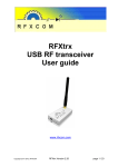
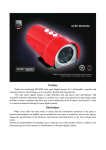
4.Special comments
Even the most sophisticated detcetors can sometimes be defeated or may fail to warn due to :DC power failure/improper connection, malicious masking of the lens,tampering with the optical system, decreased sensitivity in ambient temperatures near that of the human body and unexpected failure of a component part.The above list includes the most common reasons for failure recommended that the detector and the entire alarm system be checked weekly, to ensure proper performance.An alarm system should not be regarded as a substitute for insurance. Home & property owners or renters shouldbe prudent enough to continue insuring their lives & property, even though they are protected by an alarm system.
This device has been tested and found to comply with the limits for a Class B digitaldevice, pursuant harmful interference in residential installations .This equipment
generates,uses and can radiate radio frequency energy and ,if not installed and used in accordance with the ins-tructions ,may cause harmful in-terference to radio and television reception. However, there is no guarantee that interference will not occur in aparticular installation .If this device does cause such interference , which can be verfied by turning the device off and on ,the user is encouraged to eliminate the interference by one or more of the followingmeasures:
- Increase the distance between the device and the receiver.
- Connect the device to an outlet on a circuit different from the one that supplies power to the receiver.
- Consult the dealer or an expericnced radio/TV technician.
Installation Guide of FT-85
PIR & MW Intelligent Intrusion Detector
1. Introduction
FT-85 is virtually the best outdoor/indoor motion detector ever presented, for industrial, commercial and residential security. FT-85 has a m as sive
aesthetic design and combines the technologies of passive infrared and Microwave as well It is waterproof and all-weather resistant. FT-85 also alerts in any attempt to damage disable its operation . Ft-85 combines a variety of detection techniques that enable it to work in the most difficult
environmental conditions and where high security is required while maintaining unprecedented immunity to false alarms. The two synchronized
PIR sensors produce a three-dimensional thermal imaging of the protected area. Combining the fourth dimension ad microwave scanning contributes
to an amazing detection capacity and at the same time it also increases the reliability and immunity to false alarms. Using this technique allows high
WARNING! Changes or modifications to this unit not expressly approved by the party responsible for compliance could
void the user s authority to operate the equipment.
sensitivity level adjustment in both detection technologies without the need of pulse count. In addition to an unprecedented amazing and reliable
detection skill, FT-85 is equipped with unique protection mechanisms against any attempt to damage or to disable its operation. These following
protection mechanisms always work-weather the alarm system is Armed or Disarmed:
5
1.Forntal Anti-masking by a continuous active infrared scan, against masking the near field-of-view of the detector (Detects even transparent objects
Solution of usual problem
such as clear glass, plastic bags or transparent spray of any king)
2. Imposes OR mode in distress. If from any reason, the PIR detection channel is neutralized(for example, the detector front was masked) the Micro-
In alarm area, have walk test but no alarm output
wave detection channel will guard the protected area.
OK
Alarm LED lights up,
without alarm signal
output
To check the detector
working voltage is at
9-16V/DC or not
NG
OK
OK
To adjust the working voltage of
the detectorto 9-16 V/DC
OK
To check if the control main
board faulty. If yes, contact
the supplier of mainboard.
Please clear the trouble of short-circuit
To reset the detector, check
the LED lights up or not
OK
Repeat walk test
OK
False alarm
Check the voltage of power
supply. DC 9-16V
If there is strong cold or hot airflow in
the detection area. such as from air
conditioner, heater, etc
OK
NG
To adjust the power supply voltage
to DC9-16V at certain redundancy.
OK
Unstable installation base
NG
To select new installation base,
choose solid foundation
To get rid of cold or hot airflow, or change installation environment.
To remove the over 20kg animal
Installation height do not at 1.8-2.4m,.
Especially, less than 1.8m
To adjust installation height according
to the instruction
The detector's sensitivity is too high
To adjust the sensitivity and repeat walk
test
If there is high voltage electric field near
to the wire of detector
To adjust the position of installation to
make sure it is far away from the highvoltage electric field.
Wire terminal bad connected, with high
resistance
OK
NG
Check the power OK
input connection
is correct or not
NG
Open the LED switch
Check if the voltage is at
DC9-16V or not, according to the manual
OK
OK
Ensure power input
connection right
Check power supply
system at DC9-16V
NG
Short circle or wrong earth connection in power supply, get rid of the
mistake
2005 copyright
C
P/N82605002C
OK
Disconnect the terminal to check the power supply system
NG
8
6
4
2
0
2
4
PIR Section:Lens Date
NO.of Curtain Beams
(11+11+9)*2=62 (Typical)
Max.Coverage 1 2 *1 2 m /90
Tripping Indication:
3 colour lights for about 30 seconds
6
8
Sise View
M i crow a v e
Alarm ,Mask and Tamper
0 2 4 6 8 10 12m
Alarm Output:
Solid-state relay, N.C & N.O up to 100mA/30V,-30
Tamper Contacts: N.C , 50mA resistive /30 VDC
Mask Output: N.C up to 100mA/30V,-30
Accessories:
BR-1:Surface mounted swivel bracket, adjustable 30
down and 45 left or right.
Environment:
Operating Temperature: -10 C to 50 C(14 F to 122 F )
Storage Temperature :-20 C to 60 C (-4 F to 40 F)
Anti white light : 9 0 0 0 LUX
Physical
Size(H*W*D): 176*83*66 m m
This device is coherent to Europe parliament direct 1999/5/EC
necessary items and rules, and also coherent to the main spirits
of radio and telecom terminal equipments on March 9 th . 1999.
The device also reaches the Canadian standard RSS-210. It can
be used indoor and outdoor, which can reach its maximum protection and avoidance of above interference.
3.Installation
3.1 General Guidelines
Change the power supply or repairing
Please send E-mail
export @meiantech.com for Tech Support
If the power supply
circle is open
NG
Mounting
Surface or corner,at the height of 1.8 to 2.4 m
Note: Base allows single-sided corner mount at 45 to wall
Wire terminal well connected
With electronic power on, no LED signal
If the LED switch
off or not
Top View
Models
FT-85;
FT-85DMF;
FT-85DMT
Detection Range: 12m
Input Voltage:9 to 16 VDC
Current Drain:About 65mA @ 12 VDC
2
If there is animal more than 20Kg in the
detection area.
Output of power supply not good, not
good filtering
2.Specifications
M ic r o w a v e
Alarm LED shut off,
without alarm signal
output
To open the detector
OK To disconnect the alarm
output wire from the terminal,
cabin, check the relay
check if there is short circuit
contact is open or not
NG
NG
Please send E-mail
export @meiantech.com for Tech Support
NG
3.Anti-case-shifting, by inertial switch that alerts if someone shifts, moves or turns the detector.
To connect power supply
circle correctly
Don't face cold
or heat directly
Don't face the sunshine directly
Wire connection or
detector can't be near
to high-pressure cable
Don't install on a
unstable base.
Don't face metal wall
3.2Anti-pests installation
The wire length of power
supply is exceeded, or wire
diameter is too small. Please
change into fitted wire.
Power supply system has problem,
need to be repaired or contact the
power system supplier
The upper part of the
detection area is non
anti-pests area
Never face the detector to
the place that pests can
climb up directly
Anti-pests weight
20Kg
The installation height
of the detector is 2.2-2.4
meters can Anti-pests
3.3Illustrated Installation Procedure
3.3.1
3.3.2
Mount base
3.9
Setting of detection angle
Disassemble unit
E.Remove the PCB
C.Move the cocer to the
volitant top and remove it
D.Loose the screw
1.8-2.4m
6-8ft
A. Mark the drilling points
and drilling the wall
above ground
B. Route the wires into the
base VIA the rear channel
Surface
mount
C. Insert two dowels and
attach the base to the wall
with two screws
When multi-function bracket
is used (optional), installation shad refer to the right diagram, adjust installation angle, in order to get needed detection scale and function
D.Insert the bottom edge of
the large PCB under this
TAB & Press the top edge in
A.Loose the screw
B.Pull out the bottom
of the cover
3.4
Single side 45
angled side
3.5
MW sensitivity adjust
At this angel, sensitivity
is in middle. Pet immunity up to 10Kg animal
3.10
3.11
Adjust the PCB:
1.1m
3.1m
NO
Function
OFF
ON
1
LEDs
OFF
ON
2
PIR Sensitivity
LOW
HIGH
3
Anti-masking&
Anti-case-shifting
Sensitivity
4
Detection Combination Type
5
Anti-case-shifting
Enabling
1.1m
Notice:Adjustment of MW detection scale should meet the size of
protected room.
3.6
Product operates its relays and LED indicators
according to the detection nature as following:
TYPE OF
DETECTION
LED INDICATORS
Alarm-true motion
detection
Red +Green
blinking together
ALARM relay will activate
for 2 seconds
Green
NO relay will operate
PIR detection
OR mode
MW
detection AND mode
Red
Red + Green
blinking together
(During masking
only!!!)
Anti-masking
detection
Yellow
Blinking
Anti-case-shifting
detection
ALARM relay will activate
for 2 seconds
If masking exists for more than 2
minutes, the green LED will glow
constantly ,and the MASK relay
will operate for at least 2 seconds
and all time the masking exists
MASK relay will activate
for 2 seconds
3.7 .Extremity connection
Alarm area
EOL
resistor
Alarm control panel
24H Tamper
area
Mask
Tamper
area
MW mask
3.1m
LOW
HIGH
Microwave
AND PIR
Microwave AND
PIR OR Just
Microwave (During
masking only!!!)
ENABLED
DISABLED
When detector is installed
in different environment
and places, you can solve
the problems you meet through adjustment of the
position of PCB, eg: when
detector installed on 1.1 m,
you need to adjust the marks
on PCB to 1.1m position.
And also as you install the
detector to t3.1 m, adjust
the PCB to 3.1 m, usually it
is 2.1m, ie, at the middle.
1.1m
3.1m
RELAY STATUS
NO relay will operate(During
masking only!!!)
Alarm area
OR
Alarm area
EOL
resistor
When control panel is set to
extremity operation mode.
please try extremity resistor.
At this angle, detection
angle is smallest, sensitivity is highest. no pet
immunity function.
DIP Switch Adjustment:
MW sensitivity adjust
Turn MW scale regulating
wheel to the anticlockwise
direction and adjust the MW
detection scale to the Min, During
walking test adjust the wheel to clockwise direction and gradually increase
the MW detecting scale till the whole protection area is covered.
At this angle, detection angle is
largest, Lower section sensitivity
is low. Pet immunity up to 20Kg
animal
3.8 Wiring terminal specifications
Termindls8+9
Indicated on the circuit as:- +
These are the 12V DC power supply inputs
Terminals 5+6+7
Indicated on the circuit as: ALARM (C/N.C./N.O)
Represent the contacts of the (Alarm Relay)
C+N.C.=Normally Closed. C+N.O=Normally Opened.
Upon any human movement detection, the relay's contacts are Opened
for two seconds.
Terminals 2+3
Indicated on the circuit as: ( MASK)
Represent the contacts of the (Masking Relay)which normally are in closed state(N.C.). Closed state(N.C). If an object blocks(masks)the near
field-of-view of the detector for more than 2 minutes, the green LED will
glow constantly, and the( MASK) elay will operate for at least 2 seconds
and all time the masking exists
Terminals 1+2
Indicated on the circuit as ( TAMP)
Represent the contacts of the built-in TAMPER switch, which are normally
in closed state(N.C.) The contacts will open, upon the detector's case is
opened.
Terminal 4
Indicated on the circuit as ( CO) .
This terminal to be used if you wish to get a report from the detector's
memory , whether it has detected human movement during the armed
period. This terminal should get indication from the alarm system's control
panel, whether it is in Armed or Disarmed state.
-If 0V received, the detector (understands) <
-If 12V or no voltage at all received, the detector (understands)
That the alarm system is Disarmed.
How to draw and display the detector's memory?
If: the detector has alerted during the (armed) period,
Than: upon switching the alarm system from (Armed) to
(Disarmed) mode, the Red LED will be activated for 30 minutes.
3.12
Perform motion test to the detection area:
1. Start the test at least 2 minutes after power supply
2. Crossing to any direction of the detection area, your walking with
0.75m/s will cause the Red&Yellow LED indicator to light for 2-3
seconds (refer to the right diagram)
3 .Perform motion test from contrary directions in order to confirm
the boundary of two sides. Make confirmed that detection center
pointing to the center of protected area.
4. Away from the detector 3 to 6 m, raise slowly your arm and reach
into the detection zone, mark the lower limit of PIR detection. Do
the same step to confirm the upper limit.
5.the center of detection zone should not uphill incline. To obtain a
good detection range , please adjust the vertical detection range, ensure the detector is in a correct position.
6. After MW sensitivity or detection angle are adjusted, walking test
must be performed according to the above steps.
The test procedure for masking detection (Anti-masking):
In a distance of about 10 cm from the detector's front,place a white paper
(or any other object).
The necessary reaction of the detector:
The Yellow LED will blink immediately.
After 2 minutes the (asking Relay )will activate.
All time when an object blocks(masks)the near field-of-view
of the detector, the masking relay and the Yellow LED will activate
The test procedure for Case-shifting detection:
Shake the detector.
If it fixed to a wall, knock on the detector's case by ascrew driver.
The necessary reaction of the detector:
The(Masking Relay)will activate for 2 second.
The Green LED will activate, shortly, upon every knocking.
Important mention: Motion test shall be performed at least one time each
week in order to guarantee that each detector can keep excellent function.
Preparing the Anti-Masking channel for work
In order to enable the masking detection to operate properly, it is Necessary
to allow the detector study and analyze automatically the environmental
conditions of its protected area.
The study procedure to be performed in three cases:
1.Upon connecting the power supply to the detector.
2.Upon the position of DIP switch number-3(Masking detection Sensitivity)
is changed.
3.Upon relocation of the internal unit of the detector.
The study procedure in the first &third case:
-Close immediately the detector's case (within 15 seconds Maximum).
-Keep away (at least 0.5 meter )from its front ,until the study
Procedure finished, about 30 seconds.
-As an indication for the study procedure,the Red+Yellow LEDs
will blink rapidly once the procedure begins and ends.
The study procedure in the second case:
-Change the position of DIP switch number-3 for about one second, and
switch it back to the original place.
-Close immediately the detector's case (within 15 seconds maximum).
-Keep away (at least 0.5 meter )from its front,until the study procedure
finished,about 30 seconds.
-As an indication for the study procedure, the Red+Yellow LEDs will
blink rapidly once the procedure begins and ends.