1
User Manual
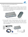
(3)Function Test: Power on your PC, the Transmitter will take the power
from the PC’s PS/2 connection; the front PC ON LED of Transmitter
will keep blinking on green to indicate the unconnected status of
System Link and the LEDs above RJ-45 will turn on to indicate the
activation of video signal. Please test the function of monitor display,
and make sure the keyboard and mouse are working properly to
finish the installation of Transmitter unit.
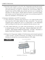
2. Receiver Installation and UTP Connection:
(1) Site Selection: Please place Receiver in an appropriate place
and have the UTP cable settled for later connection. You can use
magnetic pad to attach the unit on a metal plane or use attachable
rack mounting kit to fix the unit on selected area by screw or nail.
(2) UTP Cable Selection: For best VGA performance, you can refer
to following type of UTP Cat5 cable - Belden DataTwist 350 UTP #1700A – Solid, Belden DataTwist 350 patch - #1752A – Stranded, or
Belden DataTwist Category 5e – 1583A – Paired cable
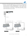
(3) Power On: Plug power adapter to the Receiver and connect keyboard
/ video monitor / mouse to Receiver, the LEDs of unit should keep
blinking to indicate the unconnected status of UTP cable.
Receiver
AC7.5v Power Adaptor
Video Control
Installation of Receiver