1
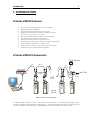
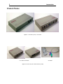
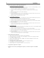
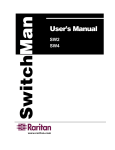
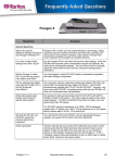
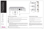
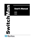
Copyright © 2002 Raritan Computer, Inc. Z4200U-0C April 2002 Raritan Computer Inc. 400 Cottontail Lane Somerset, NJ 08873 USA Tel. 1-732-764-8886 Fax. 1-732-764-8887 E-mail: [email protected] http://www.raritan.com Raritan Computer Europe, B.V. P.O. Box 566 2900 AN Capelle aan den IJssel The Netherlands Tel. 31-10-284-4040 Fax. 31-10-284-4049 E-mail: [email protected] http://www.raritan.com Raritan Computer Japan, Inc. Kuga Building 7F 11-6, Kuramae 4-chome Taitoo-ku, Tokyo 111-0051, Japan Tel. 81-3-5833-6360 Fax. 81-3-5833-6336 E-mail: [email protected] http://www.raritan.co.jp Raritan Computer Taiwan, Inc. 5F, 121, Lane 235, Pao-Chiao Rd., Hsin Tien Taipei Hsien, Taiwan, ROC Tel. 886-2-8919-1333 Fax. 886-2-8919-1338 E-mail: [email protected] http://www.raritan.com.tw I FCC Information FCC Information This equipment has been tested and found to comply with the limits for a Class A digital device, pursuant to Part 15 of the FCC Rules. These limits are designed to provide reasonable protection against harmful interference in a commercial installation. This equipment generates, uses, and can radiate radio frequency energy and if not installed and used in accordance with the instructions, may cause harmful interference to radio communications. Operation of this equipment in a residential environment may cause harmful interference. Product names mentioned in this document are trademarks or registered trademarks of their respective companies. Z-Series, Paragon, MasterConsole MX4, MasterConsole MXU2, MasterConsole II, MasterConsole SMX, and their respective logos are registered trademarks of Raritan Computer, Inc. PS/2, RS/6000, and PC/AT are registered trademarks of International Business Machines Corporation. Sun is a registered trademark of Sun Microsystems. All other marks are the property of their respective owners. Table of Contents II Table of Contents FCC INFORMATION I TABLE OF CONTENTS II 1. INTRODUCTION 1 2. IMPORTANT CABLE INFORMATION 4 3. INSTALLATION 5 Quick Start 5 Installing More Computers 7 Installing Local User Console to UKVMSC 8 4. OPERATING Z4200U 9 APPENDIX A: UTP CABLING FAQS 13 APPENDIX B: PARAGON DIRECT CONNECT 15 APPENDIX C: SPECIFICATIONS 16 APPENDIX D: FAQS 17 APPENDIX E: TROUBLESHOOTING 18 GLOSSARY 19 Introduction 1 1. INTRODUCTION Z-Series Z4200U Features Innovative Zero-U design supports up to 42 computers Simple plug and play installation Add a computer anywhere in the chain at any time Keep-alive keyboard/mouse emulation for flawless operation Hot connect a user console to any server Hot-swap components with no impact on server operation User Station supports PS/2 or Sun keyboard Select computers by name from on-screen menus Automatic Video Tuning (AVT) adjusts video quality automatically Supports high-resolution video—to 1600 x 1200 Locate user up to 1,000 feet away with Category 5e UTP cable Admin. Port for on-site, flash firmware upgrades Z-Series Z4200U Components t5 e Cat 5e UKVM SPD UKVMSPD UKVM SPD UKVMSPD USTS Ca User Console Z-CIMs Cat 5 Cat 5e Cat 5e e Z-CIM Terminator Last Z-CIM IN OUT PC UKVMSC Z-CIMs Up to 42 Z-CIM Servers Up to 42 Figure 1 Z4200U Basic Configuration A Z-Series Z4200U “switch less” access system consists of two components – a User Station (USTS) (Figure 2) and a Z-Series Computer Interface Module (Z-CIM) (Figure 3), - connected with Enhanced Category 5e UTP cable. The Z-CIMs are linked in a chain via Category 5e UTP cable. Servers are connected to each of the Z-CIMs. 2 Introduction Product Photos Figure 2. User Station (USTS) – Front & Back Front & Back of UKVMSC Figure 3. Z-Series Computer Interface Modules (Z-CIMs) UKVMSPD Introduction 3 User Station (USTS) Port and Control Descriptions Front Panel • • Status LED: Indicates power and operational status of USTS User Station Up / Down Buttons: Physical controls to switch between connected computers, in alphabetical order by computer name. Pressing UP switches to the previous computer by name. Pressing DOWN switches to the next computer by name. See Section “4. Operating Z4200U” for more information about channel switching and channel naming procedures. Back Panel • • • • • • • • 6VDC: For connection of 6V DC power supply (provided). Sun K/B: Not currently supported. For connection of Sun keyboard to operate USTS. PS/2 K/B: For connection of PS/2 keyboard to operate USTS. Video HD15: For connection of multisync VGA monitor to view connected computers. PS/2 MS: For connection of PS/2 mouse to operate USTS. Cat5: For connection of up to 42 computers, using Cat5 UTP cable and a chain of Z-Series computer interface modules (CIMs). Video Adjustment: Adjusts video gain/amplification, to eliminate video ghosting or shadowing in Z-series configurations employing long distance video runs (250 feet or more), or unusually high refresh rates. Admin: Proprietary serial port used to upgrade USTS firmware. When available, new firmware will be posted on Raritan website http://www.raritan.com. Installation 4 2. IMPORTANT CABLE INFORMATION Raritan certifies the following Category 5e UTP and Category 6 UTP cable products for use with the Z-series Z4200U system: Certified Cables for Use with Raritan Products Category 5e UTP Cable: Category 6 UTP Cable: Belden DataTwist 350 UTP Belden DataTwist 350 patch Belden MediaTwist #1700A #1752A #1872A Solid Stranded Solid Use of non-certified cabling can result in video and data degradations that users may find unsatisfactory. Certified Raritan cable products listed above are widely available and competitively priced. When using certified cable, users can transmit video signals at distances up to 1,000 feet at 1024x768 @75Hz. Note: Raritan does not have any marketing relationship with Belden, nor does Raritan receive any financial incentive for recommending Belden products. Figure 4. Cable Pin-out Requirements See Appendix A: UTP Cabling FAQs for more information on Raritan certified cables. Installation 5 3. INSTALLATION Z-CIM (UKVMSPD) Cat 5e Cat 5e Back of USTS Sun PS/2 Video MS Cat 5 Video Admin e t5 Ca Adjustment U K VM SP D KB PS/2 Z-CIM Terminator Z up -CI to Ms 42 Last Z-CIM U K VM SP D DC Power Adapter K/B Video Mouse K/B Video Mouse Servers up to 42 User Console Figure 5. Z4200U Installation Quick Start Note: All computers and all Z4200U components must be powered OFF prior to installation. Note: Z-Series installation requires that each computer be assigned a channel name as it is added to the Z4200U chain, adhering to the order of the installation steps that follow. Computer channels are organized alphabetically by assigned name (or the default name which is the Z-CIM’s serial number), rather than in the order of their placement within the Z4200U chain. Installers that first connect all computers and then attempt to assign channel names will have difficulty locating the respective channel for each computer. 1. Install USTS (Figure 5): • Connect DC power adapter to the User Station (USTS), and plug into AC power source. • Connect a PS/2 keyboard, mouse and VGA monitor to appropriate User Station (USTS) ports. • Plug in and power ON monitor • A blank Selection Menu (Figure 9) will appear on the user console monitor. The message banner across the bottom will say “Searching.” Note: Installation requires basic operation of the On-Screen User Interface (OSUI) menus. Rapidly pressing the default Hot Key activator <Scroll Lock> twice activates the OSUI. Function keys <F1>, <F2>,<F3>, and <F4> are used to switch among menus. Pressing <F1> while OSUI is active invokes the Help Menu (Figure 8). This menu lists all available menu options. Whenever the OSUI is invoked, the user console keyboard’s <Scroll Lock> LED indicator blinks. Section 4. Operating Z4200U gives more detail on OSUI menus and operations. Menu Title Z-Series OSUI Main Body ….. Scrolling or single-line message ScrollLock | Scan Figure 6. OSUI Display | banner….. NCS 6 Installation 2. Connect One Computer to USTS using Z-CIM (Figure 5): For UKVMSC Z-CIM (Figure 3) with local port: • Connect DB25 male end of CCPxx cable to DB25 female port on back of a Z-CIM (UKVMSC). Connect other end to computer’s keyboard, video, and mouse ports. • Connect a Category 5e UTP cable to the UTP OUT port on the Z-CIM (UKVMSC). • Connect the other end of this Category 5e UTP cable to the RJ45 Cat 5 port on the User Station (USTS). • Place the Z-CIM Terminator in the Z-CIM’s UTP IN port. • Power ON computer. • A factory name and serial number for the Z-CIM will display on the Selection Menu of the User Console attached to the USTS. This represents the connected computer. • Optional: See page 7 to install a local user console. For UKVMSPD Z-CIM (Figure 3) : • Attach the Z-CIM to the computer via its HD15 port. Connect the 6-pin mini-DIN keyboard and mouse connectors on the Z-CIM to computer’s keyboard and mouse ports. • Connect a Category 5e UTP cable to the UTP OUT port on the Z-CIM (UKVMSPD). • Connect the other end of this Category 5e UTP cable to the RJ45 Cat 5 port on the User Station (USTS). • Place the Z-CIM Terminator in the Z-CIM’s UTP IN port. • Power ON computer. • A factory name and serial number for the Z-CIM will display on the Selection Menu of the User Console attached to the USTS. This represents the connected computer. For UKVMSP Z-CIM: • Connect the 6-pin mini-DIN keyboard and mouse, and HD15 video connectors on the UKVMSP Z-CIM to computer’s keyboard, mouse, and video ports. • Connect a Category 5e UTP cable to the UTP OUT port on the Z-CIM (UKVMSP). • Connect the other end of this Category 5e UTP cable to the RJ45 Cat 5 port on the User Station (USTS). • Place the Z-CIM Terminator in the Z-CIM’s UTP IN port. • Power ON computer. • A factory name and serial number for the Z-CIM will display on the Selection Menu of the User Console attached to the USTS. This represents the connected computer. 3. Name Computer & Test Operation • While viewing the Selection Menu, press <F3> to open the Edit Menu. • The Edit Menu (Figure 10) will display, with a yellow highlight on the name of the computer just added. • Press <Enter>. Highlight turns green • Type in a desired computer name and press <Enter> when completed. Highlight area will turn yellow. • Press <S> to save the new name. • Press <F2> to return to the Selection Menu. • The Selection Menu will display with the new computer name highlighted in white. • Press <Enter> to switch to this selected computer. • Normal computer access and operation indicates a successful connection. 4. Congratulations! Quick Start is complete 5. Proceed to the next section, “Installing More Computers,” to add more computers to the Z4200U chain. Installation 7 Installing More Computers Repeat steps 1 through 3 below to add computers to the Z-Series Z4200U chain. Name and test each computer as it is added. Note: Z-Series Z4200U installation requires that each computer be assigned a channel name as it is added to the 4200 chain, adhering to the order of the installation steps that follow. Computer channels are organized alphabetically by assigned name (or the default name which is the Z-CIM’s serial number), rather than in the order of their placement within the Z4200U chain. Installers that first connect all computers and then attempt to assign channel names will have difficulty locating the respective channel for each computer. Note: All newly added Z-CIMs and computers must be powered OFF prior to installation. 1. Attach Z-CIM to computer to be added For UKVMSC Z-CIM (Figure3) – with local port: • Connect CCPxx cable’s 6-pin mini-DIN and HD15 connectors to computer’s keyboard, mouse, and video ports. • Connect DB25 male end of CCPxx cable to DB25 female port on back of Z-CIM (UKVMSC). For UKVMSPD Z-CIM (Figure 3): • Attach the Z-CIM to the computer via its HD15 video port. Connect the 6-pin mini-DIN keyboard and mouse connectors on the UKVMSPD Z-CIM to computer’s keyboard and mouse ports. For UKVMSP Z-CIM: • Connect the 6-pin mini-DIN keyboard and mouse, and HD15 video connectors on the UKVMSP Z-CIM to computer’s keyboard, mouse, and video ports. 2. Attach Z-CIM to Z4200U chain • Remove Z-CIM Terminator from the last Z-CIM’s UTP IN port and set aside. • Connect a Category 5e UTP cable to the UTP IN port on the Z-CIM that is currently last in the chain. • Connect the other end of this Category 5e UTP cable to the UTP OUT port on the next Z-CIM/computer currently being added to the chain. • Place the Z-CIM Terminator in the added Z-CIM’s UTP IN port. • Power ON computer. • Press the default hot key <Scroll Lock> twice rapidly at the USTS User Console to bring up the On-Screen User Interface (OSUI). • Press <F2> to bring up the Selection Menu. • The new computer will appear as a new channel on the Selection Menu at the User Console of the USTS. A factory name and serial number for the Z-CIM will display. • Optional: For a UKVMSC see page 7 to install a local user console. 3. Name Computer & Test Operation • At the Selection Menu, press <F3> to bring up the Edit Menu. • The Edit Menu will display, with a yellow highlight on the name of the computer just added. • Press <Enter>. Highlight turns light green • Type in a desired computer name and press <Enter> when completed. Highlight area will turn yellow. • Press <S> to save the new name. • Press <F2> to return to the Selection Menu. • The Selection Menu will display with the new computer name highlighted in white. • Press <Enter> to switch to this selected computer. • Normal computer access and operation indicates a successful connection. 8 Installation Installing Local User Console to UKVMSC • • • Connect local user console (keyboard, mouse, and monitor) to UKVMSC’s local ports (Figure 7) to enable direct access to a computer locally. Connect optional DC power adapter (p/n A10D1-06MP) to UKVMSC, and plug power cord into AC outlet. Plug in and power ON monitor. Front of UKVMSC Figure 7. Connecting A Local User Console to a UKVMSC Z-CIM Operating Z4200U 4. 9 OPERATING Z4200U On-Screen User Interface (OSUI) Functions The Z2400U On-Screen Interface allows you to control, configure, and operate all facets of Z-series functionality. Press <Scroll Lock> twice rapidly to invoke the OSUI. Press… When you want to… <F1> View the Help Menu (Figure 8) – list all function keys. <F2> View the Selection Menu (Figure 9)—list of available channels, serial numbers, and scan rates. Selection Menu is used to switch between selected channels to access computers. <F3> View the Edit Menu (Figure 10) – change computer name or scan rate. Can also be used to designate the <Home> computer/channel. <F4> View the System Profile Menu (Figure 11)—view and change user-specific operating parameters <F6> Toggle scan on/off. The bottom of the OSUI menu indicates that the Scan function is ON when the word “Scan” is highlighted in yellow. <F11> Reset User Station - Reloads USTS – searches all connected Z-CIMs, updating all user names and IDs <Esc> Exit the OSUI Help Menu The Help Menu (Figure 8) lists all the functions keys for quick and easy reference. Figure 8. [F1] Help Menu 10 Operating Z4200U Selection Menu The Selection Menu (Figure 9) lists channels, serial numbers, scan rates, and the number of servers currently detected by the system, sorted by computer name in alphabetical order. Use the <↑>, <↓>, <PageUp> or <PageDown> keys to select a channel. Press <Enter> to switch to the selected computer/channel. Figure 9. [F2] Selection Menu Alternatively, you may switch between computers without using the OSUI, by using the UP and DOWN buttons in the front of the USTS user station. These buttons switch between computers by name in alphabetical order: UP switches to the previous computer by name in alphabetical order; DOWN switches to the next computer by name in alphabetical order. Edit Menu The Edit Menu <F3> (Figure 10) can be used to make changes to the computer channel name and its scan ratethe time interval, in seconds, that a channel’s computer is to remain displayed on monitor during scanning. It can also be used to designate a channel as a <Home> computer. 1. Press < >, < >, <←>, or <→> to highlight (in yellow) the field to be edited 2. Press <Enter>. Highlight turns green. 3. Edit name and/or scan time. 4. Press the <Home> key if you wish to designate this computer/channel as your home computer. An “H” will appear in the right most column. This designation will enable the user to quickly select or switch directly to the home computer. At the Selection Menu, pressing the <Home> key once highlights the home channel. With no OSUI displayed, rapidly pressing the <Home> key twice automatically switches the user to the computer designated as the home computer. 5. Press <Enter> when completed. Highlighted area will turn yellow 6. Press <S> to save changes and exit, or <ESC> and then <N> to exit without saving changes. 7. Press <F2> to return to Selection Menu. 8. Verify that new name appears on Selection Menu in green. Operating Z4200U 11 Figure 10. [F3] Edit Menu 12 Operating Z4200U System Profile Menu The System Profile Menu <F4> (Figure 11) can be used to make changes to parameters that effect overall system functionality. Select fields to be edited by pressing <Tab> (moves forward) <Shift-Tab> (moves backward), < >, < >, < >, or < > keys to move to desired field. Press <Enter> to begin editing. Highlighted area will turn green. Use the < >, < > keys to select choices in each field or make entries as explained below. Press <Enter> when editing is done. Highlighted area will turn from green to yellow. Press <S> to save changes, and <ESC> to exit System Profile Menu. To exit System Profile Menu without saving changes, press <ESC> and then <N> or <ESC> again. Figure 11. [F4] System Profile Menu • Scan Mode: By pressing <F6> to toggle ON scan mode, the user station can scan through all attached computer channels at a specified time interval. Global or Individual scanning is available. Default setting is Global. When scan mode is activated the word “Scan” at the bottom of the OSUI is highlighted in yellow. − Global: − Individual: Scans each channel for the specified time set per channel, as shown in Selection Menu. (Setting each channel’s individual scan rate is a function of the Edit Menu <F3>, where individual channel scan times can be set between 03 and 30 seconds. Default is 03 seconds.) Scans each channel for the same amount of time, as indicated under Global Scan Rate. • Global Scan Rate: Sets the time duration for which each channel will be scanned. Use the < > and < > keys to set between 03 and 30 seconds. Default setting is 03 seconds. • ID Display: The ID Display is a small window that shows computer name when switching or scanning between channels. Two fields control it: − On/Off: Use < > and < > keys to toggle between on and off. − Time: Use < > and < > keys to increment or decrement the desired time period. A “- -“ indicates the ID window will be shown all the time. Default setting is On/03 seconds. Operating Z4200U • 13 Green Mode (PowerSave Mode): Blanks the screen if the user console is idle for a pre-specified amount of time. Two fields control it: − On/Off: Use < > and < > keys to toggle between on and off. − Time: Use < > and < > keys to increment or decrement. Default setting is Off/03 minutes. • Display Position: For changing the position of the On-Screen Menu and ID Display Window. Highlight Menu or ID and hit <Enter>. Use < >, < >, < >, and < > keys to change position. Press <S> to save. • Hot Key: Use < >, < > keys to select <ScrollLock>, <CapsLock>, <NumLock> or <Left-Alt> or <Left-Shift>. Default setting is <ScrollLock>. Rapidly pressing selected Hot Key twice activates Z4200U’s On-Screen User Interface (OSUI). • Previous Channel Key: Use < >, < > keys to select <ScrollLock>, <CapsLock>, <NumLock>, <Left-Alt> or <Left-Shift>.. Default setting is <NumLock >. Rapidly pressing the selected Previous Channel key twice enables user to go back to previously selected computer without going through the OSUI. NOTE: Previous Channel Key and Hot Key cannot share the same key selection. • Scrolling Help: Use < > and < > keys to toggle between on and off. The message banner can be displayed as scrolling (On) or non-scrolling (Off). Default is On (and scrolling). 14 Appendix A: UTP Cabling FAQs Appendix A: UTP Cabling FAQs Cat5 / Cat5e / Cat6 Cabling FAQ Answer: Question: What UTP cable does Raritan recommend for use with Paragon, Paragon ReadyTM, and Cat5 ReachTM products? Raritan certifies the following Category 5e UTP and Category 6 UTP cable products for use with its family of industry-leading data center solutions: Certified Cables for Use with Raritan Products Category 5e UTP Cables: Category 6 UTP Cables: Belden DataTwist 350 UTP #1700A Belden DataTwist 350 patch #1752A Belden MediaTwist #1872A Solid Stranded Solid Use of non-certified cabling can and will result in video and data degradations that users may find unsatisfactory. Certified Raritan cable products listed above are widely available and competitively priced. When using certified cable, users can transmit video signals at distances up to 1,000 feet at 1024x768 @75Hz; and up to 600 feet at 1600x1200 @75Hz. Note that Raritan does not have any marketing relationship with Belden, nor does Raritan receive any financial incentive for recommending Belden products. Can I use plain Cat 5 cable, instead of Cat 5e? Yes, however, you may not get the same performance as you would with Raritan certified Category 5e UTP or Category 6 UTP cables. Standard Category 5 UTP cable may not have the necessary characteristics for transmitting high-quality video over long distances. Can I use standard Ethernet (10BASE-T) cable? No. Standard Ethernet cable does not have the necessary bandwidth characteristics for transmitting high-quality video over long distances. Can I use non-certified Cat 5e cable? Yes, however, you may not get the same performance as you would with Raritan certified Category 5e UTP or Category 6 UTP cables. Using noncertified Category 5e UTP cable with Raritan products results in degraded video performance ranging from mildly irritating to severely unusable. The only occasion when a non-certified cable may be used with Raritan products without negative effects on system usability is when the total cable distance between any user console and any connected device is less than 300 feet. Because cable products certified by Raritan do not cost more than competing cable offerings, Raritan strongly recommends that users utilize Raritan certified cables for maximum performance with Raritan product applications. Can I use Cat 6 cable? Yes. Currently only one Category 6 UTP cable product is Raritan certified for use with Raritan products. Raritan continues to test new Category 6 UTP cabling products as they are released to the market. However, at the present time, no Category 6 standard currently exists; all products currently available in the marketplace claiming to be Category 6 UTP cable actually conform to a proposed standard, not an established one. As a result, great variation in cable types and performance exist. What happens if I do not use Raritan certified cable? Cable products that are not specifically certified by Raritan will likely cause your video to look blurry; in particular if the video signal is of high-resolution, or if the video signal must be transmitted over long distances. Furthermore, LCD monitors can become unusable Appendix A: UTP Cabling FAQs Answer: Question: Cat 5e is standardized. Why can’t I simply use any Cat 5e cable with Raritan products? 15 Because the intended application of UTP cabling is the transmission of digital data, cable specifications are optimized for that application. However, because video data is by its very nature analog, Raritan’s exclusive technology – which enables such high-bandwidth video information to be transmitted over relatively thinly-shielded Category 5 UTP and Category 6 UTP cables – requires even stricter tolerances for certain cable properties. One particular UTP cable characteristic has a large impact on how well your Raritan system performs: delay skew. UTP cabling consists of four “twisted pairs” of wire, each carrying one set of data. In order to minimize crossinterference between the pairs, each pair must be twisted at slightly different rates (twists/foot). Over long lengths of cable, however, slight differences in twist rates results in measurably different rates of data transmission among each twisted pair. The arrival time delta is called “delay skew.” How does this affect your Raritan solution? Raritan products send red, green, and blue video information each over a different twisted pair; if that information does not arrive at the same time, observed video will be blurry. Raritan’s unique algorithms correct for this behavior, but physical limitations create upper limits to the success of any algorithm. The TIA/EIA specification for delay skew tolerance is 45 nanoseconds for Category 5 UTP and Category 5e UTP cable. However, in analog video applications, a delay skew longer than 15 nanoseconds usually results in inadequate video performance at high resolutions (XGA and higher). Raritan-certified cable products happen to surpass the acceptable tolerances of the TIA/EIA’s specification for delay skew, and hence are best suited for connecting Raritan components. Are there special pin out requirements that I must use? Yes. Figure 12. Cable Pin-out Requirements 16 Appendix B: Paragon Direct Connect Appendix B: Paragon Direct Connect Z-Series Z4200U Z-CIMs are Paragon Ready™, for convenient, clustered access and control of high-density rack mounted servers in large-scale data centers. The USTS is not required. Simply connect the first Z-CIM in the chain directly to Raritan’s Paragon with a single Category 5e UTP cable. NOTE: Support for Paragon Direct Connect of Z-CIM requires Paragon UST1 firmware version 2K10 or higher, and UMT8 firmware version 2B1 or higher. Cat 5e Cat 5e UKVMSPD UKVMSPD UKVMSPD U KVMSPD Ca t5 e Cat 5e Cat 5e Z-CIM Terminator Z-CIMs Last Z-CIM IN OUT PC UKVMSC Z-CIMs Up to 42 Servers Up to 42 Back of UMT8 Figure 13. Installing a Z-Series Z4200U Chain Directly to a Paragon Z-CIM Appendix C: Specifications 17 Appendix C: Specifications User Station (Receiver) USTS Dimensions Weight Power 11.4” (W) x 10.1” (D) x 1.75” (H) 290mm (W) x 255mm (D) x 44mm (H) 4.3 lbs (1.9 kg) 100V/240V 50/60 Hz 5VA Z-Series Computer Interface Modules (Transmitters) UKVMSC (for PC) with local port Dimensions Weight Power (optional) Ports 4.3” (W) x 3.6” (D) x 1.0” (H) 108mm (W) x 91mm (D) x 25mm (H) 0.7 lbs (0.3 kg) 100V/240V 50/60 Hz 5VA RJ45 in & out, plus local PC KVM ports UKVMSPD (for PC) Dimensions Weight Ports 1.68” (W) x 3.5” (D) x 0.75” (H) 43mm (W) x 89mm (D) x 19mm (H) 0.4 lbs (0.16 kg) RJ45 in & out UKVMSP (for PC) Dimensions Weight Ports 2.44” (W) x 3.5” (D) x 1.0” (H) 62mm (W) x 89mm (D) x 25mm (H) 0.4 lbs (0.16 kg) RJ45 in & out 18 Appendix D: FAQs Appendix D: FAQs Question: Answer: What is the Z-Series Z4200U? Z-Series replaces the traditional KVM switch box with an innovative chain-like server-to-server arrangement, significantly reducing cable clutter. Small Computer Interface Modules (Z-CIMs) connected to the keyboard, video, and mouse ports of each server are linked with standard Category 5e UTP cable and transmit keyboard, video, and mouse signals to a User Station. A keyboard, monitor, and mouse plug into the User Station, enabling the user to select and control up to 42 servers via simple on-screen user interface menus. Since ZSeries components are plug and play, servers can be added at any time with no interruption of server operation. How is the Z-Series Z4200U unique? Raritan’s innovative Z-Series offers a switchless solution that enables access and control of multiple servers from a single user console (keyboard, monitor, and mouse), without consuming precious rack space. Z-Series Z4200U employs Raritan's unique communication technology to control up to 42 servers and eliminate the traditional KVM switch box and all hard-to-manage server-to-switch cable. It is designed to support the most challenging demands of server management where space is at a premium or where systems to be accessed are up to 1,000 feet away via Category 5 UTP cable. What are the components of a Z-Series system? A Z-Series system consists of two components: the User Station and Computer Interface Modules (Z-CIMs). Computer Interface Module (CIM)—connects to the keyboard, video, and mouse ports of each computer and provides failsafe computer access with Raritan’s dedicated keyboard/mouse emulation. Z-CIMs are linked one to the next with a single Category 5e UTP cable; the last Z-CIM in the chain is linked to the User Station. User Station—enables a user console (keyboard, mouse, and monitor) to select and control up to 42 servers via a simple, onscreen user interface. Can the Z-Series chain be added directly to Paragon without the USTS? Yes. Z-Series is Paragon Ready™, for convenient, clustered access and control of high-density rack mounted servers in large-scale data centers. Connect the first Z-CIM in the chain directly to Raritan’s Paragon with a single Category 5 UTP cable. See Appendix B: Paragon Direct Connect. Appendix E: Troubleshooting 19 Appendix E: Troubleshooting Problems And Suggested Solutions Problem The Z-Series chain is installed, but there is no indication of active computers on the Selection Menu (no green channels). Solution Be sure the computers are powered ON and that each Z-CIM requiring a power supply (UKVMSC with local user console) is also plugged in. Be sure the USTS is plugged in. Ensure that the Z-CIM Terminator is in place in the last Z-CIM’s UTP IN port. Ensure that the Z-Series chain has been constructed properly with regard to the Z-CIM’s IN and OUT UTP ports. A Z-Series chain is directly connected to a Paragon UMT8, however, there is no indication of active computers on the Selection Menu (no green channels). Ensure that the Z-CIM Terminator is in place in the last Z-CIM’s UTP IN port. I have located the second channel on the Selection Menu, but it is not connecting to the second computer in the Z-CIM chain. Computer channels are organized alphabetically by assigned name, rather than in the order of their placement within the Z4200U chain. The second channel on the Selection Menu represents the computer or channel name that is second alphabetically, not second physically in the chain. The mouse and/or keyboard do not respond properly. Make sure all UTP cables throughout the Z4200U system are category 5e UTP cable produced by the same cable manufacturer. See Appendix A: UTP Cabling FAQs for Raritan certified Category 5e UTP cable recommendations. The Z-CIM’s indicator light is flashing rapidly, rather than blinking steadily, after connection to the computer and the Z-Series chain. In addition, there is no indication of an active computer on the Selection Menu (no green channel). Ensure that the cables connected the Z-CIM to the computer, and the cables connecting the Z-CIM to the Z-Series chain, are connected properly and securely The video quality that I see is blurry, or exhibits color seperation and/or ghosting. 1. 2. Adjust the “Video Adjustment” control on the back of your USTS unit. If you are using long cable runs (250 feet or more), or very high refresh rates, be sure to use Raritan-certified UTP cabling (see Section 2. Important Cable Information) for more information 20 Glossary Glossary Active Channel A channel is active when a connected device is powered on. See also Channel. Channel There are up to 42 “channels” in a Z-series configuration. A channel represents the path to a certain computer on the Selection Menu. See also Active Channel and Inactive Channel. Computer Name (Channel Name) A label of up to 12 characters assigned by an administrator for a device connected to a Z-Series channel. Edit Menu For editing computer names, changing channel scan times, and assigning a home channel. Global Scan Rate Scan rate used for all channels when Scan Mode field in System Profile Menu is set to Global. See also Scan Rate. Green Mode A field in System Profile Menu for toggling PowerSave feature on and off. Home Channel The channel designated as the users Home computer via the Edit Menu <F3>. This designation will enable the user to quickly select or switch directly to the home computer. At the Selection Menu, pressing the <Home> key once highlights the home channel. With no OSUI displayed, rapidly pressing the <Home> key twice automatically switches the user to the computer designated as the home computer Hot Key For activating On-Screen User Interface (OSUI). To activate the OSUI, press the Hot Key twice rapidly -default <ScrollLock>. ID Display A single-line display shown on monitor to identify a channel that has just been selected. Individual Scan Rate Scan rate specified for each channel when Scan Mode field in System Profile Menu is set to Individual. Individual per channel scan rates are set in the Edit Menu. See also Scan Rate. Local Console Keyboard, monitor, and mouse (user console) plugged into local Z-CIM port. Menu A Z-Series On-Screen User Interface (OSUI) display. Menu F Keys Function keys for On-Screen User Interface (OSUI) menus. (<F1>, <F2>, …) PowerSave Allows a properly equipped monitor to operate in energy save mode. See also Green Mode. Scan Toggle Function key <F6> for activating AutoScan. Scan Mode Field in System Profile Menu. Can be set to either Global or Individual. Scan Rate Time interval –in seconds- that a channel’s computer is to remain displayed on monitor when AutoScan is activated <F6>. See also Global Scan Rate and Channel Specific (Individual) Scan Rate. Selection Menu On-Screen User Interface (OSUI) Menu used for selecting and accessing a computer or device. Terminator RJ45 Z-CIM terminating plug. To be inserted in the UTP IN port on the last Z-CIM in the Z4200U chain. User Console Keyboard, monitor, and mouse plugged into a user port on USTS back panel.