1
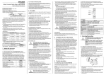
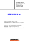
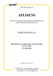
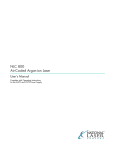
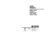
NLC 2270 Argon-ion Laser Power Supply User’s Manual TABLE OF CONTENTS CHAPTER 1: INTRODUCTION 1 CHAPTER 2: POWER SUPPLY SAFETY PRECAUTIONS FOR SAFE OPERATION OF THE 2270 POWER SUPPLY REQUIRED MARKINGS 2 2 3 CHAPTER 3: NLC 2270 POWER SUPPLY COOLING HANDLING & SHIPPING MOUNTING CONNECTIONS OPTIONAL REMOTE CONTROLLER REMOTE CONTROL OPERATION 2270 POWER SUPPLY SPECIFICATIONS 2270 POWER SUPPLY DIMENSIONS 4 4 4 5 5 8 8 10 11 CHAPTER 4: CUSTOMER SERVICE CUSTOMER SERVICE DEPARTMENT WARRANTY INFORMATION RETURNS, ADJUSTMENTS AND SERVICING 12 12 12 13 CHAPTER 1 Features Power Factor Correction Universal Input Low Noise Compact Design Remote Controllable Backward Compatibility INTRODUCTION Compatibility NLC C61, C71, 210, 600, 800 Lasers Various JDSU Lasers Various SP Lasers Design The NLC 2270 power supply is designed to supply argon-ion lasers with exacting power requirements in order to maintain low noise operation and increase lifetimes. A number of features including Power Factor Correction and Universal Input assure that variations in input voltages have no influence on laser operation. Compatibility The 2270 is designed to efficiently run argon-ion lasers including many of our own lasers as well as many of our competitor’s lasers. The power supply’s compact design and industry standard connections allow for simple installation and guarantee backward compatibility. Page 1 CHAPTER 2 POWER SUPPLY SAFETY PRECAUTIONS FOR SAFE OPERATION OF THE NLC 2270 POWER SUPPLY 1. In the final installation, the mains primary signals and ELV secondary signals of the “Mains”, “Laser”, and “Interface” connectors on the front panel must be isolated from the operator and accessible by SELV circuits. PRI = Primary Reference (Hazardous) ELV = Extra Low Voltage SELV = Safety Extra Low Voltage 2. A minimum of an approved method of reinforced or double insulation must be between any primary (PRI) hazardous and any extra low voltage (ELV) or safety extra low voltage (SELV) source at the connectors of the power supply. 3. Supplemental insulation is required between any ELV circuits and any user accessible circuits. 4. The electrical hazards of the power supply are the same as other electrical systems connected to the AC power line. Only a qualified technician should install the power supply. There are NO user serviceable parts within the power supply, therefore the cover of the power supply and any connected component should never be opened, as hazardous voltages may be present after the unit has been turned off. REQUIRED MARKINGS The following labels are found on the 2270 power supply. These labels can be used to identify potential safety hazards. Page 2 Page 3 3. CE Mark 4. UL Mark NLC 2270 POWER SUPPLY REQUIRED MARKINGS 2. Model & Serial Number (Incl. Input & Output Ratings) 1. Fuse Caution Statement (Found on Front Panel) 5. Final Q.C. Label CAUTION: Double Pole/Neutral Fusing Replace Fuses With 15A 250V (T) Only CHAPTER 3 NLC 2270 PRODUCT LINE This chapter contains information on the installation and operation of the National Laser Company (NLC) 2270 power supply. Information regarding the specifications of the power supply will also be given in this chapter. Figure 3.1 shows the NLC 2270 power supply. Figure 3.1 The NLC 2270 Power Supply COOLING The 2270 power supply is air-cooled. A fan draws cooling in at the rear of the power supply and exhausts warm air through the side vents. As mentioned in the "MOUNTING" section below, you will need to provide adequate space for air intake at the sides of the power supply and exhaust through the fan at the rear of the power supply, and must prevent heated exhaust air from returning to the intake. HANDLING AND SHIPPING When unpacking and carrying any power supply, lift it by the center, and not by the cord. We recommend storing the container in which the 2270 power supply was shipped for future use. The container was specially designed to cushion laser equipment and prevent damage during shipment. If you need to return the power supply for service, the specially designed container will provide adequate protection. Page 4 MOUNTING Allow clearance for air intake at the rear and air exhaust at the sides of the 2270 power supply. Mounting dimensions for the power supplies are shown on the "Layout Drawing" at the end of this chapter. CONNECTIONS 3 4 5 6 7 8 2 1 Figure 3.2 Front Panel Controls, Indicators and Connectors on the NLC 2270 Power Supply Page 5 Location Panel Description Function 1 LASER HEAD (Connectors) Receptacles for laser head umbilical cable. 2 100 - 240VAC Universal Input Mains power cord. 3 POWER (Switch) Mains power switch. Before activating this switch, ensure a suitable laser is connected to the power supply. The mains power switch is activated by pressing the top of the rocker (marked ”1”). This enables the INTERLOCK checking circuitry, lights the mains POWER light (location 4) and provides power to the laser head and power supply fans. 4 POWER (Red LED) Indicates the mains POWER switch has been activated. 5 LASER ON (Key Switch) Enables the laser discharge circuitry when rotated clockwise if the INTERLOCK chain is complete and the mains POWER switch is activated (in that order). It is a safety requirement that the key cannot be removed while the switch is activated. 6 INTERLOCK (Green LED) Indicates the interlock chain is complete. Illuminates after keyswitch is activated. 7 REMOTE INTERFACE (Connector) Receptacle for remote control cable. (see Table 3.2 for pin connections) 8 FUSES) 15A 250V. (Type 3AG) Table 3.1 Front Panel Controls, Indicators, and Connectors on the NLC 2270 Series Power Supply Page 6 Location Status Function 1 SELV Interlock 2* SELV Discharge: 3 SELV Interlock 4* SELV Standby: Run/Idle 5* SELV Mode: Photo/Current 6 SELV Current Control Input 7 SELV Photo Control Input 8 SELV mW Output Sense 9 SELV Current Output Sense 10 SELV Ground - Common 11 SELV Ground - Common 12 SELV -15 Volts DC, 20mA Maximum 13 SELV +15 Volts DC, 20mA Maximum 14 SELV Ground - Common 15 SELV No Connection 16 SELV No Connection 17 SELV No Connection 18 SELV No Connection 19 SELV No Connection 20 SELV Ground - Common 21 SELV Ground - Common 22 SELV Ground - Common 23* SELV No Connection 24 SELV Ground - Common 25 SELV Ground - Protective Earth Enable/Off Table 3.2 Remote Interface Pin Connections for the NLC 2270 Power Supply *These pins are digital inputs. Each input has a “pull up” resister to the internal +15 vdc buss. A logic ‘1’ (high) is “open circuit” or between +12 and +15 vdc. A logic ‘0’ (low) is “shorted” to GROUND or between 0 and +3 vdc. These inputs are compatible with “open collector” TTL outputs or CMOS outputs (when CMOS gates are operated from a +15 vdc supply), mechanical switches and relay contacts. However, they are most typically operated in a “hard wired” condition using manually placed shorting jumpers. Page 7 The power supply should never be energized unless the laser head is connected. Make sure that the key and rocker switch are turned to their off positions before making any connections. Plug the umbilical cables from the laser head into the umbilical connectors (these connectors are marked "LASER") on the power supply. Make sure the locking ring is secure on the left connector and that the right connector is securely attached. OPTIONAL REMOTE CONTROL The 2270 power supply is available with an optional remote control. The model 1000 and 2000 remote controllers allow the user to monitor and control output power and laser current. The model 1000 remote controller is compatible with power supplies that are running lasers rated for <100mW output power. The model 2000 remote controller is compatible with power supplies that are running lasers rated for >100mW output power. A remote stand is also available for more simplified operation. Remote controls include a plug for remote interlock purposes. NLC 1000 or 2000 remote control w/ optional stand REMOTE CONTROL OPERATION Discharge switch - Must be in the ON position for the laser to emit light. Emission LED - will be illuminated when the Mains Power switch is in the on position indicating possible laser radiation Run/Standby switch - selects either run or standby mode. Run mode allows the current/output power to be adjusted with the Level Adjust knob. In Standby mode the laser runs at minimum current/output power. Page 8 Light/Current switch - selects either current or light mode. Light mode regulates the laser output power. Current mode runs the laser at a constant current. Level Adjust knob - sets the output power when running in the Light mode, sets the laser current when running in Current mode (see Light/Current switch). Display - displays tube current or laser output power in mW depending on the position of the Meter switch. Meter switch - selects either Power (mW) or Current (Amps) to display. Remote Interlock - This connector is to complete the remote interlock circuit. The LED will be illuminated if the interlock is complete. Page 9 2270 Product Line Specifications1 Input Line Voltage (±10%) 100 to 240VAC Input Current <15A Mains Fusing 15A/250VDC Frequency 47-63 Hz Phase Single Power Factor Correction Yes AC Line Cord Plug type available upon request Output Maximum Discharge Current 12A Tube Voltage 70 to 230VDC Standby Current 3.5A to 4.5A Ignition Delay 30 ±5 seconds Auxiliary Voltages ±15V / 20mA Interlock Latches Selectable Operating Modes Power/Current Control Full Featured Interface Yes Environmental Operating Temperature 4-40°C (40-105°F) Storage Temperature -30-60°C (-22-140°F) Operating Humidity <90% Storage Humidity <100% Dimensions Power Supply (L x W x H) 11” x 6.5” x 3.6” Weights Power Supply 7 lbs (3.18 kg) Notes 1. Specifications subject to change without notice. Page 10 Page 11 NLC 2270 POWER SUPPLY LAYOUT DRAWING CHAPTER 4 CUSTOMER SERVICE CUSTOMER SERVICE DEPARTMENT In the event that further assistance is required regarding any product of National Laser Company, please direct you questions to the customer service department of: National Laser Company 175 West 2950 South Salt Lake City, UT 84115 USA Tel: 801 467-3391 Fax: 801 467-3394 Email: [email protected] www.nationallaser.com WARRANTY INFORMATION NOTICE: The warranty information contained in this section is intended for use as a general reference. Specific warranty information can be found in the customer service contract. The terms of the contract take precedence over the warranty information contained herein. LIMITED WARRANTY FOR NATIONAL LASER COMPANY PRODUCTS NATIONAL LASER COMPANY ("NLC") expressly warrants its: 2270 power supply to be free from defects in materials or workmanship for a period of twelve (12) Months from the date the laser head is first shipped. LIMITATION OF REMEDY The exclusive remedy available under this warranty shall be the repair of any defects in an NLC product caused by inadequate workmanship or materials or the replacement of the defective material, so long as the following conditions precedent are satisfied by the customer: 1. The defective product shall be returned to NLC in accordance with instructions given by NLC and after a return authorization number has been issued to the customer by NLC 2 The warranty shall be limited to inherent defects in the product and shall not extend to any damage caused by improper use or handling by the customer or due to operating conditions outside of standard operating specifications. 3. The warranty shall be void if the original product identification markings have been removed, defaced or altered, or if any parts have been substituted, changed, or modified without the express written consent of NLC. 4. The customer's general account with NLC is current and not delinquent in whole or in part. DISCLAIMER OF IMPLIED WARRANTY Page 12 THE FOREGOING IS IN LIEU OF ALL OTHER WARRANTIES, EXPRESS OR IMPLIED, AND THERE ARE NO WARRANTIES OF MERCHANTABILITY OR FITNESS OR ANY OTHER REMEDIES AVAILABLE OTHER THAN AS EXPRESSED HEREIN. RETURNS, ADJUSTMENTS AND SERVICING If a customer requests a warranty or general repair on an NLC product, and NLC has authorized its return, the repair or service will be subject to the following conditions: 1. The product must be packed in the original shipping container. Additional shipping containers may be purchased from NLC, if needed. 2. The product shall be shipped back to NLC by air freight unless another means of transportation is specified in writing by NLC. Freight and insurance charges must be prepaid by the customer and all risk of loss, damage or delay in shipping shall be borne solely by the customer. Shipments will be insured for full value. 3. After the receipt of the product, NLC reserves the right to inspect the product and to determine the cause of failure and whether the repair or replacement should be completed under warranty. NLC SHALL HAVE NO OBLIGATION TO PERFORM A WARRANTY REPAIR WHERE THE PRODUCT HAS SUFFERED DAMAGE IN SHIPMENT THAT PREVENTS A VERIFICATION BY NLC THAT THE CAUSE OF EXISTENCE OF THE DEFECT IS COVERED UNDER WARRANTY. 4. If NLC determines a product is to be repaired under warranty, it will be repaired or replaced, in accordance with the terms of the NLC warranty. Products repaired under warranty will be shipped to locations within the United States at customer expense. Shipping, insurance, taxes, duties, and all other charges shall be charged to the customer if the product is returned to a location outside of the United States; provided that if the product fails within 30-days of the customer's receipt of the product and the customer gives written notice of the failure to NLC within said 30-day period, NLC will pay the cost of shipping the replacement product to the customer. 5. If NLC determines that the repair or service of a product is not to be completed under warranty, the customer will be advised and a purchase order from the customer for the repair work or service work will be required before NLC will commence the repair or service work on the product. Page 13 National Laser Company 175 West 2950 South Salt Lake City, Utah 84115 USA Tel: 801 467-3391 Fax: 801 467-3394 Email: [email protected] www.nationallaser.com NLC Document #: 4.19.A.WI.20 REV A Printed March 2008 in U.S.A.