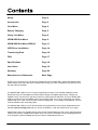
1
Horizon Part Number KM996
Safety
Page 2
Accessories
Page 3
Your Meter
Page 4
Battery Charging
Page 5
Using Your Meter
Page 6
HDSM USB Sub Menu
Page 8
HDSM USB Sub Menu DiSEqC
Page 11
USB Driver Installation
Page 14
Transferring Data
Page 16
FAQ
Page 17
Specifications
Page 18
User Notes
Page 19
Warranty
Page 22
Manufacturer’s Statements
Back Page
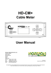
Thank you for choosing to buy the Horizon Global Electronics HDSM USB / USB PLUS satellite meter.
Please read through the instructions carefully before using your meter to familiarise yourself with all of
the new features available.
The HDSM USB / USB PLUS is a compact, lightweight and easy to use satellite installation meter
featuring an easy to read display that shows signal strength and digital signal quality. Finding your
satellite is easy: use the left or right arrow keys to scroll through the selections, and your HDSM USB /
USB PLUS will lock onto the satellite shown in the display when it is in range. Everything you need is
supplied with your meter, which includes a mains charging lead, in-car charger and USB lead. The rain
cover and leather case are already fitted.
The HDSM USB / USB PLUS can also be easily re-programmed from the Horizon Global Electronics
website www.horizonhge.com with your choice of satellites, or with the default file for your region.
Spare battery packs are available directly from Horizon Global Electronics and can be replaced without
voiding your warranty. Replacement leather cases, rain covers, USB leads, mains charging leads and
in-car chargers are also available directly from Horizon Global Electronics Ltd.
Page 1
Safety Instructions
This symbol is intended to alert users of possible hazard or damage in operating this unit.
• Do NOT expose this meter to rain or moisture!
• Clean only with a dry cloth.
• Always use the protective case and cover provided.
• Read the instructions fully before operating your unit for the first time.
• Care should be exercised when using the carry strap as it can present a choking hazard; only use when slipping
or falling is not a possibility.
• Do not disassemble your unit or interfere with the internal components; this will void your warranty and there is a
possibility of electric shock.
“If the equipment is used in a manner not specified by the manufacturer, the protection provided by the
equipment may be impaired”.
• Only use the provided battery, mains lead and DC car charger lead provided, as using other types
may cause damage to your unit, which will void your warranty and may cause electric shock.
Replacement battery packs are available directly from Horizon Global Electronics Ltd.
Should repair or service be required contact us directly at Horizon Global Electronics Ltd by calling us on
+44 (0) 1279 417 005 or via our website www.horizonhge.com
Page 2
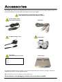
Your HDSM USB / USB PLUS is supplied with this Instruction Manual and these items below. Please check if you
have all the following. If any items are missing please contact your supplier.
Only manufacturer’s replacement parts should be
used, otherwise safety of the meter may be impaired
DC Car Charger Lead
Fitted with 2 Amp Fuse
USB Lead
AC Mains Charger Lead
Battery Pack
Rain Cover
(should be fitted at all times)
Leather Case
The mains lead should match your region. If your mains charger lead is not correct for your region one can be
obtained from Horizon or a local supplier/importer.
Note: The items shown above are subject to change without notice.
Please dispose of the packaging carefully and recycle where possible.
Page 3
Front View
Loop-through connector, L band output only, DC blocked
HDSM
OUTPUT
USB
OFF
MENU
Keypad
ON
INPUT
DIGITAL SATELLITE METER
RF Coax
Connection from
LNB.
128 x 64 dot matrix LCD
(with backlight)
Back View
Battery Cover
NiMH Battery fitted.
Only use Horizon
replacement batteries
Tamper Proof Warranty Label
Side View
Rear View
USB
Input
Side
Front
AC Mains
Charge Input
100-240V ~
0.31A MAX
50/60HZ
DC Charge
Input
12V DC 0.8A
Page 4
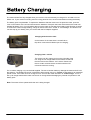
The meter will NOT be fully charged when you receive it. We recommend you charge it for an initial 24 hours
before use. If your meter is not being used for a long period of time, we recommend disconnecting the battery.
The battery pack is replaceable. To replace the batteries: slide the meter out of its protective case, open the
cover on the bottom of the unit and disconnect the batteries. If the pack has been disconnected, the meter will
indicate flat battery (0%). You will still be able to use the meter in this state if the battery pack has been charged.
To restore the correct charge reading, charge as shown below until “Trickle” or “Float Charge” is indicated. You
can also top up your battery from your vehicle with the DC Adapter supplied.
Charging with the mains lead
On the bottom of the case there is a small velcro
flap which covers the AC Mains input for charging.
Charging from a vehicle
The vehicle 12V DC charge port is on the right side of the
unit. Plug the car charger lead into the bottom socket and
the other end to the vehicle’s “aux” socket. Please note
that on certain vehicles the aux socket is switched off
unless the vehicle is running.
For in-vehicle charging only use the lead supplied. The use of another lead may damage the meter and will void
the warranty. The HDSM can remain connected to either power source in “Trickle” charge state for an extended
period of time. If the meter is left on charge for over 24 hours the meter will switch to “Float Charge” - this is a
low cycle charge state and the meter can remain on charge without damaging any internal components or the
battery pack.
Note: The meter will not operate while the unit is being charged.
Page 5
OFF
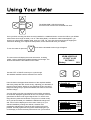
The HDSM USB / USB PLUS keypad.
All of the meter functions are accessed from here.
MENU
ON
Once your dish mounting has been securely installed in a suitable direction connect the LNB to your HDSM
meter with a short length of cable (1.5m or 4 feet being ideal): note that this cable is not supplied – you
should use a high quality satellite cable, such as CT100. Tip: Your dish clamp should be just nipping the
metal work allowing you to adjust the dish position, and it should hold when you release.
To turn the meter on press the
ON
once and the animated Horizon logo will appear.
The next screen will display the meter information, including
model, version, satellite list loaded and battery percentage. The
third line indicates the file loaded into the meter.
HDSM USB PLUS
(C) 2007 V1.0B
UK 706012
Battery
99%
Use the LEFT or RIGHT arrow keys to cycle through
the satellites available until the desired one is shown.
Point the dish in the approximate direction of the required satellite,
and slowly sweep the dish across the sky, adjusting your elevation at
the end of each sweep. Whilst you are sweeping the sky the rate of
beeps will change as you pass each satellite; the scale on the meter
will also change.
H Astra2A Hi
S
Searching
28E
65 dBu
l
H Astra2A Hi
S
q
28E
65 dB lu
100%
You may wish to use the auto-ranging function whilst unlocked to
re-centre the displayed signal level. Do this, for example, if the bar
goes blank but there is still a good signal level. To use the autorange function press the ON button once (twice in Locked mode).
Once you have located your satellite the HDSM will change tone
and “Found” will be displayed on the screen. Peak up on your
selected satellite by making fine azimuth, elevation and
polarisation adjustments to get the S and Q values as high as
possible. Securely tighten the fixing bolts whilst keeping an eye
on the dispay to ensure the best performance from your antenna.
QBER=8.34E-6
Page 6
Continued...
Setup Menu
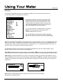
To access the Setup Menu ensure your HDSM USB / USB PLUS is off and press the UP key once.
The following options are available from this menu.
Exit
Backlight on
Clicking on
Brightness
10
Contrast
31
Sleep
6M
English
RF dBuV
BER=x.xxE-x
BER Log
C/N
LNB 13V/18V
Defaults
1.0Ba-0030
By using the keypad as cursor keys you can navigate
through the set up menu using UP and DOWN, and
change values by using LEFT and RIGHT keys. Once
you have made your selections return to the top of the
menu highlighting Exit and press the left or right key to
apply the changes and switch the meter off.
You can also go back to the default setup by selecting
Defaults. This operation will not affect any of the
satellite settings stored in memory.
n.b. The full menu is shown here, whereas only four
options are visible at any one time on the LCD display.
Alternative languages are available for menu items and on-screen information. The RF can be displayed in either
dBuV or Linear modes. The BER numerical display can be changed so that “Found” only is displayed. BER can
be measured in Linear mode for better sensitivity or Logarithmic form. The 1.0Ba-0030 reference may vary; it is
for Horizon use only and does not affect any meter functions.
The HDSM USB / USB PLUS supports many languages, selectable from this menu page: English, French,
Spanish, Italian, German, Dutch, Polish and Scandinavian.
Note: MER measurements can also be made by changing C/N to MER in the setup menu. Results will be logged
as C/N (Carrier-to-Noise ratio) or MER (modulation error ratio) according to this setting (HDSM USB PLUS only).
LNB Voltage: This feature enables you to switch the LNB supply voltage off. Whist the LNB Voltage is set to 0
Volts the Satellite name on the top line of the display will alternate with “LNB 0V” to indicate that no LNB voltage
is applied. This selection will remain active until it has been changed back to LNB 13V/18V even if the meter is
switched off.
H Astra2A Hi
S
Searching
28E
65 dBu
l
LNB 0V
65 dBu
l
S
Searching
Note: While the LNB Voltage has been selected as 0V then the top line of the display
will alternate as illustrated above.
Page 7
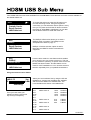
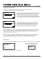
Your HDSM USB has new extras available from the sub menu. These features and more are also available on
the HDSM USB PLUS.
◄Exit
►
DiSEqC
Custom Carrier
Recall Custom
LNB/Cable test
To access the sub menu press the UP button once
from the searching screen. Using the keypad as
cursor keys you can select the various options. At any
time you can press and hold the UP button to switch
the meter off. When Exit is highlighted, you can also
use the RIGHT button to switch the meter off.
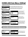
The DiSEqC LNB function allows you to send a
DiSEqC switch command. The DiSEqC menus
are explained in detail on page 11.
Exit
►DiSEqC
Custom Carrier
Recall Custom
LNB/Cable test
DiSEqC 4 Position switches, Option A and B,
Dual Horn and SMATV Switch commands are
supported.
Exit
DiSEqC
Custom carrier mode is a new feature which enables
you to specify your own carrier to lock on to. This can
be very useful for optimising a specific service once the
satellite has been located - and this feature can be
used for VSAT installation too. You can also store this
selection separately from your predefined selections.
►Custom Carrier
Recall Custom
LNB/Cable test
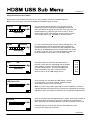
Using the Custom Carrier feature
LNB 9.75
S
Searching
▼▲
0 dBu
l
Once you have made your
selection press the right arrow
key to set your frequency.
Select your local oscillator first by using the UP and
DOWN keys. Various local oscillators are available
and some have 22KHz tone available also. The
Local Oscillators are shown in the table below.
9.75
10.6
10.0
10.25
10.5
10.7
10.7
10.75
10.75
11.25
11.25
11.3
11.3
22KHz tone on
22KHz tone on
22KHz tone on
17.25
18.25
18.75
19.25
19.75
Ka-Band
Ka-Band
Ka-Band
Ka-Band
Ka-Band
5.15
5.76
5.95
C-Band
C-Band
C-Band
22KHz tone on
22KHz tone on
Continued...
Page 8
Continued...
Using the Custom Carrier feature
Now that the local oscillator has been set you can proceed to select your desired frequency.
Note: The local oscillator selected will dictate the available frequency range.
Carrier
1 0700MHz
0 dBu
l
S
Searching
Symb
2 7500kBd
0 dBu
l
S
Searching
FEC
3/4
0 dBu
l
S
Searching
LNB Horiz 18V
0 dBu
l
S
Searching
0 dBu
l
Searching
In much the same manner that you defined the frequency, set
the Symbol Rate to match the wanted signal: highlight the
numbers with the LEFT or RIGHT key and change the value
with the UP and DOWN arrow keys. Symbol rates from 01000
to 45000 can be set. Once you have the desired symbol rate
press the RIGHT arrow to step on to the FEC screen.
From this screen we can select the desired FEC. If
the FEC is unknown then select Any and the HDSM
USB / USB PLUS will try them all when searching
from the Custom Carrier. The FEC’s available are
show in the table to the right. Press the RIGHT
arrow to step on to the LNB voltage screen.
1/2
2/3
3/4
5/6
7/8
Any
On this screen we can select the LNB voltage: 18 Volts
for Horizontal or 13 Volts for Vertical. Press the RIGHT
arrow button to step on to the IQ screen.
Note: If you are using a block type LNB for VSAT installation, 18 Volts is
typically selected to power this kind of LNB, as the polarisation is manually
adjusted. Consult your LNB documentation for its operational requirements.
IQ Norm
S
You can set the desired frequency by using the UP and
DOWN arrow keys to change the highlighted number and
LEFT and RIGHT to step to the next one. Once you have your
desired frequency, press the right arrow to step on to the
Symbol Rate screen. Note that you will not be able to select
out-of-range values (e.g. 20700MHz in Ku band mode).
Here we can select IQ unswapped (Norm) or Swap. Sometimes IQ Swap is
required to obtain a lock but for most of the time this is left selected to
Norm (Normal). use the Swap selection if you failed to obtain a lock so far.
Press the right arrow key to step onto the Save and Exit screen
once you have made your selection.
Continued...
Page 9
Continued...
Using the Custom Carrier feature
Now that all of your parameters have been set, you have the option to save your custom
carrier to memory that’s separate from the predefined selections.
Save and Exit
▼
0 dBu
l
S
Searching
Discard
▼
0 dBu
l
S
Searching
Pressing the DOWN arrow on this screen will save your custom carrier to
memory and exit to searching mode, where you can now use your
custom carrier settings to find the desired service. If you prefer not to
save your settings press the RIGHT arrow to step on to the Discard
screen. If you wish to use your custom carrier at a later installation, this
can be recalled by using the Recall Custom option from the sub menu.
By pressing the DOWN arrow on this screen all of the values you
have set will be discarded and the meter will return to searching
mode on the last satellite selected before entering Custom Carrier
mode. Alternatively, use the RIGHT button to cycle through the
custom carrier options to set another carrier of your choice.
Note: The HDSM USB / USB PLUS is only compatible with DVB QPSK modulated carriers and will not show
a lock on other types of modulation such as DigiCipher, DVB-S2 8PSK or turbo encoded services. When using
lower symbol rates (less than 04000) it may take a few seconds to obtain a lock, and it will require much
slower motion when pointing your antenna.
Tip: Common carrier configurations can result in a multiple lock situation. For example, carriers that have an
FEC of 3 / 4 and a Symbol Rate of 27500 will probably lock on multiple satellites. Where possible, look for
unique Symbol Rates that are unlikely to be duplicated on other satellites at the defined frequency.
LNB / Cable Test
The LNB / Cable test is a quick function to check for possible fault conditions and will indicate if there is a problem.
LNB / Cable test
Please wait...
◄Exit
The test results will appear after a few
seconds as indicated in the table below.
LNB / Cable OK
LNB Fault
LNB / Cable Fault
Note: The above function is for indicative purposes only.
Page 10
The DiSEqC Switch functions are available from the sub menu of the HDSM USB and USB Plus.
Exit
►DiSEqC
Custom Carrier
Recall Custom
LNB/Cable test
Exit
►4 Pos Switch
Options
Dual Horn
SMATV switch
Exit
4 Pos Switch
►Options
From the sub menu DiSEqC function shown here you can
select a variety of DiSEqC switch commands to suit the needs
of your installation. Press the right arrow button to access the
the different options available. Once a DiSEqC command has
been selected with the right arrow key the command will be
sent and you will be returned to the last satellite selected.
The 4 Position Switch option
gives you the selections of
A,B,C and D and these
selections can be used with a
conventional 4 way DiSEqC
switch. Selecting Exit here will
take you back to the sub menu.
◄Exit
LNB A
LNB B
LNB C
LNB D
◄Exit
The Options selection
enables you to send Tone
Burst commands (A or B).
Selecting Exit here will take
you back to the sub menu.
Option A
Option B
Dual Horn
SMATV switch
Exit
4 Pos Switch
Options
►Dual Horn
SMATV switch
The Dual Horn option is for use
with dual feed LNB assemblies
enabling you to select the band
and polarisation available
individually. Selecting Exit here
will take you back to the sub
menu.
◄Exit
SAT A_Ver_Low
SAT A_Ver_High
SAT A_Hor_Low
▼For more
The following selections are available from the Dual Horn menu.
Satellite A Vertical Low
Satellite A Vertical High
Satellite A Horizontal Low
Satellite A Horizontal High
Satellite B Vertical Low
Satellite B Vertical High
Satellite B Horizontal Low
Satellite B Horizontal High
For SMATV switch systems the following DiSEqC command options are available.
Exit
4 Pos Switch
Options
Dual Horn
►SMATV Switch
Page 11
◄Exit
SMATV switch
SMATV switch
SMATV switch
▼For more
1
2
3
The SMATV switch option is for
use with systems with up to 16
inputs. Selecting Exit here will
take you back to the sub menu.
Note: The following additional features are only available on the Sub Menu for HDSM USB PLUS.
Spectrum mode
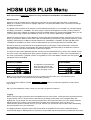
Spectrum mode is available from the Sub-menu (press the UP arrow while the signal level or carrier/noise
display is on screen). Scroll down to highlight “Spectrum”, and press the RIGHT arrow. The screen will change
to display the spectrum.
The graphic will be centred on the frequency of the selected transponder: in our example of a Low Band setting,
the display is centred on 10728MHz. The span (range of frequencies displayed on screen) is set by default to
240MHz; which gives a display of 8 adjacent carriers at 30MHz spacing. By pressing the DOWN button, you can
cycle through a range of spans from 60MHz (to zoom in on one carrier in particular) to 1200MHz.
Centre the chosen frequency on the display by pressing the LEFT and RIGHT buttons. Note that you will not be
able to go beyond the limits for each band, which are indicated by arrows pointing right (lowest frequency) or left
(highest). Note that the Low Band coverage extends from 10700MHz to 11600Mhz, and the High Band from
11550MHz to 12750MHz, so there is some overlap between the Low and High Band for Universal LNB’s.
RF level is shown by a solid band at each sampled frequency (see image). There will be areas of low-level
signal between the carriers, and the bigger the distance between peaks and valleys, the better the carrier-tonoise ratio. Good C/N ratio is important for trouble-free reception!
The top line of the screen alternates between “Centre” plus the selected frequency (shown at the dotted vertical
line in the centre of the display) and “Span” plus the frequency span in MHz. In “Span” view, the polarisation of
the carrier (H)orizontal or (V)ertical is shown. If High Band is in use, and 22KHz is enabled, the tone symbol
will appear next to the Polarity.
Centre 10728MHz
►
►
►
►
Span 240MHz
The Spectrum information bar
at the top of this screen will
alternate between the current
frequency and span in use
V
►
►
►
►
Note: You can exit spectrum mode at any time by pressing the UP button once. This will return you to
the searching screen on the selection that you made previously.
In low signal level conditions use the
may be seen.
► Spectrum
option to increase the amplitude so that carriers
Tip: If you have defined a custom carrier you can view it in spectrum mode too.
Logging
Before using the logging function acquire the satellite that you have chosen, ensuring that the received levels are
as good as they can be. Then access the Sub-menu by pressing the UP button once; navigate down and
highlight the “Log as 00000" line. By pressing the right arrow at this point the levels from your satellite selection
will be stored in to the memory and numbered; this number will increment each time your store your
measurements. Note this number down on your job sheet as you will need to refer to it later when downloading
the log information from your meter later.
The logging software required to extract the stored values is available from the Horizon Global Electronics
download web page for HDSM products. Instructions are provided with the software as a printable PDF document.
Page 12
Continued...
Note: The following additional features are only available on the Sub Menu for HDSM USB PLUS.
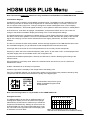
Constellation diagram
Provided the meter is locked to a DVB QPSK modulated carrier, Constellation mode is available from the
Sub-menu (press the UP button while the signal level or carrier/noise display is on screen). If there is no
lock, the option will be “greyed out”. This type of diagram is almost meaningless when it cannot display
formatted QPSK data – dots would appear randomly in each quadrant, and there would be no visible pattern.
In the Sub-menu, scroll down to highlight “Constellation”, and press the RIGHT arrow. The screen will
change to the QPSK constellation display and a listing of the current transponder settings.
The graphic displays the 4 quadrants of a QPSK signal. A “good” display will show a cluster of dots towards
the outer corner of each quadrant. The more concentrated the cluster, the better the quality of the received
signal; dots “straying” from the cluster indicate noise on the signal, phase errors, and other unwanted
artefacts.
The aim is to achieve the best result possible, which a thorough alignment of the LNB should achieve. With
the constellation diagram, you get reassurance that the adjustments have been done well.
At the right side of the screen is a list of the parameters for the currently chosen transponder:
Frequency in MHz: this is the measured frequency after “pull-in” by the meter’s AFC, so the displayed value
may differ slightly from the nominated value in the configuration file;
Symbol Rate in kiloBaud (kiloSamples / Second): the data rate is critical in identifying and locking to the
selected carrier;
FEC (forward error correction) value: data on the selected carrier will conform to one of a short list of
standard FEC values;
IQ Norm indicates that no IQ Swap is not present.
At bottom right, there is a display of the charge state of the battery pack.
Tip: The constellation diagram can be used down stream from the LNB to trace problems caused by faulty
components that introduce noise and affect the quality of the digital signal.
10713MHz
22000kBd
FEC 5/6
IQ Norm
This illustration shows how a typical
QPSK constellation diagram would
be represented.
Note: The following feature is only available on the HDSM USB PLUS.
Histogram function
The HDSM USB PLUS also has an additional feature of
a histographic display; this can be used in SCR (Single
Cable Router) environments to measure up to 9 different
frequencies simultaneously. Settings for this function can
be downloaded from the Horizon Global Electronics web
site. The scale on the right hand side of the display gives
an indication of level in dBuV.
Page 13
1 2 3 4 5 6 7 8 9
80
70
60
Note: The histographic function can only be
selected when downloaded as an additional setting.
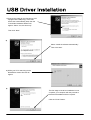
1) Connect the meter for the first time to a PC
equipped with USB port(s), If the USB
drivers don’t automatically load, then the
“Found New Hardware Wizard” will
appear. Select “Yes, this time only”.
Then click “Next”
2)
Select “Install the software automatically”
Then click “Next”
3) While your PC is searching for the
DRIVERS a window like this will
appear
4)
The first stage of the driver installation is now
complete; your computer will now proceed to
download the additional driver required.
Click the “Finish” Button.
Page 14
Continued...
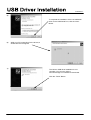
5)
To complete the installation of the new additional
driver for the USB Serial Port, click the “Next”
Button.
6)
While your PC is searching for the drivers, a
window like this will appear.
7)
The Horizon USB driver installation is now
complete. You can now visit the
www.horizonhge.com website for downloads.
Click the “Finish” Button.
Page 15
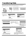
Now that your USB drivers are installed, you can download selections from the Horizon Global Electronics
Download website for HDSM - for updates or to create your preferred list. Go to www.horizonhge.com
Please follow the steps illustrated below to upload new selections to your meter.
1)
Wait for the HSDM USB / USB
PLUS to display “Program
Mode” (while establishing
communication the display
may flash and the sounder
may beep. This is normal).
Program Mode
2) Ensure that USB is
ticked on the ComPort
drop-down menu as
shown.
After a few seconds a progress bar
will appear
Then click Transfer
When complete you will see a popup
window that says “ Transfer
Complete!”. Click “OK” and close the
program.
3)
Disconnect the meter from the computer, power it up and it will be ready for use.
Trouble shooting file transfer problems.
If you receive a Serial Interface error
check your COM-port selection, and
select the correct COM port. (USB)
If you get this error message “Error – Ack Not
Received”. Check that the USB interface
connection is correctly made and that the USB
cable is undamaged.
Page 16
Ack Not Received Error
1) Incorrect Com Port selected. Check to make sure USB Com Port is selected.
2) Battery low.
USB Port Error
1) Drivers not found (drivers available from website).
2) Check that the USB Lead is connected correctly.
3) USB Lead may become damaged or a poor connection may cause communication errors.
4) USB Port Damaged.
I2C Error Indication
An I2C error indicates that the internal electronics are not receiving correct communication with the internal tuner.
Generally caused by:
1) Low battery power (if the meter has been left In a cold environment, this will reduce the battery life).
2) Connecting the LNB “hot” (i.e. while the meter is switched on) can cause a surge which will result in an I2C
error. You should always connect the LNB with the meter switched off.
Meter Shutting Down
1) Low Battery Charge.
2) Sleep timer – check timer setting in the Setup menu.
3) LNB short circuit or drawing excessive current.
Meter does not show a lock.
Make sure you have a current download of files in your meter; if it's been a while since you have downloaded you
should do so again.
Also try toggling between BER Linear & BER Log (with meter off, hold UP button down until setup display
appears, scroll down to the bottom & you will see BER on left side; press the RIGHT arrow & the right side will
change between linear & log. Also confirm in the setup display that you have the meter set to display 'FOUND')
Apple Mac
The software is not MAC compatible.
Storage
If you wish to store your unit for extended periods of time greater than 3 weeks disconnect the battery connectors.
When required reconnect and charge overnight prior to use.
Tip: To keep your battery in good working order we recommend a full overnight charge at least once every two
weeks for light usage. For every day usage we recommend to put your unit on overnight charge prior to the next
working day to ensure maximum battery power is available.
Page 17
Charging
Universal Mains Battery Charger 100V~240V ~ 0.31A MAX 50/60Hz. Intelligent charger (CE approved)
with delta V delta T detection, Fast Charge then Trickle.
DC 12V Charger 0.8 Amps (1.3 Amps peak).
Figure 8 mains input connector.
2.1mm female plug for external charge via 12 Volt DC 2 Amp fused car charger.
Run time with full charge, average 5 hours from 3.3Ah NiMH battery
Connections
LNB input via `F` type female connector. Impedance 75 ohms with short circuit protection 0.5 Amps automatic limiter
Computer Interface: USB port for updating satellite settings
Operating Specifications
RF input range 950-2150MHz - 65dBm to 25 dBm
LNB Supply Voltage: 13V for V and 18V for H @ 250 mA nominal
LNB Short circuit protection @ 500mA
64 Transponders or 32 Satellites, horizontal & vertical
DVB, C & KU band, QPSK, VSAT compatible
Input dynamic range – 65dBm~25dBm
RF Level can be displayed in dBuV (general accuracy +/-1dB) or linear scale (256 steps). Feature available
in setup mode.
Input impedance 75 Ohms
Symbol Frequency rate from 1Msps~45Msps
C/N (carrier to noise) is displayed in dB
Signal Strength and BER displayed together
The Quality indicator (pre BER or bit error rate) locks on faster making it easier to identify the satellite
initially; typically locks in less than 100mS
Instead of “Found” to indicate the lock on correct satellites, the actual BER can be displayed. This Feature
is available in set up mode.
Audible and visual tune-in, with selectable and adjustable display backlight and contrast.
Spares for your meter
Description
Part Numbers
Rain Cover
ARSUSB
Car Charge Lead
AW992CIG
2 Amp Fuse(F)
CF2AGQB
Battery Pack Ni-MH 7.2V 3.3Ah
BP7233/2
USB Lead
AW998 USB
Leather Case
AL001BK
Page 18
Page 19
Page 20
Page 21
Thanks for taking the time to fill out your warranty card. Horizon will, at our option, repair or replace any
HORIZON digital satellite meter found to be defective in manufacture within the warranty period (1 year).
The warranty period is determined by the date of the HDSM purchase. Keep your receipt as proof of purchase.
Otherwise the warranty is determined by date of manufacture.
This warranty does not apply to damage caused by accident, misuse, or tampering with the unit or seals. This
does not affect your statutory rights.
The warranty card is available for download from website.
-----------------------------------------------------------------------------------------------------------------------Warranty Card
Product:
Serial Number:
Date Of Purchase:
Buyer’s Name:
Company:
Phone No:
Email Address:
Address:
Fault Description:
Horizon Global Electronics Ltd
Unit 3 West Side
Flex Meadow
Harlow
Essex
United Kingdom
Phone:
Fax:
Email:
Web:
+44 (0) 1279 417005
+44 (0) 1279 417025
[email protected]
www.horizonhge.com
Page 22
LIMITED WARRANTY
Horizon will, at our option, repair or replace any HORIZON Digital Satellite Meter found to be defective
in manufacture within the warranty period (1 year).
The warranty period is determined by the date of HDSM purchase. Keep your receipt as proof of
purchase. Otherwise the warranty is determined by date of manufacture.
This warranty does not apply to damage caused by accident, misuse, or tampering with the unit or
seals. This does not affect your statutory rights.
DECLARATION OF CONFORMITY
Manufacturer: Horizon Global Electronics Ltd
Address: Unit 3, West Side, Flex Meadow, Harlow, Essex, CM19 5TJ
Declares that the Horizon Digital Satellite Meter (HDSM USB / USB PLUS) complies with the following
directives and standards.
Safety EN610 10-1:2001
EMC 61326:1997
All Horizon products are ROHS compliant.
Technical Department
Horizon Global Electronics
July 2007
CONTACT DETAILS
Horizon Global Electronics Ltd.
Unit 3
West Side
Flex Meadow
Harlow
Essex
CM19 5TJ
Tel:
Fax:
Email:
Web:
+44 (0)1279 471 005
+44 (0)1279 417 025
[email protected]
www.horizonhge.com
Producer ID for the purposes of WEEE regulations: WEE/BB0191UV