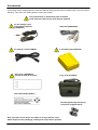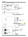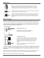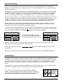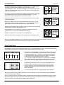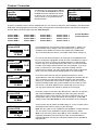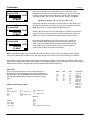
1
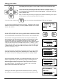
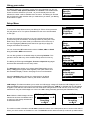
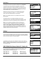
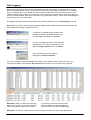
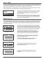
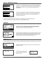
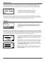
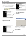
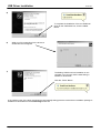
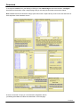
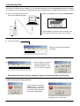
OUT
30V LNB
output
OFF
ON
INPUT
BPSK – QPSK – 8PSK – Turbo Code
Perfect 10 Satellite Distributing
1-800-205-8620
3901 Progress Street
North Little Rock, Arkansas 72114
Publication: KM111 V1.3
© Copyright, 2010, Perfect 10 Satellite Distributing. No part of this document may be copied or reproduced without the written consent of
Perfect 10 Satellite Distributing, 3901 Progress Street, North Little Rock, Arkansas.
Contents
Contents / Disclaimer
Safety / Satellite Lists
Accessories
Your Meter
Maintenance / Battery Charging
Using Your Meter
Setup Menu
Sub Menu / DiSEqC / SW21/SW44
Spectrum Display / Constellation
Five Point Scan
Custom / Customize
Data Logging
DirecTv SWiM / SWiM Output Test
DirectTv SWiM Dual Display
LNB Drift / LNB/Cable Test
WildBluetm
Orientation
USB Driver Installation
Download
Transferring Data
FAQ
Specifications / Battery change
User Notes
Manufacturer’s Statements
Page 1
Page 2
Page 3
Page 4
Page 5
Page 6
Page 7
Page 8
Page 9
Page 10
Page 11
Page 13
Page 14
Page 15
Page 15
Page 16
Page 17
Page 18
Page 20
Page 22
Page 23
Page 24
Page 25
Rear cover
Thank you for choosing to buy the BirDog ULTRA satellite meter. Please read through the instructions
carefully before using your meter to familiarize yourself with all of the new features available.
The BirDog ULTRA is a compact, lightweight and easy to use satellite installation meter featuring an easy to
read display that shows signal strength and digital signal quality. Finding your satellite is easy: use the left or
right arrow keys to scroll through the selections, and your BirDog Ultra will lock onto the satellite shown in the
display when it is in range. Everything you need is supplied with your meter, which includes a A/C charger
cord, in-car charger and USB lead. The rain cover and carry case are already fitted.
The BirDog ULTRA can also be easily re-programmed from the BirDog website www.birdog.tv
(via a link to the BirDog ULTRA downloads) with your choice of satellites, or with the current default file.
Spare Li-Po (Lithium-Polymer) battery packs are available directly from Perfect-10 or authorized dealers, and
can be replaced without voiding your warranty. Replacement carry cases, rain covers, USB leads, A/C
charging leads and in-car chargers are also available directly from Perfect-10 or authorized dealers.
Disclaimer
The satellite operators have complete control of the data stream information. They change the data stream
methods and technology at will and for their own purposes. Perfect-10 has no control over the evolution of
data streaming. While we will make every effort to provide you with current satellite identification downloads,
this device could eventually lose its ability to identify specific satellites by the evolution of technology.
Page 1
Safety
This symbol is intended to alert users of possible hazard or damage in operating this unit.
• WARNING! This device is capable of generating 30 Volts. Always connect the LNBF to the INPUT only.
• Do NOT expose this meter to rain or moisture!
• Clean only with a dry cloth.
• Always use the protective case and cover provided.
• Read the instructions carefully before operating your unit for the first time.
• Care should be exercized when using the carry strap as it can present a
choking hazard; only use when slipping or falling is not a possibility.
• Do not disassemble your unit or interfere with the internal components;
this will void your warranty and there is a possibility of electric shock.
“If the equipment is used in a manner not specified by the manufacturer, the protection provided by the
equipment may be impaired”.
• Only use the provided battery, AC charger cord and DC car charger lead provided, as using
other types may cause damage to your unit, which will void your warranty and may cause electric
shock. Replacement battery packs are available directly from Perfect-10 or an authorized dealer.
Li-Po battery notes:
A damaged battery represents a hazard and should be replaced. Always replace
damaged battery packs with the correct type – never attempt to repair them.
Remember:
Do not short-circuit the battery terminals
Do not dispose of in fire
Do not disassemble
Satellite lists
You can change the pre-loaded satellite list which is currently in the memory of the BirDog ULTRA by going to the
www.birdog.tv web site. The instruction set which follows in this manual, “Download”, was current at the time of
the manual’s printing but is superceded by any revisions found on the web site.
Note that the BirDog ULTRA may not be able to positively identify the correct locations of satellites and in some
instances cross identification can occur. Some of the satellites available for download from the BirDog website do
cause the BirDog to indicate “Found” in one or more locations. You may download any of these other satellites
but they are to be used with the understanding that misidentification may result. A thorough knowledge of the
magnetic heading to the satellite you are attempting to positively identify can help you resolve some of the
duplicate satellite locations.
The default satellite lists which are pre-loaded at the factory will be overwritten by any uploads that you perform.
However, the factory default list is also available from the web site and can be re-loaded if desired. Note that the
satellites you choose need to be selected in the sequence that you want them to appear in the BirDog ULTRA. If
for example, you select a satellite located at 119˚ and then select one at 101˚, the 119˚ satellite will come up first
as you scroll through the list of satellites in the stored memory. This can be handy knowledge as you may prefer
to have the satellites you use most, located at the first in the list.
You can load from one to four lists each with up to 255 selections to the BirDog ULTRA memory. The fewer lines
you select for your custom list, the quicker you can find the one you want when lining up antennas. Up to four lists
can be retained in the BirDog Plus memory. The previous list file is overwritten by the next upload you do.
We HIGHLY suggest that if more than one polarity is indicated on the web site for a particular satellite file, that
you load both polarities in your BirDog ULTRA. See Page 19 “Download” for an example.
Page 2
Accessories
Your BirDog Ultra is supplied with this Instruction Manual and these items below. Please check if you have all the
following. If any items are missing please contact your supplier.
Only manufacturer’s replacement parts should be
used, otherwise safety of the meter may be impaired
DC Car Charger Lead
Fitted with 2 Amp Fuse
(LDSM12DC)
USB Lead (AW998USB)
AC Charger Lead (LDSM020)
Li-Po Battery Pack (BP1524)
Rain Cover (ARHDBDU)
(should be fitted at all times)
Carry case (AL006BK)
Quick Start Guide (KM971)
Interchangeable High Frequency
connectors (supplied fitted)
Note: The items shown above are subject to change without notice.
Please dispose of the packaging carefully and recycle where possible.
Page 3
Your Meter
30V DC supply for WildBlue
Keypad
LNB Input
Tamper proof
warranty seal
Serial number
Battery cover
Only use BirDog ULTRA Li-Po
(Lithium Polymer) replacement
battery packs (fitted).
USB
Input
1.5A
AC Charge Input
100 – 240 V ~
0.8A Max
50/60 Hz
DC Charge
Input 12V DC
1.5A
Page 4
Maintenance
Note: Your new BirDog Ultra features replaceable high frequency connectors.
Periodically these may require replacement and inspection to insure continued
reliable operation. For the removal of connectors use a 7/16th or 11mm spanner.
Carefully clean the surrounding area with a dry lint free cloth to prevent debris falling
into the high frequency connector socket well.
Tip: Check for any copper fragments that may have gathered in the well of the high
frequency connector socket on the meter. These can be removed with a dry Q-tip.
When re-fitting F barrels only tighten enough to prevent the barrel being removed
by hand.
Battery charging
The meter will NOT be fully charged when you receive it. We recommend you charge it for an initial 8 hours
before use. If your meter is not being used for a long period of time, we recommend disconnecting the battery.
You can also top off your battery from your vehicle with the in car DC Adapter supplied. You should top up the
charge every 2 weeks. The battery pack is replaceable, but it should only be removed or disconnected in the
event of a failure. Please see page 23 for battery removal.
Charging with the AC cord
On the bottom of the case there is a small velcro
flap which covers the AC input for charging.
Charging from a vehicle
1.5A
The vehicle 12V DC charge port is on the right side of the unit.
Plug the car charger lead into the bottom socket and the other
end to the vehicle’s “aux” socket. Please note that on certain
vehicles the aux socket is switched off unless the vehicle is
running.
Note: Do not charge from a vehicle with a higher battery
voltage or positive ground!
For in-vehicle charging only use the lead supplied. The use of another lead may damage the meter and will void
the warranty. The BirDog ULTRA can remain connected to either power source in “Trickle” charge state for an
extended period of time. Once “Charge Complete” appears on the display the BirDog Ultra will be in a trickle
charge state.
Note: When charging your battery BirDog Li-Po battery please ensure that the ambient temperature is above
freezing point 32º F (0º C) and not above 100º F (40º C) this will prevent damage to your battery pack.
Note: The meter will not operate while the unit is being charged.
Page 5
Using your meter
The BirDog ULTRA keypad. All of the meter functions are accessed from here.
OFF
ON
Once your dish mounting has been securely installed in a suitable direction
connect the LNB to your BirDog ULTRA meter with a short length of cable (1.5m
or 4 feet being ideal): note that this cable is not supplied – you should use a high
quality satellite cable.
Tip: Your dish clamp should be just nipping the metal work allowing you to adjust
the dish position, and it should hold when you release.
To turn the meter on press the
button once and the animated BirDog ULTRA logo will appear.
The next screen will display the meter information, including model, version,
satellite list selected and battery percentage. Note: Satellites shown will be
from the last used list.
BIRDOG ULTRA
(c) 2010 V2. 102U
DirecTv / WB
Battery
99%
Use the LEFT or RIGHT arrow keys to cycle through the satellites available
until the desired one is shown. You may need to use the sub menu to access
your required satellite as the BirDog ULTRA can store up to 4 satellite lists.
Point the dish in the approximate direction of the required satellite, and
slowly sweep the dish across the sky, adjusting your elevation at the end
of each sweep. While you are sweeping the sky the rate of beeps will
change as you pass each satellite; the scale on the meter will also change.
If very low RF levels are found the dBu value will show << dBu (e.g. lowoutput LNB, long cable run or no visible carrier). For extremely high levels
>> dBu will show (e.g. high-output LNB, very strong carrier or a high-gain
distribution amplifier in circuit).
DTV Ka/Ku&3G
S
65 dB
Searching
65 d
dbuV
BuV
I
DTV Ka/Ku&3G
Once a lock has been acquired the second bar will show you the signal to
noise ratio, referenced in either M for Modulation Error Ratio (MER) or C
(for carrier-to-noise). This reading is directly relative to quality of signal.
101
101
S
73 dB
M
11.3 dB
dbuV
BuV
Found 65 d
I
Once a lock has been acquired, if you press the ON button once you can
make fine adjustments to your antenna by using the linear signal level
display and quality indicator (shown as L & Q). If the L and Q values
exceed the graph at either end, press the ON button twice to re-center
the bar graph display. This display shows “Carrier” and a magnifying
glass symbol on the bottom line when in use.
DTV Ka/Ku&3G
S
182
M
136
Carrier
DTV Ka/Ku&3G
Pressing the ON button again will show the IRD level screen, pressing
the ON button once more will return you to the initial measurement mode.
101
101
IRD Level
I
71
dbuV
Found 65 d
BuV
I
Continued...
Page 6
Using your meter
Continued...
The BirDog Ultra has 4 operating modes which are selectable from the sub
menu: DirecTv / WB, Specific, Standard, and Custom. This enables faster
access to the the selections you need - as you will already have one list
selected, the other 3 will be available from the menu. The BirDog ULTRA will
also remember the last selection that you made when you switch your BirDog
off and back on again.
Constellation
Specific
Standard
►Custom
▲▼For more
Setup Menu
To access the Setup Menu ensure your BirDog ULTRA is off and press the
UP (Off) button once. The options available from this menu are illustrated
on the right.
By using the keypad as cursor keys you can navigate through the set
up menu using UP and DOWN, and change values by using LEFT and
RIGHT keys. Once you have made your selections return to the top of
the menu highlighting Exit and press the left or right key to apply the
changes and switch the meter off.
You can choose the RF measurement values of dBuV, dBm or dBmV
along with C/N or MER measurement.
You can also go back to the default setup by selecting Defaults. This
operation will not affect any of the satellite settings stored in memory.
The BirDog ULTRA supports English, French and Spanish languages
and these are selectable from the setup menu.
The Azimuth option allows you to select either True (relative to true
North) or Mag (with magnetic offset applied). This option affects how
the Orientation display is shown. See page 16 for more information.
Using the Defaults option will set your meter back to its default
settings; the satellites stored in memory will remain unaffected.
Exit
Backlight on
Clicking on
Brightness
10
Push ◄ ► to exit
Contrast
Sleep
English
RF dBuV
I
Use ◄ ► to
20
6M
alter
LNB 13V/18V
Defaults
Azimuth Mag
2. 1Ua-0002
Use ◄ ► to
alter
Defaults
Azimuth mag
2. 1Ua-0002
DPD V1. 4c
▲For more
LNB Voltage: This feature enables you to switch the LNB supply voltage off. While the LNB Voltage is set to 0
Volts the Satellite name on the top line of the display will alternate with “LNB 0V” to indicate that no LNB voltage
is applied. This selection will remain active until it has been changed back to LNB 13V/18V, even if the meter is
switched off. Only set LNB Voltage to 0 Volts if the LNB is being externally powered (see LNB/Cable Test).
Note: While the LNB Voltage has been
selected as 0V then the satellite name
on top line of the display will alternate
as illustrated above.
KV Galaxy-3C
S
95
<< dB
Searching
<< d
dbuV
BuV
I
LNB 0V
S
<< dB
Searching
<< d
dbuV
BuV
I
The version number information 2. 1Ua-0002 towards the bottom of the Setup Menu has no function other than to
inform you which version of firmware is in use. The DPD V1. 4c line references the Zip code look up table loaded.
Page 7
Sub Menu
Your BirDog ULTRA has many features available from the Sub Menu.
To access the sub menu press the UP (off) button once from the
searching or found screen. Using the keypad as cursor keys you can
select the various options. At any time you can press and hold the UP
button to switch the meter off. When Exit is highlighted, you can also
use the RIGHT button to switch the meter off.
Selections for DirecTv are found in in the standard list and these
include the Dual Display for SWM 101 / 119 and the Histogram
Pass / Fail function described later in this document.
Note: The constellation feature is only available when a lock has
been acquired.
The log all function is a new feature that allows you to log the
measurement values of the satellite transponders belonging the major
boradcasters such as DirecTv DishNetwork, Bell and ShawDirect, etc
Note: If you are operating the BirDog ULTRA with Standard List
selected, then Specific, Standard and Custom lists are available. If
DirecTv / WB has been selected, then Standard, StarChoice and
Custom List are available. If the Speficifc has been selected, then
DirecTv / WB, Standard and Custom List are available. If Custom list
has been selected, then DirecTv / WB, Specific and Standard lists are
available, along with the Customize function.
◄Exit
DiSEqC
SW21/SW44
Spectrum
▼For more
►
Spectrum
Constellation
Specific
►Standard
▲▼For more
Custom
Customize
LNB 21V
►Orientation
▲▼For More
Log as
00000
Log All
LNB Drift
►LNB/Cable test
▲For more
DiSEqC
From the sub menu DiSEqC function shown here you can select a DiSEqC
switch command to suit the needs of your installation. Press the right arrow
button to access the switch commands available.
Exit
►DiSEqC
SW21/SW44
Spectrum
▼For more
The DiSEqC function gives you the selections of A,B,C and D. Selecting
Exit here will take you back to the sub menu. Use the Up and Down arrow
buttons to highlight the desired DiSEqC command and press the right
arrow button to send.
◄Exit
LNB A
LNB B
LNB C
LNB D
SW21/SW44 (Dish Network Switch 21 / Switch 44)
The very latest version of BirDog firmware also includes Switch 21 and
Switch 44 functions that enable you to send the correct pulse data to
operate Switch 21 and Switch 44 devices.
SW21 DISH 1 RH
SW21 DISH 1 LH
SW21 DISH 2 RH
SW21 DISH 2 LH
SW44 DISH 1 A
SW44 DISH 1 B
SW44 DISH 2 A
SW44 DISH 2 B
Note: RH and LH
refer to polarisation
(Right Hand Circular
Left Hand Circular).
◄Exit
SW21 DISH 1 RH
SW21 DISH 1 LH
SW21 DISH 2 RH
▼For more
Page 8
Spectrum Display
Spectrum mode is available from the Sub-menu (press the UP arrow while the signal level or carrier/noise
display is on screen). Scroll down to highlight “Spectrum”, and press the RIGHT arrow. The screen will change
to display the spectrum.
The graphic will be centred on the frequency of the selected transponder: in our example of a Low Band setting,
the display is centred on 11840MHz. The span (range of frequencies displayed on screen) is set by default to
240MHz; which gives a display of up to 8 adjacent carriers at 30MHz spacing. By pressing the DOWN button,
you can cycle through a range of spans from 120MHz (to zoom in on the carriers in one area) to 1200MHz.
Centre the chosen frequency on the display by pressing the LEFT and RIGHT buttons. Note that you will not be
able to go beyond the limits for each band, which are indicated by arrows pointing right (lowest frequency) or left
(highest). Note that the Low Band coverage extends from 10700MHz to 11600Mhz, and the High Band from
11550MHz to 12750MHz, so there is some overlap between the Low and High Band for Universal LNB’s.
RF level is shown by a solid band at each sampled frequency (see image). There will be areas of low-level
signal between the carriers, and the bigger the distance between peaks and valleys, the better the carrier-tonoise ratio. Good C/N ratio is important for trouble-free reception!
The top line of the screen alternates between “Center” plus the selected frequency (shown at the dotted vertical
line in the centre of the display) and “Span” plus the frequency span in MHz. In “Span” view if a universal LNB is
in use, and 22KHz is enabled, the tone symbol
will appear in the top left of the display.
Centre
11840MHz
►
►
►
►
►
Span 240MHz
The Spectrum information bar at the
top of this screen will alternate between
the current frequency and span in use
►
►
►
►
►
Note: You can exit spectrum mode at any time by pressing the UP button once. This will return you to the
searching screen on the selection that you made previously.
In low signal level conditions use the
may be seen.
► Spectrum
option to increase the amplitude so that carriers
Tip: If you have defined a custom carrier you can view it in spectrum mode too (see Customize on page 11).
Constellation
Provided the meter is locked to a DVB, DSS, QPSK / 8PSK or Turbo modulated carrier the constellation mode
is available from the Sub-menu (press the UP button while the signal level or carrier/noise display is on screen).
If there is no lock, the option will be “grayed out”. This type of diagram is almost meaningless when it cannot
display formatted data – as dots would appear randomly in each quadrant, and there would be no visible
pattern.
In the Sub-menu, scroll down to highlight “Constellation”, and press the RIGHT arrow. The screen will change
to the QPSK constellation display and a listing of the current transponder settings.
The screen shot on the right illustrates a typical QPSK constellation
diagram. The tighter the display field the better the quality of the signal, if
the constellation was spread this would indicate a high level of noise which
can result in poor reception for the receiver and break up of signal.
11840MHz
22000kBd
FEC 5/6
IQ Norm
Continued...
Page 9
Constellation
Continued...
The graphic displays the 4 quadrants of a QPSK signal. A “good” display
will show a cluster of dots centered in each quadrant. The more
concentrated the cluster, the better the quality of the received signal; dots
“straying” from the cluster indicate noise on the signal, phase errors, and
other unwanted artifacts.
The aim is to achieve the best result possible, which a thorough alignment
of the LNB should achieve. With the constellation diagram, you get
reassurance that the adjustments have been done well.
11840MHz
22000kBd
FEC 5/6
IQ Norm
QPSK
At the right side of the screen is a list of the parameters for the currently
chosen transponder:
12540MHz
22000kBd
8PSK 2/3
IQ Swap
Frequency in MHz: this is the measured frequency after “pull-in” by the
meter’s Automatic Frequency Control (AFC), so the displayed value may
differ slightly from the nominated value in the configuration file;
Symbol Rate in kiloBaud (Kilo Symbols / Second): the data rate is critical in
identifying and locking to the selected carrier;
FEC (forward error correction) value: data on the selected carrier will
conform to one of a short list of standard FEC values;
IQ Norm indicates that I or Q inversion is not being used.
8PSK
19543MHz
22000kBd
FEC Auto
IQ Norm
At bottom right, there is a display of the charge state of the battery pack.
Turbo code (ring)
Tip: The constellation diagram can be used down stream from the LNB to trace problems caused by faulty
components that introduce noise and affect the quality of the digital signal.
Five Point Scan
The BirDog ULTRA can also perform a five point scan of five transponders in a pre determined satellite setting
file available for download as a satellite selection from the BirDog ULTRA web site.
G-3C 5
A
A
B
C
D
E
B
Point
C
DTV
D
72 dBuV
I
73 dBuV
I
73 dBuV
I
70 dBuV
I
71 dBuV
I
E
PASS
PASS
PASS
PASS
PASS
On the left is a representation of the type of display that you would
see when you have selected a 5 point selection. The 5 nominated
carriers are labelled A, B, C, D and E. In this example Galaxy-3C
at 95º west is shown. These levels (from the Galaxy-3C satellite)
show the RF level of the following DirecTv carriers…
A = 11840 B = 11900 C =11930 D = 11960 and E = 11990MHz
These relate directly to the example of Galaxy-3C other five point
scan selections will be made available via the BirDog web site.
By pressing the On button once you will see the pass/fail screen.
The pass values are relative to the marker line we saw on the
previous screen. If one of the carriers is below the level of the
pass/fail marker line then FAIL will be shown on the right hand
side of the display.
You can press the On button to toggle between these displays.
By pressing the left or right arrow button at any time you will step on to the next satellite selection available
in the list you previously selected.
This is a useful feature for checking a spread of signal levels on long cable run installations or where a slope
equalized amplifier has been used to ensure that the lower range of frequencies are not over amplified and
that the performance of the slope equalized system is balanced.
Page 10
Custom / Customize
Constellation
Specific
Standard
►Custom
▲▼For More
On selecting one of the Custom settings
on your meter the Customize function is
enabled within the Sub Menu as shown
on the left. You can now edit the chosen
custom carrier to your preferences as
described below.
DirecTv / WB
Specific
Standard
►Customize
▲▼For More
There are 18 default custom carriers available that you can choose to edit which are illustrated in the table below.
DVB, DSS, DCII (Digicipher2) and Turbo coding are supported. These default carriers can also be reconfigured
from the BirDog ULTRA support web site www.birdog.tv
Custom DVB 1
Custom DVB 2
Custom DVB 3
Custom DVB 4
Custom DSS 1
Custom DSS 2
Custom DSS 3
Custom DSS 4
Custom DCII 1
Custom DCII 2
Custom DCII 3
Custom DCII 4
Custom Turbo 1
Custom Turbo 2
Custom Turbo 3
Custom Turbo 4
Custom WildBlue
Custom Xplornet
LNB 9.75
▲▼
Custom DVB
1
65 dB
S
Searching
65 d
dbuV
BuV
I
In this example we have chosen to edit “Custom DVB 1". Select your
local oscillator first by using the UP and DOWN keys. Various local
oscillators are available and some have 22KHz tone available also.
The Local Oscillators are shown in the table at the bottom of page 12.
Carrier
110729MHz
Custom DVB
1
S
65 dB
Searching
65 d
dbuV
BuV
I
You can set the desired frequency by using the UP and DOWN arrow
keys to change the highlighted number and LEFT and RIGHT to step to
the next one. Once you have your desired frequency, press the right
arrow to step on to the Symbol Rate screen. Note: You will not be able
to select out-of-range values relative to the local oscillator. If you try to
enter a number that is out of range, the meter will beep, and the
number will not change. You may need to step left or right to adjust the
value in the next column before stepping back to the current digit.
Symb
2
27500kBd
Custom DVB
1
S
65 dB
Searching
65 d
dbuV
BuV
I
In much the same manner that you defined the frequency, set the
Symbol Rate to match the wanted signal: highlight the numbers with the
LEFT or RIGHT key and change the value with the UP and DOWN
arrow keys. Symbol rates from 01000 to 45000 can be set. Once you
have the desired symbol rate press the RIGHT arrow to step on to the
FEC screen. The same applies here to values that are out of range –
you may get a beep and a refusal to change the current digit.
FEC 3/4
Custom DVB
1
S
65 dB
Searching
65 d
dbuV
BuV
I
From this screen we can select the desired FEC. If the FEC is unknown
then select Unknown and the BirDog ULTRA will try them all when
searching from the Custom Carrier. Use the up and down keys to cycle
through FEC options. Press the RIGHT arrow to step on to the LNB
voltage screen. See FEC Notes for more information on the next page.
LNB 13V
Custom DVB
1
S
65 dB
Searching
65 d
dbuV
BuV
I
Page 11
On this screen we can select the LNB voltage: 0, 13 and 18 volts. Press
the RIGHT arrow button to step on to the IQ screen.
Note: the 30V option is only available on the WildBluetm custom selection.
The 21V option is only available for special selections e.g. SWM.
Note: If you are using a block type LNB for VSAT installation, 18 Volts
is typically selected to power this kind of LNB, as the polarization is
manually adjusted. Consult your LNB documentation for its operational
requirements.
Continued...
Customize
Continued...
IQ Norm
Custom DVB
1
S
65 dB
Searching
65 d
dbuV
BuV
I
Save and Exit
▼
Custom DVB
1
S
65 dB
Searching
65 d
dbuV
BuV
I
Discard
▼
Custom DVB
1
S
65 dB
Searching
65 d
dbuV
BuV
I
Here you can select non-inverted IQ (Norm), or invert either I or Q.
Sometimes I/Q inversion is required to obtain a lock, but for most of the
time this is left selected to Norm (Normal). Use the other selections if
you failed to obtain a lock so far. There are four IQ options available.
IQ Normal, IQ Auto, IQ = (I, -Q) and IQ = (-I, Q)
Use the Up and Down Arrow keys to select. Press the right arrow key to
step onto the Save and Exit screen once you have made your selection.
Note: IQ inversion is mostly applied to C-Band services.
Pressing the down arrow key here will apply your changes to the custom
carrier slot that you have just edited. Pressing the left arrow button will
enable you to go back and make changes before saving if required.
By pressing the DOWN arrow on this screen all of the values you
have set will be discarded and the meter will return to searching
mode on the last satellite selected before entering Custom Carrier
mode. Alternatively, use the RIGHT button to cycle through the
custom carrier options to change your settings.
Note: The BirDog ULTRA is not compatible with DVB-S2. When using lower symbol rates (less than 04000)
it may take a little longer to obtain a lock, and it will require much slower motion when pointing your antenna.
Tip: Common carrier configurations can result in a multiple lock situation. For example, carriers that have an FEC
of 5/6 and a Symbol Rate of 22000 will probably lock on multiple satellites. Where possible, look for unique Symbol
Rates that are unlikely to be duplicated on other satellites at the defined frequency.
FEC Notes:
Once you have selected the custom carrier options the
following FEC’s and modulation schemes are available. It is
also possible to select “Unknown” so that the BirDog ULTRA
will scan the available FEC’s relative to the custom carrier
type.
LNB Local Oscillators: (GHz)
Ku-Band
9.75
10.6 +22KHz Tone
10.0
10.25
10.5
C-Band
5.15 C-Band
5.76 C-Band
5.95 C-Band
10.7
10.7 +22KHz Tone
10.75
10.75 +22KHz Tone
11.25
DVB
DSS
DCII
Turbo Code
1/2
2/3
3/4
5/6
6/7
7/8
1/2
2/3
3/4
5/6
6/7
7/8
1/2
2/3
3/4
3/5
4/5
5/6
7/8
5/11
QPSK 1/2
QPSK 2/3
QPSK 3/4
QPSK 5/6
QPSK 7/8
8PSK 2/3
8PSK 3/4
8PSK 3/4 - I
8PSK 3/4 - II
8PSK 5/6
8PSK 8/9
11.25 +22KHz Tone
11.3
11.3 +22KHz Tone
Ka-Band
17.25
18.25
18.75
19.25
19.75
21.0 (WildBlue Customize Only)
Page 12
Data Logging
Before using the logging function acquire the satellite that you have chosen, ensuring that the received
levels are as good as they can be. Then access the Sub-menu by pressing the UP button once; navigate
down and highlight the “Log as 00000" line. By pressing the right arrow at this point the levels from your
satellite selection will be stored in to the memory and numbered; this number will increment each time your
store your measurements. Note this number down as you will need to refer to it later when downloading the
log information from your meter later.
The logging software required to extract the stored values is available from the www.birdog.tv web site.
Note: Before you start to use the logging program please ensure that the USB drivers have already been
downloaded as described on pages 17 and 18.
To start the Log Reader program double click
the BirDog ULTRA Log Reader program icon
a small program will appear as illustrated.
Connect your BirDog ULTRA via the USB lead
supplied to you PC. Wait for the BirDog Plus to
settle in Program mode and then click Read.
Once the file has been read a pop up
will appear “Transfer Complete!”
Once you click OK you will be presented with a table of your logged measurements. From here you
can export this data in CSV (Comma Separated Values) format for use with other office programs.
Remember: When you erase the meter log
data the log counter on the meter will not be
reset but the stored values will be cleared.
If you wish to erase the current log data
within the BirDog ULTRA select the File
drop-down menu and click on Erase Log.
Remember: To add the .csv file extension when saving your log files for use in other applications.
Page 13
DirecTv ® SWiM
The DirecTv SWiM (Single Wire Multiswitch) is supported and can be installed using selections downloaded from
the www.birdog.tv Configure web site. This will allow you to perform an installation even if the SWiM is part of the
LNBF assembly. SWiM selections are clearly labeled on the BirDog Configure pick list.
Note: SWM selections are not designed for use with pre SWiM assemblies. SWiM systems with legacy outputs
can use the existing DTV Ka/Ku & 3G selections on the legacy outputs if required.
Standard
Custom
Customize
►LNB 21V
▲▼For more
To correctly power the SWiM assembly directly use the 21 Volt option
available from the BirDog Ultra sub menu as indicated on the right.
The 21 Volt option is only enabled for SWiM, Dual SWiM and
Histogram selections.
Note: To access the sub menu from the Dual SWiM setting press the
off button once and use the down arrow key to navigate to “►LNB
21V” you will be asked “Are you sure?” press the right arrow button
again, and 21 Volts will be applied.
SWiM Output test
The Single Wire Multiswitch output can be quickly checked at the outlet plates of a (typically 8 way) distribution
system using a new feature only available on the BirDog ULTRA. The SWiM selection should be used to verify
the presence of the required services after the antenna installation has been completed using the 101 and 119
SWiM enabled selections.
Histogram
DTvSWM
1 2 3 4 5 6 7 8
The SWiM takes the satellite inputs and arranges them into a
single continuous extended band. The Histogram displays the
presence of these rearranged frequencies. The 8 frequencies are
spaced at regular intervals across L-Band (950 to 2150 MHz)
Histogram function
Histogram
DTvSWM
PASS
FAIL
1 2 3 4 5 6 7 8 OK
Histogram
The illustration on the left shows the results found at the distribution
points. In this case 8 simultaneous measurements in real time have
been made. These 8 measurements reference the SWiM translated
output frequencies. This quick and easy check tells us that the satellite
set top box should function fine as all of the services are available.
The Histogram function also features a easy to use Pass / Fail
indicator. Pressing the On button will switch to the Pass / Fail
indicator as indicated on the left.
The Histogram function is also available for download as a
setting from the www.birdog.tv Configure web site.
DTvSWM
If the levels fail to reach the required level for a pass then
this is indicated by levels under the pass line and a fail on
the second display as shown.
1 2 3 4 5 6 7 8
Histogram
DTvSWM
Failures can indicate that an existing cable run may not
be suitable for re-use, or that investigation of connections
is required.
PASS
FAIL
1 2 3 4 5 6 7 8
X
Page 14
DirecTv ® SWiM Dual Display
SWM 101
q
---
q
---
q
184
q
202
SWM 119
SWM 101
SWM 119
The Dual 101 / 119 SWiM setting is for use with the DirecTv SWiM LNB
assembly. The screen shot on the left indicates an unlocked condition with
the 3 dashes next to the q. The q is a numerical representation of the
signal quality.
This screen shot indicates a locked condition where the quality figure is
shown. Where possible we are looking to maximise the signal levels and
the quality (number) indicator. Both 101 and 119 satellite are being
simultaneously measured.
As DirecTv will be releasing various combinations of SWiM LNB assembly downloads suitable
for these requirements will be made available via the www.birdog.tv web site.
LNB Drift
Orentation
Log as
Log All
►LNB Drift
▲▼For more
00000
KV Galaxy-3C
Min -0.324
95
Drift -0.316MHz
Max -0.324
The LNB Drift function selectable from the BirDog Ultra Sub menu will
enable you to check the LNB operating tolerance and also indicate a
fault condition if there is excessive frequency drift.
The LNB drift function illustrated on the left here will indicate how much the
LNB Local Oscillator is offset against the calculated center ferquency after
down-conversion to L-Band. Excessive drift (greater than 3 MHz would
indicate that there could be a problem with the LNB in use.
LNB/Cable Test
The LNB / Cable test is a quick function to check for possible fault conditions and will indicate if there is a problem.
Log as
00000
Log All
LNB Drift
►LNB/Cable test
▲▼For more
LNB / Cable test
Please wait...
Highlight the LNB/Cable test option in the sub menu and press the right
arrow key to begin.
The test results will appear after
a few seconds as indicated in the
table on the right.
LNB / Cable OK
LNB Fault
LNB / Cable Fault
Continued...
Page 15
LNB/Cable test
Continued...
Note: The above function is for indicative purposes only and will not be suitable for DirecTv SWiM (Single
Wire Multiplex) type systems. This feature tests for an open or short circuit in the cable or LNB and checks
RF level with the LNB powered and not powered. It may not indicate ‘Fault’ if a problem is otherwise related.
LNB / Cable OK
12.2V 91mA
◄Exit
On completing the LNB/Cable test the screen on the
right will be shown indicating the voltage supplied to
the LNBF and the current being drawn by the LNBF.
Common faults that would report a failure are, open or short circuit (caused by damaged cable or connectors)
or LNB failure. If power is applied externally (not from a set top box) via a ‘Tee’ connection to the LNB then the
LNB / Cable test will not go ahead. Instead, the voltage on the line is displayed on screen.
WildBlue TM
Spectrum
Spectrum
Constellation
►DirecTv / WB
▲▼For more
The WildBluetm functions and settings are available from the BirDog
ULTRA sub menu as illustrated on the left. Within this group of
menus it is possible to go back to the previous screen by using the
left arrow key.
Note: Whenever operating in WildBluetm mode the BirdDog ULTRA will automatically make 30 Volts available on
the Output connector so that you can power the WildBluetm ODU (Out Door Unit) without the need to run cables
from the satellite modem or use a step up adaptor to apply the 30 Volts required. This Makes the BirDog ULTRA
a unique and compact solution for installing WildBlue terminals in difficult installation sites.
Ka WildBlue
APA1
S
65 dB
Searching
65 d
dbuV
BuV
I
Ka WildBlue
Note: WildBluetm uses a cellular downlink beam arrangement and you
will need to select the correct beam from the extensive list available.
APA1
S
73 dB
M
11.3 dB
Found 65 d
dbuV
BuV
I
You can manually select the APA setting by using the left or right arrow
buttons. To exit WildBluetm from here you can press the up button to
access the sub menu and from there you can easily access the other
satellite lists.
On acquiring the WildBluetm satellite you will obtain a lock (Found).
To exit WildBlue mode you will need to press the up button to access
the sub menu for more options.
Note: The WildBluetm service provider should be able to provide you
with the spot beam identification number required. APA setting 1 is
used in this example.
Page 16
Orientation
Custom
Customize
LNB 21V
►Orientation
▲▼For More
The BirDog ULTRA also has an antenna orientation feature which
gives you a guide as to which direction to point the antenna relative
to North and takes its reference from the last satellite you had
selected. Change the numbers by using the up and down keys and
the right arrow key to select the next number. Once the whole zip
code has been set the antenna pointing values will be valid for the
selected satellite.
Exit
►USA
CANADA
ZIP Code
Azumuth Mag
Elevation
Skew ( A )
Skew ( B )
After selecting Orientation please choose either the USA or Canada
for your required region, by highlighting your choice and pressing the
right arrow button to select.
7 2114
212.0
+44.9
+24.8
+65.2
If you are using a compass it may be easier to set the Azimuth
measurement to Magnetic in the setup menu so that the correct
azimuth value is presented.
When installing a DirecTv, DishNetwork or WildBlue assembly use
the Skew (B) Value, for other types of dishes where the LNB and
not the dish is rotated for Skew use the Skew (A) value.
Use the key pad as cursor keys to edit the ZIP Code to that of the installation site. To exit the Orientation
mode use the left or right arrow buttons until you return to the last satellite selected.
Page 17
USB Driver Installation
Ensure your PC has access to the internet before you proceed.
1)
Connect the meter for the first time to a PC equipped with
USB port(s), If the USB drivers don’t automatically load,
then the “Found New Hardware Wizard” will appear.
Select “Yes, this time only”.
Then click “Next”
2)
Select “Install the software automatically”
Then click “Next”
3) While your PC is searching for the
drivers a window like this will
appear.
4)
The first stage of the driver installation is now
complete; your computer will now proceed to
download the additional driver required.
Click the “Finish” Button.
Continued...
Page 18
USB Driver Installation
Continued...
5)
To complete the installation of the new additional
driver for the USB Serial Port, click the “Next”
Button.
6)
While your PC is searching for the drivers, a
window like this will appear.
7)
The BirDog USB Plus driver installation is now
complete. You can now visit the www.birdog.tv
website for downloads.
Click the “Finish” Button.
In the unlikely event of the driver download not automatically taking place the manual driver installation package is
available for download from the www.birdog.tv web site.
Page 19
Download
To change the satellite list in your BirDog ULTRA go to the www.birdog.tv web site and select “Configure”.
Scroll down to the bottom of the configure page until you see the pick list similar to that shown below.
Note: Satellite names and locations change quite often so don’t expect what you see on the web site to be an
exact duplicate of the illustration shown.
There are a number of ways you can download configuration files to
your Birdog Ultra Meter and these are described on the next page.
Continued...
Page 20
Download
Continued...
Super List
A factory predefined super list contains settings for all the various types of transponder that the meter
can support. Note that selecting a super list will replace ALL transponder settings currently in the meter.
This is the easiest and most commonly used option.
Predefined List
Selecting a list will replace just the transponders in that list type with those in the new list. Any existing
transponders in the relevant list will first be erased. So for instance if you downloaded a new DCII list
transponders in the DVB, Wild Blue and Custom lists would not be affected.
Individual Transponders
You can select individual transponders for download to your meter.
Create your own list
If you have registered with Birdog (a free option) you can elect to save your own list for later use. Note
that if a list is saved then when it is downloaded next time it will replace all transponders of that list type
currently in your meter. You can call up an existing list and add an remove transponders as you wish to
update your own list. If you do not give your list a title then any transponders that you have selected will
be added and any existing transponders already programmed in the meter will not be affected. If you
give your list a title then your selection will replace all transponders of that type already in the meter.
Zip Code
The zip code database inside the meter can be updated using this option.
Once you have made your selection you can proceed to click “Generate” where you have the choice of having
your file zipped and emailed to you or download to your desktop by leaving the Do not email box unchecked.
Once you have received your BirDog Ultra loading program
as illustrated on the right here you will be ready to connect
your BirDog ULTRA to your PC via the provided USB cord
and follow the steps on page 21.
Page 21
Transferring Data
Now that your USB drivers are installed, you can download selections from the www.birdog.tv website for updates
or to create your own preferred list. Please follow the steps illustrated below to upload new selections to your meter.
1) Connect your BirDog Ultra to your
PC with the USB lead supplied.
Wait for the BirDog Plus to display “Program Mode”
PC
Program mode
While establishing communication the display may
flash and the sounder may beep. This is normal.
2) Then click Transfer
After a few seconds a progress bar
will appear...
3)
When complete you will see
a popup window that says “
Transfer Complete!”. Click
“OK” and close the program.
Disconnect the meter from the computer, power it up and it will be ready for use.
Trouble shooting file transfer problems.
If you get this error message
“USB Port Error”. Check that
the USB interface connection
is correctly made and that the
USB cable is undamaged.
This type of error indicates that your
BirDog Ultra is not connected.
Page 22
FAQ
Downloads are not working and I am getting error messages
The BirDog ULTRA is designed to operate with BirDog ULTRA settings and downloads only and is not
backwards compatible with previous models of BirDog. Always use the www.birdog.tv web site for downloads.
USB Port Error
1) Drivers not found (drivers available from website).
2) Check that the USB Lead is connected correctly.
3) USB Lead may become damaged or a poor connection may cause communication errors.
4) USB Port Damaged.
Meter will not power up
Change battery (see page 5).
Meter Shutting Down
1) Low Battery Charge.
2) Sleep timer – check timer setting in the Setup menu.
3) LNB short circuit or drawing excessive current.
Meter does not show a lock.
Make sure you have a current download of files in your meter; if it's
been a while since you have downloaded you should do so again.
Meter will not power down
Disconnect battery for 1 minute (see page 23) and reconnect.
Apple Mac
The software is not Apple Mac compatible.
Storage
To keep your battery in good working order we recommend a full overnight charge at least once every two
weeks for light usage. For every day usage we recommend to put your unit on overnight charge prior to the
next working day to ensure maximum battery power is available.
Page 23
Specifications
Charging
Universal AC Battery Charger 100V~240V ~ 0.8A MAX 50/60Hz. Intelligent charger
DC 12V Charger 1.5A Max
Figure 8 A/C input connector.
2.1mm female plug for external charge via 12 Volt DC 2 Amp fused car charger.
Run time with full charge, average 6 hours from 2.4Ah Li-Po (Lithium Polymer) battery
Connections
LNB input via `F` type female connector. Impedance 75 ohms with short circuit protection 750mA maximum current limiter
Interchangeable High Frequency connectors
Computer Interface: USB port for updating satellite settings
30 Volt DC Output (for powering WildBluetm ODU) 250mA maximum current.
Operating Specifications
RF input range 950 ~ 2150MHz; 40dBuV to 110 dBuV (approximate)
LNB Supply Voltage: 13V for V and 18V for H @ 250 mA nominal. 21V DTV SWM and 30V WildBlue.
LNB Short circuit protection @ 900mA
x255 Transponders or 127 Satellites, horizontal & vertical
DVB-S, QPSK, 8PSK, Turbo code, C, Ku and Ka-Band, VSAT compatible.
Input dynamic range -70dBm to 0dBm
RF Level can be displayed in dBuV (general accuracy +/-1dB) or linear scale (256 steps).
Input impedance 75 Ohms
Symbol Frequency rate from 1Msps~45Msps
MER (Modulation Error Rate) or C/N (carrier to noise) is displayed in dB
The Quality indicator locks on faster making it easier to identify the satellite initially;
typically locks in less than 100mS
Audible and visual tune-in, with selectable and adjustable display backlight and contrast.
Battery removal / replacement
The Li-Po battery pack is replaceable in the event of a failure. Handle the battery with care avoiding shock or
impact.
Remove the BirDog Ultra from its carry case and on the underside of the meter release the two catches and
detach the battery door. Press the battery down at the end closest to the connector (this will cause the battery
to pop up at the bottom). Now cover the battery with your hand and turn the meter over so that you catch the
battery. Carefully detach the battery connector. You can now fit your replacement battery in the reverse order
of removal. Note: Avoid pulling the battery cable as it is short to ensure a snug fit.
Page 24
User Notes
Page 25
User Notes
Page 26
Manufacturers Notes
The BirDog ULTRA meter has a design temperature range of 32˚ to 100˚ F at humidity levels less than 85%.
Beyond these limits the meter may not operate properly. At temperatures below 32˚ the internal battery can lose up
to 60% of its rated capacity; additionally, the LCD (Liquid Crystal Display) can stop displaying information.
It is very important that, in cold weather conditions, the meter is kept in a dry and warm place prior to use.
Satellite selections which utilize left hand circular polarization demand more power from the battery than
selections which are right hand polarized. Specifically, LHCP requires 18VDC and RHCP 13VDC.
The Manufacturer suggests that, in cold weather conditions, the meter be kept warm, fully charged and
connected solidly to the LNBF before attempting to turn the meter “ON”.
Two error codes you might encounter with the BirDog meter are “Empty Table” and “I2C Error”.
The “Empty table” text display indicates that the download from the www.birdog.tv web site did not
complete correctly. Re-select desired satellites from the BirDog web site and download the file again.
The “I2C” Error indicates that the internal electronics are not receiving correct communication
with the internal tuner. This can be caused by low batteries (typically in cold weather), a high
current demand the LNBF/Switch set, loose connections between the meter and the LNBF or
switching from LHCP with a weak battery.
Replacement Part Numbers
A/C Charger Cord
D/C Auto Charger Cord
USB Interface Cord
LDSM020
LDSM12DC
AW998USB
Protective Case
Port Saver
Rechargable Battery Pack
BIRDOGULTRACASE
PVFIX-2
BP1524
Utility of this device
The satellite operators have complete control of the data stream information. They change the data stream
methods and technology at will and for their own purposes. Perfect 10 has no control over the evolution of data
streaming. While we will make every effort to provide you with current satellite identification downloads, this
device could eventually lose its ability to identify specific satellites by the evolution of technology.
Warranty
Perfect 10 Satellite Distributing will, at our option, repair or replace any BirDog meter found defective in
manufacture within a warranty period of one year. This warranty period is determined from the date of purchase.
Keep your receipt as proof of purchase date. Otherwise, the warranty is determined by the date of manufacture.
This warranty does not apply to damage caused by accident, misuse or tampering with the unit. Removal of
tamper seals attached to the meter or installation of replaceable battery packs not provided by or approved by
either Perfect 10 or Horizon Global Electronics Ltd. (the manufacturer) will void this warranty. Connection cords
and cables provided with the meter are warranted for ninety (90) days.
To register this meter and receive further benefits such as Product News, Tips and Updates, please go to www.birdog.tv
Perfect 10 Satellite Distributing
1-800-205-8620
3901 Progress Street
North Little Rock, Arkansas 72114
© Copyright, 2009, Perfect 10 Satellite Distributing. No part of this document may be copied or reproduced without the written consent of
Perfect 10 Satellite Distributing, 3901 Progress Street, North Little Rock, Arkansas.