1
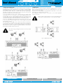
User’s Manual
TEMP
TEMP
PROTECT
PROTECT
SIG/CLIP
SIG/CLIP
R
BRIDGE
-
+
2 1
3
CH A
BRIDGE
-
0
-
0
CH B
INPUTS
GND
OUTPUTS
CH C
BRIDGE
-
0
BRIDGE
D
C
INPUTS
BRIDGE MIN 8
A/B MIN
4
+
PIN1 2
PIN1 2
D
+
C
POWER INPUT
PS amps
0
+
SPEAKER
IMPEDANCE
BRIDGE MIN 8
C/D MIN
4
+
PIN1 2
PIN1 2
BRIDGE
CH D
OUTPUTS
SPEAKER
IMPEDANCE
STEREO
SOUND REINFORCEMENT
PS amplifiers
C-D
A-B
A
B
2 1
3
GND
BRIDGE
A
SERIAL NO:
AC 230V 10%
50Hz-60Hz
CONTROLLED
CONTROLLEDRADIATION
RADIATION
1
B
STEREO
EARTH
USER’S MANUAL
ACOUSTIC RESEARCH
User’s Manual
TEMP
TEMP
PROTECT
PROTECT
SIG/CLIP
SIG/CLIP
PS amplifiers
POWER
R
BRIDGE
-
+
2 1
3
CH A
BRIDGE
-
0
INPUTS
GND
-
0
CH B
OUTPUTS
CH C
BRIDGE
-
0
BRIDGE
D
C
AC 230
50Hz-60H
INPUTS
+
SPEAKER
IMPEDANCE
BRIDGE MIN 8
C/D MIN
4
+
PIN1 2
PIN1 2
BRIDGE
0
OUTPUTS
SPEAKER
IMPEDANCE
STEREO
CH D
BRIDGE MIN 8
A/B MIN
4
+
PIN1 2
PIN1 2
D
+
C
C-D
POWER INPUT
A-B
B
A
STEREO
B
2 1
3
GND
BRIDGE
A
SERIAL NO:
TABLE OF CONTENTS
EARTH
AC 230V 10%
50Hz-60Hz
1. IMPORTANT SAFETY INSTRUCTIONS
pag. 3
2. DECLARATION OF CONFORMITY
pag. 3
3. WARRANTY
pag. 3
4. USER LIABILITY
pag. 4
4.1 Damage to speakers
4.2 Dangerous output voltage
4.3 Radio interferences
5. INTRODUCTION
pag. 4
5.1 Unpacking
5.2 Installation
5.3 Front panels
5.4 Rear panels
6. BRIEF DESCRIPTION OF THE SERIES
pag. 7
7. OPERATING INSTRUCTIONS
pag. 8
7.1 Connection to the AC mains supply and power absorption
7.2 Cooling
7.3 Connection cables
7.4 Configurations
8. PROTECTION SYSTEM FEATURES
pag. 10
8.1 Limiter
8.2 Thermal protection
8.3 Load safety control
8.4 DC protection
8.5 Power on/off transients
9. TESTING PROCEDURE FOR ELECTRO-MECHANICAL OPERATION
pag. 10
9.1 Required equipment
9.2 Visual check
9.3 Electrical testing procedures
10. TECHNICAL SPECIFICATIONS
SOUND REINFORCEMENT
CONTROLLED RADIATION
2
pag. 12
ACOUSTIC RESEARCH
User’s Manual
TEMP
TEMP
PROTECT
PROTECT
SIG/CLIP
SIG/CLIP
PS amplifiers
R
BRIDGE
-
CH A
BRIDGE
-
0
CH B
-
0
1. IMPORTANT SAFETY INSTRUCTIONS
CH C
-
0
CH D
0
2. DECLARATION OF CONFORMITY
2 1
3
INPUTS
GND
OUTPUTS
BRIDGE
This symbol indicates key operating instructions and
information requiring particular attention for correct use+
of the product.
BRIDGE
OUTPUTS
INPUTS
2 1
3
GND
This device complies with the requirements of the European Electromagnetic
Compatibility Directive 89/336/EEC and relevant 92/31/EEC amendment, as
well as the requirements of the Low Voltage Directive 72/23/EEC and relevant
93/68/EE amendment.
Regulations applied:
This symbol warns of dangerous voltage and the
EN55103-1
POWER INPUT
SERIAL NO:(Emissions)
consequent risk of electric shock. Take extra care and
EN55103-2 (Immunity)
proceed with caution.
EN60065, Class I (Safety).EARTH
+
SPEAKER
IMPEDANCE
STEREO
D
C
+
SPEAKER
IMPEDANCE
BRIDGE MIN 8
C/D MIN
4
+
PIN1 2
PIN1 2
BRIDGE
BRIDGE MIN 8
A/B MIN
4
+
PIN1 2
PIN1 2
D
C
C-D
A-B
B
A
STEREO
B
BRIDGE
A
AC 230V 10%
50Hz-60Hz
1. Read carefully all the attached product documentation and keep for
further reference.
2. Heed the warnings.
3. Keep the packaging and check that all the material is in perfect
condition.
4. Do not use the product in the vicinity of water or pour water or any
other liquid on the amplifier. Take care not to use it with wet hands or
with your feet in water.
5. Do not use near sources of heat such as radiators, stoves or other heatproducing appliances.
6. Check that the power cable is intact and undamaged. Do not tread on
the cable and take care not to put any pressure on the plug.
7. Connect the plug to a properly earthed electric socket. Do not tamper
with the plug. Should the plug supplied not fit your socket, have an
electrician replace it with the correct one.
8. Connect to the mains supply having identical voltage as that indicated
on the back of the amplifier.
9. Install the amplifier in compliance with the instructions.
10. Do not obstruct the air ducts.
11. Disconnect the appliance in case of storms or when not in use.
12. Wire exclusively as shown in the instructions.
13. Do not remove the upper or lower covers as this would expose the
user to the risk of electric shock.
3. WARRANTY
Peecker Sound products are guaranteed against malfunction due to defective
materials or workmanship for a specified period of time, starting from the date
of original purchase. Should a malfunction occur during the warranty period,
the product will be repaired or replaced (at the manufacturer’s discretion) free
of charge. The shipping costs and related risks, and any loss during shipment
to authorized service centres are the responsibility of the customer. The
product will be returned to the customer with a carriage forward shipment.
Warranty terms
The warranty covers the appliance under its initial purchase in compliance
with the laws in force. The warranty is valid for 3 years, starting from the date
of receipt of the product. Peecker Sound reserves the right, in certain cases, to
decide to replace the appliance with another identical or similar product. The
warranty is not extended following a product failure. The warranty does not
cover any incidental or consequential damages, without limitation, caused to
persons or property during any period of inefficiency of the appliance.
Exclusions and limitations
The warranty does not apply to:
• any damage to exterior finishings or surfaces, aesthetic elements, or electric/
electronic parts resulting from negligent use of the product;
• malfunction resulting from incorrect or improper use of the product or from
transport without due care;
• malfunction resulting from repairs carried out by unauthorized persons or
service centres;
• malfunction due to circumstances that cannot be ascribed to manufacturing
defects of the appliance;
• plastic or glass parts, bulbs and the like, as well as all that can be regarded
as normal wear and tear. As regards circuit components (transistors, diodes,
etc.) the general terms set by the original manufacturers apply.
The following are also not covered by the warranty:
• damage caused by accidents, product modifications, negligence or incorrect
connection
• damage that occurred during transport
• damage resulting from failure to comply with the instructions contained in
the user’s manual
• claims based on misrepresentations by the seller and any product whose
serial number has been rubbed off, modified or removed.
14. Do not attempt to repair the appliance yourself but always seek the
assistance of qualified technicians.
15. Do not connect an input signal higher than that indicated in the
manual.
16. Do not connect the amplifier output to the input of another channel.
17. Do not connect the amplifier output to any other power source such as
batteries, power supply unit or mains outlets, regardless of whether the
amplifier is switched on or off.
18. Clean with a dry cloth only.
19. The product must be handled by qualified technicians when:
• the power cable or the plug is damaged
• the product has been exposed to rain or humidity
• liquid has got inside the unit
• an object has fallen on the unit
• the unit has fallen and is damaged
• the appliance seems to be malfunctioning or is showing a marked
change in performance
20. Careful supervision is required if the product is used in the presence of
children or by unskilled adults.
21. This appliance may produce sound pressure levels damaging to the
hearing. Take the utmost care and do not use the product for long
periods of time at high or uncomfortable volume levels. Should
you experience any hearing loss or buzzing in your ears, consult an
audiometric specialist.
SOUND REINFORCEMENT
Receiving warranty service
To receive repair or replacement of the product under warranty, the customer
must deliver the product in its original packaging carriage paid to an
authorized Peecker Sound service centre together with the relevant proof of
purchase, i.e. bill of sale, receipt or invoice.
The warranty service and list of authorized service centres is available at the
address below:
Peecker Sound - “After Sales Service”
Via Monti Urali, 29 - 42100 Reggio Emilia (Italy)
Tel: +39 0522 557735 - Fax: +39 0522 391268
E-mail: [email protected]
CONTROLLED
CONTROLLEDRADIATION
RADIATION
3
ACOUSTIC RESEARCH
User’s Manual
TEMP
TEMP
PROTECT
PROTECT
SIG/CLIP
SIG/CLIP
PS amplifiers
POWER
R
BRIDGE
-
CH A
BRIDGE
-
0
-
0
CH B
Repair or replacement of the product and its return to the customer are the
only services provided to the customer. Peecker Sound shall not be held liable
to pay incidental or consequential damages including, without limitation,
injury to persons or property or loss of use.
+
2 1
3
INPUTS
GND
BRIDGE
D
C
D
+
CH D
0
AC 230
50Hz-60H
BRIDGE
OUTPUTS
INPUTS
+
BRIDGE MIN 8
A/B MIN
4
+
PIN1 2
PIN1 2
C
C-D
Costs paid by Peecker Sound
Peecker Sound will pay for all labour and material expenses necessary for the
repairs covered by the warranty. Make sure you keep the original packaging;
POWER INPUT
otherwise, the cost of replacing will be charged to you if necessary. Produce
the original invoice to establish the date of purchase.
AC 230V 10%
50Hz-60Hz
Do not send the product to the factory without prior authorization. Should
shipment of the product be a problem, please contact the service centre, who
will deal with it promptly. Otherwise, the customer is responsible for shipment
and handling of the product to be repaired and payment of all shipping costs.
2 1
3
GND
Congratulations on your choice of a Peecker Sound Professional Series
power amplifier and thank you for your confidence in us and our products.
Your amplifier has been carefully engineered down to the smallest detail,
from component selection to final assembly. All Peecker Sound products
aim for full customer satisfaction and you can rest assured that the product
SERIAL
NO: chosen uses cutting-edge technology.
you
have
The amplifiers have been designed in the Sound Corporation Design and
Research&Development
(R&D) departments paying particular attention
EARTH
to the choice of materials, safety devices and electronic design for the
manufacture of a safe, reliable and long-lasting product.
SPEAKER
IMPEDANCE
BRIDGE MIN 8
C/D MIN
4
+
PIN1 2
PIN1 2
BRIDGE
-
0
5. INTRODUCTION
OUTPUTS
SPEAKER
IMPEDANCE
STEREO
CH C
A-B
B
A
STEREO
BRIDGE
B
A
Since inappropriate use of the product can jeopardize its correct operating
performance, please ensure that you use it carefully and correctly.
Please read this manual carefully: all the information it contains is vitally
important for using your appliance safely.
Limitation of implicit warranties
All implicit warranties, including guarantee of merchantability and suitability
to specific purposes, are limited to the duration of the present warranty. With
the exception of certain types of damage, Peecker Sound liability is limited
to repairing or replacing, at its discretion, any defective products, with no
obligation of compensation for any kind of incidental or consequential
damages. In case of any controversy, the court of jurisdiction will be exclusively
the Court of Reggio Emilia (RE) – Italy.
5.1 Unpacking
Inspect the packaging and its contents immediately to check whether
there are any signs of damage. After unpacking, inspect the product
and any accessories. Should you notice any damage, inform your dealer
immediately.
Please keep all the packaging materials, which will be useful for returning
the product to Peecker Sound or sending it to one of our authorized
Service Centres if the product does not arrive in perfect condition. Use
exclusively the original packaging, as it is the best way to protect the
appliance from mishandling by the carrier.
4. USER LIABILITY
4.1 Damage to speakers
Check the peak power and continuous power of the
amplifiers at all times.
These amplifiers are extremely powerful and may be
potentially dangerous to both speakers and human beings.
Please take care of the environment.
Once the appliance has become obsolete, please
dispose of it in the appropriate recycling container.
Most loudspeaker systems may be easily damaged or broken, often if they are
driven by bridged amplifiers. Although the gain may be attenuated by using
the controls on the front panel of the amplifier, the maximum power output
can still be reached if the input signal is sufficiently high.
5.2 Installation
4.2 Dangerous output voltage
All Peecker Sound Professional Series models can be installed in
standard 19” rack units as shown in Fig. 2. There are four installation holes
on the front panel for optimal securing of the appliance – an important
factor in mobile systems.
Amplifiers can generate dangerous output voltage.
Do not touch any exposed speaker cables while the amplifier
is operating.
4.3 Radio interferences
A sample of this product has been tested and approved in compliance with
the limits set out by the Electromagnetic Compatibility Directive (EMC). These
limits have been determined in order to provide reasonable protection from
dangerous interferences caused by electrical appliances.
Should this product not be installed or used in compliance with the instructions
as set out in this manual, it might interfere with other appliances such as radio
receivers, for example. There is no guarantee, however, that interferences will
not occur in a particular installation.
483 mm
Figure 1. PS amplifier dimensions
Should the device interfere with two-way radios (switching the
device on and off will allow you to check whether this is the
case), you should try to eliminate the interference by adopting
one of the following measures:
A) Increase the distance between the appliance and the receiver.
B) Connect the appliance to a socket positioned on a circuit
different from which the receiver is connected to.
C) Re-position or move the aerial of the receiver.
Check that the unit complies with the EMC immunity limits (it must carry
the CE mark). All electrical appliances sold in the EU must be approved for
immunity to electromagnetic fields, high voltage and radio interferences.
Seek professional assistance.
SOUND REINFORCEMENT
Figure 2. Flight case for pro amplifiers
CONTROLLED RADIATION
4
ACOUSTIC RESEARCH
User’s Manual
TEMP
TEMP
PROTECT
PROTECT
SIG/CLIP
SIG/CLIP
PS amplifiers
R
BRIDGE
-
CH A
BRIDGE
-
0
-
0
CH B
CH C
-
0
CH D
0
5.3 Front panels
+
2 1
3
INPUTS
GND
OUTPUTS
BRIDGE
BRIDGE
OUTPUTS
INPUTS
SPEAKER
IMPEDANCE
STEREO
D
+
SPEAKER
IMPEDANCE
BRIDGE MIN 8
C/D MIN
4
+
PIN1 2
PIN1 2
BRIDGE
C
D
4.a 2
+
C
POWER INPUT
C-D
BRIDGE MIN 8
A/B MIN
4
+
PIN1 2
PIN1 2
3 4.b
A-B
B
A
2 1
3
GND
BRIDGE
STEREO
6
B
A
SERIAL NO:
EARTH
AC 230V 10%
50Hz-60Hz
AMPLIFICATORI PS
Owner’s manual
1
5.3 Pannello frontale
7
8
Figure 3. PS1000 – PS1400 – PS2000 – PS2600 – PS3400 Front panel
2
3
5.a
5.b
6
Owner’s manual
1
7
8
Figure 4. PS650-F front panel
1. CHA/CHB (CHC/CHD) - Precision input level controls that allows the amplification level of each channel to be adjusted.
Note: when using in bridged mode (only applicable to PS650-F, PS1000 and PS1400 amplifiers), the various
level attenuators must be in the same position. We recommend setting them on the 0 position.
2. TEMP - When the temperaturewww.peeckersound.com
LED lights up, the channel gets deactivated as a protection measure against
overheating. The fan will continue to operate so as to bring the temperature down as quickly as possible.
6 is inadequate
via Monti Urali, 33 - 42100
Emilia normally
(Italia) • tel.
+39when
0522there
557735
• fax +39 0522
391288
• e-mail:
[email protected]
Note:Reggio
this situation
occurs
ventilation.
Check
the amplifier
installation
carefully.
3. PROTECT - This protection LED lights up when the load connected is below 1 Ω or the amplifier output has been
short-circuited.
4.a) CLIP - LED indicator for input signal clip point.
4.b) SIGNAL - LED indicator for signal presence.
5.a) SIG/CLIP - Dual-mode LED indicator for both signal presence (green) and signal clip point (red).
5.b) BRIDGE - LED indicator for amplifier operating in bridged mode.
6. POWER - On/Off switch.
7. Ventilation grille for correct amplifier ventilation.
8. 19’’ rack installation holes.
SOUND REINFORCEMENT
CONTROLLED
CONTROLLEDRADIATION
RADIATION
5
ACOUSTIC RESEARCH
10. Switch per il modo d’uso - Selettore modo d’uso: stereo-bridge
11. Connettori d’uscita - Uscite Neutrik® speakON per ogni canale
12. Connettori modalità Bridge - Uscite Neutrik® speakON bridge CHA-CHB, CHC-CHD
13. Power Input - Connettore di alimentazione di tipo 3 pin IEC
14. Commutatore di massa - Consente di collegare o scollegare la massa elettrica alla massa meccanica
15. Griglia per la ventilazione
User’s Manual
TEMP
PROTECT
SIG/CLIP
SIG/CLIP
BRIDGE
-
5.4 Rear panels
TEMP
PROTECT
-
0
CH B
-
0
CH C
POWER
R
BRIDGE
-
0
CH A
PS amplifiers
0
CH D
AC 230
50Hz-60H
AMPLIFICATORI PS
PS1000
2 1
3
+
9
INPUTS
GND
10
OUTPUTS
BRIDGE
OUTPUTS
BRIDGE
INPUTS
SPEAKER
IMPEDANCE
+
SPEAKER
IMPEDANCE
BRIDGE MIN 8
C/D MIN
4
+
PIN1 2
PIN1 2
BRIDGE
STEREO
BRIDGE MIN 8
A/B MIN
4
+
PIN1 2
PIN1 2
STEREO
AMPLIFICATORI PS
D
5.4 Pannello posteriore
C
+
D
C
C-D
A-B
B
A
2 1
3
GND
BRIDGE
B
A
R
TEMP
PROTECT
SIG/CLIP
PS1600
BRIDGE
POWER INPUT
-¡
CH A
SERIAL NO:
0
-¡
0
CH B
5.4 Pannello posteriore
EARTH
AC 230V 10%
50Hz-60Hz
R
11
9
10
TEMP
PROTECT
15
PS1600
12
CH-B OUT
OUTPUT
IMPEDANCE
16 OHM
8 OHM
4 OHM
PIN1+ 2+ £ +
PIN1 2 £ £
CH-A OUT
11
13
SIG/CLIP
BRIDGE
CH-B IN
Figure 5. PS1000 rear panel
-¡
0
CH A
LINK
-¡
Figura 6: Pannello posteriore PS1000
+
£
11
LINK
LINK
+
£
MONO
9
10
9. Connettori d’ingresso - Ingressi Cannon XLR per i due canali e per realizzare il link
10. Switch per il modo CH-B
d’uso
- Selettore modo CH-A
d’uso:
stereo-parallel-bridge
CH-B IN
OUT
OUT
POWER INPUT
11. Connettori d’uscita - Uscite Neutrik® speakON e morsetti a vite
12. Switch per il controllo del limitatore
EARTH
13. Power Input - Connettore
di alimentazione di tipo+ 3 pin
+
£ IEC
£
£
BRIDGE
+
14. Griglia per la ventilazione
AC 230V ¡ 10%
SERIAL NO:
OUTPUT
IMPEDANCE
16 OHM
8 OHM
4 OHM
PIN1+ 2+ £ +
PIN1 2 £ £
LINK
!
¼ÊÒÇ£
BRIDGE
STEREO
+
BRIDGE
£
LINK
CH-A IN
LINK
BALANCED BALANCED
0dB
0dB
30KOHM
30KOHM
OUTPUT
IMPEDANCE
16 OHM
8 OHM
4 OHM
PIN1+ 2+ £ +
PIN1 2 £ £
LINK
15
CH-A IN
LINK
0
CH B
BALANCED BALANCED
0dB
0dB
30KOHM
30KOHM
OUTPUT
IMPEDANCE
16 OHM
8 OHM
4 OHM
PIN1+ 2+ £ +
PIN1 2 £ £
MONO
BRIDGE
STEREO
50Hz £ 60Hz
POWER INPUT
13
14 ÀÉ
1. ðÑÉÒÇ:Ò°ÅÉ, ºÉ×·(³Ê×Í);
2. º°ÑÉÒÇ: Òµº, °É×;
EARTH
Figura
3. ·Á°1:1³, ËÓѸ°ÍÖËÓ;
230V ¡ 10%
! AC50Hz
£ 60Hz
4. ÏÏÒǰɲ¶µÎ×,IQC°É²¶µÒǼ²;
DS-50-2-2-PS1600-A1.0
£Ã°/º°£ËÓ Í
A1.0
7: Pannello posteriore PS1600
www.peeckersound.com
SERIAL NO: R
P S1600
15
R
1
モサイチ
20071208
Ò´À×Ò¹ ·
TEMP
7
via Monti 5.Á×:
Urali,
• fax +39 0522 391288 • e-mail: [email protected]
¼ÊÒÇ£ 33 - 42100 Reggio Emilia (Italia) • tel. +39 0522 557735
PROTECT
13
CLIP
14 ÀÉ
1. ðÑÉÒÇ:Ò°ÅÉ, ºÉ×·(³Ê×Í);
-¡
CH A
0
P S1600
15
SIGNAL
R
FigureFigura
6. PS1400
rear
panel
7: Pannello
posteriore
PS1600
2. º°ÑÉÒÇ: Òµº,
PS2000 - PS2600
- °É×;
PS3400
-¡
CH B
DS-50-2-2-PS1600-A1.0
£Ã°/º°£ËÓ Í
0
A1.0
1
モサイチ
20071208
3. ·Á°1:1³, ËÓѸ°ÍÖËÓ;
11
R
4. ÏÏÒǰɲ¶µÎ×,IQC°É²¶µÒǼ²;
9
Ò´À×Ò¹ ·
TEMP
5.Á×:
9
PROTECT
CLIP
SIGNAL
PS2000 - PS2600 - PS3400
-¡
CH A
-¡
0
CH B
0
11
9
9
Manuale d’uso
5.4 Pannello posteriore
º°ËÓÍXT2000
¼ÊÒÇ£
TEMP
1. ðÑÉÒÇ:Ò°ÅÉ, ºÉ×·(³Ê×Í);
2. º°ÑÉÒÇ: Òµº, °É×;
PS650-F
SIG/CLIP
BRIDGE
3. ·Á°1:1³, ËÓѸ°ÍÖËÓ;
-
CH A
13
PROTECT
P S2000
TEMP
PROTECT
R
SIG/CLIP
Figure 7. PS2000 - PS2600 - PS3400 rear panel
-
0
-
0
CH B
CH C
Figura
8: Pannello posteriore
PS2000 - PS2600 - PS3400CH D
4. ÏÏÒǰɲ¶µÎ×,IQC°É²¶µÒǼ²;
º°ËÓÍXT2000
¼ÊÒÇ£
5.Á×:
9
1. ðÑÉÒÇ:Ò°ÅÉ, ºÉ×·(³Ê×Í);
13
1
Ò´À×Ò¹ ·
P 9S2000
2 1
3
INPUTS
GND
OUTPUTS
BRIDGE
BRIDGE
OUTPUTS
STEREO
C
1
+
SPEAKER
IMPEDANCE
BRIDGE MIN 8
C/D MIN
4
+
PIN1 2
PIN1 2
BRIDGE
A1.0
INPUTS
SPEAKER
IMPEDANCE
D
BRIDGE MIN 8
A/B MIN
4
+
PIN1 2
PIN1 2
D
C
C-D
A-B
B
DS-50-2-2-PS2000-A1.0
£Ã°/º°£ËÓ
Í
15
14
R
10 Cannon XLR per i due canali e16
10
2. º°ÑÉÒÇ:
Òµº, °É×;- Ingressi
9. Connettori
d’ingresso
per realizzare il link
20071208
3. ·Á°1:1³,
ËÓѸ°ÍÖËÓ;
10. Switch per
il modo
d’uso - Selettore modo d’uso:
Figurastereo-mono-bridge
8: Pannello posteriore PS2000 - PS2600 - PS3400
Ò´À×Ò¹ ·
4. ÏÏÒǰɲ¶µÎ×,IQC°É²¶µÒǼ²;
11. Connettori
d’uscita - Uscite Neutrik® speakON e morsetti a vite
5.Á×: - Connettore di alimentazione di tipo 3 pin IEC
12. Power Input
+
13. Commutatore di massa - Consente di collegare o scollegare la massa elettrica alla massa meccanica
9. Griglia
Connettori
14.
per la d’ingresso
ventilazione- Ingressi Cannon XLR per i due canali e per realizzare il link
10. Switch per il modo d’uso - Selettore modo d’uso: stereo-mono-bridge
11. Connettori d’uscita - Uscite Neutrik® speakONPOWER
e morsetti
aSERIAL
viteNO:
INPUT
12. Power Input - Connettore di alimentazione di tipo 3 pin IEC
13. Commutatore di massa - Consente di collegare o scollegare la massa elettrica alla massa meccanica
EARTH
AC 230V 10%
14. Griglia per la ventilazione
50Hz-60Hz
www.peeckersound.com
+
A1.0
モサイチ
20071208
0
11
ÀÉ
DS-50-2-2-PS2000-A1.0
R
£Ã°/º°£ËÓ
Í
15
14
BRIDGE
-
0
ÀÉ
A
STEREO
2 1
3
モサイチ
GND
BRIDGE
B
P S 6 5 0 -F
A
DS -50-2-2-P S 650-F -A1.0
8
140522 391288 • e-mail:
15 [email protected]
via Monti Urali, 33 - 42100 Reggio Emilia (Italia) • tel. 13
+39 0522 557735
• fax +39
/
A1.0
R
Figure 8. PS650-F Rear panel
20071208
1
Figura 5: Pannello posteriore PS650-F
www.peeckersound.com
9. Inputs -(CHA
IN/
CHB IN)
Cannon®
XLR inputs for each channel.
9. Connettori d’ingresso
Ingressi
Cannon
XLR–per
ogni canale
8
via Monti Urali,Operating
33 - 42100 Reggio Emilia
(Italia)–•Operating
tel. +39 0522mode
557735
• fax +39 0522 391288 • e-mail: [email protected]
switch
10. Switch per10.
il modo d’uso - mode
Selettore
modo d’uso:
stereo-bridge selection switch: mono, stereo, parallel or bridge.
®
11. Connettori11.
d’uscita
- Uscite
Neutrik
speakON
per ogni
canale SpeakOn output connectors for each channel.
Outputs
(CHA
OUT/
CHB OUT)
– Neutrik®
®
12. Connettori12.
modalità
- Uscite
Neutrik
speakON
bridge
CHA-CHB,
CHC-CHD
Limit -Bridge
Limiter
control
switch.
LIMIT ON:
soft
clip limiter
enabled, LIMIT OFF: disabled.
13. Power Input
Connettore
di alimentazione
tipo 3 pin
IEC connector.
13.- Power
Input
– IEC 3-pindipower
supply
14. Commutatore di massa - Consente di collegare o scollegare la massa elettrica alla massa meccanica
14. Earth - Ground lift that allows connection-disconnection of electrical earth to/from mechanical earth.
15. Griglia per la ventilazione
15. Ventilation grille.
16. Bridge - CHA-CHB, CHC-CHD outputs with Neutrik® SpeakON connectors for bridge mode.
PS1000
SOUND REINFORCEMENT
CONTROLLED RADIATION
9
10
6
ACOUSTIC RESEARCH
User’s Manual
Owner’s
manual
Manuale d’uso
TEMP
TEMP
PROTECT
PROTECT
SIG/CLIP
SIG/CLIP
BRIDGE
-
CH A
6. Breve
descrizione
6. BRIEF
DESCRIPTION
OF THE SERIES della
2 1
3
CH B
-
0
-
0
OUTPUTS
BRIDGE
D
CH D
0
OUTPUTS
BRIDGE
INPUTS
SPEAKER
IMPEDANCE
STEREO
C
D
C
only
only
11
11 Kg!
Kg!
+
SPEAKER
IMPEDANCE
BRIDGE MIN 8
C/D MIN
4
+
PIN1 2
PIN1 2
BRIDGE
AC 230V 10%
50Hz-60Hz
BRIDGE MIN 8
A/B MIN
4
+
PIN1 2
PIN1 2
C-D
A-B
B
A
STEREO
2 1
3
GND
BRIDGE
B
A
SERIAL NO:
t.VMUJBQQMJDBUJPO
t.VMUJBQQMJDBUJPO
EARTH
t)JHIUFDIOPMPHZ
t)JHIUFDIOPMPHZ
t-JHIUOFTT
• t-JHIUOFTT
Durability
t)JHIQPXFSFGmDJFODZ
t)JHIQPXFSFGmDJFODZ
only
only
11
11 Kg!
Kg!
PS1600
PS1000
PS1000
XTDT3200
CH C
gamma
INPUTS
GND
R
BRIDGE
-
0
Gli amplificatori Professional Series sono disponibili in sei modelli
Professional Series amplifiers are available in six models,
differenti per
potenza
e numero
canali.
I modelli
PS1000,
differentiated
according
to power
ratingsdiand
number
of channels.
+
PS1600,
PS2000,
PS2600,
PS3400
a duemodels
canali ed
PS1000,
PS1400,
PS2000,
PS2600,
andsono
PS3400
areerogano
twochannel
amplifiers
capable
fromcanale
450 Wa up
to Il1700
W
potenze
da 450
W finoofa delivering
1700 W per
4 Ω.
modello
per PS650-F
channel onto
4 Ω.dispone
PS650-Fdimodel,
contrast,
has four
650 W a
invece,
quattrobycanali
da 650
W sempre
channels,
also onto
4 Ω.
POWER INPUT
4 Ω. Tutti
gli amplificatori
della linea Professional Series sono
All Professional Series amplifiers have been designed to meet the
stati requirements
progettati per ofle the
specifiche
nel campo
specific
world esigenze
of professional
audiodell’audio
based
professionale,
secondo
criteri diand
massima
e funzionalità
on criteria
of maximum
reliability
ease ofaffidabilità
use. Power
delivery
remains
constant
even at highdiloads,
with risulta
low heat
dissipation
andad
d’impiego.
L’erogazione
potenza
costante
anche
highalti
performance
thanks
low-leakage
toroidal
transformers,
regimi, con
una to
bassa
dissipazione
termica
ed un which
elevato
provide
an extra grazie
margin all’impiego
above the stated
nominal output.
The apower
rendimento
di trasformatori
toroidali
basse
supply unit is protected against possible overvoltages, overheating
perdite
che
garantiscono
un
margine
esteso
al
di
sopra
dell’uscita
and short circuiting.
dichiarata.
L’alimentatore
risulta protetto
Eachnominale
of the power
stage modules
is fully independent
in contro
terms ofpossibili
both
electrical
and thermal
protections. Each
channel, inOgni
fact, is
equipped
sovratensioni,
surriscaldamenti
o cortocircuiti.
modulo
finale
withrisulta
its own
heat sink and indipendente
independent sia
temperature
controlelettriche
which
completamente
nelle protezioni
acts che
directly
on the
cooling fan.
in quelle
termiche,
infatti ciascun canale possiede un proprio
The signal is constantly monitored, with the LED light on the front
dissipatore
e
un
controllo
della
indipendente che agisce
panel checking and indicating
thetemperatura
level.
direttamente
ventola
di raffreddamento.
E’ costantemente
An internal
limitersulla
provides
loudspeaker
system protection
against
signal
distortion. ilThe
mechanical
subsequent
monitorato
segnale,
conconstruction
controllo eand
indicazione
delcircuit
livello
engineering
are sul
such
as to frontale.
guarantee
production
tramite LED
pannello
Unhigh
limitatore
interno standards.
permette di
Thanks
to its rigid
chassis,dai
thedanni
amplifier
is able
to withstand
even
proteggere
glisteel
altoparlanti
dovuti
a segnali
in distorsione.
the toughest tours, guaranteeing maximum reliability in all operating
La costruzione meccanica e la successiva lavorazione sono tali
conditions.
da garantire elevati standard di fabbricazione. Il rigido chassis in
acciaio rende l’amplificatore capace di sopportare anche i tour più
impegnativi garantendo sempre la massima affidabilità in qualsiasi
condizione operativa.
+
PS amplifiers
PS2000
PS1400
PS2000
XTDT3800
XTDT3200
Output
Power @ 4 Ohm
2 x 450 W*
Output Power @ 4 OhmXTDT3800
2 x 700 W*
Output Power @ 4 Ohm
2 x 1000 W*
Output Power @ 8 Ohm
2 x 280 W*
Output Power @ 8 Ohm
2 x 450 W*
Output Power @ 8 Ohm
2 x 650 W*
only
only
13
13 Kg!
Kg!
only
only
13
13 Kg!
Kg!
PS2600
PS2600
XTDT4800F
XTDT4800F
PS3400
PS3400
XTDT6000F
XTDT6000F
PS650-F
PS650-F
Output Power @ 4 Ohm
2 x 1300 W*
Output Power @ 4 Ohm
2 x 1700 W*
Output Power @ 4 Ohm
2 x 650 W*
Output Power @ 8 Ohm
2 x 850 W*
Output Power @ 8 Ohm
2 x 1000 W*
Output Power @ 8 Ohm
2 x 300 W*
* EIA 1 kHz - 1% THD, both ch.s driven @ 230 VAC
www.peeckersound.com
SOUND
REINFORCEMENT
CONTROLLED
CONTROLLED
RADIATION
ACOUSTIC
RESEARCH
9RADIATION
via Monti Urali, 33 - 42100 Reggio Emilia (Italia) • tel. +39 0522 557735
• fax +39 0522 391288 • e-mail:
[email protected]
7
User’s Manual
TEMP
TEMP
PROTECT
PROTECT
SIG/CLIP
SIG/CLIP
PS amplifiers
POWER
R
BRIDGE
-
CH A
BRIDGE
-
0
-
0
CH B
7. OPERATING INSTRUCTIONS
+
2 1
3
INPUTS
GND
OUTPUTS
SPEAKER
IMPEDANCE
D
C
D
CH D
0
AC 230
50Hz-60H
BRIDGE
OUTPUTS
INPUTS
+
SPEAKER
IMPEDANCE
BRIDGE MIN 8
C/D MIN
4
+
PIN1 2
PIN1 2
BRIDGE
-
0
• Using in stereo mode (standard)
When using in stereo mode, each channel operates independently and
the dedicated input attenuators control the respective channel level.
The recommended minimum load for using in stereo mode is 4 Ω per
channel for all Peecker Sound Professional Series models (see Technical
Specifications). To connect the input signal, use the Cannon XLR connectors
on the rear panel. The loudspeaker systems must be connected to the
Neutrik®
SpeakOn output connectors.
SERIAL NO:
BRIDGE
7 .1 Connection to the AC mains supply and power absorption
STEREO
CH C
BRIDGE MIN 8
A/B MIN
4
+
PIN1 2
PIN1 2
+
C
C-D
Check that your mains power supply is sufficient for the power requirement of
your amplifier (consult the data at the end of this manual). Note that the voltage
of the electric mains should correspond to the voltage indicated on the back of
POWER INPUT
the amplifier. Maximum current absorption is limited by internal fuses.
A-B
Note: Remember that before connecting any of the cables
it is always better to switch off and disconnect the amplifier
from the power supply. When switching on the amplifier, the
volume controls should always be set to the lowest level.
B
A
STEREO
B
2 1
3
GND
BRIDGE
A
EARTH
AC 230V 10%
50Hz-60Hz
7 .2 Cooling
Pay particular attention to the ventilation/cooling conditions of the amplifiers.
An internal system of forced airflow by means of a variable speed fan allows
the heat sinks to cool down from the heat generated by power parts. The air
flows from the front panel of the amplifier to its rear panel, so that the air is
drawn in from the front opening and let out through the back opening.
Figure 10. Stereo Mode PS650-F
Ensure that there is sufficient space in front of the appliance to allow
adequate inflow and outflow of air. With rack installation, make sure there
are sufficient openings for air to flow freely through the amplifier.
7 .3 Connection cables
To connect the amplifier to the speakers, always use suitable cables to avoid
amplifier power dispersion due to inadequate cable section.
When connecting the amplifier to the mixer, only use shielded cables and
not electric power cables. The main inputs and outputs are connected using
Cannon® XLR and Neutrik® SpeakOn connectors.
7 .4 Configurations
Figure 11. Stereo Mode PS1000
XLR BAL INPUT/OUTPUT
Pin 1
GND
Pin 2
HOT +
Pin 3
COLD -
Neutrik ® speakON
Pin 1 +
POS (CH1 CH3)
Pin 1 -
NEG (CH1 CH3)
Pin 2 +
POS (CH2 CH4)
Pin 2 -
NEG (CH2 CH4)
Figure 12. Stereo Mode PS1400
Figure 9. Cannon® XLR and Neutrik® SpeakOn connectors
Make sure the unit is switched off before configuring according to your
requirements. To turn on the unit, use the ON/OFF switch located on the
right of the front panel. To adjust the volume of individual channels turn the
corresponding knobs, i.e. ChA/ChB for PS1000, PS1400, PS2000, PS2600 and
PS3400 and ChA/ChB/ChC/ChD for PS650-F.
With audio systems it is always better to switch off the amplifier first. Remember
to switch off the amplifier before connecting or disconnecting it to other units
and always switch on the mixer first and then the amplifier, in order to avoid
peaks that could cause disturbances and may damage the speakers.
SOUND REINFORCEMENT
Figure13. Stereo Mode PS2000 – PS2600 – PS3400
CONTROLLED RADIATION
8
ACOUSTIC RESEARCH
User’s Manual
TEMP
TEMP
PROTECT
PROTECT
SIG/CLIP
SIG/CLIP
PS amplifiers
R
BRIDGE
-
CH A
BRIDGE
-
0
CH B
-
0
CH C
-
0
CH D
0
• Using in mono bridge mode
• Parallel inputs
To activate the mono bridge mode, set the switches on the rear panel on
Parallel mode is activated using the dedicated switches on the rear panel.
the Bridge position. This configuration is only available in PS650-F, PS1000
When operating in parallel mode, the inputs of both channels are connected
and PS1400 models. Using in mono bridge mode requires both amplifier
and receive the same signal.
channels (A and B, C and D) to operate with the same input signal+ This function is only available in models PS1000 and PS1400. To connect the
but with inverted phases. Power values can be found in the technical
input signal, use Cannon® XLR connectors.
specifications table at the end of this manual.
The loudspeaker systems must be connected to the Neutrik® SpeakOn
To use the PS650-F model in mono bridge mode, the input signal
output
connectors.
POWER INPUT
SERIAL NO:
necessarily has to be connected to Ch A (for bridging between Ch
A and Ch B) and to Ch C (for bridging between Ch C and Ch D). The
Make sure that only the inputs are connected in parallel. Never
EARTH
corresponding volume is adjusted using the potentiometers of Ch A and
earth positive
output terminals or connect them in parallel.
Ch C. Make sure that the level attenuators are in the same position.
In the case of PS1000, the input signal necessarily has to be connected
to Ch A and the corresponding volume is thus adjusted using the
potentiometer of Ch A.
The input signal for PS1400, on the other hand, must necessarily be
connected to Ch A and the corresponding volume is thus adjusted by
the potentiometer of Ch A. To connect the input signal, use the Cannon®
XLR connectors on the rear panel. The speakers must be connected to
the Neutrik® SpeakOn output connectors.
+
2 1
3
INPUTS
GND
OUTPUTS
BRIDGE
BRIDGE
OUTPUTS
INPUTS
SPEAKER
IMPEDANCE
STEREO
D
C
+
SPEAKER
IMPEDANCE
BRIDGE MIN 8
C/D MIN
4
+
PIN1 2
PIN1 2
BRIDGE
BRIDGE MIN 8
A/B MIN
4
+
PIN1 2
PIN1 2
D
C
C-D
A-B
B
A
STEREO
B
2 1
3
GND
BRIDGE
A
AC 230V 10%
50Hz-60Hz
Note: when using in bridge mode do not connect loads
under 8 Ω.
Figure 17. Parallel Mode PS1000
Figure 14. Bridge Mode PS650-F
Figure 18. Parallel Mode PS1400
Figure 15. Bridge Mode PS1000
Figure 16. Bridge Mode PS1400
SOUND REINFORCEMENT
CONTROLLED
CONTROLLEDRADIATION
RADIATION
9
ACOUSTIC RESEARCH
User’s Manual
TEMP
TEMP
PROTECT
PROTECT
SIG/CLIP
SIG/CLIP
POWER
R
BRIDGE
-
CH A
BRIDGE
-
0
CH B
-
0
8. PROTECTION SYSTEM FEATURES
CH C
-
0
CH D
0
AC 230
50Hz-60H
9. TESTING PROCEDURE FOR ELECTRO-MECHANICAL OPERATION
All Peecker Sound Professional Series amplifiers are equipped with
powerful systems to protect the amplifier and its load.
+
Protection systems are designed to ensure that power amplifiers have a long
operating life.
+
2 1
3
INPUTS
GND
OUTPUTS
D
C
D
BRIDGE
OUTPUTS
INPUTS
+
SPEAKER
IMPEDANCE
BRIDGE MIN 8
C/D MIN
4
+
PIN1 2
PIN1 2
BRIDGE
The testing protocols for the various series of amplifiers manufactured
by Sound Corporation (XTDT series by X-Treme and PSDSP and PS series
by Peecker Sound) have been designed according to the FMEA (Failure
Mode and Effect Analysis) method.
This is a risk assessment system deriving from electro-mechanical
reliability studies used widely in industrial and non-industrial sectors to
SERIAL NO:
evaluate the reliability of both products and processes. FMEA consists
of procedures for analysing potential failures; they are repeatable,
EARTH
transparent and guarantee
total control of the operating functions and
absolute reliability of the manufactured products.
BRIDGE
SPEAKER
IMPEDANCE
STEREO
8.1 Limiter
PS amplifiers
BRIDGE MIN 8
A/B MIN
4
+
PIN1 2
PIN1 2
C
C-D
POWER INPUT
When the CLIP LED lights up, the limiter is active. In this case the channel
gain will be reduced automatically to protect the load (acoustic speakers)
from damage caused by a distorted signal.
The limiter circuit cannot be deactivated, except for the PS1000 amplifier.
AC 230V 10%
50Hz-60Hz
A-B
B
A
STEREO
2 1
3
GND
BRIDGE
B
A
FMEA results basically consist of the following two documents:
• The first is an internal Sound Corporation tool designed for the Product
Development Department with an indication of the various critical areas
detected and suggested actions for improvement, such as increasing
MTTF (Mean Time to Failure) and/or the life cycle of the amplifier under
investigation.
• The second arises from detailed knowledge of failure modes and is
used to determine precisely the amplifier correct operating conditions
as well as the corresponding checking operations.
This procedure is also available to the final customer in the form of
checking procedure for the amplifier correct electro-mechanical
operation, as provided below.
8.2 Thermal protection
The temperature level of the heat sink is constantly monitored, as indicated by
the TEMP LED. When the heat sink temperature goes above 60° C the cooling
fan switches on, while at 90° C (anomalous operating condition) the TEMP LED
lights up and the whole system goes into mute mode until the temperature
returns to normal levels.
8.3 Load safety control
The state of the input signal in Peecker Sound amplifiers is constantly
monitored. Should the power load exceed the maximum allowable level,
the output voltage will be automatically readjusted so that the amplifier
can operate safely. Should the connected load impedance be significantly
below recommended levels, the amplifier output phase will be inhibited.
Note: Before removing any module or connector,
remember to disconnect the amplifier from the mains and
take care when handling power supply capacitors as they
might be under load.
8.4 DC Protection
To prevent short-circuits during testing, the oscilloscope must be earth
insulated. Do not test the amplifier while the speakers or cones are output
connected, use the appropriate dummy loads only. When increasing the
output voltage of the variable voltage transformer (Variac), never exceed
the amplifier nominal output value plus its tolerance, since higher voltage
levels might seriously damage the amplifier.
The presence of a DC voltage is monitored on both channels independently.
If a value equal to or above 7 Volts is detected, the amplifier output stage will
be inhibited. This protects the speakers against DC voltage.
8.5 Power on/off transients
9 .1 Required equipment
To eliminate power on/off transients, which can damage the loudspeaker
systems, a soft start circuit is enabled that connects the load with delay and
disconnects it immediately.
List of testing equipment:
• Digital multimeter
• AC millivoltmeter
• Dual trace oscilloscope
• Audio signal generator
• 15A-250V Variac
• Two 4 Ω (1800W) dummy loads
• Two 8 Ω (1100W) dummy loads
• Audio Precision (AP) analyser
• Vibrating table for mechanical testing
• Withstanding voltage tester
9 .2 Visual check
Check that the product is correctly assembled and verify whether there
are any incorrectly mounted or damaged parts, open connections or
short circuits.
SOUND REINFORCEMENT
CONTROLLED RADIATION
10
ACOUSTIC RESEARCH
User’s Manual
TEMP
TEMP
PROTECT
PROTECT
SIG/CLIP
SIG/CLIP
PS amplifiers
R
BRIDGE
-
CH A
BRIDGE
-
0
CH B
-
0
CH C
-
0
CH D
0
9 .3 Electrical testing procedures
1. Use the withstanding voltage tester to test the amplifier: turn off the
6. Dynamic testing:
amplifier, set the voltage testing level at 1500 V and the test time at 60
• Set a sinusoidal signal at 1 kHz (set the signal level at a value close to clip
seconds. If the leakage current does not go above 5 mA the test has+
LED activating signal).
been successful.
• Connect a 4 Ω load (of suitable power) in one channel only. The output
2. Check the whole unit thoroughly for any short circuits using the
signal voltage should be: 57 V (PS650-F), 47 V (PS1000), 56 V (PS1400), 72 V
multimeter. Verify that the voltage supply and earthing are correct
(PS2000),
82 V (PS2600), 92 V (PS3600).
POWER INPUT
SERIAL NO:
and that the power supply cable is undamaged. After the amplifier has
• Check that the output waveform is regular. Shake the input/output
been turned on once, make sure there are no short circuits.
connectors to check that they are reliable and there are no faulty contacts.
3. Using the Variac, set the power supply in the primary coil of the
7. Signal LED test: checkEARTH
that the LED lights up when there is an input signal
transformer at 230 V. This voltage value has to be monitored and
(set the Gain of each channel at maximum level).
adjusted in order to be kept constant throughout the duration of
8. Make sure that the crosstalk is greater than or equal to 50 dB (≤ 50 dB).
the test. Turn the amplifier on and off six times to check whether the
9. Check that the CMRR (@ 1kHz) is greater than or equal to 60 dB (≤ 60 dB).
power switch works correctly, the relays are activated (with a certain
10. Check the phase between output and input.
amount of delay), and both protection LEDs are flashing.
11. Connect the 8 Ω loads on both channels, set the volume to maximum
4. Check that the voltages in the power supply module are as follows:
level and check that there is no background noise due to the power supply
• PS650-F:
transformer.
A) AC voltage values in the secondary coil should be:
12. Test the frequency response: 20 Hz-20 kHz ±0.5 dB.
65V---0---65V, 20V---0---20V, 17V---0---17V, 0---10V.
13. Bring the heat sink temperature to 50° C (PS650-F, PS1400, PS2000, PS2600,
B) DC voltage on the amplifier modules should be ±89 V.
PS3400) or 70° C (PS1000) and check that the fans are operating (and
(tolerance: ±1V).
noiseless).
C) Protection circuits power supply voltage: ±24 V.
14. Check that, at maximum output power, the current is:
(tolerance ±2 V).
• PS650-F: 6 A with an 8 Ω load; 10 A with a 4 Ω load
D) Fans power supply voltage: -24V (tolerance ±2 V).
• PS1000: 6 A with an 8 Ω load; 10 A with a 4 Ω load
E) Power supply voltage in the pre-amplifier module: ±12 V
• PS1400: 7 A with an 8 Ω load; 13 A with a 4 Ω load
(tolerance ≤ ±0.5V).
• PS2000: 9 A with an 8 Ω load; 15 A with a 4 Ω load
• PS1000:
• PS2600: 10 A with an 8 Ω load; 18 A with a 4 Ω load
A) AC voltage values in the secondary coil should be:
• PS3400: 11 A with an 8 Ω load; 20.5 A with a 4 Ω load
56V---0---56V (GRN---BLK---BLU).
15. Output protection test: short-circuit the output with 0 Ω and check that the
B) DC voltage on the amplifier module should be ±77 V.
protection system activates (the relays should disconnect the load).
C) Fans’ power supply voltage: +24 V.
16. Adjust the mains power supply voltage (using the Variac) from 205 V to 255V
• PS1400:
and check that the amplifier is operating correctly.
A) AC voltage values in the secondary coil should be:
17. Check that the THD (@ 1kHz) is less than or equal to 0.08% with an 8Ω load.
65V---0---65V (GRN---BLK---GRN), 19V---0---19V (BLU---BLK---BLU),
18. Test for vibrations and correct amplifier operation using the vibrating table
17V---0---17V (YEL---BLK---YEL), 0---10V (WHI---WHI).
for mechanical tests:
B) DC voltage on the amplifier module should be ±88 V.
• Vibration frequency: 5-60 Hz
C) Fans’ power supply voltage: +24 V.
• Direction: vertical, horizontal
• PS2000-PS2600-PS3400
• Test duration: 180 seconds
A) AC voltage values in the secondary coil should be:
• Check that there is no output signal after the vibration test has been
56V---0---56V (PS3400), 50V---0---50V (PS2600), 45V---0-45V (PS2000).
performed.
All models must have the following AC output voltage values:
19. Burn-in test
19V---0---19V, 17---0---17V, 0---10V.
• Using a Pink Noise generator, set the input signal so as to obtain 1/8 of
B) DC voltage on the amplifier modules should be:
nominal output power @ 4Ω.
±78 V (PS3400), ±68 V (PS2600), ±61 V (PS2000)
• Check that the Clip LEDs light up occasionally though not too repeatedly.
(tolerance: ±1 V).
• After 4 hours of testing, check general operating functions.
C) Protection circuits power supply voltage: ±24V (tolerance ±2 V).
D) Fans power supply voltage: +24 V.
E) Power supply voltage in the pre-amplifier module: ±12 V.
(tolerance ≤ ±0.5 V).
5. Check that the background noise in both channels is below 1 mV (-58
dBu) and that there is no signal after switching off the unit. Use the
oscilloscope to perform this test, connecting a speaker for a sound
check if necessary.
5.a. (Only applicable to PS2000 – PS2600 – PS3400)
Measure the voltage on collectors for Q104, Q103, Q204 and Q203 and
check that it is ±1.2 V. If necessary, adjust the 1 kΩ trimmer so that this
value has a tolerance level less than or equal to ±0.1 V (≤ ±0.1 V). The
output terminal DC voltage must be less than or equal to 10 mV (≤ 10
mV).
+
2 1
3
INPUTS
GND
OUTPUTS
BRIDGE
BRIDGE
OUTPUTS
INPUTS
SPEAKER
IMPEDANCE
STEREO
D
C
+
SPEAKER
IMPEDANCE
BRIDGE MIN 8
C/D MIN
4
+
PIN1 2
PIN1 2
BRIDGE
BRIDGE MIN 8
A/B MIN
4
+
PIN1 2
PIN1 2
D
C
C-D
A-B
B
A
STEREO
B
2 1
3
GND
BRIDGE
A
AC 230V 10%
50Hz-60Hz
SOUND REINFORCEMENT
CONTROLLED
CONTROLLEDRADIATION
RADIATION
11
ACOUSTIC RESEARCH
User’s Manual
TEMP
TEMP
PROTECT
PROTECT
SIG/CLIP
SIG/CLIP
PS amplifiers
POWER
R
BRIDGE
-
CH A
BRIDGE
-
0
-
0
CH B
CH C
-
0
0
CH D
AC 230
50Hz-60H
10. TECHNICAL SPECIFICATIONS
+
MODEL
2 1
3
INPUTS
GND
OUTPUTS
SPEAKER
IMPEDANCE
STEREO
D
PS1000
BRIDGE MIN 8
C/D MIN
4
+
PIN1 2
PIN1 2
BRIDGE
C
D
+
BRIDGE
PS1400
C
C-D
OUTPUTS
BRIDGE
INPUTS
SPEAKER
IMPEDANCE
PS2000
A-B
B
PS2600
BRIDGE MIN 8
A/B MIN
4
+
PIN1 2
PIN1 2
STEREO
A
B
BRIDGE
+
2 1
3
GND
PS3400
PS650-F
A
Power Output (per channel)
8Ω
280 W*
4Ω
450 W*
POWER INPUT
SERIAL NO:
450 W*
650 W*
850 W*
1000 W*
300 W*
1300 W*
1700 W*
650 W*
EARTH
AC 230V 10%
50Hz-60Hz
700 W*
1000 W*
Bridged Mono Power
8Ω
880 W*
1300 W*
Net Weight
14 kg
22 kg
Frequency Response
20 Hz ÷20 kHz (± 0.5 dB)
SNR
> 100 dB
Distortion (THD+N)
< 0.1% (@ 1 kHz)
Level adjustment (per channel)
-∞ ÷ 0 dB
/
/
/
32 kg
32 kg
33 kg
1200 W*
* EIA 1 kHz - 1% THD, both ch.s driven @ 230 VAC
Input Impedance
30 kΩ, electronically balanced
Input Sensitivity
0 dBu
Crosstalk
> 50 dB
Phase Response
-18° (@ 20 Hz), +25° (@ 20 kHz)
Damping Factor
> 200 (@ 8 Ω, 1 kHz)
Input Connectors (per channel)
3-pin Cannon® XLR
Output Connectors (per channel)
Neutrik® speakON, screw terminals (except for PS650-F)
Controls
Front: power switch, ChA/ChB (PS650-F: ChC/ChD) gain potentiometers
Rear: mode, limit or ground lift switches
Led Indicators
Temperature, Protect, Clip, Signal, (PS1400, PS650-F: Bridge)
Amplifier Protections
overload, full short circuit, thermal, ultrasonic and radio frequency immunity
Load Protections
soft start, soft clip limiter, DC-fault
Circuitry
class AB
Cooling
front to rear air flow, fan speed in function of temperature
Power Requirements
230 VAC (± 10%) , 50/60 Hz
Dimensions (W×H×D)
483 (19”) × 132 (3 RU) × 487 mm (PS100: 483 (19”) × 88 (2RU) × 388 mm)
Approvals
CE EN55103-1 (Emissions), CE EN55103-2 (Immunity), CE EN6065, Class I (Safety)
SOUND REINFORCEMENT
CONTROLLED RADIATION
12
30 kg
ACOUSTIC RESEARCH