1
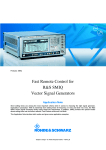
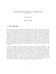
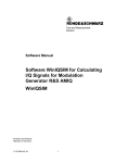
Products: Vector Signal Generator SMIQ SMIQB60 Arbitrary Waveform Generator for SMIQ The SMIQB60 option is an internal two channel arbitrary waveform generator based on the modulation coder SMIQB20. SMIQB60 uses an innovative interpolation filter technique to increase memory capacity. Waveforms can be calculated and transmitted with the external PC-Software WinIQSIM and stored in the non volatile memory of SMIQ. Stored waveforms can be recalled by SMIQ without using WinIQSIM. Subject to change – Dr. René Desquiotz, Hans-Jörg Strufe 08/2002– 1GP45_1E SMIQB60 Arbitrary Waveform Generator Contents 1 Introduction..............................................................................................2 2 Function Principles of SMIQB60..............................................................3 Conventional arbitrary waveform generators......................................3 Functioning of an interpolation filter....................................................4 SMIQB60 concept ..............................................................................7 3 SMIQB60 Operation ..............................................................................10 Generating waveforms with WinIQSIM .........................................10 Programming triggers with WinIQSIM ..........................................11 Clock Settings ..................................................................................11 ARB menu in SMIQ ..........................................................................12 Dynamic range .................................................................................13 Calibration ........................................................................................14 4 Applications ...........................................................................................15 CW multi carrier signals ...................................................................15 Digital standards...............................................................................15 GSM/EDGE .................................................................................16 NADC ..........................................................................................16 cdmaOne (IS-95).........................................................................16 cdma2000 1X/3X.........................................................................17 W-CDMA (3GPP FDD)................................................................17 5 Additional Options related to SMIQB60 .................................................18 6 Software cal_iqskew for SMIQB60 Calibration......................................20 Installing cal_iqskew.........................................................................20 Calibration setup...............................................................................20 Calibrating SMIQB60........................................................................21 Equipment setup .........................................................................21 Automatic calibration ...................................................................21 Manual calibration .......................................................................21 Quit..............................................................................................22 7 References ............................................................................................23 8 Ordering information..............................................................................23 1 Introduction The SMIQ option SMIQB60 is an internal 2 channel arbitrary waveform generator (ARB) based on the modulation coder SMIQB20. Waveforms can be calculated and transmitted with the external PC-Software WinIQSIM and stored in the non volatile memory of SMIQ. Stored waveforms can be recalled by SMIQ without using WinIQSIM. SMIQB60 provides arbitrary I/Q signals to drive SMIQ's I/Q modulator. This is the main purpose of SMIQB60, although the I/Q signals are also available at SMIQ's I and Q outputs. SMIQ is based on a concept providing considerable improvements compared to conventional arbitrary waveform generators. This concept is outlined in section 2. Sections 3 and 4 describe SMIQB60 operation and applications. 1GP45_1E 2 Rohde & Schwarz SMIQB60 Arbitrary Waveform Generator 2 Function Principles of SMIQB60 Conventional arbitrary waveform generators RAM D A Fig. 2.1 Conventional ARB A conventional arbitrary waveform generator (ARB) basically consists of an output-memory, a D/A-converter and an analog filter (see Fig. 2.1). Fig. 2.2 Building a sinewave with a conventional ARB. Upper row: time domain. Lower row: frequency domain. Fig. 2.2 shows how a signal is generated with a conventional ARB. A sinewave with frequency 1 MHz is taken as example. The sinewave is represented by a sequence of sample values stored in the waveform RAM. Mathematically, this is described as a sequence of weighted Dirac pulses. The time interval between two consecutive sample values is given by Tsample= 1 / fsample, with fsample being the sample rate. This time signal and the resulting frequency spectrum are shown in the left column of Fig. 2.2 A sequence of Dirac pulses in time domain gives a sequence of Dirac pulses in frequency domain. The fundamental at fmod (modulation frequency) is repeated at fsample ± fmod, 2*fsample ± fmod , and so on. These repetitions are called aliasing products. As the sample rate is 12 MHz, and fmod = 1 MHz, there are aliasing products at 11 and 13 MHz, 23 and 25 MHz, and so on. Actually, this is not quite the signal coming out of the D/A converter. As we want a continuous output signal, every sample value has to be held for Tsample. Thus, the signal from the D/A converter is a sequence of rectangles with amplitudes 1GP45_1E 3 Rohde & Schwarz SMIQB60 Arbitrary Waveform Generator given by the sample values and widths Tsample. This leads to an additional (sin fsample) / fsample factor in the spectrum, as shown in the middle column. As the fundamental contains all necessary information about the signal, the aliasing products are normally suppressed by low-pass filters to reduce the bandwidth of the signal chain, see the right column in Fig. 2.2. In our example, the filter cutoff has to be at 11 MHz at maximum to suppress all aliasing products (see Fig. 2.3). Fig. 2.3 1 MHz sinewave signal with 12 MHz sample rate and 11 MHz filter cutoff. Usually, the antialiasing filters in ARBs are hardware filters with fixed passband and stopband range, the signal calculation has to be adapted to the filter characteristics. (In our example, the sample rate has to be at least 12 MHz to make use of the 11 MHz filter.) This can lead to high oversampling values and therefore to a large amount of sample values using up RAM capacity. The ARB concept has been significantly improved in the SMIQB60 option. The core of this improved concept is using a digital interpolation filter. Functioning of an interpolation filter Fig. 2.4 1 MHz sinewave with 12 MHz sample rate (time domain) Let us have a closer look at how an interpolation filter works with a simple example. In Fig. 2.4 a 1 MHz sine wave signal is shown. This waveform is sampled with a 12 MHz sample rate, which means, a value every 83.3 ns. 1GP45_1E 4 Rohde & Schwarz SMIQB60 Arbitrary Waveform Generator Fig. 2.5 1 MHz sinewave with 12 MHz sample rate (frequency domain) In Fig. 2.5 the resulting frequency spectrum is displayed, consisting of the fundamental at 1 MHz and the aliasing products symmetric to multiples of the sampling frequency. The aliasing products are located at (12 ± 1) MHz, (24 ± 1) MHz, and so on. Fig. 2.6 1 MHz sinewave with 3 MHz sample rate (time domain). Fig. 2.6 shows the same 1 MHz sine wave signal. This time it is sampled with a sample rate of 3 MHz, a value every 333 ns. Fig. 2.7 1 MHz sinewave with 3 MHz sample rate (frequency domain) This results in a spectrum as shown in Fig. 2.7. The fundamental is still at 1 MHz, but the aliasing products are now at (3 ±1) MHz, (6 ±1) MHz, and so on. 1GP45_1E 5 Rohde & Schwarz SMIQB60 Arbitrary Waveform Generator Fig. 2.8 The interpolation filter suppresses a part of the aliasing products. By applying a digital interpolation filter, all unwanted aliasing products are suppressed (see Fig. 2.8). In this example only the frequencies within the marked area are passing the filter, which means, that the filter provides an oversampling of 4 (3 MHz * 4 = 12 MHz). Fig. 2.9 Spectrum of the 1 MHz sinewave with 3 MHz sample rate, after applying the interpolation filter from Fig. 2.8. 1 As result we have exactly the same frequency spectrum as for a 12 MHz sample rate (compare Fig. 2.9 with Fig. 2.5). The frequency spectrum of Fig. 2.9 leads to the time signal displayed in Fig. 2.10, looking exactly like the sine wave with a sample rate of 12 MHz (see Fig. 2.3). Fig. 2.10 1 MHz sinewave with 3 MHz sample rate in time domain, after applying the interpolation filter of Fig. 2.8. 1 Actually, the interpolation filter takes away some signal energy. However, we are still in the digital world, so this problem can be eliminated with sufficient calculation accuracy. 1GP45_1E 6 Rohde & Schwarz SMIQB60 Arbitrary Waveform Generator The interpolation filter increases the "effective" sample rate by a factor of four. To put it another way: we can obtain an effective sample rate of 12 MHz by sampling with 3 MHz, applying the interpolation filter and using up four times less samples. SMIQB60 concept RAM Fig. 2.11 Interpolation Filter D A Schematic of the SMIQB60 ARB In the SMIQB60 ARB the interpolation filter is inserted between the RAM and the D/A converters. It has two functions: • The interpolation filter allows low nominal sample rates, which uses up less RAM capacity. • The interpolation rate of the filter is automatically set in a way that aliasing products of the signals are shifted into the stopband range of the antialiasing filters. Fig. 2.12 Building a sinewave with SMIQB60. Upper row: time domain. Lower row: frequency domain. In Fig. 2.12 the function principle is shown for a 1 MHz sinewave signal. In the leftmost figure the 1 MHz sinewave and the aliasing products resulting from the sample rate of 3 MHz are shown. The digital interpolation filter suppresses parts of the aliasing products, which leads to a higher effective sample rate and therefore more values in the time domain. The D/A conversion weights the signal with a (sin fsample) / fsample function. The analog filter suppresses the remaining aliasing products. The interpolation filter technique significantly saves memory. It usually leads to lower oversampling values than with conventional ARBs. The interpolation filter is designed in a way that it starts suppressing at 0.375 fsample (See Fig. 2.13). The sample rate fsample is set by choosing an oversampling value O, as fsample = O ⋅ fsym , where the symbol rate of the 1GP45_1E 7 Rohde & Schwarz SMIQB60 Arbitrary Waveform Generator modulated signal is defined by the application. Choosing O sets both the sample rate and the passband range of the interpolation filter. Fig. 2.13 Schematic characteristics of the interpolation filter in SMIQB60 In general, oversampling has to be selected so that the bandwidth of the interpolation filter WI exceeds that of the modulated signal WS. This leads to the following equation (for derivation see the mathematical appendix provided with this application note): The following value is obtained for the digital standard W-CDMA with the baseband filter √cos, α = 0.22: thus (with WI / fsample = 0.375) Due to the reduced oversampling, the duration of the signal increases with a constant number of sampling values. Accordingly, the number of sampling values decreases with constant signal duration. Usually, with conventional ARBs, the minimum oversampling is limited to 4. Then a W-CDMA frame with 38400 chips requires 153600 samples. A conventional ARB with 512 ksamples memory could take signals with up to 3 frames. In SMIQB60, WCDMA signals with up to 8 frames are possible ( 512k / (38400 ⋅ 1.63) = 8.375…). Fig. 2.14 shows the basic block diagram of the SMIQB60 ARB. 1GP45_1E 8 Rohde & Schwarz SMIQB60 Arbitrary Waveform Generator Interpolator up 14 D/A Converter Filter 45kHz, 12MHz Output Amplifier Q_OUT 12 FLASH RAM up*clock Waveform RAM 512kSamples 1.5MSamples 24 32 Clock Synthesizer 12 Interpolator up 14 D/A Converter Filter 45kHz, 12MHz Output Amplifier I_OUT DSP TRIGOUT_1 Trigger Unit TRIGOUT_2 DATA IN Fig. 2.14 TRIGGER IN Basic block diagram of SMIQB60. The I/Q samples are loaded by the host computer via the DATA IN interface to the DSP which passes them into a non-volatile FLASH RAM. The latter is organized in 22 blocks of 64ksamples, each. At least one block is occupied by each waveform. If a waveform is selected, the I/Q samples are loaded into the output memory. They are convolved with a correction filter, which compensates in particular the Si frequency response of the D/A converter. The maximum absolute value of the I/Q output signal is 0.5 V at 50 Ω (= 0 dB) in Normal mode. This is the nominal output of the I/Q modulator. The output level can be varied in Manual mode between -6 dB and 3 dB in order to optimize the ACP in various channel offsets. For measurements in alternate channels, the output signal can be increased above 0dB to slightly overdrive SMIQ's I/Q modulator. This may produce more intermodulation distortion, but intermodulation will mostly affect the adjacent channels. In ther alternate channels the performance will be better, because signal-to-noise ratio is increased. The range above 0 dB is not specified, signal frequencies above 10 MHz may lead to a limitation. The internal calibration of the SMIQB60, which is performed automatically with calibration of the vector modulation, corrects offset and gain errors to a minimum. 1GP45_1E 9 Rohde & Schwarz SMIQB60 Arbitrary Waveform Generator 3 SMIQB60 Operation Generating waveforms with WinIQSIM SMIQB60 is supported by WinIQSIM from version 3.30. Waveforms can be loaded via the IEC/IEEE bus into the FLASH memory, an individual operating menu can set numerous SMIQ parameters. WinIQSIM provides predefined settings for bit and symbol clock for generating trigger signals, slot and frame trigger and the restart signal for the Bit Error Rate Tester (SMIQB21). Waveforms generated for AMIQ can also be loaded into SMIQB60. Calculating signals in WinIQSIM works as usual (see the WinIQSIM user manual or online help system for details). Communication with SMIQB60 is done via the SMIQ(ARB) menu. The different functions of this menu are also described in the WinIQSIM documentation. Here, we shall only mention two functions. If the waveform contains too many samples for the SMIQB60 RAM, WinIQSIM gives a warning when the transmission to SMIQB60 is started. • If the original oversampling value is bigger than 2, WinIQSIM suggests a new value, and the transmission is aborted. Fig. 3.1 WinIQSIM recommends lower oversampling if the number of samples is too high for SMIQB60 RAM • If the original oversampling value is 2, WinIQSIM offers downsampling to a value between 1 and 2 (remember that the effective sample rate is increased by SMIQB60's interpolation filter method). Fig. 3.2 1GP45_1E If the number of samples is too high and oversampling is already 2, WinIQSIM offers downsampling. 10 Rohde & Schwarz SMIQB60 Arbitrary Waveform Generator Programming triggers with WinIQSIM WinIQSIM supports predefined trigger SMIQ(ARB) --> Trigger Output Settings): signal generation (menu • Bit clock • Symbol clock • Slot clock • Frame clock • Restart clock (e.g for usage of SMIQB21 – Bit Error Rate Tester) • User (PULSE, definable on and off time) Fig. 3.3 SMIQB60 trigger menu in WinIQSIM The availability of the shown trigger signals depends on the system used (e.g. no slot clock for IS-95). The trigger signals are time-synchronous with the I/Q output signals. Clock Settings SMIQB60 can be driven by either an internal or external clock. With internal clock operation, the sample clock signal is available at the BIT CLOCK connector on the front panel of SMIQ. For external clock operation, a clock signal (TTL level) must be fed into the SYMBOL CLOCK connector on the front panel of SMIQ. 1GP45_1E 11 Rohde & Schwarz SMIQB60 Arbitrary Waveform Generator ARB menu in SMIQ Stored waveforms can be handled via the SMIQ user interface without any external device. In addition, ARB hardware parameters such as operation mode, outputs or clock rate can be set. The CCDF of a loaded waveform can also be displayed. Furthermore, triggers can be programmed manually. The trigger generator consists of programmable counters which generate a periodic sequence with a pulse duty cycle of On Time / Off Time with settable start delay. The settable resolution for this trigger is the sample rate (1/ta). Fig. 3.4 Trigger settings in ARB menu of SMIQ For example, to generate a slot trigger for a W-CDMA signal with 3.84 Mcps, the following values have to be set: tSlot = Slot time tChip = Chip time ta = Sample time ov = Oversampling A W-CDMA frame is 10 ms long. As this system has 15 slots each slot has a length of 666.67 µs. The chip rate multiplied by the frame length gives the number of chips per frame = 38400. This divided by the number of slots gives the value for chips per slot = 2560. ov =2 tChip = ov • ta tSlot = 2560 • tChip ⇒ tSlot = 5120 • ta On Time = 500 (for example) ⇒ Off Time = 5120 – On Time = 4620 The trigger signals can be delayed with respect to the waveform by setting the parameter TRIGGER OUT 1 (or 2) DELAY in the ARB menu. This can be used for compensating different delay times for the signal and control paths of a measurement setup, for example. Start Delay Fig. 3.5 1GP45_1E On Time Off Time Trigger delay, on and off times for SMIQB60 trigger. 12 Rohde & Schwarz SMIQB60 Arbitrary Waveform Generator Dynamic range From SMIQ firmware 5.85HX, the dynamic range of SMIQB60 has been improved significantly. Extended calibration gives better image suppression. This has advantages for the following applications: • improved Error Vector Magnitude (EVM) for IEEE 802.11a • improved Error Vector Magnitude (EVM) for WCDMA multi carrier signals • better dynamic range for all I/Q signals that are not symmetric to the center frequency. To evaluate the signal quality produced by SMIQB60, we can take CW carriers with offset from the RF center frequency ω0. If a carrier is generated at ω0 + ωM, spurious signals at ω0 - ωM are caused by deviations from the ideal balanced I/Q signal, i.e. different magnitude and/or group delay for I and Q. In the case of group delay, the spurious signals increase with increasing offset from the center frequency. That means, these effects are most important for wideband signals. The spurious signals are called images, and the difference in power between the wanted signal and the spurious is the image suppression. Deviations from the ideal I/Q signal can result from either not totally balanced SMIQB60 outputs, or imbalance of the I/Q modulator itself. The measurement cannot distinguish between the two cases. Actually, the I/Q modulator's contribution is smaller. The SMIQ data sheet states the following values: I/Q imbalance Magnitude (up to 10 MHz) typ. 0.05 dB Group delay (up to 10 MHz) typ. 0.5 ns These values contain both the contributions from the ARB and the I/Q modulator. The resulting spurious signals are calculated as follows. (The complete calculation can be found in the mathematical appendix provided with this application note.) The non-ideal I/Q signal for a CW carrier at ω0 + ωM can be described by: with ε, ϕ << 1. This leads to the following result for the RF signal: where the second term describes the spurious signals. The parameters A, Φ are: A and Φ can be obtained from the data sheet values for imbalance – magnitude and group delay. They depend on the frequency offset from the 1GP45_1E 13 Rohde & Schwarz SMIQB60 Arbitrary Waveform Generator center frequency. The resulting expected spurious signals are shown in Fig. 3.6. Actually the typical performance of SMIQB60 is far better when the SMIQB60 I and Q outputs are calibrated. For a well calibrated unit, image suppression values of 50 to 60 dB can be achieved for offsets up to 10 MHz (see Fig. 3.6). 58 dB Expected spurious signals for data sheet values Fig. 3.6 Typical image suppression values of SMIQB60 with the improvements, measured with a CW multi carrier signal (24 carriers, 500 kHz spacing, all placed above the center frequency. In this example, an image suppression of 58 dB is obtained for frequency offsets up to 10 MHz. The curve denotes the image suppression obtained from the SMIQ data sheet values. Calibration New SMIQ units delivered with firmware 5.85 HX or later are calibrated in the factory to obtain the improved dynamic range with SMIQB60. Older SMIQs equipped with SMIQB60 can be calibrated by the user to get the improved dynamic range with SMIQB60. Installation of firmware 5.85HX is prerequisite. For the calibration we provide the free software cal_iqskew delivered with this application note. The software is described in section 6. 1GP45_1E 14 Rohde & Schwarz SMIQB60 Arbitrary Waveform Generator 4 Applications CW multi carrier signals A "classical" application for an arbitrary waveform generator is the generation of CW multi carrier signals. As there is no modulation present, the sequences can be kept rather short. With its maximum clock rate of 40 MHz, SMIQB60 can cover a wide range of signal scenarios. The well balanced I and Q channels lead to signals of high quality, as shown in the previous section. Digital standards For modulated signals, the sequence length of the stored signal plays an important role. In many cases, the signal contains a large number of symbols, for bit error tests and similar measurements, for example. For spectral measurements the number of symbols is less important. For multi carrier signals, however, large bandwidths require high sample rates, and this is memory consuming. Especially for multi carrier signals, AMIQ with its large RAM capacity might be the better solution in general. Nevertheless, SMIQB60 can be successfully used in many situations where digitally modulated signals are required. The following tables give an overview of SMIQB60's capacity for different digital communication standards. 1GP45_1E 15 Rohde & Schwarz SMIQB60 Arbitrary Waveform Generator GSM/EDGE Symbol rate 270.833 ksps Symbols per frame (4.616 ms) 1250 Channel spacing 200 kHz Number of carriers maximum number of frames 1 209 2 76 3 60 4 49 5 42 max. 98 1 frame (Limitation through max. clock rate of 40 MHz) NADC Symbol rate 24.3 ksps Symbols per frame (40 ms) 972 Channel spacing 30 kHz Number of carriers maximum number of frames 1 269 2 83 3 60 4 47 5 38 max. 217 1 frame (Limitation through memory size of 512 kSamples) cdmaOne (IS-95) 1GP45_1E Chip rate 1.2288 Mcps Chips per Frame (80 ms) 98304 Channel spacing 1.25 MHz Number of carriers maximum number of frames 1 2 2 1 (Downsampling used; Limitation through memory size of 512 kSamples) 3 1 (Downsampling used; Limitation through memory size of 512 kSamples) 16 Rohde & Schwarz SMIQB60 Arbitrary Waveform Generator cdma2000 1X/3X Chip rate 1.2288 Mcps (3.6864 Mcps) Chips per frame (80 ms) 98304 respectively 294912 Channel spacing 1.25 MHz (3.75 MHz) 1X mode (like cdmaOne) Number of carriers maximum number of frames 1 2 2 1 (Downsampling used; Limitation through memory size of 512 kSamples) 3 1 (Downsampling used; Limitation through memory size of 512 kSamples) 3X multi carrier mode (superoversampling 2) Number of carriers maximum number of frames 1* 3X 1 (Downsampling used; Limitation through memory size of 512 kSamples) 3X direct spread mode Number of carriers maximum number of frames 1 1 (Downsampling used; Limitation through memory size of 512 kSamples) W-CDMA (3GPP FDD) 1GP45_1E Chip rate 3.84 Mcps Chips per frame (10 ms) 38400 Channel spacing 5 MHz Number of carriers maximum number of frames 1 6 2 2 3 1 4 1 (Downsampling used; Limitation through max. clock rate of 40 MHz) 5 1 (With superoversampling 1 and baseband oversampling 4) 17 Rohde & Schwarz SMIQB60 Arbitrary Waveform Generator 5 Additional Options related to SMIQB60 Fig. 5.1 on the next page shows the SMIQ option policy related to SMIQB60. The hardware options SMIQB20 (Modulation Coder) and SMIQB11 (Data Generator) are prerequisite for installing SMIQB60. SMIQB60 itself can be activated by keycode and contains the WinIQSIM software. There are five additional keycode options for generating signals according to special digital communication standards. • cdmaOne or IS-95 (option SMIQK11) is a common CDMA standard in the U.S. and in Korea. • cdma2000 (option SMIQK12) is a 3G standard proposed by some big U.S. manufacturers. It is a CDMA system with one or three carriers and is backward compatible with IS-95. • Option SMIQK13 contains the TDD mode of W-CDMA 3GPP. • TD-SCDMA (option SMIQK14) is a special W-CDMA standard that has been developed for the Chinese market. • Option SMIQK15 covers several OFDM-based standards, such as HiperLAN/2 and WLAN 802.11a. The option contains the WinIQOFDM software for calculating OFDM signals. WinIQOFDM is used together with WinIQSIM. • Option SMIQK16 covers the WLAN standard IEEE802.11b • 1xEV-DO (option SMIQK17) is an enhanced version of the 1x mode of the North American standard cdma2000 for the third-generation mobile radio (3G). 1xEV-DO stands for cdma2000 1x Mode Evolution Data Only. This enhanced version of the cdma2000 standard allows packetoriented data transmission at a data rate of up to 2.4 Mbps in the 1.25 MHz-wide cdma2000 1x channel. • Option SMIQK18 contains the WLAN standard IEEE802.11a. All those signals can be calculated with WinIQSIM (+ WinIQOFDM for OFDM) right away. However, the keycode options are required if the signals are downloaded to SMIQB60. 1GP45_1E 18 Rohde & Schwarz SMIQB60 Arbitrary Waveform Generator SMIQ SMIQB20 SMIQB11 SMIQB60 SMIQK11 SMIQK12 SMIQK16 SMIQK17 Hardware option Basic unit Fig. 5.1 1GP45_1E SMIQK14 SMIQK15 SMIQK18 Software option Excerpt from SMIQ options map: SMIQB60 and related options. 19 Rohde & Schwarz SMIQB60 Arbitrary Waveform Generator 6 Software cal_iqskew for SMIQB60 Calibration New SMIQ units delivered with firmware 5.85 HX or later are calibrated in the factory to obtain the improved dynamic range with SMIQB60. SMIQs with SMIQB60, delivered before the release of firmware 5.85HX can be calibrated with the cal_iqskew software to get the improved dynamic range with SMIQB60. SMIQ Firmware 5.85HX or later is a prerequisite to perform the calibration. Installing cal_iqskew Extract the .zip archive to a directory on your PC and start the setup.exe. Follow the instructions for installing the software. Calibration setup Connect the SMIQ to be calibrated and a suitable spectrum analyzer via GPIB to the PC on which cal_iqskew is installed. As spectrum analyzer, we recommend R&S FSIQ, FSU or FSU. However, other spectrum analyzers can also be used. PC with cal_iqskew GPIB Spectrum Analyzer, e.g. FSU SMIQ SIGNAL GENERAT OR 300kHz ... 3.3GHz SMIQ 02B 1125.5555.02 SMIQ DA TA DA T A INPUT FREQ 7 8 LEVE L 4 5 SAVE 1 2 RCL 0 . G 9 M 6 k 3 - . n µ m x1 ENTER dB µV µV mV R ET URN BIT CL OC K SY MBOL CL OCK dB (m) ( BB-A M ) I M ENU / VA RIA T ION S ELEC T Q RF 50 W QUI CK SELECT ST B Y ON ASSIGN MENU 1 MENU 2 PRESET ER ROR STATUS H ELP LOCA L MOD ON/OFF RF ON/OFF MA X 50 W RE VE RS E P OWE R M ADE IN GE RMANY RF Fig. 6.1: Setup for IQ skew calibration. 1GP45_1E 20 Rohde & Schwarz SMIQB60 Arbitrary Waveform Generator Calibrating SMIQB60 After connecting the instruments, start cal_iqskew. The main menu appears. Fig. 6.2: The main menu of the cal_iqskew program. Equipment setup Specify the GPIB addresses of the SMIQ and the spectrum analyzer here. Automatic calibration Runs the entire calibration procedure automatically. All necessary SMIQ and analyzer settings are done by the software. This function works with R&S FSEx, FSIQ, FSU, FSQ and FSP analyzers. With other analyzers, it might work but there is no guarantee that the automatic calibration runs perfectly or runs at all. If the automatic calibration fails or does not work, try the manual calibration instead. During the calibration process, cal_iqskew gives a status report in a separate window. Manual calibration This function gets up all the necessary SMIQ settings, however the spectrum analyzer is not set. Use this function for analyzers that are not covered by the automatic calibration. Start the function by clicking on the Manual Calibration button. Then set your analyzer so that you can see the signal output of the SMIQ and the residual sidebands. Recommended settings are: Center Frequency: Span: Reference Level: 1GP45_1E 2.0 GHz 30 MHz -10dBm 21 Rohde & Schwarz SMIQB60 Arbitrary Waveform Generator Set the resolution and video bandwidth of the analyzer so that you can clearly identify the carriers of the test signal and the residual sidebands (see the diagram in Fig. 6.3). Fig. 6.3: Manual calibration with cal_iqskew. Set the parameter IQ Skew so that the sidebands are minimized. Then click on the Store Calibration Data button to store the calibration value. Quit Exits the program. 1GP45_1E 22 Rohde & Schwarz SMIQB60 Arbitrary Waveform Generator 7 References [1] Vector Signal Generator SMIQ, Data Sheet, Rohde & Schwarz, 2002, PD 757.2438.25 [2] Vector Signal Generator SMIQ, Operating Manual, Rohde & Schwarz, 2002, PD 1125.5610.12 8 Ordering information Vector Signal Generator: R&S SMIQ02B R&S SMIQ03B R&S SMIQ03HD R&S SMIQ04B R&S SMIQ06B R&S SMIQ06ATE Options: R&S SMIQB11 R&S SMIQB12 R&S SMIQB20 R&S SMIQB60 WinIQSIM options R&S SMIQK11 R&S SMIQK12 R&S SMIQK13 R&S SMIQK14 R&S SMIQK15 R&S SMIQK16 R&S SMIQK17 R&S SMIQK18 300 kHz to 2.2 GHz 300 kHz to 3.3 GHz 300 kHz to 3.3 GHz 300 kHz to 4.4 GHz 300 kHz to 6.4 GHz 300 kHz to 6.4 GHz 1125.5555.02 1125.5555.03 1125.5555.33 1125.5555.04 1125.5555.06 1125.5555.26 Data Generator Memory Extension Modulation Coder Arbitrary Waveform Generator incl. WinIQSIM 1085.4502.04 1085.2800.04 1125.5190.02 1136.4390.02 Digital Standard IS-95 (option SMIQB60 required) Digital Standard cdma2000 (option SMIQB60 required) Digital Standard WCDMA Mode TDD (3GPP) (option SMIQB60 required) Digital Standard TD-SCDMA (option SMIQB60 required) OFDM Signal Generation (option SMIQB60 required) Digital Standard IEEE 802.11b (option SMIQB60 required) Digital Standard 1xEV-DO (option SMIQB60 required) Digital Standard IEEE 802.11a (option SMIQB60 required) 1105.0287.02 1105.0435.02 1105.1231.02 1105.1383.02 1105.1531.02 1154.7700.02 1154.7800.02 1154.7952.02 ROHDE & SCHWARZ GmbH & Co. KG . Mühldorfstraße 15 . D-81671 München . P.O.B 80 14 69 . D-81614 München . Telephone +49 89 4129 -0 . Fax +49 89 4129 - 13777 . Internet: http://www.rohde-schwarz.com This application note and the supplied programs may only be used subject to the conditions of use set forth in the download area of the Rohde & Schwarz website. 1GP45_1E 23 Rohde & Schwarz