1
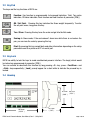
The pin layout of the
24 VDC connector of
BX18
( Top view )
24V 0V
Figure 3-2 - The pin layout of 24VDC connector
Warning: Before interfering the instrument, turn off the power and wait at least for 30 seconds.
Warning: Connect the grounding
pin to the reference ground.
Step 4. Energize the instrument
Check the mechanical installation, grounding, load cell connection and power supply connection to
be sure the correct electrical installation before energizing the instrument. If before steps are done
properly energize the instrument.
Step 5. Set the calibration switch to programming and calibration
Warning : If the scale is sealed before, call the authorized person before interfaring the scale.
If any, a set-up DIP switch is located under the blind cover as shown in the figure below and its
position should be “ON” ( downward ) to change the metrological related parameters including
calibration. If there is not set-up DIP switch on the instrument for industrial usage, its position is
always ON.
DIP Switch Description
1
Calib SW
2
Reserve
Figure 3-3 - The location of calibration DIP switch
BX18 Smart Process Indicator, User Manual, Rev. 1.1, May 2013
Page 8 of 32

















![Manual Mster disco 96 Español version 2[...]](http://vs1.manualzilla.com/store/data/006231891_1-1cde1092b79f743b833e51a9d2459349-150x150.png)