1
LATIN TECH
WWW.LT-AUTOMATION.COM
Section 1: Operating Procedure
1.
2.
3.
4.
5.
6.
Introduction
Programming
Simulation
Downloading Ladder Logic Program
Errors and Problems
Monitoring PLC Operation
A. Capturing the I/O logic state
B. On-Line Monitoring & Control
C. Ladder Monitoring
7. Uploading Ladder Program from PLC
1-1
1-1
1-2
1-2
1-3
1-4
1-4
1-5
1-6
1-7
Section 2: Host Communication
1. Point-to-point System
2. Multi-point Communication System
2.1 Networking with RS485
2.2 Command/Response Format
- Calculation of FCS
- FCS calculation program example
2.3 Communication Procedure
- Framing Errors
- Command Errors
- Sample Program
3. Using Network TRiLOGI
4. Troubleshooting RS485 Network
2-1
2-3
2-3
2-5
2-5
2-6
2-7
2-8
2-8
2-8
2-9
2-10
Section 3: Command/Response Format
1. Device ID Read
2. Device ID Write
3. Read All Inputs
4. Read Input Channels
5. Read All Outputs
6. Read Output Channels
7. Read All Relays
8. Read Relay Channels
9. Read All Timer Contacts
10. Read Timer Contacts
11. Read All Counter Contacts
12. Read Counter Contacts
13. Read All Timer Present Values
3-1
3-1
3-2
3-3
3-3
3-4
3-4
3-5
3-6
3-6
3-7
3-7
3-8
5209 NW 74 AVE. SUITE 202 MIAMI, FL. 33166 USA 1-888-832-7568 Toll free 305-207-0076 Tel 1-775-637-6825 Fax
LATIN TECH
WWW.LT-AUTOMATION.COM
14. Read Timer Present Value
15. Read All Counter Present Values
16. Read Counter Present Values
17. Write Inputs
18. Write Outputs
19. Write Relay Channel
20. Write Timer Present Value
21. Write Counter Present Value
22. Baud Rate Write
23. Baud Rate Read
24. Halt PLC Operation
25. Resume PLC Operation
26. Host Communication Program Examples
27. Applications of Host Communication Capabilities
3-8
3-8
3-9
3-9
3-10
3-10
3-10
3-11
3-11
3-12
3-12
3-13
3-13
i) Combining ladder logic program and host computer
3-14
processing
ii) Using the T20H as a remote 24V I/O interface
3-15
iii) I/O sharing: host computer utilizing the I/Os not used by 3-15
ladder logic program
Operating Procedure
1. Introduction
The H-series PLC is a family of small, low cost, single-board Programmable Logic Controllers
(PLCs). Presently, the series spans from the T20H with 12 inputs, 8 outputs to the T64H with 40
inputs and 24 outputs. Members of the H-series controller family differ mainly in the number of
I/Os (inputs/outputs), and the type of I/Os they carry (relay or transistor outputs, PNP or NPN
types, opto-isolator inputs or high voltage inputs, etc). Since each different PLC model has
different wiring requirements, please refer to their respective Installation Guide on the wiring
methods and installation details. The number of I/Os, timers, counters, internal relays as well as
the maximum allowable program steps are also stated in the Installation Guide.
This manual is to be used with all the current and future H-series PLCs. Presently they include the
T20H-npn, T28H-Relay, T44H-pnp, T44H-npn and the T64H-Relay. New models may be
introduced as and when determined by market demand. The following table summarizes the
number of I/Os, timers, counters and internal relays for each existing model:
5209 NW 74 AVE. SUITE 202 MIAMI, FL. 33166 USA 1-888-832-7568 Toll free 305-207-0076 Tel 1-775-637-6825 Fax
LATIN TECH
No. of
WWW.LT-AUTOMATION.COM
Inputs
Outputs
Internal
Relays
Timers
Counters
Maximum
Program Steps
12
16
28
40
8
12
16
24
128
128
128
256
20
20
20
40
20
20
20
40
400
400
400
800
Model
T20H-npn
T28H-Relay
T44H-npn/pnp
T64H-Relay
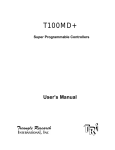
Position of Locating Pin for H-series PLCs
A
A1
B
A2
Model
T20H-npn
T44H-npn
T28H-Relay
T40H-Relay
T64H-Relay
A(mm)
78.11
139.7
159.39
186.06
182.25
B(mm)
83.19
106.68
87.00
93.98
113.67
A1(mm)
83.82
-
A2(mm)
83.82
-
2. Programming
The H-series controller is programmed using the software TRiLOGI Version 3.1
(or higher) which runs on an IBM compatible PC. This is a full-screen ladder logic
editor, compiler and simulator software. TRiLOGI is a standalone software
package which provides a powerful programming and debugging environment for
ladder logic programming. Please refer to TRiLOGI's User Manual for details.
TRiLOGI is designed to program a larger number of I/Os, relays, timers and
counters than are available on most of the models. Use no more than what are
available on the controller (as described in the last section) for your programming
purposes or else the program may not be transferred to the controller.
3. Simulation
A powerful feature unique to the TRiLOGI development environment is the builtin simulator. With the simulator, you can interact with your program by simulating
the input conditions using only a keyboard and examine the status and present
5209 NW 74 AVE. SUITE 202 MIAMI, FL. 33166 USA 1-888-832-7568 Toll free 305-207-0076 Tel 1-775-637-6825 Fax
LATIN TECH
WWW.LT-AUTOMATION.COM
values of the outputs, relays, timers and counters on screen immediately. The
simulator does not require any physical connection to the target PLC, and thus it
offers the most effective way of testing and debugging your ladder logic program
prior to installation of the hardware. No other low-cost PLC development
environment to-date offers an on-screen simulator to ease the programming chore.
Programming and debugging time can be greatly reduced if you make good use of
the simulator feature to eliminate as many logic errors as possible before testing
the program on the actual hardware. It also helps to reduce the chances of costly
damage to the machine due to programming errors.
4. Downloading the Ladder Logic Program
Once you are satisfied with the TRiLOGI-simulated scenarios, return to the ladder
logic editor by pressing the <ESC> key. To transfer the ladder program to the PLC,
first connect the PC to either the RS232 or RS485 port of the PLC and turn on its
power supply. You may either press <Ctrl-T> on the keyboard or open the
"Controller" pull-down menu and select item "Program Transfer". TRiLOGI will
query the target controller to obtain its maximum number of inputs, outputs, etc.
TRiLOGI will recompile the ladder program to ensure that these limits are not
violated. When compilation is successful, the compiled code will be transferred to
the H-series PLC in just a few seconds.
After the program has been successfully transferred, you will be prompted to
indicate if you wish to clear all outputs, relays, timers and counters to "OFF". A
successfully transferred program will be executed at once.
If errors occur during program downloading and the communication is aborted, the
CPU will not execute the partially transmitted program to forestall undesirable
consequences. If everything goes well, you may return to the editor by pressing
any key.
If you encounter a "Communication Error" in the program transfer procedure, the
following are some possible causes:
1)
2)
3)
4)
The PLC is not connected to the cable.
The host computer COM port is not connected to the cable.
Wrong COM port number is specified. Try another one.
Faulty serial port of host computer: test if the serial port is working using a
mouse or a serial printer. Try with another PC if possible.
5) Faulty serial cable, try another one.
6) Power to PLC is not turned on or an inadequate power supply has been used.
There was one case where a faulty switching power supply generated
excessive electrical noise which disrupted proper communication between
the PLC and the PC. This fault was not apparent as the power supply did
5209 NW 74 AVE. SUITE 202 MIAMI, FL. 33166 USA 1-888-832-7568 Toll free 305-207-0076 Tel 1-775-637-6825 Fax
LATIN TECH
WWW.LT-AUTOMATION.COM
give accurate voltage reading when its output was measured using a digital
multi-meter. Try with another power supply if available.
7) Faulty communcation hardware on the PLC - call your local dealer for
assistance.
5. Errors and Problems
Any error in the source file detected during compilation will abort the program
transfer process immediately. The cause of the first error will be reported on
screen, although you should never encounter this problem if you did simulate the
program successfully in TRiLOGI. This is because TRiLOGI's ease of
programming reduces the possibility of errors to a minimum, and any error would
have been detected and rectified before any simulation can take place.
The EEPROM in the PLC allows a ladder logic program to contain up to a certain
maximum number of steps. (Check the Installation Guide for the maximum number
of program steps for your PLC model) Each contact and ordinary output coil takes
1 step, while the output coils of timers and counters occupy 2 steps each. Functions
such as ANDLD, ORLD (these two instructions are implicit in the ladder diagram)
ILock, ILoff and MaCLR take only half a step.
If your ladder logic program used up more than the maximum available steps, the
compiler will record this as an error and the downloading process will be aborted.
If this happens, you need to simplify your program to optimize the use of program
memory.
6. Monitoring PLC Operations
A. Capturing the I/O logic state
On the ladder logic editor screen or simulator screen of TRiLOGI, the current
logic states and present values of the PLC's inputs, outputs, relays, timers and
counters can be captured by simply pressing the function key <F8>. The
captured I/O logic states and present values of timers and counters will be
updated immediately on the screen. If a contact or a coil is active (logic '1'), its
label name will be highlighted in the ladder diagram and this enables the
programmers to easily identify the trouble-causing elements that affect the
desired logic outcomes.
After capturing the actual logic states of PLC, you may step through the
operation sequences by simulating them on the PC screen. You can also change
the ladder logic program and test the new code using the simulator, all without
affecting the actual machine operation. This is perhaps the greatest advantage
of the TRiLOGI program development environment -- enabling the programmer
to test his code instantly without worrying that something may break as a result.
5209 NW 74 AVE. SUITE 202 MIAMI, FL. 33166 USA 1-888-832-7568 Toll free 305-207-0076 Tel 1-775-637-6825 Fax
LATIN TECH
WWW.LT-AUTOMATION.COM
When the simulation yields satisfactory results, simply download the new
program to the controller by pressing <Ctrl-T> and the actual machine will run
in the predictable manner as indicated by the simulation.
Note: TRiLOGI's simulator will be suspended temporarily when the <F8> key is pressed.
This is to preserve the current contents of the timer registers so that the programmer
has time to examine them. To continue simulation, simply press the <P> key to release
the simulator from the "System Paused" mode.
B. On-Line Monitoring & Control
With TRiLOGI Version 3.1 or higher you have direct control of the PLC
operation from within the program. You can enter this mode by selecting the
"On-Line Mon/Control" command from the "Controller" main menu, or by
pressing the "Ctrl-M" hotkey. A screen similar to the simulator will appear with
the flashing title "On-Line Monitoring & Control" along the top of the screen.
The following are what may be done in this mode:
Monitoring
TRiLOGI continuously monitors the I/O logic states and present values of the
timers and counters of the controller and displays them on screen. You may
scroll up and down any I/O window using the cursor keys and the <PgUp> and
<PgDn> keys to examine I/Os that are outside the present page. A highlight bar
will appear when an I/O window is selected (its border is highlighted). The
location of this highlight bar indicates the particular I/O bit selected.
Force Setting/Resetting I/O Bits
If you hit <Enter> key while in this mode, the selected I/O bit of the controller
will be forced to toggle (change state) by TRiLOGI using host link commands.
If the selected bit is a physical input bit or has been assigned to an output coil
controlled by the ladder diagram, it will only be toggled for one-scan time.
After that the controller will refresh its input/output according to the actual
states of the physical inputs and outputs determined by the outcome of the
ladder program. This is sometimes useful during program testing or debugging
for temporarily overriding an I/O that does not respond as predicted.
Suspending PLC's Ladder Program
You can suspend the operation of the controller at any time by pressing the <P>
key. A warning message will appear and a flashing sign "System Paused" will
be displayed on the upper right hand corner. When the controller is suspended,
its ladder program will not be executed until it is resumed by pressing the <P>
key again. At this time you can force set or reset any relay or output bits. This is
convenient during programming or debugging as you can control the output
driver to bring any physical component to any desired locations effortlessly.
5209 NW 74 AVE. SUITE 202 MIAMI, FL. 33166 USA 1-888-832-7568 Toll free 305-207-0076 Tel 1-775-637-6825 Fax
LATIN TECH
WWW.LT-AUTOMATION.COM
C. Ladder Monitoring
You can also monitor the logic states of I/Os directly on the ladder diagram by
selecting the "Ladder Monitoring" commands in the "Controller" or by pressing
<Ctrl-T> . When you enter the "Ladder Monitoring" mode TRiLOGI will
continuously monitor the controller's I/O logic states and display any "ON" I/O
bit with highlighted label names on the ladder diagram. You can still scroll
up/down the ladder programs while performing ladder monitoring, using the
cursor keys, <PgUP> <PgDn> and <Ctrl-PgUp> and <Ctrl-PgDn>, etc.
However, you may not use the left/right cursor keys to observe logic states of
I/Os outside the current screen.
Note: On-line control/monitoring and Ladder monitoring are achieved by
continuously sending host link commands to the PLC and analyzing the
response strings immediately in order to update the I/O tables. Since the
controller must spare some time to process the host-link commands, the
overall scan time will slow down during on-line or ladder monitoring.
Take precaution that programs which require fast scan-time, such as
capturing encoder pulses or counters fed by the 0.01s and 0.02s clock
sources, may lose some accuracy.
5209 NW 74 AVE. SUITE 202 MIAMI, FL. 33166 USA 1-888-832-7568 Toll free 305-207-0076 Tel 1-775-637-6825 Fax
LATIN TECH
WWW.LT-AUTOMATION.COM
7. Uploading Ladder Program from PLC
If you are using TRiLOGI Version 3.2 or higher, it is possible to retrieve the
compiled code from the PLC's EEPROM and re-construct them into ladder
circuits. To perform uploading, open the "Controller" pull down menu and select
the new item "Target Access". A pop-up menu with two items "Set Password" and
"Retrieve PLC's Ladder" will appear. Select "Retrieve PLC's Ladder" and you will
be prompted to confirm your wish to obtain the ladder program from the PLC.
Note that since the I/O label names and comments defined in the original program
were never saved in the PLC, the re-constructed ladder diagram can only make use
of the I/O labels defined in the currently opened file. Since the uploaded program
replaces all the existing ladder circuits, make sure that you keep a backup copy if
you do not wish to lose the contents of the currently opened file.
If an I/O used in the PLC's code is not defined in the current file, the program will
prompt you to enter the label name. You can use the default name by pressing the
<ESC> key. A default name defines an input as "In1", "In2"..., output as
"Out1","Out2"... etc.
Password Security
A password of 1 to 6 characters may be defined by the users by selecting the "Set
Password" item from the "Target Access" menu. Once defined, the target PLC
program may not be uploaded unless the same password is entered.
If you wish to change the password, select the "Set Password" item and you will
be prompted to enter the original password. If the correct password is entered, you
will be prompted to enter the new password. If you simply press the <Enter> key
without entering any character, the original password will be cleared and the user
may freely upload the PLC code.
Note: The password will also be cleared each time you perform a "Program
Transfer" which will overwrite the existing ladder program.
Host Communication
While a H-series programmable logic controller is running, a host computer may send
commands in the form of ASCII strings to the controller to read or write to the inputs,
outputs, relays, timers and counters. These ASCII commands are known as the "host-link
5209 NW 74 AVE. SUITE 202 MIAMI, FL. 33166 USA 1-888-832-7568 Toll free 305-207-0076 Tel 1-775-637-6825 Fax
LATIN TECH
WWW.LT-AUTOMATION.COM
commands" and are to be serially transmitted (via RS232C or RS485 port) to and from
the controller. The standard serial port settings for communication are: 9600 baud, 8 data
bit, 1 stop bit, no parity. Some models of PLC allow the serial port to be configured to
another baud rate using the "BW" command described in Section 3.
All H-series PLCs support both point-to-point (one-to-one) and multi-point (one-tomany) communication protocols and hardware. Each protocol has a different command
structure as described below:
1. Point-to-point Communication
In a point-to-point communication system, the host computer's RS232C serial port is
connected to the PLC. At any one time, only one controller may be connected to the
host computer. The host-link commands do not need to specify any controller ID code
and are therefore of simpler format, as shown below:
Command/Response Block Format (Point to Point)
x
Header
x
....
Data
.... ....
*
Terminator
Each command block starts with a two-byte ASCII character header, followed by a
number of ASCII data and ends with a terminator which comprises an '*' character
and a carriage return (ASCII value = 1310). The purpose of the command is denoted
by the header, e.g. RI for Read Input, WO for Write Output, etc. The data are usually
the hexadecimal representation of numeric data. Each byte of binary data is
represented by two ASCII characters (00 to FF).
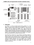
To begin a communication session, the host computer must first send one byte of
ASCII character: Ctrl-E (=05Hex) via its serial port to the controller. This informs
the controller that the host computer wishes to send a (point-to-point) host-link
command to it. Thereafter, the host computer must wait to receive an echo of the
Ctrl-E character from the controller. Reception of the echoed Ctrl-E character
indicates that the controller is ready to respond to the command from the host
computer. At this moment, the host computer must immediately send the command
block to the controller and then wait to receive the response block from the controller.
The entire communication session is depicted in Figure 2-1.
5209 NW 74 AVE. SUITE 202 MIAMI, FL. 33166 USA 1-888-832-7568 Toll free 305-207-0076 Tel 1-775-637-6825 Fax
LATIN TECH
WWW.LT-AUTOMATION.COM
Host Computer
The H-series PLC
Send Ctrl-E
(05H) and wait
for echo
Ready to process
command: return
Ctrl-E (05H)
Send Command
string to controller
Wait for response
Execute command.
Return Response
string to host
Accept Response
Check for errors
Figure 2-1
After the controller has received the command, it will send a response block back to
the host computer and this completes the communication session. If the command is
accepted by the controller, the response block will start with the same header as the
command, followed by whatever information that is requested by the command and
the terminator.
If an unknown command is received or if the command is illegal (such as access to an
unavailable output or relay channel), the following error response will be received:
Error Response Format
E R *
The host computer program should always check the returned response for
possibilities of errors in the command and take necessary actions.
2. Multipoint Communication system
5209 NW 74 AVE. SUITE 202 MIAMI, FL. 33166 USA 1-888-832-7568 Toll free 305-207-0076 Tel 1-775-637-6825 Fax
LATIN TECH
WWW.LT-AUTOMATION.COM
In this system, one host computer may be connected to multiple H-series controllers
on a RS485 network. The T28H, T44H and T64H controllers all have built-in RS485
ports. In the case of T20H a RS485 port is available on the expansion board TXP24,
or available as an optional unit. T28H and T44H have only one serial port each,
which can be connected either to the RS232C or the RS485, depending on the setting
of their respective DIP switch SW1-2 (please refer to their respective Installation
Guide).
In the case of T64H-Relay, two independent serial ports are available: one is
connected to the RS232C while the other is connected to the RS485 port. Both serial
ports may be accessed simultaneously by two computers, provided that only point-topoint commands are sent via the RS232C port and only multi-point commands are
sent via the RS485 port.
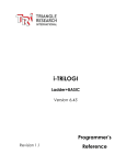
2.1 Networking with RS485
The built-in RS-485 interface allows the H-series controllers to be networked to
a host computer using very low cost twisted-pair cables. RS-485 allows up to
32 controllers (including the host computer node) to be networked together, at
baud rates up to 38,400 bps. The twisted-pair cable goes from node to node in a
daisy chain fashion and should be terminated by 120 ohm resistors at each end
as shown below.
+5V
Terminating
resistor
Twisted-pair RS485 network cable
Terminating
1K
+ resistor
120W
_
120 Ω
+
_
Host Computer with
RS-485 Interface
+
_
T28H
RS485
+
_
T44H
RS485
+
_ 1K
0V
T64H
RS485
Figure 2-2
Note that the two wires are not interchangeable so they must be wired the same
way to each controller. The maximum wire length should not be more than 1000
metres. RS-485 uses balanced or differential drivers and receivers, this means
that the logic state of the transmitted signal depends on the differential voltage
between the two wires and not on the voltage with respect to a common ground.
RS485 is a half-duplex network, i.e. the same two wires are used for both
transmission of the command and reception of the response. Of course, at any
one time, only one transmitter may be active. The H-series controllers
implement master/slave network protocols. The network requires a master
controller which is typically a microcomputer equipped with a RS485 interface.
5209 NW 74 AVE. SUITE 202 MIAMI, FL. 33166 USA 1-888-832-7568 Toll free 305-207-0076 Tel 1-775-637-6825 Fax
LATIN TECH
WWW.LT-AUTOMATION.COM
In the case of an IBMPC or AT, you can purchase a RS-485 adapter card or a
RS232C-to-RS485 converter and connect it to the RS232C serial port.
All H-series controllers are slave devices. They do not initiate commands to
each other or to the master. Only the master can issue commands to the slave
controllers. To transmit a command, the master controller must first enable its
RS-485 transmitter and send a multi-point command to the network of
controllers (please refer to Section 3 for explanation on the command formats
and protocols for multi-point commands). After the last stop bit has been sent,
the master controller must relinquish the RS485 bus by disabling its RS485
transmitter and enabling its receiver. At this point the master will wait for a
response from the slave controller that is being addressed.
Since the command contains the ID of the target controller, only the controller
with the correct ID would respond to the command by sending back a response
string. For the network to function properly, it is obvious that no two nodes can
have the same ID. Refer to Section 3 under the "IW" command on how to set
the device ID. Also, all nodes must be configured to the same baud rate.
As there will be times when no transmitters are active (which leaves the wires in
"floating" state), it is a good practice to ensure that the RS-485 receivers will
indicate to the CPUs that there is no data to receive. In order to do this, we
should hold the twisted pair in the logic '1' state by applying a differential bias
to the lines using a pair of 1KΩ resistors connected to a +5V and 0V supply as
shown in Figure 2-2. Otherwise, random noise on the pair could be falsely
interpreted as data. Also, care should be taken to ensure that the power supplies
for all the controllers are properly isolated from one another and from the main
so that no large ground potential differences exist between any controllers on the
network.
2.2 Command/Response Block Format (Multipoint)
@ n
n
Device ID
x
Header
x
.... .... ....
Data
x
FCS
x
*
Terminator
Each command block starts with the character "@" and two-byte hexadecimal
representation of the controller's ID (00 to FF), and ends with a two-byte "Frame
Check Sequence" (FCS) and the terminator. FCS is provided for detecting
communication errors in the serial bit-stream. If desired, the command block
may omit calculating the FCS simply by putting the characters "00" in place of
the FCS.
5209 NW 74 AVE. SUITE 202 MIAMI, FL. 33166 USA 1-888-832-7568 Toll free 305-207-0076 Tel 1-775-637-6825 Fax
LATIN TECH
WWW.LT-AUTOMATION.COM
Calculation of FCS
The FCS is 8-bit data represented by two ASCII characters (00 to FF). It is a
result of Exclusive OR sequentially performed on each character in the block,
starting from @ in the device number to the last character in the data. An
example is as follow:
@ 0
4
Device ID
@
0
4
R
I
A
L
R
I
Header
A
L
Data
5
2
*
FCS
0100 0000
XOR
0011 0000
XOR
0011 0100
XOR
0101 0010
XOR
0100 1001
XOR
0100 0001
XOR
0100 1100
0101 0010
= 5216
Value 5216 is then converted to ASCII characters '5' (0011 0101) and '2' (0011
0010) and placed in the FCS field.
FCS calculation program example
The following C function will compute and return the FCS for the "string"
passed to it.
unsigned char compute_FCS(unsigned char *string)
{
unsigned char result;
result = *string++;
/*first byte of string*/
while (*string)
result ^= *string++; /* XOR operation */
return (result);
}
5209 NW 74 AVE. SUITE 202 MIAMI, FL. 33166 USA 1-888-832-7568 Toll free 305-207-0076 Tel 1-775-637-6825 Fax
LATIN TECH
WWW.LT-AUTOMATION.COM
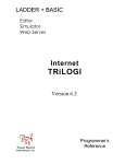
Host
Computer
RS232C
RS232 to RS485
converter
Shielded Twisted-pair RS-485 bus
H series PLC
H series PLC
120 Ohm
terminating
resistor
H series PLC
Figure 2-3 - A Multi-drop RS485 network
2.3 Communication Procedure
Unlike the point-to-point communication protocol, the host computer must NOT
send the CTRL-E character before sending the command block. After the host
computer has sent out the multi-point host link command block, only the
controller with the correct device ID will respond. Hence it is essential to ensure
that every controller on the RS485 network assumes a different ID. Otherwise
contention may occur (i.e. two controllers simultaneously sending data on the
receiver bus, resulting in garbage data being received by the host). On the other
hand, if none of the controller IDs match that specified in the command block,
then the host computer will receive no response at all.
The PLC automatically recognizes the type of command protocols (point-topoint or multi-point) sent by the host computer and it will respond accordingly.
If a multi-point command is accepted by the controller, the response block will
start with a character '@', followed by its device ID and the same header as the
command, then the data requested by the command, a response block FCS and
the terminator.
Framing Errors
When the controller receives a multi-point host link command block, it
computes the FCS of the command and compares it with the FCS field received
5209 NW 74 AVE. SUITE 202 MIAMI, FL. 33166 USA 1-888-832-7568 Toll free 305-207-0076 Tel 1-775-637-6825 Fax
LATIN TECH
WWW.LT-AUTOMATION.COM
in the command block. If the two do not match, then a "framing error" has
occurred. The controller will send the following Framing Error Response to the
host:
Framing Error Response Block (Multi-point only)
x
@ x
F
Device ID
E
x
Header
x
*
FCS
Terminator
Command Errors
If an unknown command is received or if the command is illegal (such as an
attempt access an unavailable output channel), the following error response
will be received:
Error Response Format
@ x
x
Device ID
E
R
Header
x
FCS
x
*
Terminator
The host computer program should always check the returned response for
possibilities of errors in the command and take necessary action.
Sample Program
To help you get started, a sample networking program "HOST485.C" for the
IBMPC has been written in Turbo C and is provided in the TRiLOGI Version
3.1/3.2 distribution diskette. This program works with an RS232-to-RS485
adapter attached to either COM1: or COM2: port of the PC. In this adapter, the
direction of the RS485 transceiver is controlled by the /RTS line of the serial
port. The RS485 transmitter is enabled only when the /RTS line is active,
otherwise the transmitter is disabled and the receiver is enabled. The logic states
of the /RTS line is determined by bit 1 of the "Modem control" register (at I/O
address 3FC for COM1: and 2FC for COM2:) of the 8250 UART used in the
PC serial adapter. You will need to modify some or all the following hardwaredependent functions if your RS485 adapter uses different UART and/or different
method of controlling the transceiver's direction:
transmit485(), receive485(), serial_out(), serial_status()
and serial_in().
5209 NW 74 AVE. SUITE 202 MIAMI, FL. 33166 USA 1-888-832-7568 Toll free 305-207-0076 Tel 1-775-637-6825 Fax
LATIN TECH
WWW.LT-AUTOMATION.COM
3. USING NETWORK TRiLOGI
If you have connected the RS485 interface of a few H-series PLCs into a multidrop network, you may download program or monitor the operation of any PLC
from a single host computer connected to the network. Note that the host
computer's RS485 adapter must be approved by Triangle Research to be compatible
with the NETWORK-TRiLOGI.
The network version of TRiLOGI Version 3.2 is available as a separate file:
"TL32NET.EXE" This program is almost identical to TL32.EXE, the exception
being an additional command item "Select Controller
Ctrl-I" in the
"Controller" main menu. For this program to function properly, each PLC on the
network must assume a unique ID. Use the "Host Link Command" in the "Controller"
menu and the command "BWxx" (xx = 00 to FF is the controller ID) to set the
ID of each controller separately before connecting them to the network. When
running the "TL32NET.EXE" program you can easily select any specific PLC to
work with by specifying its ID.
After entering the device ID, Network TRiLOGI will automatically query the PLC of
that particular ID for its source file name. It then searches the current directory of the
PC's disk drive for a matching file. If found, it will prompt the user to confirm
whether he/she wishes to open the source file. The selected controller is then
available for program-downloading or On-line/Ladder monitoring as per the normal
TRiLOGI operation. To switch to another PLC, simply press <Ctrl-I> and enter
another ID. This program offers a quick way to test a new RS485 network.
If a communication errors occur, check to see if the PLC's ID has been properly
defined. Next check for loose or incorrect wiring to the RS485 terminal. In the case
of the T28H and T44H PLCs, ensure that the serial port selection DIP switch has
been properly set. The 8-pin DIP IC - SN75176 provides the RS485 interface and it
may be necessary to replace it if it is damaged during installation as a result of over
voltage/current or prolonged short-circuit of its two terminals, etc.
4. Trouble-Shooting RS485 Network
a) Single faulty device
If a single device on the RS485 network becomes inaccessible, problems can be
isolated to this particular device. Check out for loose or broken wiring or wrong
DIP switch settings. Also double check the device ID using the host link
command "IR*" sent via the RS232C port of the PLC. If all attempts fail, either
replace the entire PLC or the SN75176 chip which handle the RS485 interfacing
and try again.
5209 NW 74 AVE. SUITE 202 MIAMI, FL. 33166 USA 1-888-832-7568 Toll free 305-207-0076 Tel 1-775-637-6825 Fax
LATIN TECH
WWW.LT-AUTOMATION.COM
b) Multiple faulty devices
If all the PLCs are inaccessible by the host computer, it may possibly be due to a
faulty RS232C-to-RS485 converter at the PC, If this is the case, disconnect the
RS485 converter from the network and check it using a single PLC. Also check to
ensure that the converter has been properly configured with the correct DIPswitch settings. Replace the converter if it is confirmed to be faulty. Next check
the wire from the converter to the begining of the network. A broken wire here
can lead to the failure of the entire network.
Since a RS485 network links many PLCs together electrically and in a daisy chain
fashion, problems occurring along the RS485 network sometimes affect the
operation of the entire network. For example, a broken wire at the terminal of one
node may mean that all the PLCs connected after this node become inaccessible
by the master. If the RS485 interface of one of the PLCs has short-circuited
because of component failure, then the entire network goes down with it too. This
is because no other nodes is able to assert proper signals on the two wires that are
also common to the shorted device.
Hence when trouble-shooting a faulty RS485 network, it may be necessary to isolate
all the PLCs from the network, then connect one PLC at a time back to the network,
starting from the node nearest to the host computer. Use network TRiLOGI to check
communication with each PLC until the faulty
Command/Response Format
This section describes the detailed formats of the command and response blocks for
the entire H-series PLC host-link commands. Only the formats for the point-to-point
communication system are presented, but all these commands are available to the
multi-point system as well. To use a command for multi-point system, simply add the
device ID (@nn) before the command header and the FCS at the end of the data (See
Section 2 for detailed description of multipoint communication command format).
Since different models of PLCs have different maximum number of inputs, outputs,
internal relays, timers and counters, attempts to send commands to an invalid address
will result in an error response from the controller. For commands that read ALL the
channels such as "RIAL", the response string will contain up to the maximum number
of channels available on that PLC. The maximum channel numbers stated in the
subsequent parts of this manual is based on the assumption that the PLC has 96
inputs, 64 outputs, 256 internal relays, 64 timers and 64 counters. The actual limits on
your PLC can be observed during the transfer of your TRiLOGI program into the
5209 NW 74 AVE. SUITE 202 MIAMI, FL. 33166 USA 1-888-832-7568 Toll free 305-207-0076 Tel 1-775-637-6825 Fax
LATIN TECH
WWW.LT-AUTOMATION.COM
controller. You should work with the actual limit of the PLC model you are using and
not what's stated in the following sections.
1. Device ID Read
Command Format
I
R
∗
Response Format
I
R
16
160
∗
Device ID (00 to FF)
The device ID is to be used for multi-point communication protocol where the host
computer can selectively communicate with any controller connected to a common
RS485 bus (see Section 2 for details). The ID has no effect for point-to-point
communication.
The device ID is stored in the PLC's EEPROM and therefore will remain with the
controller until it is next changed.
2. Device ID Write
Command Format
I
W
16
160
∗
Device ID (00 to FF)
Response Format
I
W
∗
3. Read All Inputs
Command Format
R
I
A
L
∗
Response Format
5209 NW 74 AVE. SUITE 202 MIAMI, FL. 33166 USA 1-888-832-7568 Toll free 305-207-0076 Tel 1-775-637-6825 Fax
LATIN TECH
R
I
WWW.LT-AUTOMATION.COM
16
160
16
CH0
160
CH1
....
....
16
......
160
∗
CH11
The data part of the response string contains the hexadecimal values of all the input
channels from channel #0 to the maximum channel#. The 8-bit inputs of each
channel is represented by two bytes ASCII text expression of its hexadecimal
value. For example: if inputs 1 to 3 are logic '0's, inputs 4 to 8 are logic '1's and all
other inputs are logic '0's, then CH0=1111 1000, which is represented as ASCII
characters 'F' and '8'.
Definition of Input Channels
The following table shows the input numbers as defined in TRiLOGI's Input entry
table corresponding to the input channel number.
Bit7
CH0:
CH1:
CH2:
CH3:
CH4:
CH5:
CH6:
CH7:
CH8:
CH9:
CH10:
CH11:
8
16
24
32
40
48
56
64
72
80
88
96
7
15
23
31
39
57
55
63
71
79
87
95
6
14
22
30
38
56
54
62
70
78
86
94
Input Numbers
5
4
13
12
21
20
29
28
37
36
45
44
53
52
61
60
69
68
77
76
85
84
93
92
Bit0
3
11
19
27
35
43
51
59
67
75
83
91
2
10
18
26
34
42
50
58
66
74
82
90
1
9
17
25
33
41
49
57
65
73
81
89
4. Read Input Channels
Command Format
R
I
n
n
∗
nn: CH0=00, CH1=01, .... CH11=0B
Response Format
R
I
16
160
∗
8-bit channel value (Hex)
5209 NW 74 AVE. SUITE 202 MIAMI, FL. 33166 USA 1-888-832-7568 Toll free 305-207-0076 Tel 1-775-637-6825 Fax
LATIN TECH
WWW.LT-AUTOMATION.COM
5. Read All Outputs
Command Format
R
O
A
L
∗
160
....
Response Format
R
O
16
....
CH0
16
160
∗
CH7
Definition of Output Channels
The following table shows the physical output number corresponding to the output
channels 0 and 1.
bit7 Output numbers bit0
CH0:
8
7
6
5
4
3
2
1
CH1:
16
15
14
13
12
11
10
9
CH2:
24
23
22
21
20
19
18
17
CH3:
32
31
30
29
28
27
26
25
CH4:
40
39
38
37
36
35
34
33
CH5:
48
57
56
45
44
43
42
41
CH6:
56
55
54
53
52
51
50
49
CH7:
64
63
62
61
60
59
58
57
6. Read Output Channels
Command Format
R
O
n
n
*
nn: CH0=00, CH1=01, CH7=07
Response Format
R
O
16
160
∗
8-bit channel value in Hex
5209 NW 74 AVE. SUITE 202 MIAMI, FL. 33166 USA 1-888-832-7568 Toll free 305-207-0076 Tel 1-775-637-6825 Fax
LATIN TECH
WWW.LT-AUTOMATION.COM
7. Read All Relays
Command Format
R
R
A
L
∗
160
16
Response Format
R
R
16
CH0
160
CH1
....
......
....
16
160
∗
CH31
Definition of Relay Channels
The table shows the relay numbers defined in TRiLOGI's Relay
their corresponding channel numbers.
bit7
Relay numbers
CH0:
8
7
6
5
4
3
2
CH1:
16
15
14
13
12
11
10
CH2:
24
23
22
21
20
19
18
CH3:
32
31
30
29
28
27
26
CH4:
40
39
38
37
36
35
34
CH5:
48
57
56
45
44
43
42
CH6:
56
55
54
53
52
51
50
CH7:
64
63
62
61
60
59
58
CH8:
72
71
70
69
68
67
66
CH9:
80
79
78
77
76
75
74
CH10:
88
87
86
85
84
83
82
CH11:
96
95
94
93
92
91
90
CH12:
104
103
102
101
100
99
98
CH13:
112
111
110
109
108
107
106
CH14:
120
119
118
117
116
115
114
CH15:
128
127
126
125
124
123
122
CH16:
136
135
134
133
132
131
130
CH17:
144
143
142
141
140
139
138
CH18:
152
151
150
149
148
147
146
CH19:
160
159
158
157
156
155
154
CH20:
168
167
166
165
164
163
162
CH21:
176
175
174
173
172
171
170
CH22:
184
183
182
181
180
179
178
CH23:
192
191
190
189
188
187
186
CH24:
200
199
198
197
196
195
194
CH25:
208
207
206
205
204
203
202
entry table and
bit0
1
9
17
25
33
41
49
57
65
73
81
89
97
105
113
121
129
137
145
153
161
169
177
185
193
201
5209 NW 74 AVE. SUITE 202 MIAMI, FL. 33166 USA 1-888-832-7568 Toll free 305-207-0076 Tel 1-775-637-6825 Fax
LATIN TECH
CH26:
CH27:
CH28:
CH29:
CH30:
CH31:
WWW.LT-AUTOMATION.COM
216
224
232
240
248
256
215
223
231
239
247
255
214
222
230
238
246
254
213
221
229
237
245
253
212
220
228
236
244
252
211
219
227
235
243
251
210
218
226
234
242
250
209
217
225
233
241
249
8. Read Relay Channels
Command Format
R
R
n
n
∗
nn: CH0=00, CH1=01..... CH31=1F
Response Format
R
R
16
160
∗
8-bit channel value in Hex
9. Read All Timer Contacts
Command Format
R
T
A
L
∗
160
....
Response Format
R
T
16
CH0
....
16
160
∗
CH7
If an energized timer has timed-out, its contact (completion flag) will be read as a
"1", otherwise it is read as a "0".
Definition of Timer Channels
The following table shows the timer number defined in TRiLOGI's Timer entry
table and their corresponding channel numbers.
CH0:
CH1:
CH2:
bit7
8
16
24
7
15
23
Timer numbers
6
5
4
14
13
12
22
21
20
3
11
19
bit0
2
10
18
1
9
17
5209 NW 74 AVE. SUITE 202 MIAMI, FL. 33166 USA 1-888-832-7568 Toll free 305-207-0076 Tel 1-775-637-6825 Fax
LATIN TECH
CH3:
CH4:
CH5:
CH6:
CH7:
WWW.LT-AUTOMATION.COM
32
40
48
56
64
31
39
57
55
63
30
38
56
54
62
29
37
45
53
61
28
36
44
52
60
27
35
43
51
59
26
34
42
50
58
25
33
41
49
57
10. Read Timer Contacts
Command Format
R
T
n
n
∗
nn: CH0=00, CH1=01, CH2=02
Response Format
R
T
160
16
∗
8-bit channel value in Hex
11. Read All Counter Contacts
Command Format
R
C
A
L
∗
160
....
Response Format
R
C
16
....
16
CH0
160
∗
CH7
If a counter has counted down to zero, its contact will be read as a "1", otherwise
it is read as a "0".
Definition of Counter Channels
The following table shows the counter numbers defined in TRiLOGI's Counter
entry table and their corresponding channel numbers.
CH0:
CH1:
CH2:
CH3:
8
16
24
32
7
15
23
31
6
14
22
30
5
13
21
29
4
12
20
28
3
11
19
27
2
10
18
26
1
9
17
25
5209 NW 74 AVE. SUITE 202 MIAMI, FL. 33166 USA 1-888-832-7568 Toll free 305-207-0076 Tel 1-775-637-6825 Fax
LATIN TECH
CH4:
CH5:
CH6:
CH7:
WWW.LT-AUTOMATION.COM
40
48
56
64
39
57
55
63
38
56
54
62
37
45
53
61
36
44
52
60
35
43
51
59
34
42
50
58
33
41
49
57
12. Read Counter Contacts
Command Format
R
C
n
n
∗
nn: CH0=00, CH1=01, CH2=02
Response Format
R
C
16
160
∗
8-bit channel value in Hex
13. Read All Timer Present Values
Command Format
R
M
A
L
∗
Response Format
R
M 103 102 101 100 ....
Timer 1
.... 103 102 101 100
.........
∗
Timer 64
The present values of all the timers are returned in decimal form as four- byte
ASCII text characters from 0000 to 9999.
14. Read Timer Present Value
Command Format
R
M
n
n
∗
nn: Timer1=00, ..... Timer16=0F.... Timer64=3F
5209 NW 74 AVE. SUITE 202 MIAMI, FL. 33166 USA 1-888-832-7568 Toll free 305-207-0076 Tel 1-775-637-6825 Fax
LATIN TECH
WWW.LT-AUTOMATION.COM
Response Format
M 103 102 101 100
R
∗
Timer present value in Decimal
15. Read All Counter Present Values
Command Format
R
U
A
L
*
Response Format
R
U
103 102 101 100 ....
Counter 1
.... 103 102 101 100
.........
*
Counter 64
The present values of all the counters are returned in decimal form as four byte
ASCII text characters from 0000 to 9999.
16. Read Counter Present Value
Command Format
R
U
n
n
*
nn: Counter1=00, ..... Counter16=0F.... Counter64=3F
Response Format
R
U
103 102 101 100
*
Counter present value in Decimal
17. Write Inputs
Command Format
W
I
n
n
16
160
*
5209 NW 74 AVE. SUITE 202 MIAMI, FL. 33166 USA 1-888-832-7568 Toll free 305-207-0076 Tel 1-775-637-6825 Fax
LATIN TECH
WWW.LT-AUTOMATION.COM
Channel #
(00 to 0B)
Data
Response Format
W
I
*
5209 NW 74 AVE. SUITE 202 MIAMI, FL. 33166 USA 1-888-832-7568 Toll free 305-207-0076 Tel 1-775-637-6825 Fax
LATIN TECH
WWW.LT-AUTOMATION.COM
18. Write Outputs
Command Format
W
O
n
n
16
Channel #
(00 to 08)
160
∗
Data
Response Format
W
O
∗
19. Write Relay Channel
Command Format
W
R
n
n
16
Channel #
(00 to 0F)
Response Format
W
R
160
∗
Data
∗
20. Write Timer Present Value
Command Format
W
M
n
n
103 102 101 100
∗
Timer1=00,
New timer PV
....
Timer64=3F (Hex)
Response Format
W
M
∗
5209 NW 74 AVE. SUITE 202 MIAMI, FL. 33166 USA 1-888-832-7568 Toll free 305-207-0076 Tel 1-775-637-6825 Fax
LATIN TECH
WWW.LT-AUTOMATION.COM
21. Write Counter Present Value
Command Format
W
U
n
n
103 102 101 100
∗
Counter1=00,
New PV
....
Counter64=3F (Hex)
Response Format
W
U
∗
22. Baud Rate Write
Command Format
B
W
16
160
∗
Baud Rate No. (00 to 06)
Response Format
B
W
∗
Some of the H-series PLC can be configured to communicate at baud rate of
between 1200 and 38,400 baud. The BW command is used to defined the desired
baud rate. Each Baud Rate No (00 to 06) corresponds to a particular baud rate, as
follow:
Baud Rate No.
0
1
2
3
4
5
6
Transmission Speed
1200 bps
2400 bps
4800 bps
9600 bps
19,200bps
31,500 bps
38,400 bps
The baud rate number is stored in the PLC's EEPROM until it is overwritten by
the "BW" command again.
5209 NW 74 AVE. SUITE 202 MIAMI, FL. 33166 USA 1-888-832-7568 Toll free 305-207-0076 Tel 1-775-637-6825 Fax
LATIN TECH
WWW.LT-AUTOMATION.COM
Note that for T20H, T28H and T44H controller which has only one serial port,
the new baud rate will only take effect if their respective DIP switch SW1-3 is set
to the "ON" position when the PLC is first turned ON. Otherwise, the PLC is
automatically configured to communicate at 9600 baud. If it is desirable to
temporarily use the standard 9600 baud rate, you may turn OFF DIP switch SW13 and then reset the processor.
For PLCs with two serial ports such as the T64H-Relay, the RS232C port is
always fixed to communicate at 9600 baud. The "BW" command defines the
baud rate setting for the RS485 port. This ensure that you can always
communicate with the PLC via the RS232C port, regardless of the baud rate
setting of the RS485 port.
23. Baud Rate Read
Command Format
B
R
∗
Response Format
B
R
16
160
∗
Baud Rate No. (00 to 06)
24. Halting the PLC
Command Format
C
2
∗
Response Format
C
2
∗
When the PLC receives this command, it temporarily halts the execution of the
PLC's ladder program. The PLC continues to process host link commands sent to it
until it receives a resume command.
25. Resume PLC Operation
Command Format
5209 NW 74 AVE. SUITE 202 MIAMI, FL. 33166 USA 1-888-832-7568 Toll free 305-207-0076 Tel 1-775-637-6825 Fax
LATIN TECH
C
1
WWW.LT-AUTOMATION.COM
∗
Response Format
C
1
∗
When the PLC receives this command, it will resume execution of the ladder
program if it has been halted previously by the "C2" command. Otherwise, this
command has no effect.
26. Host Communication Program Examples
Two sample programs, one written in Microsoft GWBASIC (HOSTCOMM.bas)
and the other written in Borland International's Turbo C (HOSTCOMM.C), are
provided in the TRiLOGI distribution diskette to help programmers get started.
Both programs essentially perform the same functions, as follows:
(a) Prompt user to enter the desired command block via the PC's keyboard.
(b) Initiate a communication session (for point-to-point protocol only) and send
the command string to the controller.
(c) Wait to receive the response block from PLC and display the response block
on the PC's screen.
These two programs incorporate all the codes needed to communicate
successfully with the T20/28/44H in either BASIC or C language using the
point-to-point protocol. Programmers can therefore build their applications using
either of the programs as building blocks.
For those who wish to experiment with the RS485 network, A program
"Host485.C" in Turbo C language has also been included. This program assumes
that an RS232-to-RS485 adapter is used such that the direction of
communication of the RS485 bus is controlled by the state of /RTS line of the
RS232C. This program accepts both point-to-point and multipoint commands
from the keyboard and automatically initiates the correct communication
protocol with the control. If your RS485 adapter works differently then you must
modify the functions "transmit485()" and "receive485()" to control the direction of
the half-duplex RS485 bus. Please refer to the technical manual of your RS485
adapter for details.
5209 NW 74 AVE. SUITE 202 MIAMI, FL. 33166 USA 1-888-832-7568 Toll free 305-207-0076 Tel 1-775-637-6825 Fax
LATIN TECH
WWW.LT-AUTOMATION.COM
Although written for RS485 bus, you can also experiment with this program
using PLC's RS232 interface, you would however not be able to link more than
one H-series PLC to the host PC in this case.
27. Applications of Host Communication Capabilities
The H-series PLC's host-link capability gives rise to a number of possibilities of
using the controller in tandem with a host computer for control jobs that require
a higher level of intelligence for decision making.
Since the host computer only needs one serial port to interface with the PLC, an
inexpensive laptop, palmtop or notebook computer can be used both as a
programming console as well as a high level decision maker for controlling the
target machine.
The following are some possibilities and suggestions for using the host
communication ability of the H-series controller:
i) Combining ladder logic program and host computer processing
Use ladder logic program to perform all the tedious, repetitive logic control
tasks which often pose headaches to high-level language programmers. If a
host computer decision is required to execute a certain logic sequence, then
use any internal relay as the triggering input. The high level language
program running on a host computer can then trigger the desired logic
sequence by turning on or off the corresponding relay.
The ladder logic program can use any of its outputs or relays as a flag to
indicate to the host processor that a certain logic state has been reached and
requires the host computer's attention. The host computer will periodically
monitor the corresponding flag(s) to make further program decisions.
5209 NW 74 AVE. SUITE 202 MIAMI, FL. 33166 USA 1-888-832-7568 Toll free 305-207-0076 Tel 1-775-637-6825 Fax
LATIN TECH
WWW.LT-AUTOMATION.COM
ii) Using the PLC as a remote I/O interface
If you transfer a blank program to the PLC, all the inputs and outputs can be
directly controlled by the host computer. The PLC thus effectively becomes
a slave I/O processor, accepting only commands from the host computer and
then reading from or writing to the corresponding input and output channels
as specified in the command. While this may be a waste of the logic
processing power of the CPU, it may be useful if the application needs the
host computer to directly control all the inputs and the outputs.
iii) I/O sharing: host computer utilizing the I/Os not used by ladder
logic program
The host computer may directly turn on or turn off any of the output points
which are not controlled by the ladder logic program (i.e. these outputs do
not appear as "coil symbol
------(
)" in TRiLOGI). Thus it is
possible for a host computer to make use of the unused inputs and outputs of
the PLC for its own control purposes without affecting the underlying ladder
logic program that is currently running.
Caution: If the host computer attempts to control an output that is already
used by the ladder logic program and a conflict in the output
logic state occurs, the output will change its state, but only
momentarily and will return to the value decided by the outcome
of the ladder logic program in the next scan time. This might
result in a short pulse of width less than 1 scan time being sent to
the output terminal.
If this is undesirable, then it is the responsibility of the host
computer programmer to prevent this from happening. Since the
host computer can only read or write to the controller in terms of
an 8-bit channel at a time, bit-masking technique is needed if a
channel of output is to be shared by the ladder logic program as
well as the host computer.
5209 NW 74 AVE. SUITE 202 MIAMI, FL. 33166 USA 1-888-832-7568 Toll free 305-207-0076 Tel 1-775-637-6825 Fax
LATIN TECH
WWW.LT-AUTOMATION.COM
Conditions of Sale and Product Warranty
Triangle Research International Pte Ltd (Singapore) and the Buyer
agree to the following terms and conditions of Sale and Purchase:
1. The H-series Ladder Logic Programmable Controllers which
includes T20H/T28H/T44H/T40H/T64H etc is guaranteed against
defects in materials or workmanship for a period of one year from
the date of registered purchase. Any unit which is found to be
defective will, at the discretion of Triangle Research, be repaired
or replaced.
2. Triangle Research will not be responsible for the repair or
replacement of any unit damaged by user modification,
negligence, abuse and mishandling, or improper installation.
3. Triangle Research is not responsible to the Buyer for any loss or
claim of special or consequential damages.
4. Products distributed, but not manufactured by Triangle Research,
carry the full original manufacturers warranty. Such products
include, but are not limited to: power supplies, sensors, I/O
modules, and battery backed RAM.
5. Triangle Research reserves the right to alter any feature or
specification at any time.
5209 NW 74 AVE. SUITE 202 MIAMI, FL. 33166 USA 1-888-832-7568 Toll free 305-207-0076 Tel 1-775-637-6825 Fax
LATIN TECH
WWW.LT-AUTOMATION.COM
Copyright Notice and Disclaimer
TRiLOGI Version 1.x, 2.x, and 3.x are trademarks and
copyrights (c) 1989 to 1996 of TRIANGLE RESEARCH
INTERNATIONAL PTE LTD.
All rights reserved. No parts of this manual may be
reproduced in any form without the express written
permission of TRIANGLE RESEARCH.
TRIANGLE RESEARCH makes no representations or
warranties with respect to the contents hereof. In addition,
information contained herein are subject to change without
notice. Every precaution has been taken in the preparation
of this manual. Nevertheless, TRIANGLE RESEARCH
assumes no responsibility for errors or omissions or any
damages resulting from the use of the information
contained in this publication.
IBM PC, XT and AT are trademarks of International
Business Machines Corp.
MSDOS is a trademark of Microsoft Inc.
5209 NW 74 AVE. SUITE 202 MIAMI, FL. 33166 USA 1-888-832-7568 Toll free 305-207-0076 Tel 1-775-637-6825 Fax