1
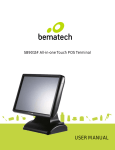
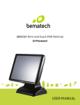
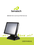
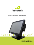
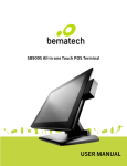
SB9015T All-in-one True-flat Touch POS Terminal USER MANUAL Table of Contents 1 Introduction ..........................................................................................2 1.1 1.2 Safety Information ........................................................................................ 2 Electromagnetic compatibility statement ................................................. 3 2 Overview ................................................................................................4 2.1 2.2 2.3 2.4 Appearances .................................................................................................... 4 Rear panel I/O connectors ............................................................................. 5 Rear View ......................................................................................................... 6 Control Panel ...................................................................................................7 3 Hardware Installation ..........................................................................8 3.1 3.2 3.3 3.4 3.5 3.6 Cable Routing.................................................................................................. 8 Installing MSR................................................................................................. 8 Installing Customer Display.......................................................................... 9 Installing Second LCD .................................................................................... 9 Replacing System Core ................................................................................. 10 Replacing Hard Disk Drive ............................................................................ 10 4 Setup and Driver Installation ............................................................ 11 4.1 4.2 4.3 4.4 Cash Drawer Port ............................................................................................11 Serial Ports Configurations .......................................................................... 12 Jumper settings ............................................................................................. 13 Motherboard BIOS settings ......................................................................... 15 5 Troubleshooting ................................................................................ 23 6 Specifications .................................................................................... 26 1 1 Introduction Thank you for purchasing the SB9015T all-in-one true-flat touch POS terminal. Bematech is committed to continuously improve product quality and provide better after-sales service. In order to take full advantage of our devices, we strongly recommend that you take the time to read this manual before diving into software solution. Note: Information in this manual may change without prior notice. 1.1 Safety Information Before plug in the product, please make sure the power you provide meets the power requirements (such as voltage, frequency); Make sure the ground terminal of the power outlet is working properly. To avoid electric shocks, disconnect the power cord from the electrical outlet before relocating the system. Lightning may damage this product. During lightning storms, unplug the network cable, power cable and any other connections. Turn off power before connecting any devices (except USB devices) to the terminal. Do not attempt to open the chassis. You may be hurt by electric shock. For service, call your place of purchase. Do not spill liquid on the terminal. Do not place any objects into the ventilation holes of this product. It may cause short-circuit of the internal components and cause a fire or electric shock. After the terminal is stored below temperature of 10 ° C, please place it in room temperature (10-35 ° C) in the original packing for at least two hours to allow the terminal to restore to room temperature before operation. This is to avoid condensation that might cause electrical damage. Keep the terminal clean, dry, and away from dust, moisture and direct sunlight. 2 Do not use harsh chemicals or strong cleaning solvents to clean the monitor screen. Wipe it clean with a soft terry cloth applied with a mild solution Do not share the same power outlet with high-power electrical appliances; keep distance from high level magnetic interference. Do not the use sharp pointed objects to work with the touch screen to avoid damage to the screen. When the following occurs: Liquid gets inside the POS terminal; Accidental physical damage; The power cord or plug is damaged; POS terminal produces a burning smell; Immediately disconnect the power supply, unplug the power cord, and contact a qualified service technician. 1.2 Electromagnetic compatibility statement FCC NOTICE This device complies with Part 15 of FCC Rules. Operations are subject to the following two conditions: (1) this device may not cause harmful interference, and (2) this device must accept any interference received, including interference that may cause undesired operation. EUROPEAN COMMUNITY (CE) MARK OF CONFORMITY This product is in conformity with the protection requirements of EU Council Directive 89/336/EEC on the approximation of the laws of the Member States relating to electromagnetic compatibility. Logic Controls cannot accept responsibility for any failure to satisfy the protection requirements resulting from a non-recommended modification of the product. This product has been tested and found to comply with the limits for Class A Information Technology Equipment according to CISPR 22 / European Standard EN 55022. The limits for Class A equipment were derived for commercial and industrial environments to provide reasonable protection against interference with licensed communication equipment. 3 2 Overview 2.1 Appearances 4 2.2 Rear panel I/O connectors At the rear panel of the SB9015T is a row of external I/O device connectors detailed as follows: System with D525 CPU System with i3 CPU 1 DC in DC in 2 HDD slot HDD slot 3 DC out (for 2nd LCD) DC out (for 2nd LCD) 4 Line out Line out 5 Cash drawer port Cash drawer port 6 COM5 COM4 7 USB port x 4 USB port x 4 8 LAN port LAN port 9 COM3 COM1 10 COM4 COM2 11 COM1 COM6 12 VGA port VGA port 13 PS/2 keyboard port PS/2 keyboard port 5 2.3 Rear View 1 VESA mounting holes 2 MSR module compartment 3 Speakers 4 VESA routing plate 5 Control panel 6 Display module compartment (for Customer display or 2nd LCD) 6 2.4 Control Panel 1 Brightness – Press the “Brightness –” button to decrease brightness. The setting will be saved 6 seconds after releasing the button. 2 Brightness + Press the “Brightness +” button to increase brightness. The setting will be saved 6 seconds after releasing the button. 3 USB ports Connect external peripherals such as a memory drive. 4 Power Button Press to turn the POS terminal on or off. The LED lights up blue when the power is on. Note: Press the “Brightness –” and “Brightness +” buttons at the same time to restore brightness to the factory default setting. 7 3 Hardware Installation 3.1 Cable Routing 3.2 Installing MSR 8 3.3 Installing Customer Display 3.4 Installing Second LCD 9 3.5 Replacing System Core 3.6 Replacing Hard Disk Drive 10 4 Setup and Driver Installation 4.1 Cash Drawer Port Pin-out Pin 1 2 3 6 1 System with D525 CPU Ground Drive output Sense input System with i3 CPU Ground Drive output 1 Sense input 4 +24V/+12V +24V/+12V 5 6 None Ground Drive output 2 Ground Operation System with D525 CPU COM port Baud rate COM6 1200 I/O address Open command Respond command 288h 01h 02h System with i3 CPU The Cash Drawer Controller use one I/O address to control the Cash Drawer. I/O address 48Ch Attribute Read/Write Size 8 bits 11 4.2 Serial Ports Configurations System with D525 CPU Connectors Function Pin 9 Power Support COM1 External, RS232 (DB9) +5V/+12V select by jumper COM2 Touch controller N/A COM3 External, RS232 (DB9) +5V/+12V select by jumper COM4 External, RS232 (DB9) +5V/+12V select by jumper COM5 External, RS232 (RJ45) +5V/+12V select by jumper COM6 Cash Drawer N/A COM7 Customer Display N/A Connectors Function Pin 9 Power Support COM1 External, RS232 (DB9) +5V/+12V select by jumper COM2 External, RS232 (DB9) +5V/+12V select by jumper COM3 Customer Display +5V only COM4 External, RS232 (RJ45) +5V/+12V select by jumper COM5 Touch controller +5V only COM6 External, RS232 (DB9) +5V/+12V select by jumper System with i3 CPU COM5 RJ45 Socket Pin Assignment RJ45-10 Pin No. Signal Name 1 NC, or +5/+12 VDC 2 GND 3 DTR 4 CTS 5 TX 6 RTS 7 RX 8 DSR 9 DCD 10 NC Note: Do not plug in or unplug any connector except USB devices when the power is on. The current loading for all COM ports should not exceed DC 5V/3A and DC 12V/2A. 12 4.3 Jumper settings System with D525 CPU JP2 - Cash drawer voltage setting 1-2 24V 2-3 12V JP4 - CMOS clear jumper 1-2 Normal 2-3 CMOS clear Default=24V Default=Normal JP5 - COM4 DB9 pin 9 voltage select 1-2 0V 3-4 +5V 5-6 +12V Default=0V JP6 - COM1 DB9 pin 9 voltage select 1-2 0V 3-4 +5V 5-6 +12V Default=0V JP7 - COM3 DB9 pin 9 voltage select 1-2 0V 3-4 +5V 5-6 +12V Default=0V JP8 - COM5 DB9 pin 9 voltage select 1-2 0V 3-4 +5V 5-6 +12V Default=0V System with i3 CPU JP3 - Clear CMOS Contents 1-2 Normal 2-3 Clear CMOS 13 Default=Normal JP6 - CN7 Cash Drawer Power Selection 1-2 +24V 2-3 +12V Default=+24V JP7 - CN1 USB Power Selection 1-2 +5VSB 2-3 Default=+5VSB +5V JP8 - CN4 USB Power Selection 1-2 +5VSB 2-3 Default=+5VSB +5V JP9 - COM4 RS232 pin 9 function select 1-2 RI 3-4 +5V 5-6 +12V Default=RI JP10 - COM6 RS232 pin 9 function select 1-2 RI 3-4 +5V 5-6 +12V Default=RI JP11 - COM2 RS232 pin 9 function select 1-2 RI 3-4 +5V 5-6 +12V Default=RI JP12 - COM1 RS232 pin 9 function select 1-2 RI 3-4 +5V 5-6 +12V Default=RI JP13 - PS/2 Keyboard Power Selection 1-2 +5VSB 2-3 +5V 14 Default=+5VSB 4.4 Motherboard BIOS settings The POS terminal has a BIOS (Basic Input Output System) chip on the motherboard. Every time you start the terminals, the system will first run the BIOS self-test routine to check the main components of the system to ensure it is working properly. The terminal is loaded with default BIOS settings in the factory. Please do not change the parameters in the BIOS unless necessary. In the following situations, you need to run the BIOS setup: 1) Error message appears on the screen during the system self-test and requested to enter BIOS setup. 2) If you need to change the factory default settings to customized application requirements (for example, boot device priorities). To enter the BIOS setting utility, during system boot up press <F2> on keyboard immediately after the beep sound. Control keys Function D525 System i3 System Move up to previous item <↑> <↑> Move down to next item <↓> <↓> Move left to previous menu <←> <←> Move right to next menu <→> <→> <Enter> <Enter> <Esc> <Esc> Increase the option value or change selection <+> <+> Reduce the option value or change selection <-> <-> <F1> <F1> Select this option/sub-menu Exit the menu or to return to the main menu from the submenu Help Restore previous values <F2> Load optimized default values <F9> <F3> Save and Exit <F10> <F4> 15 4.5 Touch screen driver installation For resistive touch versions, follow the driver installation and calibration steps below. For PCAP touch version, no driver installation/calibration is required. Step 1: Navigate to the installer directory to find the setup.exe file. Double-click on “setup.exe” to start installation. Step 2: When installation starts, click [Next] to proceed to the next step. 16 Step 3: Installation in progress Step 4: Uncheck “Install PS/2 interface driver” and click [Next] to continue installation. 17 Step 5: Check “install RS232 interface driver” and click [Next] to continue installation. Step 6: Select option “NONE”, click [Next] to continue installation. 18 Step 7: When installing external USB touch monitor, please connect the USB controller and USB cable Step 8: If there are additional touch monitors connected, please check “Support multi- monitor system”. 19 Step 9: Select the destination location to install the touch driver. The default path is “C: \ Program Files \ eGalaxtouch”. Click [Next] to continue installation. Step 10: Select the Program Folder to install the utility. “eGalaxtouch”. Click [Next] to continue installation. 20 The default is Step 11: Check the option to create a desktop shortcut icon and click [Next] to finish the installation. Touch function settings Invoke the Touch Utility software to set operation options and calibrate the touch monitor. 21 Touch calibration Touch device line test 22 5 Troubleshooting 1) Terminal does not boot If the terminal cannot boot after repeated pressing of the power switch when connect to the power, the terminal power light remains off, the fan does not operate, and the BIOS beeping is not heard, it might be power supply problems. (a) Check the power adapter is plugged in correctly to the power outlet. (b) Check the connection between the terminal and the power adapter, and then re-boot the machine. (c) If the terminal is working in high temperature environment that causes the terminal automatically shut down in protection mode, please disconnect the power of the machine. Wait until environment temperature has dropped and restart. (d) If the terminal does not boot after a sudden power failure or illegal shutdown, unplug the adapter from the terminal, and press the power button several times. Then plug in the adapter and boot again. (e) If the adapter light blinks or go off, unplug the adapter immediately and do not plugged in again. Contact with our products service center. 2) The terminal automatically restart (or shutdown) If terminal is frequently automatic shutdown or auto-boot during operation (or boot up), (a) Check the power supply is connected properly; make sure the plug is not loose and contacts are in good condition; (b) Check if the AC line voltage is stable; (c) A sudden power failure or improper shutdown may cause this problem. Press F8 to boot system into safe mode and debug. (d) If any new hardware is added or replaced that caused this problem, remove the hardware and reboot; (e) If the above steps do not resolve this problem, reinstall the operating system. 23 3) The touch screen does not respond (a) Remove the touch driver and then install it again. (b) Execute the “eGalaxTouch utility and check if the interface port is working. 4) When touching the screen, cursor always returns to a fixed position. (a) Check if there is anything pressing on the touch screen. (b) Other high power or high frequency equipment may affect the screen or controller. Make sure that the touch screen is away from the high-voltage equipment. (c) The touch screen driver is not installed correctly, install the driver (please refer to the "Touch Screen Setup") and run a 25-point calibration. 5) Touch screen is not accurate Please run the touch screen calibration program with a 25-point recalibration, we also recommend you to do this after change the monitor resolution or refresh rate. When running the calibration, touch the center of calibration point to assure accuracy. 6) The cursor moves opposite to the touch movement (a) Run the 4/9/25 point calibration. (b) The touch screen driver is not installed properly, reinstall the driver. 7) The cursor fixed at the edge of LCD (a) Check if the edge of the screen is being pressed by something. (b) Check the edges of the LCD if there is anything jammed in the front bezel. (c) Make sure the touch screen is clean. 8) The cursor in the touch screen can only move in a small area or touch positions are inaccurate. 24 (a) This situation usually occurs first time after installing the driver. Please run the touch screen calibration program. We also recommend you to do this after changing monitor resolution. (b) Run the touch screen calibration program to do a 25-point recalibration. 25 6 Specifications MODEL SB9015T (D525 System) SB9015T (i3 System) Intel Atom Processor, D525 dual Intel i3-2310E 2.1GHz / i3-3217U core 1.8GHz 1.8GHz dual core processor System Chipset D525 + ICH8M chipset HM65 BIOS Phoenix Award BIOS AMI 64Mbit UEFI BIOS System Memory 2 slots, DDR3 1066/1333, up to 4GB 2 slots, DDR3 1066/1333, up to 8GB Graphics Memory Shared memory up to 224MB Storage SATA 2.5 inch Hard Disk Drive (standard 320GB) Main Board CPU Display LCD panel 15” TFT LCD Resolution 1024x768 Brightness 250cd/m Touch Screen 5-wire resistive touch (COM2 ) 2 5-wire resistive touch (COM5 ) I/O Ports PS/2 Port 1x PS/2 keyboard Serial Ports 3x DB9 (COM1/3/4), 1x RJ45 (COM5), 3x DB9 (COM1/2/6), 1x RJ45 (COM4), DC5V/12V jumper option on pin 9 DC5V/12V jumper option on pin 9 nd VGA 1x DB15 2 video VGA connector LAN 1x RJ45, 10/100M/1Gbit USB 6x USB 2.0 Cash Drawer Port 1x RJ11, 12V/24V jumper selectable, 1x RJ11, 12V/24V jumper selectable, COM port control GPIO control Audio 1x audio out, 2x 1W built-in speakers DC Output 1x DC 12V output Environment Operating Temperature 0°C to 40°C Storage Temperature -25°C to 70°C Relative Humidity 8% to 80% non-condensing Electrical (External Power Adapter mounted inside system base) Input 96V to 264VAC, 50 to 60Hz, 2.0A Output DC 24V 5A Output Power 120W max Mechanical Dimensions (H x W x D) 384x360x213mm (15.1 x 14.2 x 8.4in) Weight 10Kg (22 lb) 26 SB9015T All-in-one Touch POS terminal 27