1
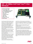
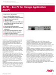
F21P Data Sheet - 2012-09-04
Embedded Solutions
F21P - 3U CompactPCI® PlusIO
Intel® Core™ i7 CPU Board
n
n
n
n
n
n
n
n
n
n
The F21P versatile 4HP/3U single-board computer is a
continuation of MEN's proven range of Intel® CPU
boards. It is equipped with the high-performance
second generation Intel® Core™ i7 processor running at
2.1 GHz and offering the latest quad core processor
architecture from Intel® with full 64-bit support. The
CPU card delivers an excellent graphics performance
and is designed especially for embedded systems which
require high computing performance with low power
consumption.
The F21P offers a 32-bit/33-MHz CompactPCI® bus
interface and can also be used without a bus system. 4
USB 2.0 ports, 4 PCI Express® x1 links, 2 SATA 3 Gb/s
and 2 SATA 6 Gb/s interfaces as well as one Gigabit
Ethernet are led to the J2 rear I/O connector which is
compatible with the PICMG 2.30 CompactPCI® PlusIO
specification.
The F21P is equipped with a state-of-the-art fast DDR3
DRAM which is soldered to the F21P to guarantee
optimum shock and vibration resistance. An mSATA disk
and a microSD™ card device which are connected via a
USB interface and a SATA channel offer nearly
unlimited space for user applications.
The standard I/O available at the front panel of F21P
includes graphics on a VGA connector, two PCIe®-driven
Gigabit Ethernet as well as two USB 2.0 ports.
The F21P can be extended by different side cards.
Additional functions include a digital video interface
1
Intel® Core™ i7, 2.1 GHz (2nd gen)
Quad-core 64-bit processor
For CompactPCI® 2.0 systems or CompactPCI®
PlusIO 2.30 hybrid systems (2.0 and CPCI-S.0)
Up to 16 GB DDR3 DRAM soldered, ECC
microSD™ card and mSATA slots
Front I/O: VGA, 2 Gbit Ethernet, 2 USB
Rear I/O: 4 PCIe®, 4 USB, 4 SATA, 1 Gbit
Ethernet
Other I/O (onboard, side card): SATA, SDVO,
HDMI/Display Port, HD audio, USB, UART etc.
2.0 to 3.0 GHz Turbo Boost, Hyper-Threading,
Active Management Technology
Open CL 1.1 support
for flat panel connection via DVI (multimedia), a
variety of different UARTs or another four USBs, SATA
for hard disk connection and HD audio.
Thermal supervision of the processor and a watchdog
for the operating system complete the functionality of
the F21P. As an option, a TPM (Trusted Platform
Module) chip can be assembled.
The F21P operates in Windows® and Linux environments
as well as under real-time operating systems that
support Intel®'s multi-core architecture. The
InsydeH2O™ EFI BIOS was specially designed for
embedded system applications.
Equipped with Intel® components exclusively from the
Intel® Embedded Line, the F21P has a guaranteed
minimum standard availability of 7 years.
The F21P is suited for a wide range of industrial
applications, e.g. for monitoring, vision and control
systems as well as test and measurement. Main target
markets comprise industrial automation, multimedia,
traffic and transportation, aerospace, shipbuilding,
medical engineering and robotics.
The F21P comes with a tailored passive heat sink
within 4 HP height. The robust design of the F21P make
the board especially suited for use in rugged
environments with regard to shock and vibration
according to applicable DIN, EN or IEC industry
standards. The F21P is also ready for coating so that
it can be used in humid and dusty environments.
®
F21P Data Sheet - 2012-09-04
Embedded Solutions
Technical Data
CPU
n Intel® Core™ i7-2715QE
o Up to 2.1 GHz processor core frequency
o 3 GHz maximum turbo frequency
n Chipset
o Intel® QM67 Platform Controller Hub (PCH)
Memory
n Up to 6 MB last level cache integrated in i7
n Up to 16 GB SDRAM system memory
o Soldered
o DDR3 with ECC support
o 1066/1333/1600 MHz memory bus frequency
n 64 Mbits boot Flash
n Serial EEPROM 2kbits for factory settings
Mass Storage
n microSD™ card interface
o Connected via one USB port
n mSATA disk slot
o Connected via one SATA channel
n Serial ATA (SATA)
o Four channels via rear I/O, one channel via side-card
connector, one channel for mSATA disk
o 4 SATA 3 Gbit/s interfaces, 2 SATA 6 Gbit/s interfaces
(rear I/O)
o RAID level 0/1/5/10 support
Graphics
n Integrated in QM67 chipset
o 650 MHz graphics base frequency
o 1.2 GHz graphics maximum dynamic frequency
n VGA connector at front panel
n Two digital display interface ports available via
side-card connector
o DisplayPort®, HDMI and SDVO (SDVO only on one
interface)
o One additional DVI connector at front panel optional
via side card
o Simultaneous connection of two monitors
I/O
n USB
o Two USB 2.0 ports via Series A connectors at front
panel
o Four USB 2.0 ports via side-card connector
o Four USB 2.0 ports via rear I/O
o One USB for connection of microSD™
o UHCI implementation
o Data rates up to 480 Mbit/s
n Ethernet
o Two 10/100/1000Base-T Ethernet channels at the front
2
RJ45 connectors at front panel
Ethernet controllers are connected by two x1 PCIe®
links
o Onboard LEDs to signal activity status and connection
speed
o One 10/100/1000Base-T Ethernet channel via rear I/O
o Ethernet controller is connected by one x1 PCIe® link
High Definition (HD) audio
o Accessible via side-card connector
o
o
n
Front Connections (Standard)
n VGA
n Two USB 2.0 (Series A)
n Two Ethernet (RJ45)
Rear I/O (PICMG 2.30)
n Four SATA
n Four USB
n One Gigabit Ethernet (second rear interface instead of
one front interface as an assembly option)
n Four PCI Express® x1 links
n Compatible with PICMG 2.30 CompactPCI® PlusIO
o 1PCI33/4PCIE5/2SATA3/2SATA6/4USB2/1(2)ETH1G
Miscellaneous
n Board controller
n Real-time clock, buffered by a GoldCap or alternatively a
battery (5 years life cycle)
n Watchdog timer
n Temperature measurement
n One user LED
n Reset button
PCI Express®
n Three x1 links to connect local 1000Base-T Ethernet
controllers
o Data rate 250 MB/s in each direction (2.5 Gbit/s per
lane)
n Four x1 links via rear I/O
o Data rate up to 500 MB/s in each direction (5 Gbit/s
per lane)
n Three x1 links for extension through side-card connector
o Data rate up to 500 MB/s in each direction (5 Gbit/s
per lane)
CompactPCI® Bus
n Connection via PCI Express® link from processor using
PCI-Express-to-PCI-Bridge
n Compliance with CompactPCI® Core Specification PICMG 2.0
R3.0
n System slot
n 32-bit/33-MHz CompactPCI® bus
n V(I/O): +3.3V (+5V tolerant)
®
F21P Data Sheet - 2012-09-04
Embedded Solutions
Technical Data
Busless Operation
n Board can be supplied with +5V only, all other voltages
are generated on the board
n Backplane connectors used only for power supply
EMC
n Tested according to EN 55022 (radio disturbance), IEC
61000-4-3 (electromagnetic field immunity), IEC 61000-4-4
(burst) and IEC 61000-4-6 (conducted disturbances)
Electrical Specifications
n Supply voltage/power consumption (board versions with
i7-2715QE processor)
o +5V (-3%/+5%), 9.6 A typ., 14.4 A max.
o +3.3V (-3%/+5%), 1.8 A (3 Gb Ethernet), 1.4 A (2 Gb
Ethernet), 1 A (1 Gb Ethernet)
o +12V (-10%/+10%), approx. 10 mA
o If the board is supplied with 5V only (typically
without a bus connection), the 3.3V are generated on
the board and fed to the backplane (3A max.) No
external 3.3 V voltage may be applied in that case!
BIOS
n InsydeH2O™ UEFI Framework
Mechanical Specifications
n Dimensions: conforming to CompactPCI® specification for
3U boards
n Front panel: 4HP with ejector
n Weight: 204 g (w/o heat sink)
Environmental Specifications
n Temperature range (operation):
o Depends on system configuration (CPU, hard disk, heat
sink...)
o Maximum: +85°C
o Minimum: -40°C (all processors)
o Conditions: airflow 1.5m/s, typical power dissipation:
12 W (board versions with i7-2715QE processor) with
Windows® XP operating system and 1 Gb Ethernet
connection
n Temperature range (storage): -40..+85°C
n Relative humidity (operation): max. 95% non-condensing
n Relative humidity (storage): max. 95% non-condensing
n Altitude: -300m to + 2,000m
n Shock: 50 m/s², 30 ms
n Vibration (Function): 1 m/s², 5 Hz - 150 Hz
n Vibration (Lifetime): 7.9 m/s², 5 Hz - 150 Hz
n Conformal coating on request
Intel® Active Management Technology
n Manageability Engine in Chipset
n Network Filters in Chipset
n Dedicated Flash Storage Area
n Out of Band (OOB) Access
o Power off Access
o Independent of OS status
o Power status control
o Keyboard-Video-Mouse (KVM) Viewer (VNC-compatible)
o IDE-Redirect
o Serial-over-LAN
Software Support
n Note that 64-bit hardware technology can be used in an
optimal way with 64-bit operating system support
n Windows®
n Linux
n VxWorks® (on request)
n QNX® (on request)
n Intel® Virtualization Technology, allows a platform to
run multiple operating systems and applications in
independent partitions; one computer system can function
as multiple "virtual" systems
n For more information on supported operating system
versions and drivers see Software.
MTBF
n 417,879 h @ 40°C according to IEC/TR 62380 (RDF2000)
Safety
n PCB manufactured with a flammability rating of 94V-0 by
UL recognized manufacturers
3
®
F21P Data Sheet - 2012-09-04
Embedded Solutions
Diagram
4
®
F21P Data Sheet - 2012-09-04
Embedded Solutions
Configuration & Options
Standard Configurations
Article No.
CPU Type
CPU Frequency
System RAM
Side Card Slot
Operating
Temperature
02F021P06
Core i7-2715QE
2.1/3.0 GHz
4 GB
right
0..60°C screened
02F021P07
Core i7-2610UE
1.5 GHz
4 GB
right
0..60°C screened
Options
CPU
n Intel® Core™ i7-2715QE, 2.1 GHz, 6 MB Cache, 45 W
n Intel® Core™ i7-2655LE, 2.2 GHz, 4 MB Cache, 25 W
n Intel® Core™ i7-2610UE, 1.5 GHz, 4 MB Cache, 17 W
n Intel® Core™ i5-2515E, 2.5 GHz, 3 MB Cache, 35 W
n Intel® Core™ i3-2340UE, 1.3 GHz, 3 MB Cache, 17 W
n Intel® Core™ i3-2310E, 2.1 GHz, 3 MB Cache, 35 W
n Intel® Celeron® B810E, 1.6 GHz, 2 MB Cache, 35 W
n Intel® Celeron® 847E, 1.1 GHz, 2 MB Cache, 17 W
n Intel® Celeron® 827E, 1.4 GHz, 1.5 MB Cache, 17 W
Memory
n System RAM
o Up to 16 GB
n microSD™ card
o 0 MB up to maximum available
n mSATA disk
o 0 MB up to maximum available
Operating Temperature
n Depends on system configuration (CPU, hard disk, heat
sink...)
n Maximum: +85°C
n Minimum: -40°C (all processors)
Cooling Concept
n Also available with conduction cooling in MEN CCA frame
Please note that some of these options may only be
available for large volumes. Please ask our sales staff
for more information.
Graphics
n One DVI-D connector at front via side card
o Simultaneous connection of two monitors
I/O
n Ethernet
o 9-pin D-Sub connector with one or two 10/100Base-T
ports instead of two RJ45 connectors
o Second Ethernet at rear I/O connector J2 instead of
one interface at the front
n Rear I/O
o VGA on CompactPCI® J2 connector as an assembly option
for the conduction-cooled board version
o VBATT on CompactPCI® J1 connector as an assembly
option for the conduction-cooled board version
Miscellaneous
n TPM (Trusted Platform Module) chip assembled as an option
Mechanical
n Side card can be added at left or right side of CPU
5
®
F21P Data Sheet - 2012-09-04
Embedded Solutions
Ordering Information
Standard F21P Models
02F021P06
Intel® Core™ i7-2715QE, 2.1 GHz, 4 GB DDR3
DRAM with ECC, 0..+60°C screened
02F021P07
Intel® Core™ i7-2610UE, 1.5 GHz, 4 GB DDR3
DRAM with ECC, 0..+60°C screened
0701-0046
CompactPCI® 19" 4U/24HP desktop system for
3U cards, 3-slot 3U CompactPCI® backplane,
system slot right, 1U fan tray with 1 fan,
8 HP space for 1 pluggable PSU
0701-0056
CompactPCI® 19" 4U/84HP rack-mount
enclosure for 3U cards (vertical), 4+4-slot
3U CompactPCI® / CompactPCI® Serial hybrid
backplane, prepared for rear I/O, 250W
power supply wide range 90..264VAC on rear,
1U fan tray with 2 fans included, 0..+60°C
Related Hardware
02F600-00
2 COM extensions and SATA hard disk slot,
for F14 and compatible SBCs, -40..+85°C
screened
02F601-00
1 DVI-D and 1 audio at front, SATA hard
disk slot, for F14 and compatible SBCs,
4HP, 0..+60°C
02F603-00
3U CompactPCI® side card with 2 USB and 1
COM extension, SATA hard disk and
CompactFlash® slot, for F14 and compatible
SBCs, mounted to the right of the SBC,
0..+60°C
02F604-00
3U CompactPCI® side card with 1 IEEE 1394
FireWire, 1 DVI, 1 HD audio and 1 COM
extension, SATA hard disk slot, for F14 and
compatible SBCs, mounted to the right of
the SBC, 0..+60°C
02F606-00
02F608-00
08CT12-00
2 Gigabit Ethernet on Lemo railway
compliant connectors, 1 COM extension
(SA-Adapter™ not included), SATA hard disk
slot, for F14 and compatible SBCs,
conformally coated, -40...+85°C screened
4 SATA and 2 COM ports, additional SATA
hard disk slot on-board, for F14 and
compatible SBCs, mounted to the right of
the SBC, 0..+60°C
CompactPCI® PlusIO rear transition module
3U/80mm, 2 Ethernet, 4 USB, 4 SATA, 4 PCIe®
x1, -40°C..+85°C qualified
Miscellaneous Accessories
0713-0003
Software: Linux
This product is designed to work under Linux. See below
for potentially available separate software packages from
MEN.
13XM01-06
MDIS5™ low-level driver sources (MEN) for
XM1, XM1L, MM1, XM2, F11S, F19P, F21P, G20,
SC21 and DC2 board controller
13Y004-06
MDIS5™ low-level driver sources (MEN) for
generic SMBus driver for F14, F15, F17,
F18, F19P, F21P, G20, D9, D601, F600 and
F601, A19, A20, F217 and SC24
Software: Windows
This product is designed to work under Windows®. See
below for potentially available separate software
packages from MEN.
10F014-78
Windows® XP Embedded BSP (MEN) for F11S,
F14, F15, F17, F18, F19P, F21P, G20, XM1,
XM1L, XM2, MM1, MM2, SC21, SC24, DC1, DC2,
RC1 and BC50M
10Y000-78
Windows® Embedded Standard 7 BSP for F11S,
F19P, F21P, G20, XM1L, XM2, MM1, MM2, SC21,
SC24, BC50M, F206, F210, F215, F216, G215,
P506, P507 and P511
13F021P77
Windows® Installset (MEN) for F21P
[Includes all free drivers developed by MEN
for the supported hardware.]
13T003-70
Windows® chipset driver (Intel®) for F14,
F15, F17, F18, F18E, F19P, F21P, G20, XM2,
D9, D6, D7, D601, A19 and A20
Memory
0751-0046
MicroSD card, 2 GB, -40..+85°C
0751-0051
SSD mSATA, 8 GB, -40..+85°C
0751-0052
MicroSD card, 4 GB, -40..+85°C
Systems & Card Cages
MEN delivers turn-key systems completely installed
(hardware, operating system, accessories), wired and
tested. Different rack sizes, power supplies and
backplanes on request.For details please contact your
local sales representative.
6
CompactPCI® 3U 1-slot backplane for
stand-alone operation of F14, F15, F17,
F18, F19P, F21P: 32-bit/33-MHz with rear
I/O, 3.3V supply, ATX-power, power, JTAG,
IPMB and utility connection, 6x screw
connection M3
®
F21P Data Sheet - 2012-09-04
Embedded Solutions
Ordering Information
13T005-70
Windows® USB2UART driver (FTDI) for F14,
F15, F17, F18, F19P, F21P, D9, A19, A20,
XM2 and XM50 / XM51 / F50P / F50C hosts
13T006-70
Windows® HD Audio driver (Realtek) for F14,
F15, F17, F18, F19P, F21P, D9 and A19
13T010-70
Windows® 32-bit network driver (Intel®) for
XM1, XM1L, XM2, MM2, F11S, F18, F18E, F19P,
F21P, G20, GM1, GM2, G211, G211F, SC24 and
BC50M
13T020-70
Windows® 64-bit network driver (Intel®) for
F18, F18E, F19P, F21P, G20, GM1, GM2, G211,
G211F, XM2, SC24 and BC50M
13T028-70
Windows® Intel® Management Engine Driver
(Intel®) for F21P
13T031-70
Windows® XP 32-bit graphics driver (Intel®)
for F21P and G22
13T032-70
Windows® 7/Vista 32-bit graphics driver
(Intel®) for F21P and G22
13T033-70
Windows® 7/Vista 64-bit graphics driver
(Intel®) for F21P and G22
Software: Miscellaneous
Intel® software development products such as analyzers,
compilers, threading tools etc. can be downloaded under
www.intel.com/cd/software/products/asmo-na/eng/index.htm.
IA-32 Intel® Architecture Software Developer's Manuals
are available under
www.intel.com/products/processor/manuals/index.htm.
For operating systems not mentioned here contact MEN
sales.
Documentation
Compare Chart 3U CompactPCI® Serial CPU and I/O cards
Download
Compare Chart 3U CompactPCI® / PlusIO CPU cards Download
Compare Chart 3U CompactPCI® / PlusIO peripheral cards
Download
Compare Chart 3U CompactPCI® / PlusIO extension cards
Download
7
20F021PER
F21P Errata
20F021P00
F21P User Manual
21APPN014
Application Note: Switching on the AMT
function
21APPN015
Application Note: Using Real-Time Operating
Systems on MEN CPUs with InsydeH2O™ UEFI
BIOS
®
For the most up-to-date ordering information and direct
links to other data sheets and downloads, see the F21P
online data sheet under » www.men.de.
F21P Data Sheet - 2012-09-04
Embedded Solutions
Contact Information
Germany
MEN Mikro Elektronik GmbH
Neuwieder Straße 3-7
90411 Nuremberg
Phone +49-911-99 33 5-0
Fax +49-911-99 33 5-901
E-mail [email protected]
www.men.de
France
MEN Mikro Elektronik SA
18, rue René Cassin
ZA de la Châtelaine
74240 Gaillard
Phone +33 (0) 450-955-312
Fax +33 (0) 450-955-211
E-mail [email protected]
www.men-france.fr
USA
MEN Micro, Inc.
24 North Main Street
Ambler, PA 19002
Phone (215) 542-9575
Fax (215) 542-9577
E-mail [email protected]
www.menmicro.com
The date of issue stated in this data sheet refers to the Technical Data only. Changes in ordering information given herein do not affect the date of issue.
All brand or product names are trademarks or registered trademarks of their respective holders.
MEN is not responsible for the results of any actions taken on the basis of information in the publication, nor for any error in or omission from the publication.
MEN expressly disclaims all and any liability and responsibility to any person, whether a reader of the publication or not, in respect of anything, and of the
consequences of anything, done or omitted to be done by any such person in reliance, whether wholly or partially, on the whole or any part of the contents of the publication.
The correct function of MEN products in mission-critical and life-critical applications is limited to the environmental specification given for each product in the technical
user manual.The correct function of MEN products under extended environmental conditions is limited to the individual requirement specification and subsequent
validation documents for each product for the applicable use case and has to be agreed upon in writing by MEN and the customer.Should the customer purchase or use
MEN products for any unintended or unauthorized application, the customer shall indemnify and hold MEN and its officers, employees, subsidiaries, affiliates, and distributors
harmless against all claims, costs, damages, and expenses, and reasonable attorney fees arising out of, directly or indirectly, any claim or personal injury or death associated
with such unintended or unauthorized use, even if such claim alleges that MEN was negligent regarding the design or manufacture of the part.
In no case is MEN liable for the correct function of the technical installation where MEN products are a part of.
Copyright © 2012 MEN Mikro Elektronik GmbH. All rights reserved.
8
®