1
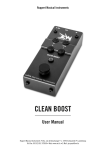
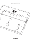
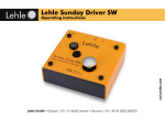
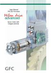
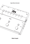
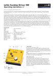
Ruppert Musical Instruments
ACOUSWITCH JUNIOR
User Manual
Ruppert Musical Instruments
20a, rue de Bascharage
L - 4995 Schouweiler
Luxembourg
Tel./Fax: 00 352 691 379050
Web: www.rmi.lu
E-Mail: [email protected]
Congratulations!
With the RMI Acouswitch Junior you have purchased a high-quality piece of musical equipment that will open up new dimensions in amplification of acoustic instruments and signal
routing. When developing the RMI Acouswitch
Junior we focused on the needs and wishes of
the professional musician who is not willing to
compromise on either sound or the technical
quality of the equipment. The RMI Acouswitch
Junior is manufactured, assembled and tested
in Germany to the highest quality standards
using only the best brand components available to ensure optimal treatment of the electrical signal from your instrument.
The RMI Acouswitch Junior is an all-rounder,
equally suitable for electric and acoustic instruments. Whether the signal comes from
a magnetic or a piezo pickup, the high-end
preamp of the RMI Acouswitch Junior will
ensure that their specific characteristics are
uncompromised.
Due to its functional design, the RMI Acouswitch Junior offers an “all-in-one” solution for
every musician who performs on stage with
both electric and acoustic instruments. The
RMI Acouswitch Junior can be used in standalone mode or as the control centre of a pedal
board.
It is an A/B input switcher, a high-end preamp, a clean booster, a 4-band EQ, an FX loop
switcher and last but not least a professional-quality active DI box. The different operating modes allow a variety of uses united in the
smallest space.
I wish you every success with your RMI Acouswitch Junior.
Yours,
Jacques Ruppert
Summary
Introduction
4
Setting the operating modes
5
Description
8
Examples of possible setups
13
Tech Talk
16
Signal Flow Diagram
18
Technical data
19
Product Guarantee
20
Introduction
Why a specific preamp/switcher/DI pedal for
acoustic instruments AND electric instruments? The reasons are obvious:
Many musicians use different instruments
on stage, switch between electric and acoustic guitars, between cello and electric guitar
or other instruments back and forth, which
they also like to independently mute, boost
or send though a few effects as well as route
them arbitrarily to an amp or to a DI-box, or a
mixer. However, acoustic instruments have a
characteristic attack with a very steep initial
transient followed by a weak electrical signal.
On top of this, the frequency range of acoustic
instruments goes from deep fundamentals
(e.g. the low C-string of a cello approx. 65 Hz)
to very high overtones that have a crucial impact on the timbre of the acoustic instrument
even though they are approaching the upper
limits of the audible spectrum.
These characteristics of acoustic signals
make enormous demands on the electronics.
Only equipment specifically designed for the
purpose is able to handle such a demanding
signal pattern adequately. The Acouswitch Junior is able to meet these requirements.
The A/B foot switch permits toggling between
the two inputs. If no cable is connected to the
instrument B input, the signal from instrument A can be routed to channel A or B by
using the A/B foot switch. Where and how your
instrument signal is switched, depends on the
selected operating mode. In Classic Mode the
selected instrument is always routed to both
outputs, whereas in Electro Acoustic Mode
the outputs are alternately muted depending
on the selected instrument input. In Teacher’s
Mode there is a mix-function, which means
that you can also toggle between A+B and B
only. For details about the switching functions
see Changing the operating mode of the A/B
switch (p. 5).
Functions and applications overview
The Acouswitch Junior offers versatile applications that can be adjusted before use.
For details on how the modes can easily be
switched see Setting the operating modes. If
you have any questions feel free to contact our
support [email protected]
- Acouswitch Junior as high-end preamp
with 4-band EQ
Channel A of the Acouswitch Junior features a
high-end preamp and a 4-band EQ specifically
designed for acoustic instruments. Featuring
bass, low mids, high mids and treble controls,
it is easy and intuitive to use.
In stand-alone use the pedal can drive a poweramp, an active monitor or an in-ear monitoring system.
Channel B pursues the philosophy of not routing the signal through unneeded electronics,
but rather keeps it pure and unprocessed. For
this reason channel B has no EQ. Since each
channel has its own volume controller, the volume of both channels can be easily balanced in
any operating mode.
- Acouswitch Junior as A/B input switcher
The inputs A and B have an impedance of
5 MOhm each. Both inputs can be used for
different instruments.
- Acouswitch Junior as FX looper
The Acouswitch Junior has one serial FX loop,
which depending on the operating mode can
be switched. In Loop Boost Mode this FX loop
4
can be switched together with the boost function. How to change the mode of the Mute/
Loop/Boost switch to Loop Boost Mode see
Changing the operating mode of the Mute/
Loop/Boost switch (p. 6).
high-quality components and features of the
Acouswitch Junior (high-end preamp, ground
switch, PRE/POST signal processing switch,
rugged construction) make the Acouswitch
Junior an excellent DI box, be it in a live setting
or in a recording situation.
- Acouswitch Junior as clean booster
Depending on the operating mode of the Mute/
Loop/Boost switch a second, controllable amplifier stage can be added via the foot switch
behind the serial FX loop.
The final amplification of the booster can be
adjusted via the BOOST potentiometer. The
mode in which the boost function is switched
exclusively is called the Boost Mode. Here, the
Mute/Loop/Boost button switches the booster
on and off. In Mute Mode this second amplifier
stage is always on, so the final volume can be
adjusted via the BOOST potentiometer.
Additional features
- TUNER OUT: Connect your tuner here to keep
it out of the signal path and prevent potential sound losses. This way the tuner can be
on all the time allowing you to check your
tuning on the fly.
- Lehle True Sound Technology (for details
please consult the chapter Tech Talk p. 16).
- Specially design to protect the controls from
damage and to prevent inadvertent changes to the settings.
- The design of the housing permits easy
installation: the ultra-flat base and removable rubber feet allow the unit to be securely
attached to the pedal board using Velcro or
similar.
- Acouswitch Junior as DI box
The Acouswitch Junior can be used to send the
output signal directly to a mixing console. The
Setting the operating modes
Changing the operating mode of the A/B switch
To change the operating mode of the A/B
switch (line-in, foot switch on the right) proceed as follows:
1. Disconnect the Acouswitch Junior from the
power supply. As a precaution, we recommend to disconnect all other cables or at
least to ensure that all devices connected to
the Acouswitch Junior are turned off. Otherwise unwanted noise could occur.
2. Keep the A/B button pressed.
3. Connect the Acouswitch Junior to the mains
supply by plugging the power supply plug
into the fitting input jack (9-15 V, leftmost)
of your Acouswitch Junior.
4. The LED above the A/B button now flashes a
sequence of 3 different flashing signals:
● • (flashes 1x)
→ Classic Mode
●● • • (flashes 2x) → Electro Acoustic Mode
●●● • • • (flashes 3x) → Teacher’s Mode
Depending on the flashing signal that is
shown at the moment you release the A/B
button, you choose Classic Mode, Electro
Acoustic Mode or Teacher’s Mode. The selected mode will stay even when you disconnect your Acouswitch Junior from the
power supply, until you set another operating mode as described above.
5
In Classic Mode input A and B are switched
alternately, so B is muted when A is on and
vice versa. If input A (INST A) is selected, the
LED above the foot switch will shine blue, if
INST B is activated, the LED will light up
(steady) white. The outputs Line Out and DI
Out are always on, so the selected instrument
signal is always routed to both outputs.
Shortly:
LED shines blue – INST A selected – EQ – Line
Out and DI Out on.
LED shines white – INST B selected – no EQ –
Line Out and DI Out on.
No mixing function.
example teacher and student).
If you switch now and the LED shines white,
only input B will be active and routed to both
outputs.
In Teacher’s Mode, the mix-function also allows to use two pickup systems for the same
instrument (e.g. mic and piezo) simultaneously
and mix, boost, switch and filter them with the
Acouswitch Junior.
Shortly:
LED shines blue – Mix on, INST A and INST B,
Line Out and DI Out on. Signal A with EQ, Signal B without EQ.
LED shines white – INST B only, Line Out and
DI Out on. The instrument signal stays clean.
In Electro Acoustic Mode, as in Classic Mode,
the two instruments are switched alternately,
so B is muted if A is on and vice versa. The
special feature of this mode is that each input is exclusively assigned to an output. The
respectively other output will then be muted.
Instrument A, which is supposed to be an
acoustic instrument, will then be routed to
the DI Out. Instrument B, an electric guitar
for example, will be solely routed to Line Out,
which could be connected to a guitar amp for
example.
Shortly:
LED shines blue – INST A selected – EQ – DI
Out on – Line Out muted.
LED shines white – INST B selected – Line Out
on – DI Out muted.
No mixing function.
Changing the operating mode of the Mute/
Loop/Boost switch
To change the operating mode of the Mute/
Loop/Boost switch (foot switch on the left)
proceed as follows:
1. Disconnect the Acouswitch Junior from the
power supply. As a precaution, we recommend to disconnect all other cables or at least
to ensure that all devices connected to the
Acouswitch Junior are turned off. Otherwise
unwanted noise could occur.
2. Keep the Mute/Loop/Boost button pressed.
3. Connect the Acouswitch Junior to the mains
supply by plugging the power supply plug
into the fitting input jack (9-15 V, leftmost)
of your Acouswitch Junior.
4. The LED above the A/B button now flashes a
sequence of 4 different flashing signals:
● • (flashes 1x)
→ Mute Mode
●● • • (flashes 2x) → Loop Mode
●● • • • (flashes 3x) → Boost Mode
• • • • (flashes 4x) → Loop Boost Mode
Depending on the flashing signal that is
shown at the moment you release the A/B
button, you choose Loop Boost Mode, Boost
In Teacher’s Mode, there is now a mixing function: If the LED shines blue, both inputs are selected and will also be routed to both outputs.
So, two instruments can be amplified simultaneously and connected e.g. with a guitar amp
via Line Out and with a mixer via DI Out. This
way, two players can use the same amp (for
6
In Boost Mode the Mute/Loop/Boost button affects only the boost function.
The serial FX loop is active whether the instrument signal is boosted or not. In this configuration, the Mute/Loop/Boost button also has no
mute function.
Shortly:
LED shines blue – Boost and Loop on, Mute
inactive.
LED is off – Boost off, Loop on, Mute inactive.
Mode or Mute Mode. The selected mode will
stay even when you disconnect your Acouswitch Junior from the power supply, until you
set another operating mode as described
above.
In Mute Mode, the serial FX loop (Loop) and
the boost are active, when the LED is off
(dark); when the LED shines blue, all will be
muted.
Shortly:
LED shines blue – Mute on – Line Out and DI
Out muted.
LED is off – Loop and Boost on.
In Loop Boost Mode, the Mute/Loop/Boost
button switches the serial FX loop along with
the booster.
In this configuration, the Mute/Loop/Boost button has no mute function. When the LED shines
blue, the Boost function (intensity can be set via
the Boost potentiometer) is selected, as is the
serial FX loop. If the LED is off, in Loop Boost
Mode boost function and FX loop are off.
Shortly:
LED shines blue – Loop and Boost on, Mute
inactive.
LED is off – Loop and Boost off, Mute inactive.
In Loop Mode, the Mute/Loop/Boost button affects only the loop function.
The serial effects loop is active when the LED
shines blue. The boost function is always active. In this configuration, the Mute/Loop/Boost
button has no mute function.
Shortly:
LED shines blue – Loop on, Boost on, Mute inactive.
LED is off – Loop off, Boost on, Mute inactive.
7
Description
7
6
5
12
11
4
10
3
9
2
1
8
19
14
13
16
15
18
20
21
17
1. Input INST A
Connect your first instrument here.
We recommend this input jack for acoustic
instruments, because this input to channel A
has the tone controls, and is routed to the DI
Out in Electro Acoustic Mode. The input gain
for this channel can be adjusted via VOL A.
pure and unprocessed. The input gain for this
channel can be adjusted via VOL B.
If only Input A is being used the foot switch
toggles the input A signal between channel A
and channel B. This allows to set up your basic
sound on your amp using the straight-through
channel B and to have a second sound-setting
available by pressing the foot switch, either for
a second instrument or for a change of style.
2. Input INST B
Connect your second instrument here – or the
2nd pickup of the same instrument.
In Electro Acoustic Mode, INST B is the appropriate input jack for the electric instrument,
because the signal from INST B then will be
routed to LINE OUT. Channel B pursues the
philosophy of not routing the signal through
unneeded electronics, but rather keeps it
3. LINE OUT
Connect your amplifier here.
When operating the Acouswitch Junior in
Electro Acoustic Mode the amp for the electric
instrument should be connected here. In this
mode, only the signal from INST B is routed to
the LINE OUT, but not the signal INST A.
8
4. TUNER OUT
Connect your tuner here.
Connecting your tuner here guarantees that
the tuner is completely out of the signal path
and does not cause sound losses. It allows you
to keep your tuner on all the time so that you
can check your tuning and intonation control
on the fly. To defeat the sound while tuning, set
the Mute/Loop/Boost button to Mute Mode and
then switch the Mute/Loop/Boost button until
the LED shines blue. Then, the MUTE button
defeats both the LINE OUT and the DI OUT.
the best out of your pedal setup we recommend
that you use high-quality power supplies with
isolated output sections in your setup!
8. Volume control channel A
Adjust with this control the volume of channel A.
This control adjusts the volume of channel
A. To permit optimal matching of the volume
between channel A and channel B this control
enables you to boost and to cut the signal, the
neutral position is at 12 o’clock. The high-end
preamp used here allows you to connect the
Acouswitch Junior directly to a power amp.
5. SEND output (Serial Loop)
Connect the first effect you want to run in the
serial loop here.
The serial loop allows to integrate an external
effects unit.
9. Bass control
Adjust with this control the amount of bass in
your tone of channel A.
The bass control B is specifically designed for
acoustic instruments in order to cut or boost
the low frequencies by +/- 15 dB with a peak
filter characteristic of about 80 Hz.
6. RETURN input (Serial Loop)
Connect the output of the last effect connected
to the SEND of the serial loop here.
If the Return jack is not used, the signal from
the send jack is present. The return socket can
also be used for a third active instrument. If
the Loop or Loop Boost Mode is active (see
Changing the operating modes of the Mute/
Loop/Boost switch), the Loop Boost button will
activate the third instrument.
10. LM control
Adjust with this control the amount of low mids
of channel A.
This control is designed for cutting and boosting the low mids by +/- 15 dB with a peak filter
characteristic. The spectrum to be controlled is
already preset and is at 360 Hz.
7. External power supply
Connect your external power supply here (9-15
V DC or 7-12 V AC; 150 mA min.).
Battery operation is not suitable for this device.
The external power supply should provide not
less than 9 V and not more than 15 V. Either
alternating (AC) or direct current (DC) sources
can be used and the polarity is not relevant. AC
power sources from 7 to 12 V can also be used.
The voltage supplied is internally rectified, filtered, stabilised and then brought to 18 V. To get
11. HM control
Adjust with this control the amount of high
mids of channel A.
This control is designed for cutting and boosting the high mids by +/- 15 dB with a peak
filter characteristic. The spectrum to be controlled is already preset and is at 2 kHz.
12. Treble control
Adjust with this control the amount of treble of
channel A.
9
With the treble control you can cut or boost
high frequencies by +/- 12.5 dB via a shelving
filter at 10 kHz.
LED shines white – INST B selected – Line Out
on – DI Out muted.
No mix function.
13. Volume control channel B
Adjust with this control the volume of channel B.
This control adjusts the volume of channel
B. To permit optimal matching of the volume
between channel A and channel B this control
enables you to boost and to cut the signal, the
neutral position is at 6 o’clock.
Teacher’s Mode
LED shines blue – Mix on, INST A and INST B,
Line Out and DI Out on. Signal A with EQ, Signal B without EQ.
LED shines white – INST B alone, Line Out and
DI Out on. Instrument signal stays unchanged.
For details see Changing the operating mode
of the A/B switch (p. 5).
14. BOOST control
Adjust with this control the boost level or the
output volume of the entire device.
Whether the booster is switched on or always
is on, depends on the mode of the Mute/Loop/
Boost control see Changing the operating
mode of the Mute/Loop/Boost switch (p. 6). The
booster is behind the serial FX loop. In Boost
Mode the booster can be used as solo boost.
In Loop Boost Mode the serial loop is switched
together with the Boost. For all modes applies:
BOOST control rightmost (1 o’clock): no gain;
control leftmost (11 o’clock): gain of +12 dB.
The signal level can therefore only be boosted,
but not cut with this potentiometer.
16. Status display for MUTE/LOOP BOOST
This LED shows different switching statuses
depending on the adjusted mode.
The LED shines blue, when the preset function
is on. That means:
In Mute Mode:
LED shines blue – Mute on, all is muted.
LED is off – Loop and Boost on.
In Loop Mode:
LED shines blue – Loop and Boost on, Mute
inactive.
LED is off – Loop off, Boost on, Mute inactive.
15. Status display for foot switch A/B
This LED shows different switching statuses
depending on the adjusted mode.
In Boost Mode:
LED shines blue – Boost and Loop on, Mute
inactive.
LED is off – Boost off, Loop on, Mute inactive.
Classic Mode
LED shines blue – INST A selected – EQ – Line
Out and DI Out on.
LED shines white – INST B selected – no EQ –
Line Out and DI Out on.
No mix function.
Electro Acoustic Mode
LED shines blue – INST A selected – EQ – DI
Out on – Line Out muted.
In Loop Boost Mode:
LED shines blue – Loop and Boost on, Mute
inactive.
LED is off – Loop and Boost off, Mute inactive.
For details see Change the operating mode of
the Mute/Loop/Boost switch.
10
17. A/B foot switch
Press this switch depending on the mode to
select between INST A and INST B, to route
from INST A to channel A or B or to switch between INST A + INST B or just INST B.
The function of this switch changes depending
on the selected mode. It is also dependent on
whether an instrument is connected to INST
B or not. In Classic Mode this switch toggles
between INST A and INST B, the signal is routed to both outputs. In Electro Acoustic Mode
both instrument inputs are also alternately
switched, but in this mode each input is exclusively assigned to one output, the respectively other output is then muted. Thanks to
the mix function in Teacher’s Mode there is the
option to switch INST A + INST B against INST
B alone. For details see Change the operating
modes of the A/B switch.
Is just an instrument connected to INST A and
INST B remains free, the A/B switch effects a
switchover of the input signal to channel A
with EQ or channel B. That way you can toggle with one instrument between two different
sounds.
The switched signal is symmetrically available
at the DI output. Whether and which signal is
routed to the DI Out depends on the operating
mode of the A/B switch. In Classic Mode the
selected signal is always routed to the DI Out,
whereas in Electro Acoustic Mode the DI Out
is muted, when channel B is on. In Teacher’s
Mode the selected input signal (A+B or B) is
always transmitted to the DI Out. The maximum level at the DI Out is about +10 dBU.
20. GROUND switch
Press the GROUND switch to eliminate ambient noise.
In pressed condition the shielding of the
Acouswitch Junior and the XLR cable get connected. When you have any doubts adjust the
GROUND switch through trial and error to have
no humming noise.
21. PRE/POST switch
Press the PRE/POST switch to eliminate the EQ
and the loop from the DI signal path.
By pressing this switch the signal goes directly
to the DI output without passing through the
EQ, the serial loop or the boost of the Acouswitch Junior. The Line Out is not affected. For
studio recordings it is more advantageous to
record the signal unedited and edit it later.
This setup enables the musician to hear his
recorded signals as usual with EQ and effects via Line Out in the PRE-mode, while at
the same time the signal of the instrument is
picked up directly behind the Volume control
of channel A or B and transmitted via the DI
output of the Acouswitch Junior unedited. The
effects can be added to the recording during
the mix via re-amping, which usually leads to
better results.
18. MUTE/LOOP/BOOST foot switch
Press this switch depending on the mode for
turning on/off the booster, the effects loops or
the muting.
The function of this switch changes depending
on the selected mode. You can optionally turn
on/off the boost, turn on/off the effects loop
and the boost or muting the Acouswitch Junior.
For details of the modes and how to operate
them, see Change the operating mode of the
Mute/Loop/Boost switch.
19. DI OUT
Use this output for connecting the Acouswitch
Junior with an XLR cable to a mixing console.
11
Examples of possible setups
12
1. The Acouswitch Junior as A/B-switcher/preamp/booster/DI in a stand-alone application
2. The Acouswitch Junior as A/B-switcher/preamp/booster/DI on a pedal board
LOW
MIX
LEVEL
REGEN
HIGH
RATE
DEPTH
DELAY
analog
delay
analog
chorus
13
3. The Acouswitch Junior as a preamp/booster/DI in a stand-alone application
4. The Acouswitch Junior as a preamp/booster/DI on a pedal board
LOW
MIX
LEVEL
REGEN
HIGH
RATE
DEPTH
DELAY
analog
delay
analog
chorus
14
5. The Acouswitch Junior as a preamp/booster/DI in a stand-alone application with three instruments
6. The Acouswitch Junior as A/B-switcher/preamp in a student-teacher application
15
Tech Talk
True Bypass and True Sound
Today more and more effect pedals feature
true bypass switching to completely bypass
the pedal in the signal routing when the pedal
is switched off. The target of this design is to
ensure that the pedal does not affect the electrical signal when it is switched off. This way
the sound is left unaltered - in theory.
In practice, however, connecting several pedals featuring a true bypass design in series
does not improve the sound or keep it unaltered at all. Long runs of cable and multiple
connections lead to a weak and lifeless sound.
On large pedal boards the overall length of the
cable is enough for the capacitance of the cable have a negative effect on the sound. The
capacitance of the cable acts as a low-pass
filter (= the low frequencies pass through the
filter while the high frequencies are filtered
out). The price and quality of the cable you
are using will not change this physical phenomenon.
A solution would be to use only devices with
buffered bypass design instead of true bypass. This, however, is only a good solution
if the buffer is of very high quality. If several
units with buffered bypass are connected in
series it only needs one buffer to be noisy, cut
the dynamics of the sound signal or negatively
affect the sound in any other way for the sound
of the whole effect chain to be spoilt. As the
saying goes “a chain is only as strong as its
weakest link”. In addition, the noise of the
individual buffers adds up to produce audible
noise; it is a fact that every buffer produces
some noise, even if it cannot be heard when
only a single buffer is used. The ideal solution
is to have a very high-quality buffer at the
beginning of the chain that brings the signal
down to a very low impedance. This makes the
signal insensitive to the length of the cable.
It is important, however, that this buffer is of
the highest quality with the dynamic range
and headroom necessary to ensure that all
the details of the bass signal stay are retained
unaltered.
The effect pedals in the downstream loops
should then ideally have true bypass so that
they will not have a negatively effect on the
now buffered signal, as the true bypass design does not reduce dynamics and headroom
or produce any noise. Conclusion: having a
True Sound Lehle buffer at the beginning of
your effect chain combined with good true-bypass-equipped effects in the loop guarantees
the best sound.
What is Lehle True Sound Technology?
Lehle True Sound Technology is a combination
of several electrical design measures with
only one aim in view: to transmit the sound
and the character of the instrument without
altering it. The voltage supplied to the Acouswitch Junior is internally rectified, filtered and
stabilised and then brought to 18 V. Supplying
the buffer with 18 V gives enough headroom
to guarantee an open and dynamic sound in
all situations without losing any detail, even
when confronted with pickup power peaks of
up to around 7 V. The buffers are designed
to effortlessly handle signals reaching the
megahertz range. At the output, the frequency
bandwidth is limited to prevent HF interference from, disturbing the electronic circuitry.
This technology guarantees optimal transient
response by the circuitry and is key to obtaining a sound that is transparent and, above all,
cuts through. For switching, Lehle True Sound
16
Technology uses exclusively gold-plated contact relays and/or gold-plated switches. The
decaying signal from a string is so weak that
contact materials with lower conductivity have
a negative impact on the sound. Ordinary foot
switches use contact materials developed to
switch high voltages (e.g. electrical power
tools) as this is their main field of application.
This can be heard, for example, when, after a
switch has been in use for some time, a decaying tone starts to break off abruptly. Relays
and switches with gold-plated contacts do
not have this problem and even the smallest
electrical signals can be transmitted for years
without being negatively affected. In addition,
the relays used in the Acouswitch Junior have
a lifetime about 100 times as long as those
used in ordinary foot switches. Together with
typical Lehle electronic circuitry to reduce the
switching pop of relays, the combination of
the above design features represents today’s
state-of-the-art solution for an uncompromising preservation of the signal and hence the
sound and character of the instrument.
metal lever. Because the actuator button and
the internal push button are not directly connected, the load exerted by the foot is absorbed
by the actuator button and the housing, preserving the circuit board from mechanical
stress. The design is as robust as possibly
and the actuator button mounted in a special
socket making for easy and silent operation.
Inside the Acouswitch Junior the impulse from
the push button triggers a processor based
on the ARM Cortex-M technology which controls the switching operation very quickly and
precisely. This way the switching is done only
via high-quality relays and thus guaranteeing
absolutely reliable and loss-free switching of
very sensitive signals. The switching technology and the gold-plated relays in the Acouswitch Junior are designed to operate for up to
two million switching cycles!
Working principle of the Acouswitch Junior
foot switches
Foot switches are pressed thousands of times
during their long life – sometimes sensitively
but some times more brutally depending on
the situation and the musician’s temperament. An ordinary foot switch will switch up
to 20,000 times before wearing out mechanically or electrically, which means that either
it will stop working altogether or the signal
will start to lose transparency and dynamics. The Acouswitch Junior is equipped with
high-quality Lehle foot switches. Here the foot
of the musician does not press an ordinary foot
switch but an actuator button that activates a
push button inside the Acouswitch Junior via a
17
Instr B
Signal Flow Diagram
Technical data:
Weight:
Length:
Width:
Overall height:
Voltage range:
Power consumption:
Frequency range:
Distortion:
Input A impedance:
Input B impedance:
Send impedance:
Return Impedance:
Output impedance:
Signal-to-noise ratio:
Max. level:
Max. gain:
EQ
Bass:
Low Mid:
High Mid:
Treble:
1,065 g
15 cm (5.9")
16 cm (6.3")
4.3 cm (1.7")
9-15 V DC, 7-12 V AC
max. 150 mA
50 Hz (Low-cut-Filter) – 100 kHz (+0, -2 dB)
0,005 %
5 MOhm
5 MOhm
250 Ohm
50 kOhm
250 Ohm
-94 dB at 1 kHz, 0 dBU (22 Hz - 22 kHz)
5 V RMS (ca. 16 dBU)
+/- 15 dB
+/- 15 dB @ 80 Hz (peaking)
+/- 15 dB @ 360 Hz (peaking)
+/- 15 dB @ 2 kHz (peaking)
+/- 12.5 dB @ 10 kHz (shelving)
Product Guarantee
1. This product is covered by a limited scope
Product Guarantee for a period of two years
from the date of purchase of the unit.
2. The guarantee is restricted to the free-ofcharge rectification of material and manufacturing defects by means of repair or replacement, at the manufacturer‘s option.
3. The guarantee includes free-of-charge return of the unit to the customer. The customer
shall bear the costs of returning the unit to the
Lehle Customer Service.
4. All guarantee repairs shall be performed
by a customer service organization authorized
and approved by Lehle GmbH.
5. The guarantee shall be deemed to become
null and void if the product has been modified
or damaged by incorrect use, negligence, dismantling, changes made by non-authorized
customer service organizations or by the use
of non-original spare or replacement parts.
Please proceed as follows if it should become
necessary to return your product:
1. Please firstly contact us (support@lehle.
com), in order that the fault can be ascertained
and trouble-free processing assured.
2. Please submit to us documentation (receipts or similar) clearly and unequivocally
proving the date of purchase of the unit.
3. Please send the unit carefully packed (the
original packing is best!) at your own expense
to:
Lehle GmbH
Grenzstrasse 153
46562 Voerde
Germany
or to an authorized customer service organization named by ourselves.
6. Lehle GmbH is unable to accept any liability
whatsoever for any and all consequential damage resulting from the use of this product.
Ruppert Musical Instruments
20a, rue de Bascharage
L - 4995 Schouweiler
Luxembourg
Tel./Fax: 00 352 691 379050
Web: www.rmi.lu
E-Mail: [email protected]