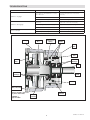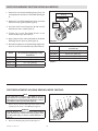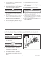
1
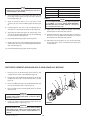
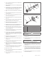
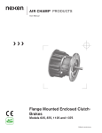
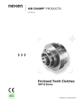
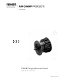
USER MANUAL FMCE Flange Mounted Clutch Models 625, 875, 1125 and 1375 FORM NO. L-20168-D-0912 1 FORM NO. L-20168-D-1112 In accordance with Nexen’s established policy of constant product improvement, the specifications contained in this manual are subject to change without notice. Technical data listed in this manual are based on the latest information available at the time of printing and are also subject to change without notice. Technical Support: 800-843-7445 (651) 484-5900 www.nexengroup.com WARNING Read this manual carefully before installation and operation. Follow Nexen's instructions and integrate this unit into your system with care. This unit should be installed, operated and maintained by qualified personnel ONLY. Improper installation can damage your system or cause injury or death. Comply with all applicable codes. Nexen Group, Inc. 560 Oak Grove Parkway Vadnais Heights, Minnesota 55127 Copyright 2012 Nexen Group, Inc. FORM NO. L-20168-D-1112 ISO 9001 Certified 2 Table of Contents Installation------------------------------------------------------------------------------------------------------------------------------------------ 4 Air Connections --------------------------------------------------------------------------------------------------------------------------------- 6 Lubrication ---------------------------------------------------------------------------------------------------------------------------------------- 6 Troubleshooting ------------------------------------------------------------------------------------------------------------------------------- 7 Parts Replacement ----------------------------------------------------------------------------------------------------------------------------- 8 Parts Lists --------------------------------------------------------------------------------------------------------------------------------------- 14 Warranty ----------------------------------------------------------------------------------------------------------------------------------------- 19 3 FORM NO. L-20168-D-1112 INSTALLATION NOTE The following sections are arranged by model. Verify that you are in the correct section for your model. FMCE 625 MOUNTED ON THE SHAFT END OF A MOTOR NOTE Align the air inlet on the FMCE, to a down position to allow condensation to drain out of the air chamber. Plug (Item 27) Set Screw (Item 26) 1. Insert the customer supplied key into the motor shaft keyway (See Figure 1). Customer supplied key 2. Slide the FMCE onto the motor shaft and secure it to the motor using Nexen supplied Socket Head Cap Screws (Item 29) and Lock Washers (Item 30) (See Figure 1). Motor 3. Alternately and evenly tighten the Socket Head Cap Screws (Item 29) to 580 In. Lbs. [65.0 N•m] torque. FMCE Housing 4. Align the Set Screw (Item 26) in the Drive Disc (Item 4) with the hole in the FMCE Housing (See Figure 1). 5. Tighten the Set Screw (Item 26); then, install the Plug (Item 27) (See Figure 1). Socket Head Cap Screw (Item 29) and Lock Washer (Item 30) FIGURE 1 FMCE 875, 1125, AND 1375 MOUNTED ON THE SHAFT END OF A MOTOR NOTE Align the air inlet on the FMCE, to a down position to allow condensation to drain out of the air chamber. Plug (Item 27) Set Screw (Item 26) 1. Insert the customer supplied key into the motor shaft keyway (See Figure 2). Socket Head Cap Screw (Item 29) and Lock Washer (Item 30) 2. Remove the Socket Head Cap Screws (Item 24) and the Female Pilot (Item 13); then, secure the Female Pilot to the motor face using Nexen supplied Socket Head Cap Screws (Item 29) and Lock Washers (Item 30) (See Figure 2). Customer supplied key 3. Alternately and evenly tighten the Socket Head Cap Screws (Item 29) to the recommended torque (See Table 1). Socket Head Cap Screws (Item 24) 4. Slide the Female Pilot (Item 13) onto the motor shaft (See Figure 2). 5. Apply a drop of Loctite® 242 to the threads of the Socket Head Cap Screws (Item 24) (See Figure 2). Motor 6. Secure the FMCE Housing (Item 1) to the Female Pilot (Item 13) using Socket Head Cap Screws (Item 24); then, alternately and evenly tighten the Socket Head Cap Screws to the recommended torque (See Figure 2 and Table 1). 7. Female Pilot (Item 13) FIGURE 2 RECOMMENDED TIGHTENING TORQUE Align the Set Screw (Item 26) in the Drive Disc (Item 4) with the hole in the FMCE Housing (See Figure 2). 8. Tighten the Set Screw (Item 26); then, install the Plug (Item 27) (See Figure 2). MODEL TIGHTENING TORQUE FMCE 875 (Item 24) 157 In. Lbs. [17.7 N m] FMCE 1125 (Item 24) 267 In. Lbs. [30.2 N m] 580 In. Lbs. [65.0 N m] FMCE 1375 (Item 24) FMCE 875 (Item 29) 580 In. Lbs. [65.0 N m] FMCE 1125 (Item 29) 1425 In. Lbs. [159.6 N m] FMCE 1375 (Item 29) 1425 In. Lbs. [159.6 N m] TABLE 1 FORM NO. L-20168-D-1112 FMCE Housing 4 FMCE 625 MOUNTED BETWEEN A GEAR REDUCER AND A MOTOR NOTE Align the air inlet on the FMCE, to a down position to allow condensation to drain out of the air chamber. Customer supplied socket head cap screws, lock washers, and nuts 1. Insert the Key (Item 25) into the output shaft of the FMCE (See Figure 3). Plug (Item 27) 2. Slide the FMCE output shaft into the gear reducer (See Figure 3). Set Screw (Item 26) 3. Secure the FMCE to the gear reducer using customer supplied socket head cap screws, lock washers, and nuts (See Figure 3). Key (Item 25) Customer supplied key 4. Insert the customer supplied key into the motor shaft keyway (See Figure 3). Motor 5. Slide the motor into the FMCE and secure it to the FMCE using Nexen supplied Socket Head Cap Screws (Item 29) and Lock Washers (Item 30) (See Figure 3). Gear Reducer 6. Alternately and evenly tighten the Socket Head Cap Screws (Item 29) to 580 In. Lbs. [65.0 N•m] torque. 7. Align the Set Screw (Item 26) in the Drive Disc (Item 4) with the hole in the FMCE Housing (See Figure 3). Socket Head Cap Screw (Item 29) and Lock Washer (Item 30) 8. Tighten the Set Screw (Item 26); then, install the Plug (Item 27) (See Figure 3). FMCE Housing FIGURE 3 FMCE 875, 1125, AND 1375 MOUNTED BETWEEN A GEAR REDUCER AND A MOTOR NOTE Align the air inlet on the FMCE, to a down position to allow condensation to drain out of the air chamber. Set Screw (Item 26) 1. Insert the Key (Item 25) into the output shaft of the FMCE (See Figure 4). Customer supplied socket head cap screws, lock washers, and nuts Plug (Item 27) 2. Slide the FMCE output shaft into the gear reducer (See Figure 4). Gear Reducer Socket Head Cap Screw (Item 29) and Lock Washer (Item 30) 3. Secure the FMCE to the gear reducer using customer supplied socket head cap screws, lock washers, and nuts (See Figure 4). Customer supplied key 4. Insert the customer supplied key into the motor shaft keyway (See Figure 4). 5. Remove the Socket Head Cap Screws (Item 24) and the Female Pilot (Item 13); then, secure the Female Pilot to the motor face using Nexen supplied Socket Head Cap Screws(Item 29) and Lock Washers (Item 30); then, alternately and evenly tighten the Socket Head Cap Screws to the recommended torque (See Figure 4 and Table 2). Key (Item 25) Socket Head Cap Screws (Item 24) Motor FMCE Housing 6. Slide the Female Pilot (Item 13) onto the motor shaft (See Figure 4). Female Pilot 7. Apply a drop of Loctite® 242 to the threads of the Socket Head Cap Screws (Item 24) (See Figure 4). FIGURE 4 5 (Item 13) FORM NO. L-20168-D-1112 8. Secure the FMCE Housing (Item 1) to the Female Pilot (Item 13) using Socket Head Caps Screws (Item 24). Then, alternately and evenly tighten the Socket Head Cap Screws to the recommended torque (See Figure 4 and Table 2). RECOMMENDED TIGHTENING TORQUE 9. Align the Set Screw (Item 26) in the Drive Disc (Item 4) with the hole in the FMCE Housing (See Figure 4). MODEL TIGHTENING TORQUE FMCE 875 (Item 24) 157 In. Lbs. [17.7 N m] FMCE 1125 (Item 24) 267 In. Lbs. [30.2 N m] 580 In. Lbs. [65.0 N m] FMCE 1375 (Item 24) 10. Tighten the Set Screw (Item 26); then, install the Plug (Item 27) (See Figure 4). FMCE 875 (Item 29) 580 In. Lbs. [65.0 N m] FMCE 1125 (Item 29) 1425 In. Lbs. [159.6 N m] FMCE 1375 (Item 29) 1425 In. Lbs. [159.6 N m] TABLE 2 AIR CONNECTIONS NOTE For quick response, Nexen recommends a quick exhaust valve and short air lines between the Control Valve and the FMCE. Align the air inlet port to a down position to allow condensation to drain out of the air chamber of the FMCE. LUBRICATION NOTE Pneumatically actuated devices require clean, pressure regulated, and lubricated air for maximum performance and long life. The most effective and economical way to lubricate the FMCE is with an Air Line Lubricator, which injects oil into the pressurized air, forcing an oil mist into the air chamber. Locate the lubricator above and within ten feet of the FMCE, and use a low viscosity oil such as SAE-10. Synthetic lubricants are not recommended. LUBRICATOR DRIP RATE SETTINGS NOTE These settings are for Nexen supplied lubricators. If you are not using a Nexen lubricator, calibration must replicate the following procedure. 1. Close and disconnect the air line from the unit. 5. Connect the air line to the unit. 2. Turn the Lubricator Adjustment Knob clockwise three complete turns. 6. Turn the Lubricator Adjustment Knob counterclockwise until closed. 3. Open the air line. 7. Turn the Lubricator Adjustment Knob clockwise one-third turn. 4. Close the air line to the unit when a drop of oil forms in the Lubricator Sight Gage. FORM NO. L-20168-D-1112 8. Open the air line to the unit. 6 TROUBLESHOOTING SYM PTOM Failure to engage. Failure to disengage. Loss of Torque. PROBAB LE CAUS E SOLUTION Air not getting to the FMCE due to a control valve malfunction. Check for a control valve malfunction or low air pressure and replace the control valve if necessary. Lack of lubrication on the Stub Shaft spline. Lubricate the Stub Shaft spline. Air leaks around the O-ring Seals. Replace the O-ring Seals. Unexhausted air due to a control valve malfunction. Check for a control valve malfunction and replace the control valve if necessary. Weak or damaged Conpression Springs. Replace the Compression Springs. Lack of lubrication on the Stub Shaft spline. Lubricate the Stub Shaft spline. Air leaks around the O-ring Seals. Replace the O-ring Seals. Worn or dirty Fiction Facing. Replace the Friction Facing. Splined Disc Housing Compression Spring O-ring Seals Male Pilot Dowel Pin Drive Disc Ball Bearings Key Ball Bearings Stub Shaft Piston Female Pilot (875,1125,1375) (Pilot is integral to the housing in the 625 model.) FIGURE 5 Typical FMCE Air Chamber Friction Facing 7 FORM NO. L-20168-D-1112 PARTS REPLACEMENT–FRICTION FACING (ALL MODELS) 1. Remove the four Socket Head Cap Screws (Item 12) and separate the two halves of the FMCE (See Figure 6). Socket Head Cap Screw (Item 12) Friction Facing (Item 8) 2. Remove the six old Flat Head Screws (Item 7) and the old Friction Facing (Item 8) (See Figure 6). Flat Head Screw (Item 7) 3. Install the new Friction Facing (Item 8) and new Flat Head Screws (Item 7) (See Figure 6). 4. Tighten the six new Flat Head Screws to the recommended torque (See Table 3). 5. Apply a drop of Loctite 242 to the threads of the Socket Head Cap Screws (Item 12) (See Figure 6). FIGURE 6 6. Reinstall and tighten the four Socket Head Cap Screws (Item 12) to the recommended torque (See Table 4). Model Recommended Tightening Torque for (Item 10) FMCE 625 157 In. Lbs. [17.7 Nm] FMCE 875 266 In. Lbs. [30.0 Nm] FMCE 1125 266 In. Lbs. [30.0 Nm] FMCE 1375 594 In. Lbs. [55.5 Nm] Model Recommended Tightening Torque for (Item 7) FMCE 625 26 In. Lbs. [2.9 Nm] FMCE 875 26 In. Lbs. [2.9 Nm] FMCE 1125 71 In. Lbs. [8.0 Nm] FMCE 1375 71 In. Lbs. [8.0 Nm] TABLE 4 TABLE 3 PARTS REPLACEMENT–HOUSING BEARING, MODEL FMCE 625 NOTE If an Input Unit is installed on the FMCE, it must be removed before servicing the FMCE. Remove the Plug (Item 27) and loosen the Set Screw (Item 26) to release the FMCE from the Input Unit (See Figure 7). 2 27 1 1. Remove the four Socket Head Cap Screws (Item 12) and separate the two halves of the FMCE (See Figure 7). 6 WARNING Special attention should be exercised when working with retaining rings. Always wear safety goggles when working with spring or tension loaded fasteners or devices. FIGURE 7 2. Remove the Retaining Ring (Item 6) (See Figure 7). FORM NO. L-20168-D-1112 8 3 4 26 12 3. Press the Drive Disc (Item 4) out of the Bearing (Item 2) and the Housing (Item 1) (See Figure 7). 10. Reinstall the Retaining Ring (Item 3) (See Figure 7). 11. Support the inner race of the new Bearing (Item 2) and press the Drive Disc (Item 4) into the new Bearing and Housing (Item 1) (See Figure 7). 4. Remove the Retaining Ring (Item 3) (See Figure 7). 5. Fully supporting the Housing (Item 1), press the old Bearing (Item 2) out of the Housing (Item 1) (See Figure 7). 12. Reinstall the Retaining Ring (Item 6) (See Figure 7). NOTE Do not reuse the bearing. Applying force to the inner bearing race to remove a bearing held by the outer race causes damage to the bearing. NOTE If you are replacing all the Bearings and O-ring Seals in the FMCE, proceed to PARTS REPLACEMENT– BEARINGS AND O-RING SEALS; otherwise, proceed with the next step. 6. Clean the bearing bore of the Housing (Item 1) with fresh safety solvent, making sure all old Loctite® residue is removed (See Figure 7). 13. Apply a drop of Loctite® 242 to the threads of the Socket Head Cap Screws (Item 12) (See Figure 7). 7. Apply an adequate amount of Loctite® 680 to evenly coat the outer race of the new Bearing (Item 2) (See Figure 7). 14. Slide the Housing (Item 1), Bearing (Item 2), and Drive Disc (Item 4) into the FMCE and reinstall the four Socket Head Cap Screws (Item 12) (See Figure 7). 8. Carefully align the outer race of the new Bearing (Item 2) with the bore of the Housing (Item 1) (See Figure 7). 15. Tighten the four Socket Head Cap Screws (Item 12) to 157 In. Lbs. [17.7 N•m] torque. 9. Supporting the Housing (Item 1) and pressing on the outer race of the new Bearing (Item 2), press the new Bearing into the Housing (See Figure 7). PARTS REPLACEMENT–FEMALE PILOT BEARING, MODELS FMCE 875, 1125, AND 1375 NOTE If an Input Unit is installed on the FMCE, it must be removed before servicing the FMCE. Remove the Plug (Item 27) and loosen the Set Screw (Item 26) to release the FMCE from the Input Unit (See Figure 8). 1 Female Pilot (Item 13) 3 1. Remove the four Socket Head Cap Screws (Item 24) and remove the Female Pilot (Item 13) from the FMCE Housing (Item 1) (See Figure 8). 4 27 24 26 2 6 WARNING Special attention should be exercised when working with retaining rings. Always wear safety g o g g l e s wh e n wo rk i n g wi t h s p ri n g or te nsi o n loaded fasteners or devices. 2. Remove the Retaining Ring (Item 6) (See Figure 8). FIGURE 8 3. Press the Drive Disc (Item 4) out of the Bearing (Item 2) and the Female Pilot (Item 13) (See Figure 8). 4. Remove the Retaining Ring (Item 3) (See Figure 8). 5. Fully supporting the Female Pilot (Item 13), press the old Bearing (Item 2) out of the Female Pilot (Item 13) (See Figure 8). 9 FORM NO. L-20168-D-1112 NOTE Do not reuse the bearing. Applying force to the inner bearing race to remove a bearing held by the outer race causes damage to the bearing. RECOMMENDED TIGHTENING TORQUE 6. Clean the bearing bore of the Female Pilot (Item 13) with fresh safety solvent, making sure all old Loctite® residue is removed (See Figure 8). 7. MODEL TIGHTENING TORQUE FMCE 875 (Item 24) 157 In. Lbs. [17.7 N m] FMCE 1125 (Item 24) 266 In. Lbs. [30.0 N m] FMCE 1375 (Item 24) 580 In. Lbs. [65.0 N m] TABLE 5 NOTE If you are replacing all the Bearings and O-ring Seals in the FMCE, proceed to PARTS REPLACEMENT– BE AR I NGS AN D O - R I NG SE ALS; other wise, proceed with the next step. Apply an adequate amount of Loctite ® 680 to evenly coat the outer race of the new Bearing (Item 2) (See Figure 8). 8. Carefully align the outer race of the new Bearing (Item 2) with the bore of the Female Pilot (Item 13) (See Figure 8). 13. Apply a drop of Loctite® 242 to the threads of the Socket Head Cap Screws (Item 24) (See Figure 8). 9. Supporting the Female Pilot (Item 13) and pressing on the outer race of the new Bearing (Item 2), press the new Bearing into the Female Pilot (See Figure 8). 14. Slide the Female Pilot (Item 13), Bearing (Item 2), and Drive Disc (Item 4) into the FMCE and reinstall the four Socket Head Cap Screws (Item 24) (See Figure 8). 10. Reinstall the Retaining Ring (Item 3) (See Figure 8). 15. Alternately and evenly tighten the four Socket Head Cap Screws (Item 24) to the recommended torque (See Figure 13 and Table 5). 11. Support the inner race of the new Bearing (Item 2) and press the Drive Disc (Item 4) into the new Bearing and Female Pilot (Item 13) (See Figure 8). 12. Reinstall the Retaining Ring (Item 6) (See Figure 8). PARTS REPLACEMENT–BEARINGS AND O-RING SEALS (ALL MODELS) 1. Remove the four Socket Head Cap Screws (Item 12) and separate the two halves of the FMCE (See Figure 9). 12 21 2. Remove the four Socket Head Cap Screws (Item 12) securing the Male Pilot (Item 19) to the Air Chamber (Item 11) (See Figure 9). 12 11 3. Remove the Male Pilot (Item 19) and Stub Shaft (Item 22) from the Air Chamber (Item 11) (See Figure 9). 19 4. Remove and discard the old O-ring Seals (Items 20 and 21) (See Figure 9). 22 WARNING The Piston (Item 15) is spring loaded. Always wear safety goggles when working with spring or tension loaded fasteners or devices. 5. Using a "C" clamp, compress the Piston (Item 15) into the Air Chamber (Item 11) (See Figure 10). FIGURE 9 WARNING Special attention should be exercised when working with retaining rings. Always wear safety goggles when working with spring or tension loaded fasteners or devices. FORM NO. L-20168-D-1112 20 10 6. Remove the Retaining Ring (Item 6) from the Splined Disc (Item 9) (See Figure 10). 2 10 7. Press the Splined Disc (Item 9) from the Bearing (Item 2) (See Figure 10). 11 9 8. Slowly release the "C" clamp holding the Piston (Item 15) in the Air Chamber (Item 11); then, remove the Piston (Item 15) from the Air Chamber (Item 11) (See Figure 10). 3 6 15 14 9. Remove the six Compression Springs (Item 10) (See Figure 10). 10. Remove the Retaining Ring (Item 3) from the Piston (Item 15) (See Figure 10). FIGURE 10 11. Remove and discard the old O-ring Seal (Item 14) from the Piston (Item 15) (See Figure 10). 12. Press the Bearing (Item 2) out of the Piston (Item 15) (See Figure 15). 18 23 18 22 13. Clean the bearing bore of the Piston with fresh safety solvent, making sure all old Loctite® residue is removed. 19 14. Apply an adequate amount of Loctite® 680 to evenly coat the outer race of the new Bearing (Item 2). 15. Carefully align the outer race of the new Bearing (Item 2) with the bore of the Piston (Item 15) (See Figure 10). FIGURE 11 16. Supporting the Piston (Item 15) and pressing on the outer race of the new Bearing (Item 2), press the new Bearing into the Piston (See Figure 10). Model 17. Reinstall the Retaining Ring (Item 3), securing the Bearing to the Piston (Item 15) (See Figure 10). Recommended Tightening Torque for (Item 12) FMCE 625 157 In. Lbs. [17.7 Nm] FMCE 875 266 In. Lbs. [30.0 Nm] FMCE 1125 266 In. Lbs. [30.0 Nm] FMCE 1375 594 In. Lbs [55.5 Nm] 18. Coat the O-ring contact surfaces of the Air Chamber (Item 11), Piston (Item 15), and the O-ring Seal (Item 14) with a thin film of O-ring lubricant and install the new O-ring Seal (See Figure 10). TABLE 6 19. Reinstall the six Compression Springs (Item 10) into the Air Chamber (Item 11) (See Figure 10). 27. Press the old Bearing (Item 18) off the Stub Shaft (Item 22) (See Figure 11). 20. Slide the Piston (Item 15) into the Air Chamber (Item 11) (See Figure 10). 28. Press the old Bearing (Item 18) out of the Male Pilot (Item 19) (See Figure 11). 21. Using a "C" clamp, compress the Piston (Item 15) into the Air Chamber (Item 11) (See Figure 10). NOTE It is not necessary to remove the Retaining Ring (Item 17) from the inside of the Male Pilot (Item 19). NOTE One Bearing (Item 18) will remain attached to the Stub Shaft (Item 22). 22. Support the inner race of the Bearing (Item 2) and press the Splined Disc (Item 9) into the Bearing and Piston (Item 15) (See Figure 10). 29. Clean the bearing bore of the Male Pilot (Item 19) with fresh safety solvent, making sure all old Loctite® residue is removed (See Figure 11). 23. Reinstall the Retaining Ring (Item 6) that secures the Splined Disc (Item 9) to the Bearing (Item 2) (See Figure 10). 30. Apply an adequate amount of Loctite® 680 to evenly coat the outer race of the first new Bearing (Item 18) and press it into the output side of the Male Pilot until it is seated against the Retaining Ring (Item 17) inside the Male Pilot (See Figure 11). 24. Remove the "C" clamp. 25. Remove the Retaining Ring (Item 23) from the Stub Shaft (Item 22) (See Figure 11). 31. Press the second new Bearing (Item 18) onto the Stub Shaft (Item 22) (See Figure 11). 26. Press the Stub Shaft (Item 22) out the Male Pilot (Item 19) (See Figure 11). 11 FORM NO. L-20168-D-1112 32. Apply an adequate amount of Loctite® 680 to evenly coat the outer race of the second new Bearing (Item 18). 40. Slide the Male Pilot (Item 19) and Stub Shaft (Item 22) into the FMCE. 33. Carefully align the outer race of the second new Bearing (Item 18) with the bore of the Male Pilot (Item 19) (See Figure 11). 41. Apply a drop of Loctite® 242 to the threads of four Socket Head Cap Screws (Item 12) (See Figure 9). 34. While supporting the Male Pilot (Item 19) and the inner race of the first new Bearing (Item 18) and pressing on the outer race of the second new Bearing (Item 18), press the second new Bearing and Stub Shaft (Item 22) into the Male Pilot (See Figure 11). 42. Tighten the four Socket Head Cap Screws (Item 12) that secure the Male Pilot (Item 19) to the Air Chamber (Item 11) to the recommended torque (See Table 7). 43. Apply a drop of Loctite® 242 to the threads of the remaining four Socket Head Cap Screws (Item 12) (See Figure 9). 35. Reinstall the Retaining Ring (Item 23) (See Figure 16). 44. Slide the Air Chamber (Item 11) into the Housing (Item 1) and install the four remaining Socket Head Cap Screws (Item 12) that secure the Air Chamber to the Housing (See Figure 9). 36. Apply a thin film of NEVER-SEEZ® to the splines of the Stub Shaft (Item 22) (See Figure 11). 37. Coat the O-ring contact surfaces of the Male Pilot (Item 19), Piston (Item 15), and the O-ring Seals (Items 20 and 21) with a thin film of O-ring lubricant. 45. Tighten the four Socket Head Cap Screws (Item 12) that secure the Air Chamber (Item 11) to the Housing (Item 1) to the recommended torque (See Figure 9 and Table 6). 38. Install the new O-ring Seals (Items 20 and 21) (See Figure 9). 39. Align the Dowel Pins (Item 16) in the Male Pilot (Item 19) with the holes in the Piston (Item 15) (See Figure 9). PARTS REPLACEMENT—INPUT UNIT WARNING Special attention should be exercised when working with retaining rings. Always wear safety goggles when working with spring or tension loaded fasteners or devices. 20 Press this Ball Bearing onto the Stub Shaft. 1. Remove the Retaining Ring (Item 35) from the output end of the Input Unit (See Figure 12). NOTE One old Ball Bearing (Item 30) will come out of the Bearing Flange (Item 20) with the Stub Shaft (Item 11). 30 3. Press the first old Ball Bearing (Item 30) off the Stub Shaft (Item 11) (See Figure 12). FIGURE 12 4. Press the first new Ball Bearing (Item 30) onto the Stub Shaft (Item 11) until it is seated against the Retaining Ring (Item 35) (See Figure 12). 5. Press the second old Ball Bearing (Item 30) out of the Bearing Flange (Item 20) (See Figure 12). FORM NO. L-20168-D-1112 12 30 35 Remove first. 11 2. Press the Stub Shaft (Item 11) out of the Bearing Flange (Item 20) (See Figure 12). 58 Do not remove Retaining Ring (Item 35). Do not remove. 6. Clean the bearing bore of the Bearing Flange (Item 20) with fresh safety solvent, making sure all old Loctite® residue is removed (See Figure 12). 8. Apply an adequate amount of Loctite® 680 to evenly coat the outer race of the second new Ball Bearing (Item 30) and press the second new Ball Bearing onto the Stub Shaft (Item 11) and into the Bearing Flange (Item 20) until the Ball Bearing is seated against the Retaining Ring (Item 58) (See Figure 12). 7. Apply an adequate amount of Loctite® 680 to evenly coat the outer race of the first new Ball Bearing (Item 30) on the Stub Shaft (Item 11) and press the first new Ball Bearing and Stub Shaft into the Bearing Flange (Item 20) until the Ball Bearing is seated against the Retaining Ring (Item 58) (See Figure 12). 9. Reinstall the Retaining Ring (Item 35) (See Figure 12). REPLACEMENT PARTS number, part description, and quantity. Purchase replacement parts through your local Nexen Distributor. The item or balloon number for all Nexen products is used for part identification on all product parts lists, product price lists, unit assembly drawings, bills of materials, and instruction manuals. When ordering replacement parts, specify model designation, item 13 FORM NO. L-20168-D-1112 PARTS LIST FMCE 625 11 9 14 12 10 8 4 27 6 3 7 26 2 1 12 16 5 18 23 17 19 21 6 2 22 3 20 18 15 FIGURE 13 ITEM DESCRIPTION QTY 1 Housing 1 21Bearing 2 3 Retaining Ring (Int.) 2 4 Drive Disc 1 5 Retaining Ring (Int.) 1 6 Retaining Ring (Ext.) 2 72 Flat Head Screw 6 82 Friction Facing 1 9 Splined Disc 1 10 Compression Spring 6 11 Air Chamber 1 12 Socket Head Cap Screw 8 141 O-ring Seal 1 15 Piston 1 1 Denotes Repair Kit item. Repair Kit No. 801487. ITEM QTY 16 Slotted Spring Pin 17 Retaining Ring (Int.) 181Bearing 19 Male Pilot 201 O-ring Seal 211 O-ring Seal 22 Stub Shaft 23 Retaining Ring (Ext.) 25 Key (Not Shown) 26 Set Screw 27 Plug 29 Socket Head Cap Screw (Not Shown) 30 Lock Washer (Not Shown) 2 FORM NO. L-20168-D-1112 DESCRIPTION 14 Denotes Facing Kit item. Facing Kit No. 801448. 1 1 2 1 1 1 1 1 1 1 1 4 4 FMCE 875 12 10 14 11 9 8 7 27 1 4 2 26 12 5 3 24 16 13 6 17 23 18 19 18 17 21 20 22 15 2 6 3 FIGURE 14 ITEM DESCRIPTION ITEM QTY DESCRIPTION QTY 16 Slotted Spring Pin 17 Retaining Ring (Int.) 181Bearing 19 Male Pilot 201 O-ring Seal 211 O-ring Seal 22 Stub Shaft 23 Retaining Ring (Ext.) 24 Socket Head Cap Screw 25 Key (Not Shown) 26 Set Screw 27 Plug 29 Socket Head Cap Screw (Not Shown) 30 Lock Washer (Not Shown) 1 Housing 1 21Bearing 2 3 Retaining Ring (Int.) 2 4 Drive Disc 1 5 Retaining Ring (Int.) 1 6 Retaining Ring (Ext.) 2 Flat Head Screw 6 72 82 Friction Facing 1 9 Splined Disc 1 10 Compression Spring 6 11 Air Chamber 1 12 Socket Head Cap Screw 8 13 Female Pilot 1 141 O-ring Seal 1 15 Piston 1 1 Denotes Repair Kit item. Repair Kit No. 801474. 2 15 1 1 2 1 1 1 1 1 4 1 1 1 4 4 Denotes Facing Kit item. Facing Kit No. 801477. FORM NO. L-20168-D-1112 FMCE 1125 12 10 14 11 9 8 7 27 1 4 2 26 12 5 3 24 16 13 6 17 23 18 19 18 17 21 20 22 15 2 6 3 FIGURE 15 ITEM DESCRIPTION QTY ITEM 1 Housing 1 21Bearing2 3 Retaining Ring (Int.) 2 4 Drive Disc 1 5 Retaining Ring (Int.) 1 6 Retaining Ring (Ext.) 2 72 Flat Head Screw 6 82 Friction Facing 1 9 Splined Disc 1 10 Compression Spring 6 11 Air Chamber 1 12 Socket Head Cap Screw 8 13 Female Pilot 1 141 O-ring Seal 1 1 Denotes Repair Kit item. Repair Kit No. 918378. FORM NO. L-20168-D-1112 DESCRIPTION QTY 15 Piston 16 Slotted Spring Pin 17 Retaining Ring (Int.) 181Bearing 19 Male Pilot 201 O-ring Seal 211 O-ring Seal 22 Stub Shaft 23 Retaining Ring (Ext.) 24 Socket Head Cap Screw 25 Key (Not Shown) 26 Set Screw 27 Plug 29 Socket Head Cap Screw (Not Shown) 30 Lock Washer (Not Shown) 2 Denotes Facing Kit item. Facing Kit No. 801605. 16 1 2 1 2 1 1 1 1 1 4 1 1 1 4 4 FMCE 1375 12 10 14 11 9 8 7 27 1 4 2 26 12 5 3 24 16 13 6 17 23 18 19 18 17 21 20 22 15 2 6 3 FIGURE 16 ITEM DESCRIPTION QTY ITEM 1 Housing 1 21Bearing2 3 Retaining Ring (Int.) 2 4 Drive Disc 1 5 Retaining Ring (Int.) 1 6 Retaining Ring (Ext.) 2 72 Flat Head Screw 6 82 Friction Facing 1 9 Splined Disc 1 10 Compression Spring 6 11 Air Chamber 1 12 Socket Head Cap Screw 8 13 Female Pilot 1 141 O-ring Seal 1 15 Piston 1 1 Denotes Repair Kit item. Repair Kit No. 918379. DESCRIPTION QTY 16 Slotted Spring Pin 17 Retaining Ring (Int.) 181Bearing 19 Male Pilot 201 O-ring Seal 211 O-ring Seal 22 Stub Shaft 23 Retaining Ring (Ext.) 24 Socket Head Cap Screw 25 Key (Not Shown) 26 Set Screw 27 Plug 29 Socket Head Cap Screw (Not Shown) 30 Lock Washer (Not Shown) 2 17 2 1 2 1 1 1 1 1 4 1 1 1 4 4 Denotes Facing Kit item. Facing Kit No. 801647. FORM NO. L-20168-D-1112 PARTS LIST–INPUT UNIT ITEM 11 19 20 30 35 45 58 DESCRIPTION QTY Stub Shaft Key Bearing Flange Ball Bearing Retaining Ring Hex. Head Jam Nut (Not Shown) Retaining Ring 1 2 1 2 2 4 1 58 30 19 35 11 30 35 FIGURE 17 FORM NO. L-20168-D-1112 18 20 WARRANTY Warranties Nexen warrants that the Products will (a) be free from any defects in material or workmanship for a period of 12 months from the date of shipment, and (b) will meet and perform in accordance with the specifications in any engineering drawing specifically for the Product that is in Nexen’s current product catalogue, or that is accessible at the Nexen website, or that is attached to this Quotation and that specifically refers to this Quotation by its number, subject in all cases to any limitations and exclusions set out in the drawing. NEXEN MAKES NO OTHER WARRANTY, EXPRESS OR IMPLIED, AND ALL IMPLIED WARRANTIES, INCLUDING WITHOUT LIMITATION, IMPLIED WARRANTIES OF MERCHANTABILITY AND FITNESS FOR A PARTICULAR PURPOSE ARE HEREBY DISCLAIMED. This warranty applies only if: (a) the Product has been installed, used and maintained in accordance with any applicable Nexen installation or maintenance manual for the Product; (b) the alleged defect is not attributable to normal wear and tear; (c) the Product has not been altered, misused or used for purposes other than those for which it was intended; and (d) Buyer has given written notice of the alleged defect to Nexen, and delivered the allegedly defective Product to Nexen, within one year of the date of shipment. Exclusive Remedy The exclusive remedy for the Buyer for any breach of any warranties provided in connection with this agreement will be, at the election of Nexen: (a) repair or replacement with new, serviceably used, or reconditioned parts or products; or (b) issuance of credit in the amount of the purchase price paid to Nexen by the Buyer for the Products. Agent's Authority Buyer agrees that no agent, employee or representative of Nexen has authority to bind Nexen to any affirmation, representation, or warranty concerning the Products other than those warranties expressly set forth herein. Limitation on Nexen’s Liability TO THE EXTENT PERMITTED BY LAW NEXEN SHALL HAVE NO LIABILITY TO BUYER OR ANY OTHER PERSON FOR INCIDENTAL DAMAGES, SPECIAL DAMAGES, CONSEQUENTIAL DAMAGES OR OTHER DAMAGES OF ANY KIND OR NATURE WHATSOEVER, WHETHER ARISING OUT OF BREACH OF WARRANTY OR OTHER BREACH OF CONTRACT, NEGLIGENCE OR OTHER TORT, OR OTHERWISE, EVEN IF NEXEN SHALL HAVE BEEN ADVISED OF THE POSSIBILITY OR LIKELIHOOD OF SUCH POTENTIAL LOSS OR DAMAGE. For all of the purposes hereof, the term "consequential damages" shall include lost profits, penalties, delay damages, liquidated damages or other damages and liabilities which Buyer shall be obligated to pay or which Buyer may incur based upon, related to or arising out of its contracts with its customers or other third parties. In no event shall Nexen be liable for any amount of damages in excess of amounts paid by Buyer for Products or services as to which a breach of contract has been determined to exist. The parties expressly agree that the price for the Products and the services was determined in consideration of the limitation on damages set forth herein and such limitation has been specifically bargained for and constitutes an agreed allocation of risk which shall survive the determination of any court of competent jurisdiction that any remedy herein fails of its essential purpose. Inspection Buyer shall inspect all shipments of Products upon arrival and shall notify Nexen in writing, of any shortages or other failures to conform to these terms and conditions which are reasonably discoverable upon arrival without opening any carton or box in which the Products are contained. Such notice shall be sent within 14 days following arrival. All notifications shall be accompanied by packing slips, inspection reports and other documents necessary to support Buyer's claims. In addition to the foregoing obligations, in the event that Buyer receives Products that Buyer did not order, Buyer shall return the erroneously shipped Products to Nexen within thirty (30) days of the date of the invoice for such Products; Nexen will pay reasonable freight charges for the timely return of the erroneously shipped Products, and issue a credit to Buyer for the returned Products at the price Buyer paid for them, including any shipping expenses that Nexen charged Buyer. All shortages, overages and nonconformities not reported to Nexen as required by this section will be deemed waived. Limitation on Actions No action, regardless of form, arising out of any transaction to which these terms and conditions are applicable may be brought by the Buyer more than one year after the cause of action has accrued. Nexen Group, Inc. 560 Oak Grove Parkway Vadnais Heights, MN 55127 800.843.7445 Fax: 651.286.1099 www.nexengroup.com ISO 9001 Certified 19 FORM NO. L-20168-D-1112