1
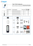
Why just THROW the
ball to Her?
When you can BE THE
BALL for Her?
Go from traditional
throw and catch to
so much more...
»» Play with Her even
when you cannot get
aroud that well.
»» Give Her more of a
challenge.
Stray Pooch
Table of Contents
Abstract .........................................................................................................................................3
Features and Usability .................................................................................................................3
Productibility ................................................................................................................................4
User Manual .................................................................................................................................5
Instructions ........................................................................................................................................................ 5
Contents ............................................................................................................................................................. 5
Trouble Shooting ............................................................................................................................................... 6
Industry Standards, Patent Research, and Liability ................................................................7
Figures ...........................................................................................................................................8
Assembly Drawings........................................................................................................................................... 8
Support Structure ............................................................................................................................................. 14
Schematics ....................................................................................................................................................... 16
Codes ...........................................................................................................................................19
Computer Software .......................................................................................................................................... 20
Toy Software ................................................................................................................................................... 21
Bill of Materials ..........................................................................................................................22
For H-Bridge Schematic Version 3.2 .............................................................................................................. 22
For Assembly Drawings .................................................................................................................................. 23
For Computer Hardware .................................................................................................................................. 24
Bottom Line ..................................................................................................................................................... 24
Wrap-Up .....................................................................................................................................25
Presented by:
Allen Clark w Kieu Dinh w Bilal Haroon w Richard Hosch
Abstract:
They say dog is man’s best friend; for the elderly this is exceptionally true. Finding
a way to allow those who have pets but are unable to interact with them do to
limited mobility is the whole goal of the Stray Pooch Dog Toy. The Stray Pooch
Toy itself comprises of micro-controllers, two hobby motors, a gearbox, and a
single axle support frame. To be included in the overall process is the XBee
transmitter and receiver set; this allows the toy to be controlled by a laptop or
desktop computer system. For the software, there are two programs: one for the
micro-controller and the other for the computer to send commands to the ball via
the XBee set (i.e. push the “s” button for forward movement and the “w” button for
the opposite direction). It is the idea that this new concept of interacting with a dog
will work on an acceptable level given the right breed combination, (meaning the
size of toy is not intimidating to the dog,) and some encouragement from the dog’s
owner. Interest in the Stray Pooch design has been addressed among family and
friends of the designers and improvements have been acknowledged and not yet
implemented based on the comments provided to the designers.
Features and Usability:
This toy was designed to have the most efficient means of motion, spherical. This
will allow the user to have control without planning a complex route to control the
toy. An obvious feature and the primary reason for the overall design is that the toy
is remote controlled from a computer. This provides those with limited mobility an
easier way to play with their beloved pets. The prototype is designed to have all
electronics within the spherical shell preventing the beloved pet from destroying the
toy. Talking to the family and friends of the design group prompted a consensus:
the prototype, and the concept that surrounds it, looks promising, however, they
would not purchase the toy as it is now. Some key features that should be looked
into are as follows: have a user-friendly power switch and look into a plug and play
design.
3
Productibility:
The construction of this toy is fairly simple and easy to mass-produce. One of the
requirements though would be investing more time for research and development to
reduce the size of the toy from 11.5 inches to say eight or nine inches along with
designing a less sophisticated design for the support and housing of the toy’s
internal components. A bill of materials for the current prototype will be presented
later on, however, this design will have a price range, for the parts only, of $100.00
to $126.00 depending on if the parts were bought at bulk. Again, this is a prototype
design for proof of concept and it is recommended that further development along
with stricter cost analysis is needed to build a profitable design for marketability.
4
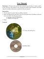
User Manual:
Disclaimer: All topics discussed in this section are general ideas of what could be
in here, however, this product is not yet ready for market and it should be noted that
when it is, further elaboration is needed for the user manual.
Instructions
1. Check contents to ensure that everything is present.
2. Insert installation disk and follow the auto run instructions (if problems with auto
run occur follow the directions below).
a. Navigate to the CD-ROM drive
b. Double click setup.exe
3. Enjoy
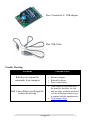
Contents
11.5” Stray Pooch Dog Toy
Installation Disk
5
Xbee Transmitter w/ USB adaptor
Mini USB Cable
Trouble Shooting
Problem
Possible Fixes
•
•
•
•
Ball does not respond to
commands from computer
Ensure that the battery is installed
Restart computer
Reinstall software
Press restart button
• There might be a problem with
the gearbox, therefore, for this
and any other problems not listed,
visit the following website to get
in contact with the manufacturer:
• Tech Support Page
Ball is not rolling even though the
motors are moving
6
Industry Standards, Patent Research, and Liability:
Given this design uses a non-rechargeable battery, industry standards for the toy are
not applicable, however, if the toy did have the ability to recharge itself, then proper
labeling would be needed on the charger. This label would inform the users to such
things as input and output voltages and currents. Warning symbols might tell the
user to properly dispose of the charger, and caution statements that inform the user
to only plug the toy into a grounded outlet. Further elaboration involving the
development of this portion would be needed once a marketable product is made.
Good news, nobody else, from the research conducted, has developed the same idea
as the Stray Pooch Design Team did. The following describes, along with provides
links to the patents themselves, ideas that have similar concepts as the Stray Pooch:
• Training Guidance System-- Patent No.: US 7,861,676 B2
• Pet Entertainment System--Pub. No.: US 2008/0282988 A1
The following are possible liability statements to incorporate into the user manual
once a consumer product is developed:
• In the following “we, us, the group” indicates all who participated in the
design and fabrication of the Stray Pooch Dog Toy.
• By “pet” we mean a dog or a cat.
• By “toy” we mean the Stray Pooch Dog Toy.
• We are not responsible for lost pets.
• This toy is designed for appropriate use. This means:
o Playing with a pet in a manner that does not endanger the pet owner or
the pet itself.
o No liability can be incurred due to, any incidents or damages that occur
while using this toy in any unintended function.
• Any alterations done on the toy, either mechanical or electrical, will result in
freeing us from any liability.
7
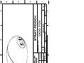
Figures:
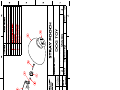
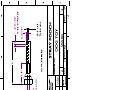
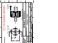
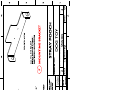
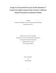
Assembly Drawings:
These drawings are the working views of the toy itself. All models were created in
CATIA V5R18, a computer-aided 3D designing software that allows visualization
of virtual models in real-time. These assembly drawings were used to create
multiple working prototypes of the toy.
The first sheet shows a completely assembled toy, as it will appear to the pet. The
second sheet shows an exploded view of toy with each part labeled. The remaining
sheets show each of the 3 parts that were manufactured.
8
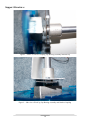
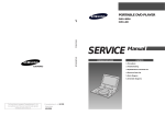
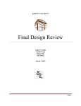
Support Structure:
Figure 1 -- Photo of Gearbox Coupling, Cap Bearing Assembly and End Cap
Figure 2 -- Side view of End Cap, Cap Bearing Assembly and Gearbox Coupling
14
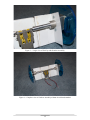
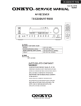
Figure 3 -- Larger view of End Cap with Gearbox Assembly
Figure 4 -- Complete view of Gearbox Assembly without circuit board attached
15
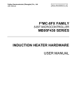
Figure 5 -- Rear view of Gearbox Assembly showing attachment of the gearbox itself
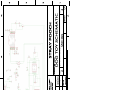
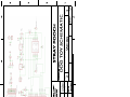
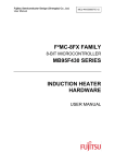
Schematics:
Three major versions of the electrical schematics were generated. The first version
created was a complete mockup of the Arduino Microcontroller design, the motor
driver circuit that had been created for early testing as well as an XBee adapter
circuit. This schematic was never produced for a circuit board, as there were
several unneeded items. This version was striped down considerably and was
eventually replaced with “version 3.2.” This version striped the original design of
everything except the microcontroller, the buffer for the XBee and the motor driver.
Headers were added to allow testing of the circuit, giving the schematic a rather
chunky size. In the latest version, “version 3.3” the headers were removed as well
as the buffer since it was determined through testing this buffer did not affect the
readings received from the XBee module.
Two versions are shown below, version 3.2 and 3.3.
16
Codes:
Software was produced to make this toy functional, one for the computer and one
for the toy itself. All software was written in the C language due to its relative ease
of learning and versatility. The toy software was written in an Arduino designing
environment using the Arduino Software written by the open source group of the
same name available at the Arduino Source page. This environment runs entirely
within C and uses a serial connection to push the user-created software to the
microcontroller. The computer software was generated using the Processing
environment. Again, this is an open source environment designed to allow users to
generate C programs for deployment on multiple platforms. It is capable of using
the USB and serial ports on any machine as an input and output means of
communication. This capability was exploited to allow the XBee module (which
connects to a USB port) to communicate with the toy wirelessly as if it were a
directly attached peripheral.
19
Computer Software:
/*This is the computer software generated in Processing.
As W is pressed on the keyboard, the speed of the motor will increase in the forward direction.
Pressing S will increase in the reverse direction.*/
import
processing.serial.*;
Serial port;
int counter = 0; //Defines a counter and stores 0
String data = "\r"; //Defines the string “data” and stores a carriage return
void setup()
{
size(100,100);
println(Serial.list());
/*The first port in the serial list on the computer is always the last item to be connected.
For the purposes of this demonstration, Serial.list()[0] is used, the first port is opened.*/
port = new Serial(this,Serial.list()[0],9600);
}
void draw()
{
rect(25, 25, 50, 50); //Draws arbitrary box within window.
if (keyPressed == true)
{
/*This loop is performed only when the “W” key is pressed.*/
if( key == 'w')
{
counter++;
delay(100);
//Once the counter reaches 256, it will become to 255(since 255 is the max). This will cap the speed at 256
if ( counter == 256)
{
counter = 255;
}
}
/*This loop is performed only when the “W” key is pressed.*/
if (key == 's')
{
counter--;
delay(100);
//Once the counter reaches -256, it will become to -255(since -255 is the max). This will cap the speed at -256
if ( counter == -256)
{
counter = -255;
}
}
}
else
{
counter = 0;
}
fill(counter);
data = ""+counter+"\r"; //Generates string to send over serial connection
port.write(data); //Sends data string through the serial connection
}
20
Toy Software:
/*This is the toy software written in Arduino. It will convert the incoming bytes into integer values which will control the speeds of the motor.*/
#define
#define
#define
#define
#define
#define
#define
#define
switchPin 2
motor1Pin 3
motor2Pin 4
motor3Pin 6
motor4Pin 7
enable1Pin 9
enable2Pin 10
ledPin 13
char value_read[5];
int speed_value = 0;
void setup()
{
Serial.begin(9600);
Serial.flush();
//Switch input
//Motor 1 leg 1
//Motor 1 leg 2
//Motor 2 leg 1
//Motor 2 leg 2
//Motor1 enable
//Motor2 enable
//Reset LED
(pin
(pin
(pin
(pin
pin
pin
3)
6)
11)
14)
//Define char array for reading serial values
//Define an initial speed
//Turn on the Serial Port at 9600 bps
//Clear all serial inputs
/*Set all the other pins you're using as outputs*/
pinMode(motor1Pin, OUTPUT);
pinMode(motor2Pin, OUTPUT);
pinMode(motor3Pin, OUTPUT);
pinMode(motor4Pin, OUTPUT);
pinMode(enable1Pin, OUTPUT);
pinMode(enable2Pin, OUTPUT);
pinMode(ledPin, OUTPUT);
/* Blink the LED 3 times. This should happen only once. If you see the LED blink three times, it means that the module reset itself, probably because
the motor caused a brownout or a short. */
blink(ledPin, 3, 100);
}
void loop()
{
int x;
int i = 0;
//Sets storage variable for Serial.read()
//Defines a counter for while loop
/*As long as the incoming serial byte is not a carriage return or new line the values will be stored in the value_read array*/
while(((x = Serial.read()) != 13) && ( x != 10 ))
{
if( x != -1)
//If the incoming byte is not -1 (no value)
{
value_read[i++] = x;
//Stores the incoming number in char array
}
value_read[i] = '\0';
//Sets last value (carriage return) to null
}
/*Converts the char array to integer value*/
speed_value = atoi(value_read);
/*If speed value greater than zero, the direction of
if( speed_value > 0 )
{
analogWrite(enable2Pin, speed_value);
digitalWrite(motor3Pin, HIGH);
//Set
digitalWrite(motor4Pin, LOW);
//Set
analogWrite(enable1Pin, speed_value);
digitalWrite(motor1Pin, HIGH);
//Set
digitalWrite(motor2Pin, LOW);
//Set
}
/*If speed value less than zero, the direction
if (speed_value < 0 )
{
analogWrite(enable2Pin, speed_value*-1);
digitalWrite(motor3Pin, LOW );
digitalWrite(motor4Pin, HIGH);
analogWrite(enable1Pin, speed_value*-1);
digitalWrite(motor1Pin, LOW);
digitalWrite(motor2Pin, HIGH);
}
motors will spin forward*/
leg 1 of the Motor2 high
leg 2 of the Motor2 low
leg 1 of the Motor1 high
leg 2 of the Motor1 low
of motors will spin backward*/
//Set leg 1 of the Motor2 high
//Set leg 2 of the Motor2 low
//Set leg 1 of the Motor1 high
//Set leg 2 of the Motor1 low
/*If no key is pressed, no movement will occur*/
if( speed_value == 0 )
{
digitalWrite(enable2Pin, LOW);
digitalWrite(enable1Pin, LOW);
}
}
/*Blinks the LED signifying restart*/
void blink(int whatPin, int howManyTimes, int milliSecs)
{
int i = 0;
for ( i = 0; i < howManyTimes; i++)
{
digitalWrite(whatPin, HIGH);
delay(milliSecs/2);
digitalWrite(whatPin, LOW);
delay(milliSecs/2);
}
}
21
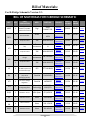
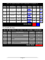
Bill of Materials:
For H-Bridge Schematic Version 3.2:
BILL OF MATERIALS FOR H-‐BRIDGE SCHEMATIC REF. QTY PART DESCRIPTION MFG. PART NO. SOURCE XBEE 1 XBee DigiMesh 2.4 Module (any XBee modem will function) Digi XB24-‐
DMWIT-‐250 Mouser Electronics
8-‐bit ATMEGA microcontroller Atmel ATMEGA8-‐
16PU Mouser Electronics
28-‐pin IC socket 3M 4828-‐3004-‐CP Mouser Electronics
1 ZIC1 1 1 IC3 1 1 IC1 1 Y2 Q1 IC2 IC4 R1,R2 R3 1 1 1 1 2 1 R4,R5,R7,
R8 4 R6,R9 2 5V compliant buffer chip 14-‐pin IC socket 36V Quad Half H-‐
Bridge 16-‐pin IC socket Texas SN74AHC125
Instruments N 3M 4814-‐3004-‐CP Mouser Electronics
Mouser Electronics
Texas Mouser SN754410NE Instruments Electronics
3M 4816-‐3000-‐CP Mouser Electronics
16 MHz Resonator (16 MHz crystal may be used with caps) ECS BJT NPN Transistor (any TO-‐92 packaging will do) Fairchild 5V Linear Voltage Regulator Fairchild 3.3V Low Drop Out Voltage Regulator Microchip Technology MCP1700-‐
3302E/TO Mouser Electronics
200 Ohm resistor KOA Speer CF1/4C201J Mouser Electronics
1 Mohm resistor 1 Kohm resistor 10 Kohm resistor Xicon Xicon Xicon ZTT-‐16.00MX FJN3303FBU LM7805CT 299-‐1M-‐RC 291-‐1.5K-‐RC 291-‐10K-‐RC 22
Mouser Electronics
Mouser Electronics
Mouser Electronics
Mouser Electronics
Mouser Electronics
Mouser Electronics
PRICE PRICE PER UNIT PER 100 $19.00 $19.00 DATASHEET
$ 2.61 $ 2.08 DATASHEET
$ 0.31 $ 0.21 DATASHEET
$ 0.56 $ 0.30 DATASHEET
$ 0.13 $ 0.09 DATASHEET
$ 2.30 $ 1.66 DATASHEET
$ 0.13 $ 0.09 DATASHEET
$ 0.50 $ 0.35 DATASHEET
$ 0.20 $ 0.15 DATASHEET
$ 0.54 $ 0.40 DATASHEET
$ 0.40 $ 0.28 $ 0.15 $ 0.10 DATASHEET
$ 0.10 $ 0.06 DATASHEET
$ 0.10 $ 0.05 DATASHEET
$ 0.10 $ 0.05 DATASHEET
BILL OF MATERIALS FOR H-‐BRIDGE SCHEMATIC REF. QTY PART DESCRIPTION MFG. PART NO. SOURCE C1 -‐ C6 6 0.1 uF (100nF) capacitor Xicon 140-‐50V5-‐
104Z-‐RC Mouser Electronics
140-‐
MLNP10V47-‐
RC Mouser Electronics
929870-‐01-‐
06-‐RA Mouser Electronics
929870-‐01-‐
08-‐RA Mouser Electronics
M22-‐7131042 Mouser Electronics
PC1 -‐ PC3 3 POWER & AD 2 IOL & IOH 2 PINHD 2 47 uF capacitor 6-‐pin header 8-‐pin header 10-‐pin header (2mm) Xicon 3M 3M Harwin PRICE PRICE PER UNIT PER 100 $ 0.28 $ 0.16 DATASHEET
$ 0.35 $ 0.27 DATASHEET
$ 0.71 $ 0.59 DATASHEET
$ 0.95 $ 0.75 DATASHEET
$ 1.60 $ 0.99 DATASHEET
$36.93 $31.61 TOTAL PRICE: PER UNIT PER 100 For Assembly Drawings:
BILL OF MATERIALS FOR DOG TOY ASSEMBLY DRAWINGS REF. QTY. A B C D E F G-‐H UNLISTED UNLISTED 2 2 2 2 1 1 1 2 4 PART DESCRIPTION Manufactured from radial aluminum 1/4 ID 3/4 OD Radial Ball Bearing Manufactured from stock aluminum 2.5" 1/4 Hex Bolt Gearbox Manufactured from sheet aluminum Plastic Hamster Ball 0.25" 6-‐32 Machine Screw 0.5" 10-‐32 Machine Screw SOURCE The Yard BRC Bearing The Yard Ace Hardware Sparkfun The Yard PetsMart Ace Hardware Ace Hardware TOTAL PRICE: 23
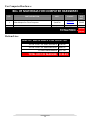
PRICE $2.50 $3.92 $2.50 $0.20 $19.99 $2.50 $19.99 $0.04 $0.05 per lbs. per unit per lbs. per unit per unit per unit per unit per unit per unit $60.72 PER UNIT For Computer Hardware:
BILL OF MATERIALS FOR COMPUTER HARDWARE QTY. 1 PART DESCRIPTION MFG. Xbee Adapter for Client Computer PRICE PER UNIT SOURCE SparkFun SparkFun Electronics
Newegg.com
$24.95 1 USB Cable Bytecc TOTAL PRICE: Bottom Line:
BILL OF MATERIALS FOR DOG TOY TOTAL COST OF ELECTRONICS $36.93 TOTAL COST OF MECHANICAL $60.72 OTHER HARDWARE $27.94 TOTAL COST OF MACHINE $125.59 24
$2.99 $27.94 PER UNIT Wrap-Up:
This toy was initially designed to give those who have to travel a means to play
with their beloved pets via the Internet. At first we, the Stray Pooch Dog Toy
group, were making great strides at accomplishing this goal during the first
semester of the senior design class. We established proof of concepts for both the
wireless communications, between the toy and a joystick, and an intranet website
that streamed live video feed. Then the second semester hit; which ushered in
reality for our group. One of the first problems: the construction of the toy itself.
We realized that the prototype developed for the first semester was inadequate
structurally and needed redesigning to be more effective at supporting the inner
workings of the toy and providing an axis of rotation. The next problem that set
before us was updating the programming to allow a computer to act as the joystick
for the ball. This proved exceptionally difficult for our group since the level of
programming experience for the group was minimal at best.
From our initial design, things had to be cut due to time restraints: it is here that
should be mentioned, given more time, the original concept of the Stray Pooch Dog
Toy would be realized. To be changed are the following: a dual axis of motion
design, an ease of access outer shell design, a website that allows the customer to
view live video from the webcams or security cameras, and a circuit board that is
optimal in both size and usefulness.
We believe that Thomas Edison said it best when he said:
I have not failed. I've just found 10,000 ways that won't work.
-Thomas A. Edison
Although we did not accomplish what the original concept set out to do, this project
taught us what working as a team is about, how to critically think, how to find
answers and ask questions, and finally, what it means to see the big picture.
25