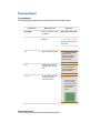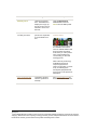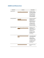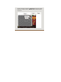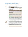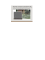
1
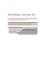
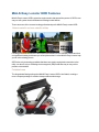
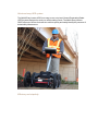
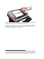
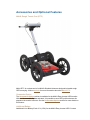
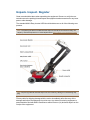
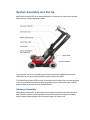
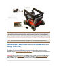
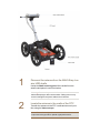
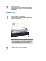
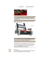
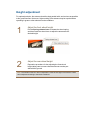
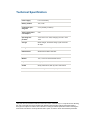
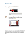
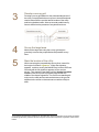
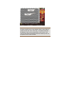
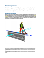
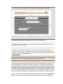
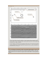
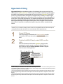
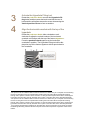
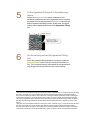
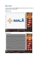
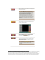
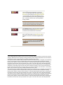
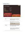
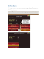
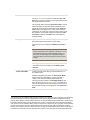
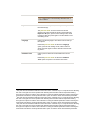
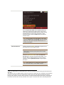
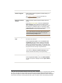
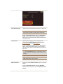
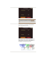
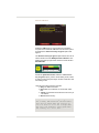
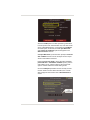
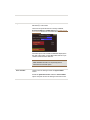
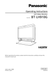
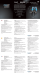
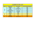
MALÅ Easy
Locator HDR
User Manual
Guide for Operating MALÅ Easy Locator HDR
Our Thanks...
Thank you for choosing MALÅ Geoscience as your Ground Penetrating Radar solution
provider.
The very core of our corporate philosophy is to provide our users with the very best -products, support and services. Our development team is committed to providing you
with the most technologically advanced and easy-to-use GPR products with the capability to meet your needs for efficiency and productivity now, and into the future.
Whether this is your first MALÅ Geoscience product, or addition to the MALÅ collection,
we believe that small investment of your time to familiarize yourself with the product by
reading this manual will be rewarded with a significant increase in productivity and satisfaction.
At MALÅ Geoscience, we welcome comments concerning the use and experience with
our products, as well as the contents and usefulness of this manual. Please address any
questions or suggestions by using the feedback channels list below.
MALÅ Geoscience team
MALÅ Easy Locator HDR User Manual
by MALÅ Geoscience
MALÅ Geoscience Press
MALÅ Geoscience
MALÅ Geoscience
Under the copyright laws, this manual may not be copied, in whole or in part, without the written consent of MALÅ
Geoscience. Your rights to the software are governed by the accompanying software license agreement.The MALÅ
Geoscience logo is a trademark of MALÅ Geoscience, registered in the Sweden and other countries.
The product described in this document is subject to continuous developments and improvements. All particulars of the
product and its use contained in this document are given by MALÅ Geoscience in good faith. However, all warranties
implied or expressed, including but not limited to implied warranties or merchantability, or fitness for purpose, are
excluded. This document is intended only to assist the reader in the use of the product and every effort has been made to
ensure that the information in this manual is accurate. MALÅ Geoscience shall not be liable for any loss or damage arising
from the use of any information in this document, or any error or omission in such information, or any incorrect use of the
product
MALÅ Geoscience, the MALÅ Geoscience logo, are trademarks of MALÅ Geoscience, registered in Sweden and other
countries. Other company and product names mentioned herein are trademarks of their respective companies. Mention
of third-party products is for informational purposes only and constitutes neither an endorsement nor a recommendation. MALÅ Geoscienceassumes no responsibility with regard to the performance or use of these products.
MALÅ Geoscience
MALÅ Geoscience AB
Skolgatan 11
SE-920 70 Malå Sweden
www.malags.com
Release Date
3/5/2013
Version
1.0
Description
Initial release
Table of Contents
Preface
About this Manual
Manual Contents
Conventions
Additional Resources
Feedback
Get Ready. Set up. Go
MALÅ Easy Locator HDR Features
Accessories and Optional Features
Unpack. Inspect. Register
Repacking and Shipping
Registering MALÅ Easy Locator HDR
System Assembly and Set Up
Hardware Assembly
Mounting MALÅ Easy Locator HDR on the optional MALA RTC (Rough Terrain Cart)
Connecting it all up
Height adjustment
Safety and Compliance
Technical Specification
Operating Instructions
Data Acquisition
Data Interpretation
Hyperbola Signatures
Detecting differing materials and sizes of features
Screenshot Option
GPS Option
Setting GPS Makers
Exporting data and Google Earth
Setting up the GPS
Hyperbola Fitting
Operating Environments
Maintenance and Troubleshooting
Equipment Maintenance
Battery maintenance and handling
Equipment handling and storage
Antenna calibration
Software updates
4
8
9
10
11
13
14
15
16
19
21
22
22
23
23
24
26
29
30
31
32
33
36
36
37
42
44
45
47
49
51
55
56
57
57
58
58
58
Monitor Software Upgrade
Troubleshooting - Frequently Answered Questions
Service and Repairs
Technical Support
User Interface
Main Display Window
Main Menu
Settings Menu
System Menu
Glossary
Index
59
60
62
63
64
65
66
70
73
83
86
Preface
The following sections contain information about this manual.
About this Manual
Manual Contents
Conventions
Additional Resources
Feedback
9
10
11
13
14
About this Manual
This manual is written for the end user of the product and explains how to set up and configure the product, as well as providing detailed instruction on its use. Basic theory for
Ground Penetration Radar is outlined to help the operator understand the underlining
technology. References for thorough discussions of this topic and applications for the
technology are also presented.
Known issues and limitations, precautions, best practices and tips are also presented so
that the most efficient and productive use can be achieved.
Manual Contents
Introduction
Information about this manual and basic introduction to Ground Penetrating Radar and its applications
Equipment Handling
Basic information regarding the handling, configuration and use of the product
Operating Instructions
Detailed information regarding the use of the
product and the interpretation of the data along with
best practice and tips
Technical Specifications
Technical specification for the product and included
accessories
Technical Support
Information for troubleshooting and gaining addition
support for the effective use of the product
Conventions
Typographical
The following typographical conventions are used in this document:
Convention
Meaning or Use
Example
Arial Bold
Menu commands or dialog labels
Draw object with frame
Warning:
Used to alert to a potential issue
Tip:
Tips and best practices
Note:
Additional information
regarding the current
topic
Example:
An example for the use
of the functionality
under discussion
Online Document
The following conventions are used in this document:
Warning: Care should
be taken when remove
this cable
Tip: Higher data precision can be
obtained if vehicle
speeds are keep
below 60 mph.
Note: The velocity
can be determined
either by Migration or
Hyperbola fitting.
E
X A M P L E
:
Th is fu n ct ion
can be u sed
t o creat e com plet e sh apes
as sh own
h ere.
Convention
Meaning or Use
Example
Glossary term1
Linked to a glossary
term. The definition is
displayed in a pop up
box when the cursor is
allowed to hover over
the term.
User the Background
removal tool to remove
noise2 from the GPR profile.
Expandable text
Content goes here
Allows title and bullet
points to be expanded
to reveal related content.
Detects metallic and nonmetallic utilities
Locating professionals know
the difficulties associated
with non-metallic utilities and
that conventional locating
tools leave you a few pieces
short. Let the MALÅ Easy
Locator help you fill in the
missing pieces.
GPR is the only technology
available that does not
require a physical connection to the utility, nor does
it rely on radiating electromagnetic (EM) fields that
may or may not be present or
detectable.
Gold, underlined text
Hyperlink to another
resource (external or
internal)
Go to www.malags.com for
the latest software download
1Example
2Typical
GPR reflection profiles contain noise and unwanted reflections that are produced by antenna
"ringing", differences in the coupling of energy with the ground, multiple reflections that occur between
the antenna and the ground surface and system and background "noise".
Additional Resources
Resource
Location
Description
GPR Training
www.malags.com/Support/Training
Information about
regularly scheduled
Ground Penetrating
Radar (GPR) training seminars at our
offices in Sweden,
USA, China, Malaysia and Australia.
GPR Applications
www.malags.com/Resources/Applications
Detailed information
about the various
applications of
Ground Penetrating
Radar across disciplines including
civil engineering,
geoscience, archeology, law enforcement and education.
GPR Case Studies
www.malags.com/Resources/CaseStudies
Database of case
studies using
Ground Penetrating
Radar in industries
including construction, mining,
homeland security,
education and
archaeology .
GPR White Paper
www.malags.com/Resources/WhitePapers
Database of technical papers dealing
with the application
of Ground Penetrating Radar in
industries including
construction, mining,
homeland security,
education and
archaeology .
GPR FAQ
www.malags.com/Support/FAQ
Knowledgebase for
Ground Penetrating
Radar.
Feedback
Feedback regarding the contents of this manual or the product may be sent using any of
the following channels.
Phone (Sweden)
+46 953 34550
Phone (USA)
+1 843 852 5021
Phone (China)
+86 108 225 0728
Phone (Malaysia)
+60 (0) 3 6250 7351
Phone (Australia)
+61 438 278 902
Web
www.malags.com/feedback
Get Ready. Set up. Go
This section walks through the steps for getting ready, setting up and basic operation of
your new MALÅ Easy Locator HDR. Information is also available on what to do in case
the equipment may have been damaged during shipment.
Note: If a defect in the equipment is discovered, make sure to contact MALÅ Geoscience prior
to use and follow the instructions for Repacking and Shipping in this section.
MALÅ Easy Locator HDR Features
Accessories and Optional Features
Unpack. Inspect. Register
System Assembly and Set Up
Height adjustment
Safety and Compliance
Technical Specification
16
19
21
23
29
30
31
MALÅ Easy Locator HDR Features
MALÅ Easy Locator HDR is precision engineered to harness all the power of GPR in one
easy-to-use system that is dedicated to locating buried utilities.
These are some of the reason locating professional prefer MALÅ Easy Locator HDR:
Detects metallic and non-metallic utilities
Locating professionals know the difficulties associated with non-metallic utilities and that
conventional locating tools leave you a few pieces short. Let the MALÅ Easy Locator help
you fill in the missing pieces.
GPR is the only technology available that does not require a physical connection to the
utility, nor does it rely on radiating electromagnetic (EM) fields that may or may not be
present or detectable.
Foldable frame
The hinged shaft design allows the MALÅ Easy Locator HDR to be folded, creating a
more compact package for efficient transportation and storage.
Quick and easy GPR system
The MALÅ Easy Locator HDR is an easy to use, entry level Ground Penetrating Radar
(GPR) system designed to meet your utility locating needs. The MALÅ Easy Locator
HDR is the tool of choice for those who need to quickly and easily identify the presence of
buried utility infrastructure.
Efficiency and simplicity
The MALÅ Easy Locator HDR as well as the user interface is designed for efficiency and
simplicity consistent with the needs of the utility locating industry.
Operation with a combined push-turn knob1 to control the program flow is unmatched
in the field in terms of simplicity. Pressing and turning the knob activates the various
menus after they are highlighted--it's that simple!
1The
push-turn knob is fitted to MALÅ monitors and acts in a similar way to a computer mouse allowing
the user to navigate menus and update data. Rotating the knob either allows sequential scrolling
through menu options to make a menu selection or changes selected parameter values. Pressing the
knob either executes the currently selected menu option or sets the value of the selected parameter.
Accessories and Optional Features
MALÅ Rough Terrain Cart (RTC)
MALA RTC is a robust carrier for MALÅ Shielded Antennas designed to handle rough
GPR surveying. Visit our website for more information about the MALA RTC.
Screenshot Option
The Screenshot Option add-on is available for the MALÅ Easy Locator HDR monitor.
With the Screenshot Option activated, it is possible to save GPR profiles that are displayed on the monitor's screen. See the Screenshot Option section for more details on
this feature.
Additional Battery
Additional Li-ion Battery Pack 12 V (3.5H) for the MALÅ Easy Locator HDR. Contact
MALÅ Geoscience for more information.
Additional Battery Charger
Additional Li-ion Battery Charger 12.6 V) for the MALÅ Easy Locator HDR. Contact
MALÅ Geoscience for more information.
Shipping case
Robust shipping case for the MALÅ Easy Locator HDR. Contact MALÅ Geoscience for
more information.
Unpack. Inspect. Register
Great care should be taken when unpacking the equipment. Be sure to verify the contents shown on the packing list and inspect the equipment and accessories for any loose
parts or other damage.
The standard MALÅ Easy Locator HDR should include some or all of the following components.
Note: The packing list that is included with the shipment should be read careful and any discrepancy should be reported to our sales department at www.malags.com/corporate/contact
Note: All packing material should be kept in the event that any damage occurred during shipping.
File any claim for shipping damage with the carrier immediately after discovery of the
damage and before the equipment is put into use. Any claims for missing equipment or
parts should be filed with MALÅ Geoscience within fourteen (14 )business days from the
receipt of the equipment.
Note: Two serial numbers are attached to the equipment, 1) on the backside of the monitor and
2) on top of the antenna under the power and GPS support.
Repacking and Shipping
The MALÅ Geoscience packing kit is specially designed for shipping MALÅ Easy Locator
HDR. The packing kit should be used whenever shipping is necessary. If original packing
materials are unavailable, pack the instrument in a wooden box that is large enough to
allow at least 80 mm of shock absorbing material to be placed all around the instrument.
This includes top, bottom and all sides.
Warning: Never use shredded fibers, paper or wood wool, as these materials tend to pack
down and permit the instrument to move inside its packing box.
Please read our shipping instructions before returning instruments to MALÅ Geoscience.
These instructions can be found on our website at www.malags.com/Support/ServiceRepairs. Contact MALÅ Geoscience for more information.
Registering MALÅ Easy Locator HDR
By registering your equipment, you ensure that you receive up-to-date documentation,
software upgrades and product information, which all helps to optimize the utilization of
the equipment and realize the maximum return on your investment.
To register your equipment, simply navigate to - www.malags.com/Support/ProductRegistration - on our website and submit the registration form.
System Assembly and Set Up
MALÅ Easy Locator HDR is an integrated system, consisting of a monitor and antenna,
linked through a single data/power cable.
The controller and other necessary electronics are built into the MALÅ Easy Locator
HDR antenna to ensure highest possible signal to noise ratio (SNR).
The MALÅ Easy Locator HDR monitor is mounted on the handle of the cart and connects
to the wheeled HDR antenna through a single data/power combination cable, and displays the data as the instrument is pushed forward.
Hardware Assembly
MALÅ Easy Locator HDR is delivered with its handles mounted on the antenna and folded.This is the most convenient position to pack and transport the equipment, and by
simply unfolding and locking the shaft locks the system is ready to use.
Tip: Changing antennas or otherwise dismounting the shaft is best accomplished with the foldable shaft in the extended up-right position. Simply insert the shafts with monitor and battery
box attached into the slots on the antenna and secure with the Shaft securing pins.
Note: The monitor can be removed from - or located on - the cart handle using two screw.
Mounting MALÅ Easy Locator HDR on the optional MALA RTC
(Rough Terrain Cart)
The MALÅ Easy Locator HDR antenna, control unit and monitor can also be used
together with the MALA Rough Terrain Cart ( RTC), which increases the operational capabilities in more rugged terrain.
Warning: Once the MALÅ Easy Locator HDRhas been mounted on the RTC and the system is
powered up, enter the Settings Menu on the monitor and set the Acquisition Parameters to
RTC Forward. This causes the wheel calibration to be changed from the internal antenna
encoder to the RTC encoder.
1
Dismount the antenna from the MALÅ Easy Locator HDR shafts
Unclip the Shaft securing pins, lift the shafts from the
antenna and place in a secure location.
Warning: Remove the power cable from the rear of the antenna
before attempting to dismount the shafts. Failing to do so may
result in damage to the power cable and connections.
2
Locate the antenna in the cradle of the RTC
Transfer the antenna to the RTC cradle and secure in position using the Velcro straps.
Note: The cradle is adjustable to ensure that the antenna is
kept close to the ground for optimal signal performance.
3
Mount the monitor
Remove the monitor from the shaft handle, transfer and
secure to the handle of the RTC using the two screws and
Velcro strips.
Connecting it all up
1
Connect cables to the monitor
Connect the longer combined power/data cable supplied
with the RTC to the monitor.
Note: Look for the countersink in the power cable and place it
towards the mark on the connection. Push lightly. If you have it
in the correct position it will go in its position smoothly. To disconnect, pull out holding the metal part of the connection.
2
Connect cables to the control unit
Connect the combined power/data to the front of the
antenna.
Note: The power cable to the rear of the antenna is connected
to the battery pack on the RTC, see Battery section below for
more information.
Finally, connect the encoder cable from the RTC wheel to
the rear of the antenna.
Note: The precision of the encoder wheel depends on several
factors, such as; the condition of measurement surface, the
pressure applied on the wheel and possible wear.
Warning: When using MALÅ Easy Locator HDR with a RTC the
wheel calibration must be changed from the internal antenna
encoder to the RTC encoder set up. Once the system is powered
up, enter the Settings Menu on the monitor and change the
Acquisition Parameters to RTC Forward.
3
Power up
Start the MALÅ Easy Locator HDR by pressing the start button on both the HDR antenna and the monitor.
To turn the antenna and monitor off, first select QUIT from
the Main Menu on the monitor, confirm the action by selecting YES then push the power button on the monitor and
release quickly. The red light will then stop blinking and the
unit will also emit a click when turning off.
Note: The antenna will automatically turn off when the monitor
is powered down.
Note: If a power cable is accidentally pulled out, the MALÅ
Easy Locator HDR components will start automatically when
reconnected.
Height adjustment
For optimal precision, the antenna should be kept parallel with, and as close as possible
to the ground surface. However, higher setting of the antenna may be required when
operating in grass or other adverse terrain conditions.
1
Adjust the front wheel height
2
Adjust the rear wheel height
Pull the Spring release lever to release the wheel spring
and then rotate the wheel lever to adjust the antenna to the
desired height.
Repeat the procedure for the adjusting the front wheel
height taking care to ensure that the antenna remains parallel with the ground.
Note: The wheels on the RTC are not adjustable. However the height of the antenna cradle
can be adjusted according to the terrain conditions.
Safety and Compliance
According to the regulations stated in ETSI EN 302 066-1 (European Telecommunication Standards Institute):
n
n
n
The control unit should not be left ON when leaving the system unintended. It should always be turned OFF when not in use.
The antennas should point towards the ground, walls etc. during measurement and not towards the air.
The antennas should be kept in close proximity to the media under
investigation.
Technical Specification
1The
Power supply
Li-ion 12V battery
Battery module
12V, 8.7Ah
Continuous Operating time
>14h (4 battery modules)
Total system power
consumption
2.4A
Operating temperature
-20 to +50 C/-4 to 122F, Charging 0 to 45C / 32 to
110F
Charger
Quick charger, automatic charge cycle 100-240V
AC input
Charge time
3h for standard battery pack
HDR Antenna
Shielded broadband 450 MHz
Environmental
IP 66
Monitor
10.4”, Color TFT Transmissive screen
Input device
Single push-turn knob1
On/Off
ON by start buttons, OFF by menu and buttons
Accessories
MALÅ Rough Terrain Cart (RTC)
push-turn knob is fitted to MALÅ monitors and acts in a similar way to a computer mouse allowing
the user to navigate menus and update data. Rotating the knob either allows sequential scrolling
through menu options to make a menu selection or changes selected parameter values. Pressing the
knob either executes the currently selected menu option or sets the value of the selected parameter.
Operating Instructions
The following sections walk you through more advanced modes of operation of the equipment giving best practices and detailed information regarding specific applications.
Data Acquisition
Data Interpretation
Screenshot Option
GPS Option
Setting GPS Makers
Exporting data and Google Earth
Setting up the GPS
Hyperbola Fitting
Operating Environments
33
36
42
44
45
47
49
51
55
Data Acquisition
1
Power up MALÅ Easy Locator HDR
Press the power buttons on the HDR Antenna and the monitor.
Note: Power indicator lamps will remain on for both the monitor
and the antenna when the power is on and the unit is functioning
correctly.
2
1The
Determine the alignment of the utility
Use push-turn knob1 to select and press the Start button,
and then make several passes of the target site to determine
the approximate location and orientation of the utility by
searching for a feature signature2.
push-turn knob is fitted to MALÅ monitors and acts in a similar way to a computer mouse allowing
the user to navigate menus and update data. Rotating the knob either allows sequential scrolling
through menu options to make a menu selection or changes selected parameter values. Pressing the
knob either executes the currently selected menu option or sets the value of the selected parameter.
2An inverted hyperbola that is displayed in the GPR data. These hyperbolas are generally caused by
the GPR signals being reflected off buried objects and therefore represent a signature of the buried
feature.
3
Develop a survey grid
4
5
Survey the target area
1An
Develop a survey grid based on the estimated alignment of
the utility. Set perpendicular survey line to be traversed and
used to determine the precise lateral location of the utility
and its longitudinal extent. Also set several parallel survey
lines to determine the presents of any lateral services.
Mark out the target site using the survey grid and progressively traverse the perpendicular and parallel survey
lines.
Mark the location of the utility
While traversing the perpendicular survey lines, search for
the begin of a feature signature1. When the signature
appears, continue moving the MALÅ Easy Locator HDR cart
forward until the full signature appears on the monitor
screen. Then move the cart back until the Vertical Location
Cursor in the GPR profile is precisely aligned with the
middle of the feature signature. The cart is now standing directly over the utility and a mark can be draw on the ground
adjacent to the arrow on the antenna to mark the utility location.
inverted hyperbola that is displayed in the GPR data. These hyperbolas are generally caused by
the GPR signals being reflected off buried objects and therefore represent a signature of the buried
feature.
Tip: The last signatures can be retained on the screen by lifting
the back wheels when moving theMALÅ Easy Locator HDR in
position for the next scan. In this way, a comparison between
the different scans can be made directly on the screen. This
can only be acheived if the GPR profiles are relatively short, as
the space on the screen is limited.
Data Interpretation
Buried utilities are displayed in the GPR profile as a hyperbola, which is often referred to
as a signature1. The shape, size and intensity of these signatures can help identify the
features that are causing the reflections. The following are examples of data interpretation based on analysis of the hyperbolic reflections.
Hyperbola Signatures
When the GPR scan is conducted perpendicular to the direction of a buried utility, the buried utility is displayed in the GPR profile as a hyperbola (point object). The hyperbola signature 2 is desirable since pinpointing the exact location and depth of the buried utility will
be easier to determine. Careful planning of the survey grid is therefore essential to obtaining accurate and reliable positioning of buried utilities
1An
inverted hyperbola that is displayed in the GPR data. These hyperbolas are generally caused by
the GPR signals being reflected off buried objects and therefore represent a signature of the buried
feature.
2An inverted hyperbola that is displayed in the GPR data. These hyperbolas are generally caused by
the GPR signals being reflected off buried objects and therefore represent a signature of the buried
feature.
Note: When the scan is parallel to the longitudinal axis, a linear feature is displayed.
Detecting differing materials and sizes of features
Warning: Even though the GPR signal, in theory, is capable of differentiating between differing
materials, qualitative estimations of material properties based on GPR data collected in a natural environment is NOT advised.
Warning: The size of a buried object can at times be estimated using the GPR data.
HOWEVER, size estimations are NOT recommended using the simplified software tools
included with theMALÅ Easy Locator HDR. Size estimations of buried objects should only be
undertaken by highly experienced GPR professionals using more advanced GPR tools. Contact
MALÅ Geoscience for more information.
DISCLAIMER: MALÅ Geoscience takes no responsibility for incorrect estimations of material
properties or the size of buried objects using MALÅ Easy Locator HDR.
The signature from a buried object, in amplitude and phase, is dependent on the contrast
in dielectric properties between the object and the surrounding material. At times, it is
therefore possible to compare the signature obtained from nearby objects (at identical
depth) and make an estimate of the material properties. Usually, but not always, the signature from a metallic object (metal pipe) will be more intense than from plastic material
(PVC pipe) or fiber optic cable buried in similar soil. This can be observed for the GPR
profile in the example below where the signature from the metallic water pipe on the right
is much stronger and sharper than the signature from the adjacent PVC pipe to the left.
The size of an object can be estimated using an advanced version of the Hyperbola fitting tool, which is not available in the simplified version of the software included with
MALÅ Easy Locator HDR. Comparing the signatures from two linear objects (e.g. pipes)
of different size (diameter) buried at exactly the same depth and scanned at exactly 90
degrees, there is likely to be a clear difference in their respective signatures.
Note: Within these limits, it is possible to determine that one object is larger/smaller than the
other, but the exact size of an object should never be estimated using MALÅ Easy Locator
HDR.
Under favorable conditions and using advanced hyperbola fitting tools, the following
examples demonstrate some of the capabilities of GPR in the hands of an experienced
user.
EXAMPLE:
T h e c on c r ete s ew er l i n e i n th e mi d d l e i s l ar g e en ou g h to l eave a s i g n atu r e f r om
b oth th e top an d th e b ottom of th e p i p e. A c l os e l ook al s o s h ow s th at th e r ad i u s of
th e s i g n atu r e i s l ar g er c omp ar ed to th e w ater p i p es to th e l ef t. T h i s i n d i c ates th at
th e ob j ec t h as a l ar g er d i ameter .
In th i s examp l e, s i g n atu r es f r om th e s i d es of th e tr en c h c an al s o b e s een . W h en a
tr en c h i s b ac kf i l l ed , c h an g es th e p r op er ti es i n th e g r ou n d - - even i f th e s ame or i g i n al mater i al i s u s ed - - c au s e GPR w ave r ef l ec ti on s of f th e i n ter f ac e b etw een th e
f i l l an d th e tr en c h s i d ew al l .
Note: As the diameter of the feature increases, the reflected signature flattens. In this way, an
estimate of the relative size of the feature can be made by inspecting the radius of the hyperbola. The reflection from the cable on the right also have a smaller radius, confirming this phenomena.
EXAMPLE:
T h e f ol l ow i n g GPR i mag e al s o i l l u s tr ates th e ef f ec t of f l atten i n g th e h yp er b ol as
w i th an i n c r eas e i n th e s i z e of th e f eatu r e. In th i s c as e, th e r ad i u s of th e h yp er b ol a f r om th e 4 " g as l i n e i s ob s er ved to b e c on s i d er ab l y s mal l er th an th e U ST s
( u n d er g r ou n d s tor ag e tan ks ) .
EXAMPLE:
T h e n ext i mag e d emon s tates th e s i g n atu r es c au s ed b y a voi d u n d er th e r oad . A
d i p i n th e r oad w as th e f i r s t i n d i c ati on th at th er e w as s ometh i n g w r on g an d th e
GPR s u r vey an d th e r es u l ti n g GPR p r of i l e r eveal s th e exi s tan c e of a voi d ab ove a
d r ai n ag e c u l ver t.
Screenshot Option
The Screenshot Option add-on is available for the MALÅ Easy Locator HDR monitor.
Using the monitor with the Screenshot Option activated, it is possible to save GPR profiles that are displayed on the monitor's screen.
See Option function under the System Menu section for information about how to activate this functionality.
1
2
3
Collect GPR data
Transverse the target area to collect a GPR data profile.
Apply filters and data cleansing
Cleanse the data by applying filters until you are satisfied
with the result.
Take a screenshot
Use the push-turn knob1 to select and press the Screenshot button.
A full-screen capture of the GPR profile is saved to memory
with the date and time stamp included on the bottom of the
image.
1The
push-turn knob is fitted to MALÅ monitors and acts in a similar way to a computer mouse allowing
the user to navigate menus and update data. Rotating the knob either allows sequential scrolling
through menu options to make a menu selection or changes selected parameter values. Pressing the
knob either executes the currently selected menu option or sets the value of the selected parameter.
4
Upload the screenshot image
Connect a USB thumb drive to the back of the monitor and
the push-turn knob to select and press the Upload
Screenshot button located under the Settings menu.
GPS Option
The GPS Option add-on is available for the MALÅ Easy Locator HDR monitor. With
with the GPS Option activated, it is possible to create GPR profiles and place makers in
the GPR data using location information acquired from the built in DGPS1 antenna or an
external GPS that is mounted and connected to the MALÅ Easy Locator HDR. This data
can then be exported and then imported into Google Earth to display the position of the
buried objects.
1Differential
GPS, uses satellites and a correction from a reference station/satellite, accuracy around ±
0.5-2 m. The available systems for the Easy Locator are currently EGNOS (Europe), WAAS (USA),
GAGAN (India) and MSAS (Japan).
Setting GPS Makers
1
Activate GPS Option and set GPS Para-
2
3
Commence GPR profile scan
menters
See Option in the System Menu section for information
about how to activate this functionality and the Setting up the
GPS section of information about setting GPS parameters.
Position the MALÅ Easy Locator HDR at the start of the
scan traverse and follow the procedure described in the
Data acquisition section to start collecting GPR profile data.
Set GPS markers
When a feature signature 1 is identified in the GPR profile
during the scan, reverse the MALÅ Easy Locator HDR cart
until the Vertical position cursor is over the feature and
use the push-turn knob2 to select and press the GPS
Marker button and insert a marker into the profile. Continue
selecting and pressing the GPS Marker button to set markers at points of interests while traversing the survey area.
Note: A green circle in the GPS precision indicator (next to
the battery indicator) indicates a high level of DGPS3 accuracy.
As the differential signal deteriorates this circle with turn yellow,
indicating a decreasing in the accuracy of the GPS data. Consult the GPS Parameter Menu section for more information on
reading the GPS precision indicator and to change the setting
for the precision ranges.
Warning: No positioning information is available when the GPS
precision indicator is either gray or red, and the coordinates are
set to zero.
EXAMPLE:
1An
inverted hyperbola that is displayed in the GPR data. These hyperbolas are generally caused by
the GPR signals being reflected off buried objects and therefore represent a signature of the buried
feature.
2The push-turn knob is fitted to MALÅ monitors and acts in a similar way to a computer mouse allowing
the user to navigate menus and update data. Rotating the knob either allows sequential scrolling
through menu options to make a menu selection or changes selected parameter values. Pressing the
knob either executes the currently selected menu option or sets the value of the selected parameter.
3Differential GPS, uses satellites and a correction from a reference station/satellite, accuracy around ±
0.5-2 m. The available systems for the Easy Locator are currently EGNOS (Europe), WAAS (USA),
GAGAN (India) and MSAS (Japan).
In th i s examp l e a f eatu r e si gn at u re h as b een d etec ted an d a mar ker w i th a Marker I D of 6 9 h as b een
i n s er ted .
Exporting data and Google Earth
1
Export data to USB thumb drive
From the Setting Menu use the push-turn knob to select
and the press the Upload GPS marker button to upload the
marker data to the USB thumb drive. See the Setting Menu
for section for more information on uploading GPS markers
to a USB thumb drive.
Note: The markers are uploaded in two file formats, one with a
*.gpm and the other with a *.kml extension. The *.gpm file is a
text file containing markers information and the *.kml file is for
use in Google Earth.
Tip: The *.gpm file contains the coordinate data in a format that
is compatible with online mapping applications, or GIS software.
Warning: Depending on the coordinate system adopted in your
country, it may be necessary to apply a transformation to the x-y
values when extracting the coordinate data from the *.gpm file. In
some cases, this may be as simple as interchanging the x and y
values
2
View data in Google Earth
Connect the thumb drive to a computer and open the marker
file with the .kml extension from Google Earth. The markers
are displayed as points on Google Earth. Further information
about the data quality and distance of the marker from the
beginning of the GPR profile is displayed in an information
bubble that appears after clicking individual marker points.
EXAMPLE:
W h en s avi n g s c r een s h ots f r om th e MAL Å E as y L oc ator
HDR mon i tor , th e mar ker s ar e s h ow n ab ove th e GPR
p r of i l e w i th a c or r es p on d i n g ID al l ow i n g th e c r os s - r ef er en c i n g an d vi ew i n g of mar ker d ata to b e mad e
b etw een th e s c r een s h ot an d Goog l e E ar th .
Setting up the GPS
1
2
Open the System Menu
See System Menu for more information about accessing
and using the System Menu..
Open the GPS Parameters Menu
Using the turn-push knob, navigate to the GPS Parameters
Menu button and press to open the menu panel.
Set the GPS parameters
Using the instruction provided in theGPS Parameters
Menusection, set the parameters for the GPS and select
and press the Save and Exit button to save the setting and
return to the Systems Menu.
Note: When using the COM port to connect to an external
GPS two more parameters, ( COM port Baud rate and CheckSum Validation), are displayed in the GPS Parameters Menu
and will need to be set also .
See the GPS Parameter Menu section for more information
about setting these parameters.
Hyperbola Fitting
Hyperbola fitting is a standard procedure for estimating the average velocity of the
GPR signal to a point reflector1. Different ground conditions (dialect properties) affect
the signal velocity and the resulting shape of the point reflector signature2 in the GPR
profile. Dry sandy soils allow the signal to propagate easily resulting in a higher signal
velocity and flatter signature than in the case of wet clay where the wave propagation is
much slower. Using this phenomenon, it is possible to estimate the signal velocity in the
ground by comparing and fitting the shape of the measured hyperbola to that of published hyperbola shape verses signal velocity data. Once the signal velocity has been
determined, it is possible to estimate the depth to the point reflector causing the signature.
Warning: The user must ensure that the scan is accurately aligned at 90 degrees to the line of
the utility. Any increase in the angle of the scan from the perpendicular will cause the shape of
the hyperbola to broaden and result in an overestimation of the signal velocity.
1
2
1Small
Start a GPR scan
Use the procedure described in the Data Acquisition section
to conduct a GRP scan across the area where a utility is located.
Position the MALÅ Easy Locator HDR over the
utility
After the full extent of the feature signature3 has been displayed on the monitor screen, reverse the MALÅ Easy Locator HDR cart until the Vertical position cursor is aligned
with the center of the hyperbola.
bodies (i.e. around the size of the radar wavelength around 0.1–10m in diameter) which have a
considerably different dielectric constant than the surrounding material. These point reflectors produce
a hyperbola signature in the GPR profile.
2An inverted hyperbola that is displayed in the GPR data. These hyperbolas are generally caused by
the GPR signals being reflected off buried objects and therefore represent a signature of the buried
feature.
3An inverted hyperbola that is displayed in the GPR data. These hyperbolas are generally caused by
the GPR signals being reflected off buried objects and therefore represent a signature of the buried
feature.
3
4
1The
Activate the Hyperbola Fitting tool
Rotate the push-turn knob1 to select the Hyperbola Fitting button and then press the knob to activate the tool. A
horizontal line will appear across the screen intersecting the
Vertical position cursor to form crosshairs.
Align the horizontal crosshair with the top of the
hyperbola
Rotate the push-turn knob2 either clockwise or anticlockwise to adjust the vertical location of the horizontal
crosshair until it aligns with the top of the feature signature3.
Press the push-turn knob again to set the horizontal
crosshairs in position. The Hyperbola Fitting tool will be displayed on top of the feature signature with its apex locked to
the crosshairs.
push-turn knob is fitted to MALÅ monitors and acts in a similar way to a computer mouse allowing
the user to navigate menus and update data. Rotating the knob either allows sequential scrolling
through menu options to make a menu selection or changes selected parameter values. Pressing the
knob either executes the currently selected menu option or sets the value of the selected parameter.
2The push-turn knob is fitted to MALÅ monitors and acts in a similar way to a computer mouse allowing
the user to navigate menus and update data. Rotating the knob either allows sequential scrolling
through menu options to make a menu selection or changes selected parameter values. Pressing the
knob either executes the currently selected menu option or sets the value of the selected parameter.
3An inverted hyperbola that is displayed in the GPR data. These hyperbolas are generally caused by
the GPR signals being reflected off buried objects and therefore represent a signature of the buried
feature.
5
Fit the Hyperbola Fitting tool to the feature sig-
6
Set the velocity and exit the Hyperbola Fitting
1The
nature
Rotate the push-turn knob1 either clockwise or anticlockwise to adjust the size of the hyperbola until its matches
the shape of the underlying feature signature2 and press the
knob to complete the fitting process. At this point, the signal
velocity will be displayed at the top of the Hyperbola Fitting
tool.
tool
When the hyperbola fitting operation is complete, press the
push-turn knob3 twice to set the velocity and exit the function. The new signal velocity value based on the hyperbola fitting will appear in the bottom left of the monitor display.
push-turn knob is fitted to MALÅ monitors and acts in a similar way to a computer mouse allowing
the user to navigate menus and update data. Rotating the knob either allows sequential scrolling
through menu options to make a menu selection or changes selected parameter values. Pressing the
knob either executes the currently selected menu option or sets the value of the selected parameter.
2An inverted hyperbola that is displayed in the GPR data. These hyperbolas are generally caused by
the GPR signals being reflected off buried objects and therefore represent a signature of the buried
feature.
3The push-turn knob is fitted to MALÅ monitors and acts in a similar way to a computer mouse allowing
the user to navigate menus and update data. Rotating the knob either allows sequential scrolling
through menu options to make a menu selection or changes selected parameter values. Pressing the
knob either executes the currently selected menu option or sets the value of the selected parameter.
Operating Environments
Range of recommended operating environments and limitations of the equipment.
Maintenance and
Troubleshooting
The following sections cover proactive maintenance that will help protect your investment
and ensure maximize your ROI.
Equipment Maintenance
Monitor Software Upgrade
Troubleshooting - Frequently Answered Questions
Service and Repairs
Technical Support
57
59
60
62
63
Equipment Maintenance
This section highlights some proactive measures that can be taken to help prolong the life
of the MALÅ Easy Locator HDR and accessories, as well as the application of software
updates and instrument calibration that ensure the maximum possible performance from
the equipment.
Battery maintenance and handling
A 12V/8.7Ah Li-ion battery is shipped with MALÅ Easy Locator HDR and is the recommended power source for the equipment. Under normal operating and handling conditions, this battery is capable of up to 3.5 hours of continuous operation. MALÅ Easy
Locator HDR will automatically turn itself off when the battery voltage drops below 10V.
A meter showing the remaining battery capacity is displayed on the monitor screen.
Tip: To maximize the life of the battery, make sure the battery is stored fully charged.
MALÅ Easy Locator HDR can also be powered by any other external 12V DC power
source.
Warning: Power sources other than the recommended 12V/8.7Ah Li-ion battery are not compatible with the power meter and the status of the battery will not be report accurately.
The battery can either be left in the battery box while charging or removed but always
turn the system off before charging the battery.
A special battery pack is provided for MALÅ Easy Locator HDR when it is used with a
RTC and this battery pack is mounted directly on the RTC handle. This battery pack also
uses a 12V/8.7Ah Li-ion battery and the maintenance and handling is the same as for the
standard MALÅ Easy Locator HDR system.
The MALÅ Easy Locator HDR battery charger is an automatic quick-charge technology
designed specifically for Li-ion batteries.
Tip: Though recharging up to 80% of the full capacity is typically very fast, it is recommended
to keep the battery charging until it is fully charged to help extend the battery life.
Note: The battery charger can be left on after the battery has been fully charged where it will
then automatically enter a maintenance charging mode.
The indicator lamp on the charger uses the following legend:
l
l
l
Red = Charged < 80%
Yellow = Charged 80-100%
Green = Maintenance charging
Tip: Always reset the internal memory of the charger by reconnecting it to the mains supply
and keep the charger connected until the indicator lamps turn off. This helps optimize the charging process.
Charging time for the 7Ah batteries is approximately 3-5 hours (80%-100%).
The temperature when charging should be within 0 to +45oC / 32 to 110oF. Do not
charge the batteries in direct sunlight or when surrounding temperatures is below freezing point.
Equipment handling and storage
MALÅ Easy Locator HDR system is like other geophysical instruments composed of a
number of electronic components that form a complete survey instrument. For proper
function it is important that the instrument is handled with care at all times.
All connectors should be kept clean and protected from dust and moisture. When finishing a survey the equipment should be checked and packed properly. Batteries should
be kept charged if possible and if stored for longer time they should be charged occasionally.
Antenna calibration
While the MALÅ Easy Locator HDR is designed to provide many years of trouble free
operation, we recommend regular maintenance to to optimize the performance of the system. Contact MALÅ Geoscience for more information.
Software updates
MALÅ Geoscience periodically releases software updates and upgrades for MALÅ Easy
Locator HDR. Installing these updates allows you to take advantage of the new features
and improvements that increase performance and system stability.
Make sure you receive information about these updates by registering your equipment
and use the information in the Software Upgrades section to install the latest software
update.
Monitor Software Upgrade
The monitor software can be upgraded by downloading the latest software from the
MALÅ Easy Locator HDR Web Page and installing onto a thumb drive.
Note: If you are unsure of the procedure or experience difficulties upgrading the software,
please contact MALÅ Geoscience support or your local authorized dealer.
1
2
3
Download software
Download the latest version of the MALÅ Easy Locator HDR
software from the MALÅ Easy Locator HDR Web Page and
unzip the contents onto the root directory of a thumb drive.
Insert thumb drive
Insert the thumb drive into the MALÅ Easy Locator HDR
monitor USB port.
Run upgrade
Select Software Upgrade option from the System Menu
screen.
Note: If a confirmation request is displayed, accept the request
by selecting YES.
The upgrade can take several minute to install and the monitor will re-boot after installation.
Warning: Make sure the batteries are fully charged before starting the software upgrade and DO NOT turn off the monitor while
the upgrade is in progress.
Troubleshooting - Frequently Answered Questions
MALÅ Easy Locator HDR has been design to be robust and reliable under adverse conditions. If you encounter a mechanical failure that cannot be fixed on site please contract
MALÅ Geoscience or your MALÅ Geoscience representative for advice.
System malfunctions
Most malfunctions are power or data communications related. Before contacting your
local MALÅ Geoscience office or authorized dealer please follow these simple steps.
1
Check battery capacity
2
Check connectors
Connect the battery to the charger and switch on the charger
at the electrical outlet.The light on the battery charger should
be either yellow or green indicating an operative charge. If
the indicator light is red, continue charging until the charging
cycle is complete, i.e., indicator light turns green.
l
l
l
l
3
Disconnect and reconnect the battery connector
in the MALÅ Easy Locator HDR battery box or
RTC battery bag.
Disconnect and reconnect the power cable connectors on the rear of the MALÅ Easy Locator
HDR battery box or RTC bag and the connector
on rear of the antenna.
Disconnect and reconnect both ends of the combined power/data cable between the antenna
and the MALÅ Easy Locator HDR monitor.
Check the pulse encoder connector on the rear
of the antenna.
Restart MALÅ Easy Locator HDR
Turn off the MALÅ Easy Locator HDR antenna and monitor,
by first selecting QUIT from the on-screen menu options on
the monitor, confirm the action by selecting YES then push
the power button on the monitor and release quickly. The red
light will then stop blinking and the unit will also emit a click
when turning off. Wait 10 seconds before switching on the
monitor and antenna.
Note: If the monitor is not responding, turn the unit off by pushing the power switch.
4
Control settings
Check the settings in the Settings Menu.
Note: Incorrect settings for the Acquisition Mode will not display updates of the location of theMALÅ Easy Locator HDR in
the GPR profile when a scan is started. Verify that the correct
option is selected.
Service and Repairs
To maintain maximum performance, MALÅ Easy Locator HDR should be regularly serviced. Contact MALÅ Geoscience or your MALÅ Geoscience representative for more
information on how to service MALÅ Easy Locator HDR.
If MALÅ Easy Locator HDR is damaged or malfunctioning, make a service request on
our website www.malags.com.
More Service and Repair options:
Frequently answered question
Service and Repairs
Technical Support
MALÅ Geoscience is committed to providing exceptional product support. Our technical
support representatives are available online to help you find answers to even the most
challenging technical support issues. Our experienced support team works very closely
with the development teams to ensure that every client receives the best possible support.
Technical support requests can be made directly from our website www.malags.com.
More support options:
Frequently answered question
Training
Software updates
Service and Repairs
User Interface
The following sections contain a detailed description of the user interface and give tips
and warning designed to help the user achieve the highest possible level of productivity
and safety while operating the MALÅ Easy Locator HDR.
Main Display Window
Main Menu
Settings Menu
System Menu
65
66
70
73
Main Display Window
The MALÅ Easy Locator HDR monitor uses dedicated software design specifically for
locating buried utilities.
Note: The monitor utilizes a Transreflective LCD display for maximum visibility in sunlight.
The screen is weather resistant (IP 66 standard) to withstand rain and dust.
The monitor is operated with a dual function push-turn knob1 for menu navigation.
Menu items are selected by rotating the knob clockwise or anti-clockwise. The selected
item is then executed by pushing the button.
Note: The monitor Main Display Window appears about 20 seconds after turning on the monitor and HDR antenna.
1The
push-turn knob is fitted to MALÅ monitors and acts in a similar way to a computer mouse allowing
the user to navigate menus and update data. Rotating the knob either allows sequential scrolling
through menu options to make a menu selection or changes selected parameter values. Pressing the
knob either executes the currently selected menu option or sets the value of the selected parameter.
Main Menu
The items available under the Main Menu vary depending whether the system is in
Stopped mode or Started mode.
Stopped mode:
Started mode:
Quit and shutdown the system after completing the
radar measurements.
Note: If the QUIT option is executed but the
monitor is not turned off immediately, the unit
has to be put through a power cycling
sequence before it can be restarted. This is
achieved pressing the power switch on the
monitor and then waiting for 5-10 seconds
before pressing the power switch again. If this
procedure is not followed, the unit will fail to
turn on.
Press the Start button to start scanning. The GPR
data will begin to appear on the black screen as
the unit is moved forward.
Press the Setting button to access the settings
menu. See the Setting Menu section for more
information on the use of this option.
The Fullscreen button toggles the display to fullscreen mode where the menu and status information is hidden and the entire display is used to
display the GPR profile.
Note: Press the push-turn knob1 again returns
the display to the default with the menu
included.
1The
push-turn knob is fitted to MALÅ monitors and acts in a similar way to a computer mouse allowing
the user to navigate menus and update data. Rotating the knob either allows sequential scrolling
through menu options to make a menu selection or changes selected parameter values. Pressing the
knob either executes the currently selected menu option or sets the value of the selected parameter.
The Background removal filter button is used to
remove horizontal lines/reflections caused by
noise 1 from the GPR profile. By rotating the pushturn knob2 various levels of background removal
3 can be applied. The affect of the filtering can be
noticed immediately and the level gradually adjusted to create the clearest and most interpretable
image possible.
Note: Going from zero to full filter setting has
the effect of progressively removing more background noise by average value calculations.
The Contrast button is used to set the contrast of
the GPR profile. Rotating the push-turn knob4
increases and decreases the contrast level.
The Time gain button is used to adjust the time
gain for the GPR profile. The push-turn knob5 is
rotated to increase or decrease the applied time
gain.
Note: When the Auto Gain option in the System Menu is selected, the manual Time gain is
deactivated and removed from the main
screen.
1Typical
GPR reflection profiles contain noise and unwanted reflections that are produced by antenna
"ringing", differences in the coupling of energy with the ground, multiple reflections that occur between
the antenna and the ground surface and system and background "noise".
2The push-turn knob is fitted to MALÅ monitors and acts in a similar way to a computer mouse allowing
the user to navigate menus and update data. Rotating the knob either allows sequential scrolling
through menu options to make a menu selection or changes selected parameter values. Pressing the
knob either executes the currently selected menu option or sets the value of the selected parameter.
3Background removal is used to remove horizontal and nearly horizontal features in the radargram by
subtracting a calculated mean trace from all traces, sample by sample. It can be useful for removing
the direct air wave (first arrival) or ringing (due to poor ground conditions) from the data. Care must be
taken in this process not to remove real linear features from the data.
4The push-turn knob is fitted to MALÅ monitors and acts in a similar way to a computer mouse allowing
the user to navigate menus and update data. Rotating the knob either allows sequential scrolling
through menu options to make a menu selection or changes selected parameter values. Pressing the
knob either executes the currently selected menu option or sets the value of the selected parameter.
5The push-turn knob is fitted to MALÅ monitors and acts in a similar way to a computer mouse allowing
the user to navigate menus and update data. Rotating the knob either allows sequential scrolling
through menu options to make a menu selection or changes selected parameter values. Pressing the
knob either executes the currently selected menu option or sets the value of the selected parameter.
Tip: Gain is very useful for making targets
appear brighter in the GPR profile, this is especially important when searching for deeper targets.
The Hyperbola fitting button is use to perform
hyperbola fitting. See Hyperbola fitting for more
information.
Note: The Hyperbola fittingbutton is only visible when in the Started mode.
The Screenshot button is used to take a screenshot of the currectly displayed GPR profile. See
Screenshot Option for more information.
Note: This option is only available if the
Screenshot Option has been activated
Sets a GPS maker in the GPR profile. See GPS
Option for more information.
Note: This option is only available if the GPS
Option has been activated.
Settings Menu
Color
Change the color scheme for the GPR profiles.
Three options are available, a gray scale and two
different color schemes.
Backlight brightness
Set the brightness to suit the ambient light conditions. This setting can be adjusted within and
range of 0-100%.
Tip: Reducing the backlight will extend the battery life between charges.
Soil Type
Set wave velocity based on soil type. Setting the
wave velocity allows the adjustment of the depth
scale for differing soil conditions.
Warning: This is a critical setting if accurate depth
information is required. Soil conditions can vary
rapidly with location and all depth information
must be used with caution.
Tip: Using the Hyperbola fitting tool is a good
way of calculating the soil type and usually
achieves the best results when estimating the
depth of a utility.
Acquisition Mode
Set the type of trigger to be used for initiating a
measurement. The trigger information is used to
establish the horizontal scale for each GPR profile.
Five triggering options are available:
l
l
l
l
l
Forward: Uses the encoder located in the
left rear wheel when the MALÅ Easy Locator
HDR cart is pushed forward. (Default setting)
IBackwards: Uses the encoder located in
the left rear wheel when the MALÅ Easy Locator HDR is pulled backwards.
RTC Forward: Uses an external encoder as
in the case when using the encoder wheel
on rough terrain cart (RTC) is pushed in the
forward direction.
RTC Backward:Uses an external encoder
as in the case when using the encoder
wheel on rough terrain cart (RTC) is pulled
in the reverse direction.
Time Triggering: Used when horizontal distance information is not available, such as in
the case of rough terrain. Measurements are
initiated at specific time intervals.
System Parameters
Select this option to open the System Menu and
apply system parameters.
Upload Screenshots
Upload GPR profile images to an USB thumb drive
connected to the monitor.
Note: This option is only available if the Screenshot Option is activated.
Upload GPS makers
Upload GPS makers to an USB thumb drive connected to the monitor.
Note: This option is only available if the GPS
Option is activated.
Save
Saves changes to the Setting Menu.
Cancel
Closes the Setting Menu without applying changes.
System Menu
The System Menu is accessed by selecting and pressing the System Parameters button in the Settings Menu.
Note: The System Menu is divided between two screens. The first screen is displayed as the
default and the second screen is accessed by selecting and pressing the NEXT SCREEN >>
button from the first screen.
Time and date
Used to set the current time and date.
The push-turn knob1 is rotated to select the Time and
date option and then pressed to enter data editing mode
and begin editing the values.
Once in data editing mode the push-turn knob is used to
select and edit the individual values of the date (year/month/day) and time (hours/minutes). Rotate push-turn
knob to move the selection to a value, press to select ,
rotate again to roll through values and press again to set
the selection. Once all the updates are made, the pushturn knob is rotated to the End button and pressed to
quite the activity.
Battery max level
Used to set the maximum battery voltage of the battery
being used with the MALÅ Easy Locator HDR.
This value is used to calibrate the Battery level indicator.
Note: Default for the Battery max level is set to 11V,
which corresponds to the maximum voltage (11.1V) of
the standard internal supplied with MALÅ Easy Locator HDR. If another type of rechargeable battery is
used, this setting must be changed to match its rated
voltage.
Warning: Incorrect settings for the Battery max level
will result in erroneous reading in the Battery level
indicator.
Power Save Mode
Used to activate power saving for the MALÅ Easy Locator HDR monitor.
Select the On option to activate the Power Save Mode.
When this mode is selected the monitor will enter a
"sleep" mode with the backlight dimmed after 30
seconds of inactivity while in the Stopped mode of operation. Movement of the push-turn knob2 revives the monitor from this "sleep" mode and subsequent movement of
the knob will result in normal operation of the push-turn
knob.
1The
push-turn knob is fitted to MALÅ monitors and acts in a similar way to a computer mouse allowing
the user to navigate menus and update data. Rotating the knob either allows sequential scrolling
through menu options to make a menu selection or changes selected parameter values. Pressing the
knob either executes the currently selected menu option or sets the value of the selected parameter.
2The push-turn knob is fitted to MALÅ monitors and acts in a similar way to a computer mouse allowing
the user to navigate menus and update data. Rotating the knob either allows sequential scrolling
through menu options to make a menu selection or changes selected parameter values. Pressing the
knob either executes the currently selected menu option or sets the value of the selected parameter.
Note: This function is automatically disabled when a
scan is started.
Imperial or SI
Used to set the unit system, either Imperial or System
International (SI) .
The push-turn knob1 is used to select and set the
desired unit system. Rotate the knob to select either the
Imperial or SI option, press to enter editing mode, rotate
to select a value and press again to set the selection and
exit editing mode.
Language
Used to set the language to be used for menus and system options.
Rotate the push-turn knob2 to select the Language
option, press to enter editing mode, rotate to select a
value and press again to set the selection and exit editing mode.
Hardware Tests
Used to perform self-tests of individual items of hardware.
Rotate the push-turn knob3 to select the Hardware
Tests option and press to access the test screen.
1The
push-turn knob is fitted to MALÅ monitors and acts in a similar way to a computer mouse allowing
the user to navigate menus and update data. Rotating the knob either allows sequential scrolling
through menu options to make a menu selection or changes selected parameter values. Pressing the
knob either executes the currently selected menu option or sets the value of the selected parameter.
2The push-turn knob is fitted to MALÅ monitors and acts in a similar way to a computer mouse allowing
the user to navigate menus and update data. Rotating the knob either allows sequential scrolling
through menu options to make a menu selection or changes selected parameter values. Pressing the
knob either executes the currently selected menu option or sets the value of the selected parameter.
3The push-turn knob is fitted to MALÅ monitors and acts in a similar way to a computer mouse allowing
the user to navigate menus and update data. Rotating the knob either allows sequential scrolling
through menu options to make a menu selection or changes selected parameter values. Pressing the
knob either executes the currently selected menu option or sets the value of the selected parameter.
Press the push-turn knob with the Start Tests button
selected to commence the testing. Each item of hardware will be tested sequentially with the results of each
tested displayed on the screen and written to a file.
Rotate the knob to select the Quit button and press to
exit this screen.
Note: These results can be uploaded to a pen drive
using the Upload "test_results.jpg" option for further
diagnosis of the system by MALÅ Geoscience or a
local representative.
Data Disk Format
Used to reformat the SSD1 radar data storage device in
the MALÅ Easy Locator HDR monitor.
Tip: It is recommended that reformatting is performed
periodically to maintain peak performance for data
management.
Rotate the push-turn knob2 to select the Data Disk
Format option and press to initiate reformatting. A confirmation dialog is displayed before commencing the
operation. Use the push-turn knob to accept or reject
this action.
Note: Reformatting does not affect the operating system or the MALÅ Easy Locator HDR software.
1SSD
is an abbreviation for Solid State Drive, which the a randon access memory device used to storage data.
2The push-turn knob is fitted to MALÅ monitors and acts in a similar way to a computer mouse allowing
the user to navigate menus and update data. Rotating the knob either allows sequential scrolling
through menu options to make a menu selection or changes selected parameter values. Pressing the
knob either executes the currently selected menu option or sets the value of the selected parameter.
Software Upgrade
Used to apply software upgrades to the MALÅ Easy Locator HDR software.
See Software Upgrades for more information on
installing these software upgrades.
Restore Predefined
Settings
Used to reset the resets the system settings within the
monitor.
Rotate the push-turn knob1 to select the Restore Predefined Settings option and press to perform a reset
when experiencing problems or if you would like to reset
the settings to a predefined state. A confirmation dialog
is displayed before reset operation is performed. Use the
push-turn knob to accept or reject this action.
Note: This restore is a low-level reset and should be
performed as the first option before executing the
Restore Factory Settings option.
Restore Factory Settings
Used to restore the the original factory settings for both
the monitor and antenna.
Rotate the push-turn knob to select the Restore Factory Settings option and press to perform a reset when
experiencing problems, or if you would like to reset the
settings to the default factory settings. A confirmation dialog is displayed before reset operation is performed. Use
the push-turn knob to accept or reject this action.
Warning: This option should only be used as a last
resort when the Restore Predefined Settings option
fails to solve the issues that you are experiencing.
NEXT SCREEN >>
Used to access the second System Menu screen.
Rotate the push-turn knob to select the NEXT SCREEN
>> option and press to display the second System Menu
screen.
1The
push-turn knob is fitted to MALÅ monitors and acts in a similar way to a computer mouse allowing
the user to navigate menus and update data. Rotating the knob either allows sequential scrolling
through menu options to make a menu selection or changes selected parameter values. Pressing the
knob either executes the currently selected menu option or sets the value of the selected parameter.
Default Start Depth
Used to set the default depth for the start of a GPR scan.
Tip: It is good practice to start with a large value and
reduce this value later by using the zoom function.
Rotate the push-turn knob to select the Default Start
Depth option, press to enter editing mode, rotate to
select a value and press again to set the selection and
exit editing mode.
Time Interval
Used to set the triggering interval for GPR measurements when Time Triggering is selected for the
Acquisition Mode in the Settings Menu.
Rotate the push-turn knob to select the Time Interval
option, press to enter editing mode, rotate to select a
value and press again to set the selection and exit editing mode.
Tip: The Time Interval option is useful when uneven
terrain compromises the effectiveness of wheel measurement.
Note: A lower value decreases the distance between
GPR profile scans and vise versa.
GPS Parameters
Used to access the GPS Parameters option to set parameters.
Rotate the push-turn knob to select the GPS Parameters option and press to open the GPS Parameters
screen.
Note: The optional GPS add-on must be activated for
this function to be operational, See the GPS Option
section of this manual for more information about feature.
GPS Interface/Unit
Used to set the interface type for the GPS unit connected
to the MALÅ Easy Locator HDR. Currently, the three
types of supported GPS units are:
Built-in DGPS
When the Built-in option is selected, the differential correction signal can be received in certain regions
enabling better accuracy for the positioned GPS markers. Select the correct region for your area.
External USB GPS
Select the USB option to use positioning information
acquired via an external USB GPS unit. Once this option
is selected, the Select accuracy for green option will
appear.
The Select accuracy for green option allows the user to
set the tolerance for the GPS precision indicator that is
displayed at the top right of the monitor's screen while in
Started mode.
Rotate the push-turn knob to select the Select accuracy for green option, press to enter editing mode, rotate
to select a value and press again to set the selection and
exit editing mode.
Legend for the GPS precision indicator:
l Gray: No GPS connected
l Red: GPS connected but no contact with satellites
l Yellow: Coordinates are received but accuracy is
1-20 meters
l Green: Best accuracy
Example: If Select accuracy for green is
set to DGPS, RTK Fix/Float the GPS indicator will be green when the accuracy is
0.5 m or less. If it is set to High (RTK
Fix only) the indicator turns green when
the accuracy is 2 cm or less.
External GPS via the COM port
Select the COM option to enable positioning information
to be acquired via an external GPS unit, such as the RTK
survey grade GPS antenna, connected to the COM port.
Once this option is selected, the Com port Baud rate
and Checksum validation options will appear in the
GPS Parameters acreen.
Com port Baud rate (communication speed) and CheckSum validation must be set to correspond to the output
values of the attached antenna.
Rotate the push-turn knob to select the either the Com
port Baud rate or CheckSum validation option, press to
enter editing mode, rotate to select a value and press
again to set the selection and exit editing mode.
Once the COM port parameter are set correctly and the
monitor starts to receive GPS information, the coordinates will appear at the bottom of the GPS Parameters
screen.
Option
Used to register and activate optional features in the
MALÅ Easy Locator HDR.
There are two optional features currently available,
Screenshot Option and GPS Option. See Features and
Accessories section for more information.
Activated options are identified with Active displayed to
the right of the option. Contact MALÅ Geoscience to purchase and activate these features.
Note: The Serial number of Antenna Unit and Firmware version information is required by MALÅ
Geoscience to activate option.
Save and Exit
Used to save the setting and exit the System Menu
screen.
Rotate the push-turn knob to select the Save and Exit
option and press to save the setting and exit the screen.
Glossary
A
Auto-Gain
Similar to Time-Gain except the software decides the coefficients to be applied to give a
response across the depth range without over amplifying the trace.
B
background removal
Background removal is used to remove horizontal and nearly horizontal features in the
radargram by subtracting a calculated mean trace from all traces, sample by sample. It
can be useful for removing the direct air wave (first arrival) or ringing (due to poor ground
conditions) from the data. Care must be taken in this process not to remove real linear
features from the data.
D
DGPS
Differential GPS, uses satellites and a correction from a reference station/satellite,
accuracy around ± 0.5-2 m. The available systems for the Easy Locator are currently
EGNOS (Europe), WAAS (USA), GAGAN (India) and MSAS (Japan).
Differential GPS (DGPS)
Differential GPS, uses satellites and a correction from a reference station/satellite,
accuracy around ± 0.5-2 m. The available systems for the Easy Locator are currently
EGNOS (Europe), WAAS (USA), GAGAN (India) and MSAS (Japan).
G
Glossary term
Example
GPR profile
Individual line of GPR data represented in a cross-sectional (profile) view of the subsurface.
Ground Penetrating Radar
Geophysical method that uses radar pulses to image the subsurface
H
hyperbola
The type of reflection often associated with a round object or a utility, especially when
the angle (profile) of the radar is at 90 degrees to the utility. It is a distinctive “n” shaped
reflection.
N
noise
Typical GPR reflection profiles contain noise and unwanted reflections that are produced by antenna "ringing", differences in the coupling of energy with the ground, multiple reflections that occur between the antenna and the ground surface and system and
background "noise".
P
point reflector
Small bodies (i.e. around the size of the radar wavelength around 0.1–10m in diameter)
which have a considerably different dielectric constant than the surrounding material.
These point reflectors produce a hyperbola signature in the GPR profile.
push-turn knob
The push-turn knob is fitted to MALÅ monitors and acts in a similar way to a computer
mouse allowing the user to navigate menus and update data. Rotating the knob either
allows sequential scrolling through menu options to make a menu selection or changes
selected parameter values. Pressing the knob either executes the currently selected
menu option or sets the value of the selected parameter.
R
Real Time Kinematic GPS (RTK GPS)
Real Time Kinematic GPS is expensive, uses two GPS receivers (one stationary base
and one rover) and a correction signal from the base antenna. The accuracy is around ±
1-2 cm. Network RTK also available in many locations, where the correction is received
via GSM.
S
signature
An inverted hyperbola that is displayed in the GPR data. These hyperbolas are generally
caused by the GPR signals being reflected off buried objects and therefore represent a
signature of the buried feature.
SSD
SSD is an abbreviation for Solid State Drive, which the a randon access memory device
used to storage data.
Standard GPS
Relatively inexpensive GPS that only uses satellites for positioning, These systems
generally have an accuracy around ± 4 m and are suitable for large scale layer mapping
projects.
T
Time-Gain
Time-Gain applies a time-varying gain to compensate for amplitude loss due to spreading and attenuation. The trace is multiplied by a gain function combining linear and an
exponential gain, with coefficients set by the user.
trace
A "trace" is a single, vertical column of GPR data, representing the signal "traced" by a
radar pulse as it travels from the instrument into the subsurface. Each trace is composed of individual "samples," the smallest measurement unit in the vertical dimension.
Because of geometrical "spreading," the radar signal decreases in strength with depth
as 1/r2, where r is depth.
Index
F
Filtering
Migration 11
G
Ground Penetrating Radar 3, 12-13, 16, 34, 36, 42, 44, 51, 61, 67, 70, 78
H
Hyperbola fitting 37, 51, 69, 71
T
typographical 11