1
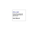
PDC-170
Panel Display Consult with 17”
color TFT/LCD Medical Display
User Manual
Copyright
This document is copyrighted, © 2004. All rights are reserved. The original manufacturer reserves the right to make improvements to the products
described in this manual at any time without notice.
No part of this manual may be reproduced, copied, translated or transmitted in any form or by any means without the prior written permission of
the original manufacturer. Information provided in this manual is
intended to be accurate and reliable. However, the original manufacturer
assumes no responsibility for its use, nor for any infringements upon the
rights of third parties that may result from such use.
Acknowledgements
Elo and AccuTouch are trademarks of Elo TouchSystems Inc.
Windows is a registered trademark of Microsoft Corporation.
All other trademarks, product names or logos are the property of their
respective owners.
For more information on this and other Advantech products, please visit
our websites at:
http://www.advantech.com
http://www.advantech.com/ppc
For technical support and service, please visit our support website at:
http://support.advantech.com
Part No. 2000000046
1st Edition, Printed in Taiwan, March. 2004
PDC-170 User Manual
ii
FCC Class B
This equipment has been tested and found to comply with the limits for a
Class B digital device, pursuant to Part 15 of the FCC Rules. These limits
are designed to provide reasonable protection against harmful interference when the equipment is operated in a residential environment. This
equipment generates, uses and can radiate radio frequency energy. If not
installed and used in accordance with this user's manual, it may cause
harmful interference to radio communications. Note that even when this
equipment is installed and used in accordance with this user's manual,
there is still no guarantee that interference will not occur. If this equipment is believed to be causing harmful interference to radio or television
reception, this can be determined by turning the equipment on and off. If
interference is occurring, the user is encouraged to try to correct the interference by one or more of the following measures:
• Reorient or relocate the receiving antenna
• Increase the separation between the equipment and the receiver
• Connect the equipment to a power outlet on a circuit different from that
to which the receiver is connected
• Consult the dealer or an experienced radio/TV technician for help
Warning!
Any changes or modifications made to the
equipment which are not expressly approved by
the relevant standards authority could void your
authority to operate the equipment.
1. Input voltage rated 12 VDC, 3.33 A
2. Packing: please carry the unit with both
hands, handle with care.
3. Maintenance: to properly maintain and clean
the surfaces, use only approved products or
clean with a dry applicator.
iii
Packing List
Before installing your medical display, ensure that the following materials have been received:
• PDC-170 series Medical display
• AC/DC adapter
• Accessories for PDC-170
• COM port cable (1.8 m) for touch screen
• Power cord (1.8 m) - USA type (other types are available by request)
• DVI cable (1.8 m)
• USB cable (1.8m) for host to hub
• Audio cable (1.5 m)
• "Drivers and Utilities" CD-ROM (user manual inside)
If any of these items are missing or damaged, contact your distributor or
sales representative immediately.
Additional Information and Assistance
1.
Visit the Advantech web site at www.advantech.com where you
can find the latest information about the product.
2.
Contact your distributor, sales representative, or Advantech's customer service center for technical support if you need additional
assistance. Please have the following information ready before you
call:
• Product name and serial number
• Description of your peripheral attachments
• Description of your software (operating system, version, application
software, etc.)
• A complete description of the problem
• The exact wording of any error messages
PDC-170 User Manual
iv
Safety Instructions
1. Read these safety instructions carefully.
2. Keep this User's Manual for later reference.
3. Disconnect this equipment from any AC outlet before cleaning. Use a damp
cloth. Do not use liquid or spray detergents for cleaning.
4. For plug-in equipment, the power outlet socket must be located near the
equipment and must be easily accessible.
5. Keep this equipment away from humidity.
6. Put this equipment on a reliable surface during installation. Dropping it or letting it fall may cause damage.
7. The openings on the enclosure are for air convection. Protect the equipment
from overheating. DO NOT COVER THE OPENINGS.
8. Make sure the voltage of the power source is correct before connecting the
equipment to the power outlet.
9. Position the power cord so that people cannot step on it. Do not place anything
over the power cord.
10. All cautions and warnings on the equipment should be noted.
11. If the equipment is not used for a long time, disconnect it from the power
source to avoid damage by transient overvoltage.
12. Never pour any liquid into an opening. This may cause fire or electrical shock.
13. Never open the equipment. For safety reasons, the equipment should be
opened only by qualified service personnel.
14. If one of the following situations arises, get the equipment checked by service
personnel:
a. The power cord or plug is damaged.
b. Liquid has penetrated into the equipment.
c. The equipment has been exposed to moisture.
d. The equipment does not work well, or you cannot get it to work according
to the user's manual.
e. The equipment has been dropped and damaged.
f. The equipment has obvious signs of breakage.
15. DO NOT LEAVE THIS EQUIPMENT IN AN ENVIRONMENT WHERE
THE STORAGE TEMPERATURE MAY GO BELOW -20° C (-4° F) OR
ABOVE 60° C (140° F). THIS COULD DAMAGE THE EQUIPMENT. THE
EQUIPMENT SHOULD BE IN A CONTROLLED ENVIRONMENT.
16. CAUTION: DANGER OF EXPLOSION IF BATTERY IS INCORRECTLY
REPLACED.REPLACE ONLY WITH THE SAME OR EQUIVALENT
TYPE RECOMMENDED BY THE MANUFACTURER, DISCARD USED
BATTERIES ACCORDING TO THE MANUFACTURER'S INSTRUCTIONS.
17. CLASSIFICATION:
- Supplied with Class I adaptor
- No applied part
- IPX1
- Continuous Operation
v
- No AP or APG category
18. Disconnect device: Appliance inlet.
19. Follow your national requirements when disposing the unit.
20. For connection to the mains, use an approved power cord. For current up to 6
A and an appliance that weighs more than 3kg, the power cord should not be
less than H05VV-F, 3G, 0.75mm².
The sound pressure level at the operator's position according to IEC 704-1:1982 is
no more than 70 dB (A).
DISCLAIMER: This set of instructions is given according to IEC 704-1. Advantech disclaims all responsibility for the accuracy of any statements contained
herein.
PDC-170 User Manual
vi
Wichtige Sicherheishinweise
1. Bitte lesen sie Sich diese Hinweise sorgfältig durch.
2. Heben Sie diese Anleitung für den späteren Gebrauch auf.
3. Vor jedem Reinigen ist das Gerät vom Stromnetz zu trennen. Verwenden Sie
Keine Flüssig-oder Aerosolreiniger. Am besten dient ein angefeuchtetes Tuch
zur Reinigung.
4. Die NetzanschluBsteckdose soll nahe dem Gerät angebracht und leicht
zugänglich sein.
5. Das Gerät ist vor Feuchtigkeit zu schützen.
6. Bei der Aufstellung des Gerätes ist auf sicheren Stand zu achten. Ein Kippen
oder Fallen könnte Verletzungen hervorrufen.
7. Die Belüftungsöffnungen dienen zur Luftzirkulation die das Gerät vor überhitzung schützt. Sorgen Sie dafür, daB diese Öffnungen nicht abgedeckt werden.
8. Beachten Sie beim. AnschluB an das Stromnetz die AnschluBwerte.
9. Verlegen Sie die NetzanschluBleitung so, daB niemand darüber fallen kann.
Es sollte auch nichts auf der Leitung abgestellt werden.
10. Alle Hinweise und Warnungen die sich am Geräten befinden sind zu
beachten.
11. Wird das Gerät über einen längeren Zeitraum nicht benutzt, sollten Sie es vom
Stromnetz trennen. Somit wird im Falle einer Überspannung eine Beschädigung vermieden.
12. Durch die Lüftungsöffnungen dürfen niemals Gegenstände oder Flüssigkeiten
in das Gerät gelangen. Dies könnte einen Brand bzw. elektrischen Schlag auslösen.
13. Öffnen Sie niemals das Gerät. Das Gerät darf aus Gründen der elektrischen
Sicherheit nur von authorisiertem Servicepersonal geöffnet werden.
14. Wenn folgende Situationen auftreten ist das Gerät vom Stromnetz zu trennen
und von einer qualifizierten Servicestelle zu überprüfen:
a - Netzkabel oder Netzstecker sind beschädigt.
b - Flüssigkeit ist in das Gerät eingedrungen.
c - Das Gerät war Feuchtigkeit ausgesetzt.
d - Wenn das Gerät nicht der Bedienungsanleitung entsprechend funktioniert
oder Sie mit Hilfe dieser Anleitung keine Verbesserung erzielen.
e - Das Gerät ist gefallen und/oder das Gehäuse ist beschädigt.
f - Wenn das Gerät deutliche Anzeichen eines Defektes aufweist.
15. VOSICHT: Explisionsgefahr bei unsachgemaben Austausch der Batterie.Ersatz nur durch densellben order einem vom Hersteller empfohlenemahnlichen Typ. Entsorgung gebrauchter Batterien navh Angaben des
Herstellers.
Der arbeitsplatzbezogene Schalldruckpegel nach DIN 45 635 Teil 1000
beträgt 70dB(A) oder weiger.
DISCLAIMER: This set of instructions is given according to IEC704-1.
Advantech disclaims all responsibility for the accuracy of any statements
contained herein.
vii
PDC-170 User Manual
viii
Contents
Chapter
1 General Information ....................................... 2
1.1
1.2
1.3
1.4
Introduction ......................................................................
Specifications ...................................................................
Connectors........................................................................
Dimensions.......................................................................
2
3
4
6
Figure 1.1:Dimensions of PDC-170 .............................. 6
Chapter
2 System Setup.................................................... 8
2.1
A Quick Tour of the PDC-170 ......................................... 8
Figure 2.1:Front view of PDC-170 ............................... 8
Figure 2.2:Rear view of the PDC-170 ........................... 9
2.2
2.3
Preparing for first-time use .............................................. 9
Installation procedure..................................................... 10
2.3.1
2.3.2
2.3.3
2.3.4
2.4
Connecting the Power Cord ......................................... 10
Connecting the VGA Port ............................................ 10
Connecting the DVI Port ............................................. 10
Switch On the Power ................................................... 10
VESA Mounting............................................................. 10
Appendix A Touch Screen Driver Installation ................ 12
A.1
A.2
A.3
Introduction .................................................................... 12
Touch Screen Specifications .......................................... 12
A.2.1
A.2.2
A.2.3
Mechanical ................................................................... 12
Optical Light Transmission ......................................... 13
Environmental Specifications ...................................... 13
A.3.1
A.3.2
A.3.3
Installation for Windows 98/ME ................................. 14
Installation for Windows 2000 .................................... 16
Installation for Windows XP ....................................... 19
Installation of Touch Screen Driver............................ 14
Appendix B OSD Selection ................................................ 24
B.1
B.2
B.3
B.4
B.5
B.6
B.7
B.8
Introduction ....................................................................
Menu...............................................................................
Auto Adjust ....................................................................
Input select .....................................................................
Brightness-Contrast........................................................
Color...............................................................................
Image..............................................................................
Tools...............................................................................
ix
24
24
24
25
25
26
26
27
Table of Contents
PDC-170 User Manual
x
CHAPTER
1
2
General Information
This chapter provides background
information on the PDC-170.
Sections include:
• Introduction
• Specifications
• Connectors
• Dimensions
Chapter 1 General Information
1.1 Introduction
The PDC-170 panel display console is a medical grade display that is
designed to serve as a human machine interface (HMI) and as a desktop
monitor. The monitor has high brightness and contrast ratio, a 17" color
TFT LCD screen. It is also equipped with an audio line-in, two USB 2.0
hub ports, a COM port for touch screen, a DVI input port, and one VGA
input port.
The PDC-170 is a compact and user-friendly medical display. Unlike
other displays, the PDC-170 is designed to be more durable and versatile.
The display can be placed on a desktop to replace the traditional desktop
and medical monitors. In addition, its "fit anywhere" design makes it very
flexible so that it can be used in many different kinds of installations.
For system integrators, this simple, complete, compact and highly integrated display lets you easily include this display with your applications.
Common medical applications include Hospital Information Systems
(HIS), Picture Archiving and Communication Systems (PACS), Clinical
Information Systems (CIS), and Peri-Operative Information Systems
(PIS). It is also suitable for many non-medical applications, including
interactive kiosk systems, entertainment management systems, and car
park automation. The display is a reliable, cost-effective solution to your
application's processing requirements.
PDC-170 User Manual
2
1.2 Specifications
General
• Construction: PC/ABS and TPU chassis
• Dimensions (WxHxD):437 x 377 x 84 mm (17.5” × 15.0” × 3.4”)
• Weight:
6 kg (13.3 lb)
• Control: OSD
• Front Panel: IP65 rating (dust tight and protected against water jets)
Touch Screen (optional)
• Type:
5 wire, analog resistive
• Touch Point Density: 4096 x 4096(Base on controller resolution)
• Light Transmission: 75% (surface meet ASTM-D-3362-92A standard)
• Controller: RS-232 interface
• Power Consumption: +5V@200mA
LCD Specifications
• Display Type: SXGA TFT LCD
• Display Size: 17”
• Max Color: 262K colors
• Max Resolution: 1280 x 1024
• Dot Pitch: 0.264 x 0.264
• Viewing Angle:160 degrees
• Luminance: 260 cd/m2
• Contrast Ratio: 400:1
• Backlight: 4 cold cathode fluorescent lamps (replaceable)
• Lamp Lifetime: 30,000 hrs.
3
Chapter 1
Power Consumption
• Max. Output Power: 50 Watts
• AC Input Voltage: 90~264 Vac.
• Output Voltage: [email protected] A
Environment
• Storage Temperature: -20 ~ 60 ° C
• Operating Temp:0 ~ 50 °C
• Relative Humidity: 10 ~ 95% @ 40 oC (non-condensing)
• Shock:
30 G peak acceleration (11 msec duration)
• Power MTBF: 100,000 hrs
• Certificates:
EMC:
CE Class B, FCC Class B, BSMI
SAFETY: EN60601-1, UL60601-1, EN60950, UL60950
1.3 Connectors
The following connectors are situated on the left hand side of the PDC170 Series:
VGA Port (DB-15)
This DB-15 connector can be connected to the system via the external 15pin DB-15 connector located on the right side of the system unit.
DVI Port
This DVI connector is a DVI input port that can be connected to the system via the external DVI connector located on the right side of the system
unit.
PDC-170 User Manual
4
USB Ports
There is one USB2.0 input that can accept signals from an external, standard PC via the type A connector of PDC-170. The PDC-170 provides
two USB 2.0 hub functions via two type B ports.
Audio Port
PDC-170 supports one audio line-in port located in the middle left side
for speaker outputs.
Touch screen Connector (DB-9) (optional)
This connector will only be present if a touch screen is installed, and it
must be connected to the RS-232 port of the PC. The touch screen cable is
included with all orders where the touch screen option has been chosen.
DC 12V Power In
This connector will be connected to the DC 12V Switching Power Supply.
Extended Cable Transmission (optional)
A 5/20/30/50-meter VGA cable is provided for special applications.
Another longer cable is also available. For more detailed information,
please contact our dealers.
5
Chapter 1
1.4 Dimensions
Aut o
M
Figure 1.1: Dimensions of PDC-170
PDC-170 User Manual
6
CHAPTER
2
2
System Setup
This chapter provides information on
how to get started with PDC-170.
Sections include:
• Quick view of PDC-170
• Preparing for First-time Use
• Installation Procedures
• VESA mounting
Chapter 2 System Setup
2.1 A Quick Tour of the PDC-170
Before you start to set up the PDC-170, take a moment to become familiar with the locations and purposes of the controls, drives, connectors and
ports, which are illustrated in the figures below. When you place the
PDC-170 upright on the desktop, its front panel appears as shown in Figure 2-1.
Aut o
M
Auto Configuration
Trim Knob for Up and Down Hotkey
Menu, Select and Set
Right and Left Key for OSD
Power LED (Green)
Figure 2.1: Front view of PDC-170
The Power LED in the front bezel indicates the power on and off status.
When PDC-170 is powered, the LED will show in green color, and when
power is off, the LED won't have any color or light.
The Trim Knob is a kind of hot-key that can be used as a mouse or keyboard to execute programs.
PDC-170 User Manual
8
When you turn the panel PC around and look at its rear cover, you will
find the sunken I/O section is at the bottom of the PDC-170, as shown in
Fig. 2-2. (The I/O section includes various I/O ports, including the VGA
port, the DVI port, serial ports, USB ports, the line-in jack, and the power
switch.)
VGA Port
DVI Connector
COM Ports
Power Switch
USB Ports
DC Inlet
Figure 2.2: Rear view of the PDC-170
2.2 Preparing for first-time use
Before you start to set up the panel PC system, you should have the following items ready:
• Power adapter (in the accessory box)
• Power cord (in the accessory box)
• VGA or DVI cables (in the accessory box)
9
Chapter 2
2.3 Installation procedure
2.3.1 Connecting the Power Cord
The PDC-170 can only be powered by an AC/DC power adapter (90 ~
264 volts, 50 ~ 60 Hz). Be sure to always handle the power cords by holding the plug ends only. Follow these procedures in order:
1.
Connect the female end of the power cord to the AC inlet of the
power adapter.
2.
Connect the DC plug of the power adapter to PDC-170.
2.3.2 Connecting the VGA Port
Connect the VGA port on the I/O section of the PDC-170.
Note: When using the VGA port, please disconnect the DVI connector.
2.3.3 Connecting the DVI Port
Connect the DVI port on the I/O section of the PDC-170.
Note: When using the DVI port, please disconnect the VGA connector
2.3.4 Switch On the Power
Switch on the power switch on the rear cover.
2.4 VESA Mounting
The PDC-170 provides standard VESA mounting (75 x 75 x 100 x 100
mm) to help system integrators conveniently integrate the panel PC into
their system.
PDC-170 User Manual
10
A
Appendix
2
Touch Screen Driver
Installation
This chapter provides information on
the VGA setup.
Sections include:
• Introduction
• Specification
• Installation for:
- Windows 98/ME
- Windows 2000
- Windows XP
Appendix A Touch Screen Driver Installation
A.1 Introduction
The PDC-170 Series’ optional touch screen uses advanced 5-wire resistive technology. This provides more accurate sensing capacity than other
touch screen technologies. The touch screen is specially designed for
tough environments, and complies with FCC Class B standards for use in
homes and offices.
A.2 Touch Screen Specifications
A.2.1 Mechanical
Construction:
Top: Polyester with outside hard-surface coating with clear or antiglare
finish.
Inside: Transparent conductive coating.
Bottom: Glass substrate with uniform conductive coating.
Top and bottom layers are separated by patented separator dots.
Cable and Connector:
Typically a ribbon/flex cable exiting from side, with five position 0.025inch (0.635 mm) square post receptacle (AMP86015-1) termination standard AMP 87499-9 housing with 0.100-inch (2.54 mm) centers.
Positional Accuracy:
Standard deviation of error is less than ± 0.080-inch (2 mm).
Resolution:
More than 100,000 touchpoints/in² (15,500 touchpoints/cm²) for a 13inch touch screen when used with Elo controllers.
PDC-170 User Manual
12
Touch Activation Force:
Typically 2 to 4 ounces (57 to 113 g).
Surface Durability:
Surface meets Taber Abrasion Test (ASTM D 1044), CS-10F wheel,
500g.
Expected Life Performance:
The AccuTouch technology has been operationally tested to more than 35
million touches in one location without failure using a stylus similar to a
finger.
Sealing:
Unit can be sealed to meet NEMA requirements. Gasket or sealant can
make contact with the inactive border region of the touch screen.
A.2.2 Optical Light Transmission
Typically 75% over visible light spectrum, per ASTM D 1003. Optimized
for flat panel displays.
A.2.3 Environmental Specifications
Operating Temperature: -10 ~ 50° C.
Storage Temperature: -40 ~ 71° C.
Relative Humidity: Based on 24-hour period, non-condensing humidity.
Operating: 90% RH at 35° C.
Storage: 90% RH at 35° C.
Chemical Resistance
The active area of the touch screen is resistant to the following chemicals
when exposed for a period of one hour at a temperature of 70°F (21°C):
• Acetone, Ammonia-based glass cleaners, Common foods and beverages, Hexane, Isopropyl alcohol, Methylene chloride, Methyl ethyl
ketone, Mineral spirits, Turpentine
13
Appendix A
A.3 Installation of Touch Screen Driver
The touch screen driver for Windows contains a native, 32-bit driver and
a 32-bit control panel program. To facilitate installation of the touch
screen driver, you should read the instructions in this section carefully
before you attempt installation.
Note
The following windows illustrations are examples only. You must follow the flow chart
instructions and pay attention to the instructions that appear on your screen.
A.3.1 Installation for Windows 98/ME
1.
a. Select "Start", "Run”
b. Type the path “D:\PDC-170\Touchscreen\Windows98Me\Driver\Setup.exe”
c. Click “OK”
2.
Click “Yes”
PDC-170 User Manual
14
3.
Select "Smart serial controller in COM4". Then press the "OK"
button.
4.
Press "Yes" to restart your PDC-170.
5.
After re-boot, please click the target point to calibrate your touch
screen.
15
Appendix A
A.3.2 Installation for Windows 2000
1.
a. Select "Start", "Run”
b. Type the path
D:\PDC-170\Touchscreen\Windows2k\Driver\Setup.exe
c. Click “OK”
2.
Click “Next”
PDC-170 User Manual
16
3.
Click "Yes".
4.
Click "Yes" to accept the agreement.
5.
Select' COM4, then press "Next".
17
Appendix A
6.
Press "Finish" then select "Yes" to restart your PDC-170.
7.
After reboot, calibrate the touch screen.
PDC-170 User Manual
18
A.3.3 Installation for Windows XP
To install the software to your computer, you must have Windows 2000
or XP running. If you have an older version PenMount Windows 2000
driver installed in your system, please remove it first. Follow the steps
below to install the PenMount Windows 2000/XP driver
1.
Please note that the installation procedures will be different,
depending on different computer systems. If your screen shows the
following display, select ”Install from a list or specific location
(Advanced)” and press ‘Next’ and go to Step 5 to continue the
installation.
2.
If your screen’s message is not shown as Fig. 1, then from “Start”,
select “Control Panel”, select “System”, select “Hardware”, select
“Device Manager”, then double click the “Unknown device”
19
Appendix A
3.
The next screen you should see is shown below. Select “Driver”,
then ”Reinstall Driver”
4.
Select “Install from a list or specific location (Advanced)”, and
click ”Next”
PDC-170 User Manual
20
5.
Insert the PDC-170 drivers, select ”Search for best driver in these
locations” and choose ”Include this location in the search”, and
click ‘Next”
6.
The installation is finished. Click ”Finish”
21
Appendix A
7.
The screen will now show “Elo series touch and Elo touch” under
“Mice and other pointing devices” as shown below if your installation was successful. Otherwise, you need to go back to Step 1 to
Step 6 to reinstall the driver again.
8.
After the system reboots, your touch system should be working.
Please calibrate at this time.
PDC-170 User Manual
22
B
Appendix
2
OSD Selections
This chapter provides information on
the OSD Selections.
Sections include:
• Introduction
• Menu
• Auto Adjust
• Input Select
• Brightness – Contrast
• Color
• Image
• Tools
Appendix B OSD Selection
B.1 Introduction
The following images will appear on the screen when pressing the SEL
(SELECT) key. Adjust each value by pushing the UP and DOWN keys.
B.2 Menu
Each selected value is stored into LCD memory after SEL (SELECT) signal input or time out. The stored values are not affected by the power
being turned off, but the selected value is not available if the selected
mode is changed before time-out, or power is turned off before time-out.
The brightness value can’t be stored while the variable volume resistor is
selected.
This function does not work while in save mode.
800x600 60.3Hz
Input Select
1
2
B.3 Auto Adjust
You can press the auto adjust key to automatically adjust the clock frequency and x, y position settings.
PDC-170 User Manual
24
B.4 Input select
Select video signal input source from VGA or DVI. Item 1 is VGA analog input and item 2 is DVI input.
800x600 60.3Hz
Input Select
1
2
B.5 Brightness-Contrast
Adjust the brightness and contrast level of backlight control as needed.
There are three adjustments: Brightness, Contrast and Backlight Strength.
800x600 60.3Hz
Brightness - Contrast
25
Appendix B
B.6 Color
To adjust the color video performance, there are two functions to adjust:
Auto-configuration and Color Temperature.
800X600 60.3Hz
Color
B.7 Image
You can choose the following items to adjust the image performance on
the OSD: Image Width, Image Phase, Image H-Position, Image V-Position and Sharpness.
800X600 60.3Hz
Image
A
A
PDC-170 User Manual
26
B.8 Tools
In this menu item, there are two functions that can be selected and
adjusted:
• OSD: Including OSD time out, OSD Position and OSD size.
• Factory reset: Choose reset to get factory default values.
800X600 60.3Hz
Tools
27
Appendix B
PDC-170 User Manual
28