1
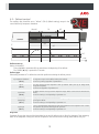
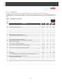
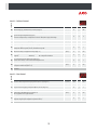
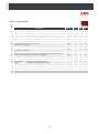
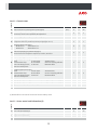
Level 2
Level 1.- General status
Description
Values
Min
Def
Max.
(min.)
0
0
99
0
0
2
P4 Selection of type of inputs: 1=1probe 2=2 probes (Page 7)
1
1
2
P5 MODBUS address (only systems with built-in communications)
1
1
99
P6 Configuration of AUX relay: 1=Defrost; 2=Alarm; 3=Light (Pages 10 to 15)
0
1
3
Temperature display mode (Page 7)
0= Whole in ºC
1=One decimal in ºC
P7
2=Whole in ºF
3=One decimal in ºF
0
1
3
0
1
2
0
0
1
P1 Daley of all functions on receiving electrical power (Page 8)
P2
P8
Access code (password) functions (Page 8)
0= Inactive; 1= Block access to parameters; 2= Keyboard lock
Probe to be displayed (as per parameter P4) (Page 7)
0=Visualization of all the probes in sequence; 1=Probe 1; 2=Probe 2
P9 Selection of probe type 0=NTC; 1=PTC (Page 7)
Configuring digital input 1 (Page 7)
0=Off
1=Door contact
4=Slave defrost
PA 3=Severe external alarm
6=Act. Fast Freezing (If C9 ¹0) 7=Not used
9=Act. ECO mode by switch
2=External Alarm
5=Act. ECO mode by pushbutton
8=Remote defrost
0
0
9
Configuring digital input 2 (Page 7)
0=Off
1=Door contact
4=Slave defrost
Pb 3=Severe external alarm
6=Act. Fast Freezing (If C9 ¹0) 7=Not used
9=Act. ECO mode by switch
2=External Alarm
5=Act. ECO mode by pushbutton
8=Remote defrost
0
0
9
PC Digital input polarity 1: 0=Energised on closed contact; 1=Energised on open contact (Page 7)
0
0
1
Pd Digital input polarity 2: 0=Energised on closed contact; 1=Energised on open contact (Page 7)
0
0
1
PJ Lights in ECO Mode (P6=3) 0=ON; 1=OFF (1)
0
0
1
Min
Def
Max.
0
-
99
EP Exit Level 1
(1): Without effect in the event of activation of the ECO mode by switch.
Level 2
Level 1.- Access control and information (ti)
Description
Values
L5 Access code (Password) (Pág.8)
PU Program version (Information)
-
Pr Program revision (Information)
EP Exit Level 1
-
20