1
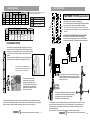
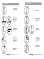
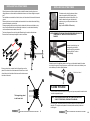
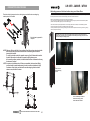
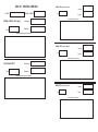
PRO LIFTING TOWERS
Using & Installation user manual
LW 465 R
LW 480 R
WT 600
EN
Rev. 12.5.6
LW 465R/480R/WT 600 LIFTING TOWERS
INSTALLATION AND USER MANUAL
LW 465 R
LW 480 R
WT 600
LW 465R/480R/WT 600 LIFTING TOWERS
INSTALLATION AND USER MANUAL
INTRODUCTION
1
FEATURES
2
SPECIFICATIONS
3
FASTENER SYSTEM (explanation)
3
SAFETY RULES
5
INSTALLING THE LIFTING TOWER
9
PLACING THE LOAD
10
WINCH OPERATION (Special care)
13
LIFTING PROCESS
14
DESCENT/FOLDING PROCESS
16
CONFORMITY DECLARATION
19
BGV C1, EXPLANATION & TEST
20
FEATURES
INTRODUCTION
2º
LW 465R and LW 480R are the new lifter towers of WORK® One serial of towers produced in steel
and entirely safe. They are able to lift loads all straight from the soil up to a height of 8 m (LW 480 R)
or 6,5 m (LW 465 R), without any effort for the user. These towers have a different number of
profiles with the goal of reaching the maximum elevation (5 sections for LW480 R and 4 for
LW465R). It special design reaches a total reliability due to its multiple security systems, locking
system or independent blocking pins for each section.
As usual in WORK® products, all the components have been oversized with the goal of achieving a
superior security:
- High resistance aluminium profiles.
- Powerful autoblocking bolts.
- Steel made pulleys.
- Autoblocking certified winches.
These towers have a light inclination (2º) over the vertical axis in
order to displace the gravity centre to the opposite side of the
load, getting a better balance with the coupled load.
For the transport, LW 465R and
LW 480R incorporate a folded wheel
system.
- 2 iron braces placed in the back side to reinforce.
- Bubble level indicator vial
- High resistance legs.
- Strong cable of security made of steel under the DIN
normative
With this system, is posible to make more easy
the transport process in a lorry or track, the wheel
allow to lean the tower over the lorry base and to
displace it So the winch does not suffer scratches
or hits.
WT 600
Taking adxperience and good sucess
obtained in effectiveness, security and
endurance with the system used in our
Series 400 Lifting towers, we have
develop WT 600 for the elevation of
Line Array systems.
The transverse pieces placed between the base
and mast provide an extra firmness
Additional wheels for an easy load up or get
down process from a lorry or track.
(Only LW 400 series)
Its innovate design in the profiles section,
allowsto this lifting tower, the elevation and
supportof heavy loads (up to 350 Kg) to a
maximum height of 6 m., Making them very
adecuate for big complexity shows.
The ground strenthening system has been
conscientiously studied, providing to the
tower of a sujection legs of high length
with inclinated stabilizers.
To carry on system designed for Line
Array support has been reinforced
taking in account the exerted force, so
the thickness of metallic walls and
sujections rings, is superior, incroporating
also an angle finishing that allows to
give out the load over the whole
support in equitable way.
Fork carrier profile in order
to support the elevated load.
IMPORTANT
For WT 600 model.
ALL DRAWINGS IN THIS USER MANUAL
ARE BASED ON LW 480R LIFTING
TOWER. THE MODELS LW 465R
& WT 600 INCORPORATE
THE SAME OPERATION METHOD.
INSTALLATION AND USER MANUAL LW 465R/480R/WT 600 LIFTING TOWERS
1
INSTALLATION AND USER MANUAL LW 465R/480R/WT 600 LIFTING TOWERS
2
SPECIFICATIONS
MAX
LOAD
(KG)
MIN
LOAD
(KG)
DISPLAYED TOWER
HEIGHT
(M)
SPECIFICATIONS
Standards and Regulations applied on winches
incorporated on each lifting tower.
FOLDED TOWER
BASE
(M)
HEIGHT
(M)
BASE
(M)
WEIGHT
(KG)
LW 465 R
370
30
6,5
2,30 x 2,00
2,20
0,70 x 0,60
200
LW 480 R
320
30
8,0
2,30 x 2,00
2,20
0,70 x 0,60
220
WT 600
350
30
COMPOS.
(GALVANIZED)
6,5
Ø
(mm)
2,00 x 1,85
2,20
0,80 x 0,60
MODEL
205
LW 465 R
DIN 15020 / VGB 1 / VGB 8
LW 480 R
DIN 15020 / VGB 1 / VGB 8
WT 600
DIN 15020 / VGB 1 / VGB 8
WEIGHT/Mt ROLL.
(N / mm2) (KN - KP)
(KG/M)
BOBBING
CAPACITY
(m.)
TO THE NEXT
PROFILE
FROM THE
WINCH
WINCH
CABLE
RESIST. LOAD
FASTENER SYSTEM (explanation)
STANDARDS AND REGULATIONS
REDUCT.
RANGE
LW 465 R
LW 480 R
6 x 19+1
7
1770
26.7 - 2710
WT 600
0,170
CROSSED
TO
RIGHT
30
The fastener system operates in following way:
We turn clockwise the winch that thighten the cable and thanks
to the pulley system, the more outer profile is elevated.
This situation is not 100% assured. The load could deploy an
intermediate section but the lifting process will restore the normal
unfolding.
ALL SECURITY BOLTS MUST BE IN BLOCK POSITION,
so the elevation of the profile cause that the spring pin
of the bolt retracts, which triggers when a hole of the profile
is located in paralell with it, blocking the tower in that position.
10.5 : 1
FASTENER SYSTEM
PROFILE 1
PROFILE 2
This system uses a profiles specially designed in order to bear
heavy loads.The wide of these profiles and the thickness of their
walls ensures a big firmness of the set. These profiles incorporate
a rail with a serie of fixation holes where the security bolt are
located.
These holes have the sufficient size in order the bolts could be
introduced quickly, providing the folding speed of the tower.
PROFILE
(section view)
BOLT LOCATED
IN A BLOCK
POSITION
LOAD
The profiles have been designed with a
cylindrical reinforcement along then which
arise de strength of the whole tower.
In this point, there is a strain in the cable in order
to keep unfolded the pulley system, but all load is
supported by the security bolts, releasing the winch
and give up using it.
The security bolts have been
oversized as much as piston
diameter as main fixation piece.
The block/unblock system through
a light pull and turning it allows to
make these operations easily and
above all with security.
We continue elevating the tower up to the security
bolt locates in the las hole of the elevated profile.
In that moment, the next profile is elevated
identically up to total tower folding.
The pulley system (upper and lower on each profile) entrusts to transmit the generated strain
in the winch and to elevate the profiles, for this reason, these pulleys disposes of an appropiate
design in order to handle the cable, enclosing the whole system in a compact set.
INSTALLATION AND USER MANUAL LW 465R/480R/WT 600 LIFTING TOWERS
3
For the descent, we must to unblock the lower security bolt and turn the winch on inverse
sense, the load bring down the profile up to the stand position, in that moment we must
to block the bolt for the transport use and we must unblock the new security bolt from
the descended profile.
We proceed in the same way, with all profiles up to the total tower unfolding.
INSTALLATION AND USER MANUAL LW 465R/480R/WT 600 LIFTING TOWERS
4
SAFETY RULES
SAFETY RULES
LOAD
Do not elevate the tower
without using the stabilize
legs.
Do not move the tower
after the load is elevated
Place the tower over a flat
and stable surface.
Do not install it in a place
where the use over the
stabilize leg would not
be enough to reach a
perfect balance.
FRONT SIDE
Do not lean elements (like
stairs, platforms, scaffoldings,
etc.) over the tower which can
make pressure over it and
to destabilize
The two largest legs
must be placed in the
frontal tower side and the
shortest ones at both
winch sides.
For outdoor installations
ensure the tower with
security tights to ground.
NEVER fix them to surfaces
with oscillations like structures,
etc.
REAR SIDE
Act individually over the
stabilize leg up to the
wheels lose contact with
the ground and enssuring a
perfect balance of the
tower. This balance will be
showed in the vial.
BANNER
Do not use the tower
in heavy wind conditions.
Take into account that if the
exposed height and surface
is maximum, the tower stability
is reduced.
LOAD
Do not move away the
stabilizer legs after the
load is elevated.
INSTALLATION AND USER MANUAL LW 465R/480R/WT 600 LIFTING TOWERS
Do not use the tower
like support for banners
or decorates support. With
heavy wind, these elements
could act as “sail” and to
knock over the tower.
5
INSTALLATION AND USER MANUAL LW 465R/480R/WT 600 LIFTING TOWERS
6
SAFETY RULES
SAFETY RULES
The load must be firmly placed
over the support the nearest
possible gravity center of the
tower, in order to facilitate its
balance.
Keep the hands and fingers
moved away to mobiles
elements of the towers
like profile unions.
Do not lubricate the brake
system of the winch, the
mechanism could lose
efficiency.
Do not catch the cable
during the elevation or
folding process.
In the moment you elevate the tower,
check that it does not take contact
with elements or objects which with
the tower could hit or come off.
?
?
?
?
Do not overload the tower beyond
the max. weight recommended in
the manufacturer specifications.
?
OI
L
Avoid the non-desired tower
manipulation by non-qualified
people.
Check periodically the good
winch conditions of the and
cable security. In order to
guarantee the security cable
integrity, consult the section
about the winch operation.
Be aware specially with the electrical
conductions, due to the towers are
not electrically isolated, it can
represent a serious electric shock
danger.
NOT TAKE INTO CONSIDERATION THESE RULES COULD CAUSE THE KNOCK
OVER OF THE TOWER OR ITS LOAD, PROVOCATING DAMAGES IN PEOPLE
AND PROPERTIES
Do not stay down to the tower
after the tower elevation nor
elevation or folding process.
This tower is not designed
to elevate persons. Do not
use it for a different purpose
that it has been designed
INSTALLATION AND USER MANUAL LW 465R/480R/WT 600 LIFTING TOWERS
7
INSTALLATION AND USER MANUAL LW 465R/480R/WT 600 LIFTING TOWERS
8
INSTALLING THE LIFTING TOWER
INSTALLING THE LIFTING TOWER
Place the tower over a flat and stable surface to install the tower, discarding its use over
rolling platforms or surfaces which would be able to bear as much its own weight as coupled
load.
The installation area must be free of debris, stone, etc. that reduce the firmness of the tower at
ground.
Moreover the tower must no be placed near elemenst which can obstruct the vertical folding
process like balconies, cornices, etc.
Be aware specially with the proximity of electric cables which the tower could take or crimp
them. Consider that the tower is not electrically isolated, so, it can be load with electricity
and to constituate a serious electric shock risk.
For better security during the transport, these
towers incorporate a profile fixation system
that impede the movement of the profiles. You
must to release it acting over the piece with
extension spring and the piece located in the
fixation hole.
(Only for LW 461R/LW 476R models)
The tower disposes of two sets of legs with different length in order to settle the tower
Remove them for the transport support in order to insert them.
NOTE: REMEMBER TO RELEASE THIS DEVICE BEFORE ELEVATING THE
TOWER AND FIX IT WHEN THE FOLDED PROCESS IS
FINISHED
In order to insert the legs, use
corresponding pin bolt and
insert the leg to correct position
triggering the bolt To ensure
the set stability.
Pin bolt for
leg insertion
Rotate the crank of the stabilizer placed on each legs up to the wheels located in the base
do not touch the ground. During this process, control the vial in order to act individually over
each stabilizer up to obtain a perfect balance.
When you place them, consider that the 2 longest legs must be
placed in the frontal side of the tower and the shorter ones in both
sides of the winch frontal side of the tower and the shorter ones in
both sides of the winch.
Vial for level control
PLACING THE LOAD
Once the tower is fixed and balanced over the ground, you can proceed to locate the load
over the incorporated support.
The longest legs placed
NOTE: THE HOLDER DESIGN ALLOWS THE LOAD ELEVATION FROM
30 CM OF THE GROUND, PROVIDING ITS HANDLING.
in the frontal side.
For this purpose, remove the external bolt located on each arm in order to make the
extraction. This support must be placed in horizontal position and the pin bolt must
be fixed again.
INSTALLATION AND USER MANUAL LW 465R/480R/WT 600 LIFTING TOWERS
9
INSTALLATION AND USER MANUAL LW 465R/480R/WT 600 LIFTING TOWERS
10
PLACING THE LOAD
PLACING THE LOAD
Before elevating the tower, you must unblock the security bolt located in the wheel
transport system, so the wheel pass to stand position and the elevation process can start.
Support in stand position for transport.
Extract the pin bolts and place it in
horizontal position in order to locate
the load.
(Only for LW 465R/LW 480R models)
Unblock this
bolt.
LOAD
> 30 Kg
WT 600
Support in stand position for transport. Extract the pin bolts and place it in
horizontal position in order to locate the load.
NOTE: IN ORDER TO ELEVATE TRUSS
SYSTEMS, THERE IS AN OPTIONAL
DEVICE IN “U” SHAPE WHICH IS
FIXED THROUGH THE HOLES OF
THE SUPPORT AND PROVIDED
AN APPROPIATE FIXATION FOR
THIS TYPE OF LOAD.
Place the load over the support, taking into account the security recomendations indicated in
the HANDLING PRECAUTIONS section, like this:
- To assure stability and balance of the lifting tower.
- To place the load the nearest possible to the gravity center of the tower in order to avoid the
“ lever effect”.
- Do not overpass the weight recommended in the manufacturer specifications.
- To assure and fix the load in order to avoid load movements.
AD
LO
(U
pto
0
35
Kg
).
NOTE: In order to make easy the load descent process and tower folded, the
minimum load coupled on the tower must not be smallest than 30 Kg.
INSTALLATION AND USER MANUAL LW 465R/480R/WT 600 LIFTING TOWERS
11
INSTALLATION AND USER MANUAL LW 465R/480R/WT 600 LIFTING TOWERS
12
LIFTING PROCESS
PLACING THE LOAD
HINT: IT IS POSSIBLE TO OBTAIN AN EXTRA HEIGHT, FLIPING THE SUPPORT. FOR THIS
OPERATION, YOU MUST RETIRE THE CENTRAL SCREW AND TO CHANGE THE
POSITION ON THE SUPPORT PIECE.
Central Screw
(Retire it in order
to flip the support
piece)
NOTE: BEFORE ELEVATING THE TOWER, CHECK THAT ALL BOLTS ARE
IN BLOCK POSITION.
Final position with the
support flipped.
Blocked bolt
(CORRECT)
NOTE: MIND IF THE LESS ADDITIONAL HEIGHT OBTAINED WITH THIS WAY,
MAKE UP FOR THE INCREASE OF THE LOAD FALL RISK.
THIS OPERATION MUST BE MAKE BY QUALIFIED PERSONNEL.
WINCH OPERATION ( SPECIAL CARE)
During the tower elevation process, pay attention to the cable rolling.
This cable must the coiled in parallel turns around the winch cylinder NEVER MUST
BE PRODUCED CABLE CROSSES IN DIFFERENT DIRECTIONS.
Turn the winch smoothness in
clockwise direction, during
this process, the load will
start to elevate with the
support. Be carefull in all
moment with oscillations due
to a defficient load.Continue
with this process up to the
support reach the prefixed heigh.
Unblocked bolt
(INCORRECT)
LOAD
LOAD
Load located in the most
elevated point
In this way, that cable can be dangered or got worn, causing, at the end, the break of the cable.
(Before to folding it)
If any spiral is rolled in this way, turn the winch in opposite sense up to release of wrong turn.
Then, proceed to coil again in an appropriated way
CORRECT MODE
Coil direction during
the elevation process
The cable must be
coiled in parallel coil
From this moment, the zip system in the profiles start to operate.
Each profile is designed in order to carry out a double objective:
To house the security system from the previous profile and to arrange
the appropiate insertions in order the bolt of the next profile
acommodate during the elevation process.
WRONG MODE
Turned in cross way.
Try to avoid it in order
to keep the cable integrity.
INSTALLATION AND USER MANUAL LW 465R/480R/WT 600 LIFTING TOWERS
INSTALLATION AND USER MANUAL LW 465R/480R/WT 600 LIFTING TOWERS
13
14
LIFTING PROCESS
DESCENT/FOLDING PROCESS
For the descent, we must to unblock the lower security bolt and turn the winch on inverse
sense, the load bring down the profile up to the stand position. In that moment, we must
to block the bolt for the transport use and we must unblock the new security bolt from
the descended profile.
We proceed at the same way with all profiles up to the total tower unfolding.
LOAD
1. Now you can turn the winch in clockwise
direction, the first profile starts to elevate
and the security bolt of the next profile
moves slightly to the outside when a solid
part of the profile passes in front of it.
2. You can continue elevating the
profile up to fully folded, that
coincide with the block of the
bolt over the last fixation hole.
Finally, we must descend the support system up to the position
more lower and removing the load.
Now, we must dismantle the fork carrier set, releasing the pin
and inserting the two forks in its transport position (vertically).
Insert the two fork
vertically and block
with the two pins.
This situation is not 100% assured. The load could deploy an intermediate
section but the lifting process will restore the normal unfolding.
3. In this detail, you can appreciate
the holes that allow to block the
security bolts, its shape allows
a better balanced of the coupled
load.
Ensure the profiles placing the fixation bar and ensuring with the pin.
Rotate the crank of the stabilizer placed on each legs up to the wheels located
in the base touch the ground.
This process must be make step by step, that is, several rotations one
each crank avoiding the unbalacing of the lifting tower until to
complete the process
4. Once fully folded the first profile, the friction
between profiles ocasssionated by the load,
do that the next profiles elevate by the same
way. When the trigger is shoted over the
last fixation hole in the profile, the last
profile is elevated.
Pin bolt for
leg insertion
This is the aspect of the LW 461 R with its 4
profiles folded at its max. Height. In this way
it is able to elevate loads up to 6.5 meters.
INSTALLATION AND USER MANUAL LW 465R/480R/WT 600 LIFTING TOWERS
15
In order to extract the legs, use
corresponding pin bolt and
extract the leg triggering the
bolt.
INSTALLATION AND USER MANUAL LW 465R/480R/WT 600 LIFTING TOWERS
16
LW 465R - LW480R - WT600
DESCENT/FOLDING PROCESS
Unblocking process of a blocked section using one of these lifters
Place them in the leg transport enclosure, taking into account that the two more longer leg
must be placed in the outside.
In the case of the lifter would be loaded with a weight much more superior than the one recommended, it could happen than
the safety cable breaks. In this case the internal safety system will act and block the section.
Moreover, during the folding process, one of the sections can be blocked.
Only on this case, just elevating the section some centimeters and folding it again, the problem is solved. But if the problem
persists or the first possibility happen, proceed on the following way:
These 3 lifter models incorporate, apart from the common safety system built-in all models, an internal blocking pendular
system, which will block the section and his adjacent with a friction system.
The way to release the system is acceding to it through the hole marked in the photo closed and using an Allen key, pushing
down the plunger until releasing it.
Now the tower is prepared for
transport.
IMPORTANT: This process must be realized without load and taking all neccessaries protection
measures due to the cable system is not thightened and realiasing the security system, the section
will reach suddenly the standby position.
NOTE: When you lift down the lifter, if any sections will not fully go down, stop to rotate the
winch because the system will be loosened and it would bring about a sudden
descent of this section.
To avoid it, rotate the crank in the opposite sense as if you lift down and insure that
the bolt of this section is unblocked, so repeat the lifting down process.
In the case the problem persists, look after that the lifter has a minimum load to easy
the descent of sections.
NOTE: In systems or intallations where 2 lifters are assembled, the descent (and lifting)
process should be make simultaneously in order to avoid an unbalance of heigh
in whatever of both sides, and that could cause the swinging of the load and in
extreme cases, the fall of the tower.
Point access to
internal blocking
system
To use an Allen key or similar to
release the security system
and to unblock the section.
INSTALLATION AND USER MANUAL LW 465R/480R/WT 600 LIFTING TOWERS
17
INSTALLATION AND USER MANUAL
LIFTING TOWERS
BGV C1 REGULATION, Explanation
CONFORMITY DECLARATION
Applicant
:
EQUIPSON, S.A
Address
:
Avda. El Saler, 14 Pol. Industrial L´Alteró
46460 SILLA - Valencia (Spain)
Representative
:
EQUIPSON, S.A
BGV C1 is a regulation for Staging and Production Facilities for the
Entertainment Industry. Lifting and rigging equipment is just part of this
standard and cover structures and other technical matters.
Adopting
BGV C1 is entirely voluntary (except in Germany) but its adoption is
generally required by insurance companies and therefore it has effectively
become an industry standard.
The application of this standard over lifting towers is vital due
to in theatres, stages, etc. are used to move loads over performers
and, in some cases, above spectators, representing a potential falling risk.
Address
:
Avda. El Saler, 14 Pol. Industrial L´Alteró
46460 SILLA - Valencia (Spain)
BGV C1 REGULATION, Application fields
Description
:
The described Truss-Lifts meets all the requirements specified in the Directive 2006/42/EC
of the European Parliament and the Council of 17 May 2006 on machinery, and
amending Directive 95/16/EC.
Lifts for Truss Systems
WORK®
WORK®
WORK®
LW 465 R
LW 480 R
WT 600
Juan José Vila
(Product Manager)
October 22, 2009
The test report was carried out from the submitted type-samples of a product in
conformity with the specification of the respective standards. The certificate holder has
the right to fix the CE-mark on the product complying with the inspection samples.
This standard is orientated in two ways:
By one side, the lifting towers adopt designs and materials in order to
achieve a high security degree in magnitudes like load supported,
balance, friction resistance, etc.
So a WORK® lifting tower BGV C1 certified ensures the customer
that has passed strict test during its design, materials choice or
load and effort verifications.
By other side, in order to achieve an optimum operation with these
units, is recommended as much a responsible use of the unit,
complying basic rules like maximum load accepted or tower balance
as maintenance periodic, which must be carried by expert technicians,
checking the good state of the steel cable and winch, operation of
the safety bolts and folding/unfolding of the entire profile system.
BGV C1, TESTS & CHECKS
MODEL
SERIAL NUMBER
ANNUAL TEST (passing the fourth year)
Date
Checked by
Signature
Tested elements and conclusions
INITIAL CHECK (First year)
Date
Checked by
Signature
Tested elements and conclusions
ANNUAL TEST (passing the fourth year)
Date
Checked by
Signature
Tested elements and conclusions
FOUR YEARS TEST
Date
Checked by
Signature
Tested elements and conclusions
ANNUAL TEST (passing the fourth year)
Date
Checked by
Signature
Tested elements and conclusions
www.worklifters.com
EQUIPSON, S.A. Avda. del Saler, 14 - Pol. Ind. L´Alteró (Silla) - 46460 Valencia- Spain- Tel. +34 96 121 63 01 - Fax +34 96 120 02 42 [email protected]/www.equipson.es