1
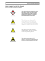
Nitrogen Laser OPERATION MANUAL WARNING: Operation or adjustment of this product inconsistent with the instructions herein can result in hazardous radiation exposure. Nitrogen Laser OPERATION MANUAL Copyright © 2008 PTI. All Rights Reserved. PTI is a registered trademark of Photon Technology International, Inc., 300 Birmingham Road, P.O. Box 272, Birmingham, NJ 08011 Phone: (609) 894-4420 Fax: (609) 894-1579. Website: www.pti-nj.com Specifications and contents are subject to change without notice. 2 Photon Technology International Trademark and Proprietary Information All materials on this document, including but not limited to: text, images, and illustrations (collectively, the "Materials") are owned or controlled by PTI. Trademarks apply. The materials contained in this document are subject to change without notice. PTI makes no warranty of any kind with regard to this material and shall not be liable for errors contained herein or for incidental consequential damages in connection with the furnishings, performance, or use of this material. You may not copy, reproduce, republish, upload, post, transmit or distribute the materials in any way whatsoever without prior written approval from authorized personnel of Photon Technology International. PTI® and the PTI logo are registered trademarks of Photon Technology International, Inc. The following product names are all trademarks of PTI: DeltaScan™ DeltaRAM™ FeliX™ ImageMaster™ ImageMaster Pro™ QuadraCentric™ QuadraScopic™ QuantaMaster™ RatioMaster™ TimeMaster™ TimeMaster Pro™ Oscar™ PowerFilter™ FilterScan™ Felix32™ Brytebox™ No trademark and no material from any PTI documentation may be used in any form without prior written permission from Photon Technology International, Inc. All pages and their contents are copyright © 2008 Photon Technology International, Inc. All rights reserved. Specifications are subject to change without notice. All other trademarks are the property of their owners. Nitrogen Laser 3 PTI Standard Instrument Warranty Warranty Period and Extent Photon Technology International (PTI) warrants that its instruments will be delivered in a functional state and free from defect, and will meet stated specifications for a period of one (1) year. The warranty period will start on the date of shipment by PTI. In case of systems that include installation by PTI, the warranty will start from the date of installation or thirty (30) days after the shipping date, whichever is earlier. This warranty is in lieu of all other warranties, expressed or implied, including, without limitation, the implied warranties of merchantability and fitness for a particular purpose, nor will PTI provide training on its use free of charge. PTI shall not be responsible for any liability, loss or damages, caused or alleged to be caused, by the system, as a result of use or operation including, without limitation, consequential damages and loss of profit. Specific Exclusions and Limitations 1. It is recognized that the performance of consumable items will diminish as a function of use, and that it may be necessary to replace such items to restore the stated specifications. Consumable items (arc lamps, filters, cuvettes, lenses, etc.) are not covered by the warranty. 2. The original manufacturer's warranty will be maintained for major system components not manufactured by PTI (e.g. computers, printers, microscopes, cameras and components thereof). 3. Fiber optic bundles are not covered by the warranty. 4. The use of arc lamps not supplied by PTI (or approved in writing by PTI) will void PTI's warranty on all illuminator subsystem components. 5. If there is any evidence of physical contact with coated optics (e.g. fingerprints), the warranty on that item will be voided. 6. If the optical components are realigned by the customer without specific permission from PTI, the warranty will be voided. Please note that the customer is responsible for changing lamps and aligning the lamp after installation. Aligning the lamp will not void the warranty unless other exclusions are applicable (nos. 4 and 5). 7. Instrument systems that are not authorized to be installed by anyone other than PTI service personnel will not be warranted. 8. In case of systems that include installation as part of the original purchase, unpacking the instrument by anyone other than PTI personnel will void the warranty. 9. Moving systems to another site within a facility or to another location, without specific permission from PTI, will void the warranty. 10. Damage or loss caused by shipping is not covered by the warranty. 11. Damage caused by improper operation of the instrument will void the warranty. 12. Damage caused by equipment not purchased from PTI that is attached to the instrument is not covered by the warranty. 13. Warranty is valid only in the state, province or country of the original purchase. 14. Warranty is valid only on systems having a computer supplied by PTI. 15. Software upgrades performed on the PTI computer workstation (e.g., adding word processors, image editors, etc.) not authorized by PTI will void the warranty. 16. Hardware upgrades performed on the PTI computer workstation (e.g., adding network boards, sound cards, etc.) not authorized by PTI will void the warranty. Warranty Returns A Return Material Authorization (RMA) Number must be obtained from the PTI Service Department before any items can be shipped to the factory. Returned goods will not be accepted without an RMA Number. Customer will bear all shipping charges for warranty repairs. All goods returned to the factory for warranty repair should be properly packed to avoid damage and clearly marked with the RMA Number. Warranty Repairs Warranty repairs will be done either at the customer's site or at the PTI plant, at our option. All service rendered by PTI will be performed in a professional manner by qualified personnel. Software PTI makes no warranties regarding either the satisfactory performance of the software or the fitness of the software for any specific purpose. PTI shall not be responsible for any liability, loss or damages caused or alleged to be caused by our software as a result of its use, including, without limitation, consequential damages and loss of profit, nor will PTI provide training on its use free of charge. 4 Photon Technology International Safety Symbols Used In This Manual (NOTE: Not all may be present in this manual) (DANGER) This symbol indicates the potential for serious bodily harm. Extreme care should be taken when performing the task and all warnings should be strictly adhered to. All possible steps should be taken to ensure safety. (WARNING) This symbol represents the potential for electrical shock and/or other bodily harm. Care should be taken when performing the task. There is also the potential for damage to equipment if warnings are not taken seriously. (CAUTION) (RADIATION) This symbol represents the potential for equipment damage. The user is expected to use care when performing the task. This symbol represents the risk of UV radiation. User must take all appropriate steps to protect eyes and exposed areas of the skin. Nitrogen Laser 5 Contents Trademark and Proprietary Information ............................................................2 PTI Standard Instrument Warranty ....................................................................3 Safety Symbols Used In This Manual ...................................................................4 Contents ...................................................................................................................5 List of Figures .........................................................................................................5 1 General .................................................................................................................6 Quality Control Report ...........................................................................................................6 Dimensions ................................................................................................................................7 Controls and Indicators ...........................................................................................................8 Warning Labels ......................................................................................................................10 Specifications ..........................................................................................................................11 2 Operation ............................................................................................................12 Initial Setup ............................................................................................................................12 Operation ................................................................................................................................13 3 Service .................................................................................................................14 Maintenance Schedule ...........................................................................................................14 Cleaning and Adjusting SG1 .................................................................................................16 Cleaning and Adjusting SG2 .................................................................................................20 Cleaning the Laser Channel and Mirror .............................................................................24 Troubleshooting .....................................................................................................................27 Service Calls to PTI ................................................................................................................28 List of Figures Figure 1 - Dimensions ...................................................................................................................7 Figure 2 - Control Panel ...............................................................................................................8 Figure 3 - Adjusting the gas flow ...............................................................................................13 Figure 4 - Laser head assembly ................................................................................................. 15 Figure 5 - Spark Gap 1 ...............................................................................................................16 Figure 6 - Spark gap 2................................................................................................................. 20 Figure 7 - Spark gap 2 insulator showing graphite ring.......................................................... 21 Figure 8 - Laser channel assembly ............................................................................................ 24 6 Photon Technology International 1 General Quality Control Report Nitrogen Laser Serial Number ___________ Key Number ______________ Before this laser was shipped from the plant, it underwent strict and thorough quality, safety and performance testing. The following is a report of the test results. Safety Checklist Indicators: □ Power □ Laser Interlocks: □ Cover □ Remote □ Key Switch □ Shutter □ Fuse □ Labels Performance Checklist Line voltage1 Output Energy __________ 2 __________ __________ __________ At Rep Rate __________ __________ __________ Voltage __________ __________ __________ __________ __________ __________ Gas Pressure, G1 __________ __________ __________ Gas Pressure, G2 __________ __________ __________ Gas Flow 3 1 The nitrogen laser must be operated at this line voltage. 2 Measured on a calibrated Gen Tec ED-200 Joulemeter. 3 Refer to page 13 for proper reading of the gas flow. Tested by ___________________________________________ Date ________________________ Ref. No. ______________ □ H. V. Delay Nitrogen Laser 7 Dimensions Inches [mm] PULL TO CLOSE BEAM APERTURE 29.25 [743 ] 20. 25 [514] DANGER INV ISIBLE LASER RADIATION. AVOID DIRECT EXPOSURE T O BEAM 9.25 [235] MAX AVERAGE POWER: MAX ENERGY / PULSE: PULSE DURATION: WAVELENGTH: CLASS I I I b 56 mW 2.8 mJ 800 ps 337.1 nm LASER PRODUCT AVOID EXPOSURE I N V I S I B L E E M I T T E D 4.62 [117 ] 13 [330 ] Figure 1 - Dimensions L A S E R F R O M R A D I A T I O N T H I S I S A P E R T U R E 20 8 15 9 Figure 2 - Control Panel TRIGGER IN 13 11 12 17 SYNC OUT EXT MODE INT MODE REP RATE 10 0 12 kV 18 5 GAS FLOW HV ADJUST 6 120 V FUSE ON POWER 2.5 AMP SB LASER ON DANGER INVISIBLE LASER RADIATION WHEN OPEN AND INTERLOCK DEFEATED OR FAILED AVOID DIRECT EXPOSURE TO BEAM 7 10 20 0 6 0 1 30 psi kPa 200 60 50 + LIFT AND TURN TO ADJUST _ 0 600 80 psi kPa 1000 800 G2 80 PSI 200 400 18 NITROGEN 0 40 14 GAS PURGE 2 G1 ADJUST 400 40 19 300 G1 45 PSI 100 THIS PRODUCT CONFORMS TO PROVISIONS OF PERFORMANCE STANDARDS 21CFR 1040 – 10 & 11 FOR LASER PRODUCTS MADE IN CANADA 24 21 3 REMOTE 160 120 4 16 8 Photon Technology International Controls and Indicators Nitrogen Laser 1 A.C. line cord connector. 2 Fuse holder. 3 Nitrogen input. The input pressure is displayed on the gauge marked G2 above the input. 4 G2 gauge. Displays the input pressure and the pressure in Spark Gap 2. 5 Main power key switch. The key cannot be removed when the laser is operating. 6 POWER indicator. Illuminated when laser system power is on. 7 LASER ON indicator. Illuminated 10 seconds after system power is turned on. 8 Trigger mode selector. Selects either internal trigger operation or external trigger source. 9 Rep rate control. Controls the rep rate when the trigger mode is set to internal. 9 10 Trigger In button. When the trigger mode is set to external, a single laser pulse is emitted when this button is pressed. When the trigger mode is set to internal, laser pulses are momentarily interrupted when this button is pressed. 11 Trigger In connector. BNC connector provides input for external trigger source. Trigger pulse must be > 3 volts and > 100 nanoseconds. 12 H.V. adjust control. Controls the voltage delivered to the laser head. 13 HV meter. Displays the voltage applied to the laser head. 14 Gas purge button. While this button is depressed, the system is purged with fresh nitrogen. 15 Sync Out connector. BNC connector provides a 1.5 μs wide, 24 V pulse, 1 μs before the laser fires. 16 Remote shorting connector. This connector must be installed for the system to operate. 17 Gas flow control. Provides fine adjustment of the gas flow to the laser channel. 18 G1 adjust control. Sets the gas pressure within the trigger spark gap. 19 G1 gauge. Displays the nitrogen pressure in the trigger spark gap. 20 Shutter. Opens and closes the laser output aperture. 21 Safety Interlocks. Popup switches situated behind the panel that cut power when the lid is open. 10 Photon Technology International Warning Labels SERIAL# 1456 MODEL# GL-3300 MANUFACTURED: J u n e 2 0 0 6 Photon Technology International (Canada) Inc. DANGER MADE IN CANADA VOLTS: 120 VAC FREQ: 50-60 HZ INVISIBLE LASER RADIATION. AVOID DIRECT EXPOSURE TO BEAM AMPS: 2.5A WATTS: 100W MAX AVERAGE POWER: MAX ENERGY/ PULSE: PULSE DURATION: WAVELENGTH: 347 Consortium Court London Ontario Canada N6E 2S8 RIVETED TO BACK PANEL CLASS IIIb 56 mW 2.8 mJ 800 ps 337.1 nm LASER PRODUCT LOCATED ON FRONT PANEL ABOVE APERTURE DANGER INVISIBLE LASER RADIATION WHEN OPEN AND INTERLOCK DEFEATED OR FAILED AVOID DIRECT EXPOSURE TO BEAM AVOID EXPOSURE INVI SIBLE LASER RADIAT I ON IS EM I T T ED FRO M T HIS APERT URE LOCATED ON FRONT PANEL BELOW APERTURE SILKSCREENED ON BACK PANEL NEAR INTERLOCK DANGER DANGER INVISIBLE LASER RADIATION WHEN OPEN HIGH VOLTAGE AVOID DIRECT EXPOSURE TO BEAM LOCATED ON TOP OF LASER HEAT SHIELD AND ALSO ON INSIDE BOTTOM OF LASER HEAT SHIELD LOCATED ON PLASTIC SHIELD OVER HIGH VOLTAGE AREA OF CIRCUIT BOARD THIS PRODUCT CONFORMS TO PROVISIONS OF PERFORMANCE STANDARDS 21CFR 1040-10 & 11 FOR LASER PRODUCTS M AD E I N C AN ADA SILKSCREENED ON BACK PANEL Nitrogen Laser 11 Specifications DANGER INVISIBLE LASER RADIATION. AVOID DIRECT EXPOSURE TO BEAM MAX AVERAGE POWER: MAX ENERGY/ PULSE: PULSE DURATION: WAVELENGTH: CLASS IIIb 56 mW 2.8 mJ 800 ps 337.1 nm LASER PRODUCT Conformity Performance standards 21CFR 1040-11 & 11 for laser products Peak power at 5 Hz 1.45 MW Maximum average power 56 mW Energy per pulse at 5 Hz 1.45 mJ Maximum energy per pulse 2.8 mJ Pulse width 1 ns Spectral output 337.1 nm Spectral bandwidth 0.1 nm Repetition rate Single shot to 20 Hz Energy stability, peak to peak ±2.5 % Beam dimensions at exit 3 x 6 mm Beam divergence 3 x 7 mrad Lasant, recommended purity N2 gas, ≥ 99.995 % Dimensions (in) 29.251 x 20.25 x 9.25 Dimensions (mm) 7431 x 514 x 235 Weight (lbs) 85 Weight (kg) 39 Line (mains) voltage2,3 95 – 125 VAC, 50/60 Hz Power rating 100 W Fuse 2.5 A, SB Notes: 1) End plate to end plate distance. Add 3.0 inches (77 mm) for knobs, cables, nitrogen hose. 2) The nitrogen laser must be modified at the factory depending on the specified line (mains) voltage. 3) A step down transformer can be supplied for countries that operate at 210 – 240 VAC. 12 Photon Technology International 2 Operation Initial Setup Laser quality nitrogen (≥ 99.995 % purity) is required for the operation of the nitrogen laser. A suitable two-stage gas regulator with a fabric-reinforced neoprene diaphragm that gives 100-150 PSI maximum output pressure must be provided and it is recommended that the output from the pressure regulator be through an on/off valve for flow regulation. The nitrogen laser is provided with 8 feet of 1/4 inch OD tubing with a Parker 68P-4-4 connector to connect to the on/off valve or regulator. The regulator or on/off valve must have a 9/16"-18RH(F) outlet connector to fit this. WARNING! Always use laser safety goggles designed for UV nitrogen lasers or severe and permanent eye injury may result. 1. Connect the N2 supply and set the pressures as indicated on the rear panel gauges. 2. Close the shutter. 3. Select the external trigger mode. 4. Turn the key switch on (the POWER indicator will light). 5. Press and hold the gas purge button for 3 or 4 seconds to flush the system with fresh N2. 6. After a 10 second delay, the LASER ON indicator will light. 7. Refer to the Quality Control Report and the following section for the proper H.V., gas flow and rep rate control settings to obtain the expected output. 8. Switch to internal trigger mode or apply an external trigger signal and lasing will commence. 9. Open the shutter. Output may be monitored on an energy meter or observed on a fluorescent card. Nitrogen Laser 13 Operation Reference settings for normal operation are listed in the Quality Control Report at the front of this manual. The appropriate settings may need to be adjusted over time due to normal component wear, readjustment, etc. The spark gaps will operate in a range of ±20 % of rated pressure, so it is possible to compensate for some wear of the electrodes by lowering the pressure slightly. The gas flow through the laser channel is a critical operating parameter, and must be carefully adjusted to obtain full laser energy output. Also, different rep rates will require different flow rates. For this reason, a micrometer is used for fine adjustment of the gas flow. The rotating knob has 25 units per rotation, and one full rotation is equal to one division on the barrel. Four rotations of the knob will show a 1 on the barrel indicating 100 units of gas flow. The gas flow is stopped when the knob and barrel both read 0. (refer to the example below). 0 1 5 0 20 GAS FLOW AT 175 0 1 20 15 10 GAS FLOW AT 16 Figure 3 - Adjusting the gas flow Gas flow is best optimized by using an energy meter. However, the sound of the discharge is also a good indicator; too little or too much gas flow will produce a much sharper sound, and the output energy will be lower or less stable. Purging the system with fresh N2 occasionally will help prevent misfires by flushing the spark gaps and removing discharge by-products. The rep rate of the nitrogen laser is from single-shot (in external trigger mode) to 20 Hz. Note that the internal mode rep rate control is not linear. In the control’s full counterclockwise position, the rate is approximately 0.6 Hz. In the full clockwise position, the rate is 20 Hz. When the indicator is in the vertical position, the rate is approximately 6 Hz. 14 Photon Technology International 3 Service Maintenance Schedule For a demonstration of regular nitrogen laser maintenance, see a technical movie clip on PTI’s website http://www.pti-nj.com/Technical-Movies.html, scroll to the bottom of the webpage and select GL 3300 Laser Maintenance Video. The GL-3300 is an older version of PTI's nitrogen laser, but there are no changes with respect to maintenance. There are two versions for viewing by either Windows Media Player or Apple's QuickTime. Optimum performance requires regular maintenance. The maintenance requirements of the nitrogen laser are minimal and relatively simple, and only involve the cleaning of components subject to gas impurity deposition. These components include the two spark gaps, the laser channel, and the laser mirror. Gas impurity deposition degrades performance; cleaning these components will bring your laser back to original operating specifications. The frequency of maintenance is dependent on the purity of the nitrogen gas and how many shots the laser has been fired. Lower rep rates require less frequent cleaning of the components. The following schedule is a general guide to determine when the laser components should be cleaned. (The recommendations are based on the assumption that lab grade nitrogen is used.) However, the performance of your laser should be used as the primary determinant for when cleaning is necessary. Cleaning Interval Component Spark gaps Laser Channel & Mirror Shots @ 5 Hz, 20 hr/week 2 – 10 million 6 – 30 million 5 – 28 weeks 15 – 84 weeks WARNING: Cleaning the spark gaps, laser channel and laser mirror requires opening the laser housing. This will expose dangerous high voltage and UV laser light sources. Under no circumstances should the laser system be operated while the lid is open. Disconnect the line power cord and gas supply before opening the lid. Nitrogen Laser 15 The figure below shows the location of the components requiring regular maintenance. GAP ADJUSTING KNOB SG-2 H.V. CONNECTOR SG-1 MIRROR HOUSING LASER ELECTRODE ASSEMBLY HEX NUTS (6) LOCKING SCREWS FOR LASER ELECTRODE ASSEMBLY Figure 4 - Laser head assembly Spark Gaps The PTI nitrogen laser uses two spark gaps to trigger the lasing process. The first spark gap (SG1) initiates the voltage multiplication process which develops across the two laser electrodes. One of these electrodes is in series with the second and larger spark gap (SG2), which acts as a breakdown gap. It quickly releases the potential from one laser electrode, thus creating the breakdown across the laser channel that results in the excitation of the nitrogen gas. Both spark gaps use nitrogen gas as their active medium. 16 Photon Technology International Cleaning and Adjusting SG1 Refer to the figure below when performing maintenance on SG1. Figure 5 - Spark Gap 1 1. Turn the key to shut off the laser power. 2. Turn off the N2 gas supply. 3. Remove the ten Phillips screws which hold the laser housing lid shut. It is hinged at the back. After removing the screws, lift the lid up and back. 4. Remove the four slot head screws and washers on top of the RFI shield in place, then lift the shield straight up. 5. The laser now has possible high voltage exposed. Short the laser head assembly to ground by touching the shaft of a long plastic handled screwdriver to the bottom of the laser head assembly and to the bottom panel of the laser housing. 6. Now remove the AC line (mains) cord from the wall plug and also from the back panel. 7. If you are going to clean and/or adjust both SG1 and SG2, then disassemble SG2 at this time before disassembling SG1 (go to Cleaning and Adjusting SG2, step 7). This is because you will need SG1 closed in order to apply nitrogen gas pressure to push the SG2 insulator out of the main housing. 8. Disassemble SG1. First, remove the white cap connected to the red wire from the spark gap trigger terminal. Then use a slot screwdriver to unscrew in a cross pattern, a few threads at a time, the four long slot screws holding the trigger housing and main housing to the bracket. This is so the trigger pin does not get pushed against the spark gap main housing. Remove the trigger housing and screws from the bracket. Nitrogen Laser 17 9. Grasp both hose connectors and wiggle the main housing away from the bracket. This is a snug fit because of the O-ring on the outside of the electrode holder. At this time, do not loosen the lock nut on the back of the mounting bracket or turn the electrode holder. 10. Remove the O-ring from the trigger housing face. 11. First wipe the interior of the electrode holder and the inside face of the trigger housing with a clean dry tissue (e.g., Kimwipe) and then dampen a clean tissue with methanol and wipe the interior of these pieces again. In the same way wipe the inside and outside of the main housing. 12. Use a vernier caliper to measure the distance the trigger pin electrode sticks out of the the plastic face of the trigger housing. This distance should be 0.175 inches (4.45 mm). If the trigger pin has been worn away and it needs to be adjusted, use a pair of pliers to unscrew the trigger terminal from the trigger housing. Use a 0.050 inch Allen wrench (hex key) to loosen the set screw in the side of the terminal. Pull out the trigger pin the approximate distance needed (this may vary depending on how much the O-ring at the base of the trigger pin is crushed when the terminal is screwed tight back into the trigger housing). The O-ring will come out with the trigger pin allowing you to estimate the distance added. Tighten the set screw against the trigger pin, then screw the terminal back into the trigger housing and tighten it with the pliers. Measure the distance and repeat this step as necessary. 13. After touching the trigger pin, it should be wiped again with a tissue dampened with methanol. 14. Check the adjustable electrode tip and adjust as necessary. a. During normal operation, the adjustable electrode will wear down over time. This increases the electrode gap, which can adversely affect laser performance. To compensate for this normal wear, the adjustable electrode must be moved. b. With SG1 disassembled, measure the distance from the electrode tip to the bracket (depending on your measuring device, you may need to remove the shutter cover plate). If it is less than 20 mm, the tip has worn and must be adjusted in order to maintain the factory setting of 2 mm. Loosen the lock nut and rotate the adjustable electrode holder, which is threaded into the bracket, until the tip-to-bracket distance is 20 mm (see figure 5). c. The adjustable electrode will eventually wear to the point that it must be replaced. Contact PTI to obtain a replacement. 15. Remove the white grid cap with the black wire on the high voltage terminal at the back of SG1. Check the tightness off the brass knob extending out of the white Teflon electrode holder. It may become loose because the Teflon changes size slightly over time. Turn this knob clockwise by hand to tighten it. Place the white grid cap back on the brass knob. 16. If you are cleaning and/or adjusting both SG1 and SG2, then reassemble SG2 at this time before reassembling SG1 (go to Cleaning and Adjusting SG2, step 19). 18 Photon Technology International This is because if SG1 is closed, it is harder to push the SG2 insulator into the main housing. 17. While holding the electrode holder securely with a pliers, place the main housing over the electrode holder open end and wiggle it to get it past the O-ring (do not twist the main housing over the O-ring as this may change the electrode gap inside the housing). Push the main housing so it is right up against the mounting bracket. Adjust the main housing rotation so that the lower left hose connector is above of and does not block the screw hole in the mounting bracket (the top hose connector will then be slightly counterclockwise (to the left) of vertical). 18. Place the O-ring back into its groove in the trigger housing. Insert the four long slot screws through the holes in the trigger housing. Orient the trigger housing so that the set screw is pointed away from the laser head. Carefully place the trigger housing against the main housing so that the trigger pin does not scratch the main housing and the trigger housing rotates freely on the O-ring. In a cross pattern start threading each of the screws a few turns into the mounting bracket. Check that the trigger housing can still move slightly with the O-ring against the main housing and that the four screws look square against the mounting bracket. Then tighten each screw a few turns at a time in a cross pattern to evenly crush the O-ring and to not tilt the trigger pin so that it contacts the side of the hole in the center of the main housing. 19. Put the white cap with the red wire back on the trigger terminal. 20. Put back the RFI shield over top the laser head assembly so that it fits inside the bottom shield and shut the laser housing lid. 21. Open the valve on the nitrogen gas tank. Make sure the SG2 gas pressure gauge reads 80 psi. Adjust the G1 Adjust knob so the SG1 gas pressure gauge reads 47 psi. 22. The initial tests will run the nitrogen laser at about 3 Hz. Turn the the gas flow gauge clockwise to the closed position and open it (counterclockwise) to read 25 units (one revolution from the closed position). 23. Connect the AC power (mains) cord to the nitrogen laser. 24. Turn the High Voltage Adjust knob counterclockwise to the stop position. 25. Move the mode switch to Internal Mode. 26. Turn the Rep Rate knob to approximately 45° counterclockwise (left) of vertical (about 10:30 on a 12 hour clock). This will set the rep rate at 2 – 3 Hz. 27. Turn the key switch ON (horizontal position). 28. Since the spark gaps were open to the air, they need to be purged about 10 to 15 seconds. 29. Check and adjust the gas pressures for both spark gaps again as they can change slightly when purged. Nitrogen Laser 19 30. Slowly increase the HV Adjust knob while listening for Spark Gap 1 to start firing. Ideally, it should start firing at about 10 kV and be firing regularly at 12 kV. Keep increasing the HV Adjust knob. Spark Gap 2 should be firing regularly at about 15 kV. If Spark Gap 1 does not fire at these voltages go to the next step, otherwise skip to step 42. 31. To adjust SG1: 32. Turn off the nitrogen laser power and wait 30 seconds for the capacitors to drain their charge before raising the laser housing lid. 33. Lift the RFI shield straight up. 34. Short the laser head assembly to ground by touching the shaft of a long plastic handled screwdriver to the bottom of the laser head assembly and to the bottom panel of the laser housing. 35. Remove the AC line (mains) cord from the wall plug and also from the back panel. 36. Remove the white grid cap with the black wire at the back of SG1. 37. Insert an Allen wrench (hex key) in the hole in the plastic lock nut washer next to the mounting bracket and turn the washer counterclockwise to loosen it. Turn it by hand some more so it is completely loose. 38. Use pliers with large teeth to grasp the ribs on the white Teflon electrode holder. If Spark Gap 1 was holding off from firing until a higher than desired voltage the spark gap must be narrowed, so use the pliers to turn the electrode holder clockwise (roughly 60° for each kV that the spark gap holds off firing). Similarly, turn the electrode holder counterclockwise if Spark Gap 1 was firing at too low a voltage. 39. Tighten the lock nut by hand then with the Allen wrench. 40. Put the white grid cap with the black wire back in place. 41. Put back the RFI shield over top the laser head assembly so that it fits inside the bottom shield and shut the laser housing lid. 42. Repeat the High Voltage breakdown test again (steps 20 to 29) and if Spark Gap 1 needs adjustment repeat steps 30 to 41. 43. When all the adjustments to SG1 have been made, wait 30 seconds for the capacitors to drain their charge before raising the RFI shield. Short the laser head assembly to ground. 44. If you have had both SG1 and SG2 open, then go to Cleaning and Adjusting SG2, step 25 to adjust SG2. 45. Put the RFI shield back. Insert the four slot-head screws with washers through the holes in the RFI shield and screw them in snugly, lower the laser housing lid, and put the ten Phillips screws back in the lid. 20 Photon Technology International Cleaning and Adjusting SG2 Refer to the figure below when performing maintenance on SG2. * * Figure 6 - Spark gap 2 1. Turn the key to shut off the laser. 2. Turn off the N2 gas supply. 3. Remove the ten Phillips screws which hold the laser housing lid shut. It is hinged at the back. After removing the screws, lift the lid up and back. 4. Remove the four slot head screws holding the RFI shield in place, then lift the shield straight up. 5. The laser now has possible high voltage exposed. Short the laser head assembly to ground by touching the shaft of a long plastic handled screwdriver to the bottom of the laser head assembly and to the bottom panel of the laser housing. 6. Now remove the AC line (mains)cord from the wall plug and also from the back panel. 7. To allow easier access to the large spark gap, pull the high voltage connector (bleed resistor string) straight out from the back of the laser head assembly. 8. Use a 9/64-inch Allen wrench (hex key) to remove the four cap socket screws that hold the spark gap housing to the back plate of the laser head assembly. 9. Pull the spark gap straight out from the back of the laser head assembly. 10. Make sure the nitrogen gas pressure is off as any pressure will blow the spark gap apart. 11. Use a 9/64-inch Allen wrench (hex key) to unscrew the six cap socket screws holding the insulator (electrode holder) to the main spark gap housing. Nitrogen Laser 21 12. Take two of the cap socket screws that held the spark gap housing onto the laser head back plate (step 8) and put them into two opposite screw holes in the insulator and screw them in two turns each so that there is room for the insulator to move. 13. Slowly open the valve on the nitrogen gas tank and let the gas pressure push the insulator loose in the spark gap housing. Turn the gas valve off. Remove the screws from the insulator and pull the insulator out of the spark gap housing. 14. First wipe the interior of the insulator with a clean dry tissue to remove any loose black powder. You should notice that there is a black ring around the base of the fixed electrode. This is graphite that has been applied at the factory in a ring and along the threads on the white plastic insulator around the base of the fixed electrode. This graphite is required for proper discharge of the spark gap. Wiping with a dry tissue will not remove the graphite. Figure 7 - Spark gap 2 insulator showing graphite ring 15. Put on a rubber glove, dampen a piece of clean tissue with methanol and wipe the rim and then wipe the inside of the insulator, taking care not to touch the graphite ring with the methanol as methanol will remove the graphite. Also clean the inside and outside of the electrode tip, again taking care not to let any methanol contact the graphite. If methanol touches the graphite it will seep into the threads around the fixed electrode and remove graphite there as well. 16. If graphite is inadvertently removed, then it should be replaced. Obtain spray graphite from an auto parts supplier (in the US: McMaster Carr stores, Sprayon Dry Graphite Lube, 10 oz spray can, P/N 1289K17; in Canada: Canadian Tire stores, MotoMaster Dry Graphite, 250 g spray can, P/N 28-0828-8). Spray a small amount of graphite into a cup-like container and use a Q-tip to apply a thin coating of graphite to the white plastic insulator as in the following picture. 22 Photon Technology International 17. Clean the interior of the spark gap main housing with a clean dry tissue and then with a clean tissue dampened with methanol. Do not worry if the adjustable electrode is pitted in a ring pattern. This is normal and does not significantly affect the laser performance. 18. If you are cleaning and/or adjusting both SG1 and SG2, then disassemble SG1 at this time before reassembling SG2 (go to Cleaning and Adjusting SG1, step 8). This is because if SG1 is closed, it is harder to push the SG2 insulator into the main housing. 19. Place the insulator into the main housing and rotate it back and forth lightly while pushing on it to start to get the O-ring seated properly. 20. Line the screw holes up by eye. Then push by little bits alternately on opposite sides of the insulator into the main housing so that it is seated. The screw holes may have gone out of alignment, so insert an Allen wrench (e.g., 7/64 inch) into some of the holes and wiggle it to budge the screw holes into alignment. 21. Insert and loosely tighten the six cap socket screws that hold the insulator in the housing, then tighten them a bit in a alternating star pattern, then tighten them snugly in the same pattern. Do not severely tighten these screws as that can distort the plastic insulator. 22. Carefully insert the spark gap banana connector through the back plate of the laser head assembly. Place the four cap socket screws through the spark gap screw holes and tighten them securely so that there is good electric contact between the laser head back plate and the spark gap housing. 23. Insert the the high voltage connector (bleed resistor string) through the insulating grommet on the laser head back plate all the way in until it stops. 24. If you are cleaning or adjusting both SG1 and SG2, then reassemble SG1 at this time before adjusting SG1 and SG2 (go to Cleaning and Adjusting SG1, step 17). 25. Put back the RFI shield over top the laser head assembly so that it fits inside the bottom shield and shut the laser housing lid. 26. Open the valve on the nitrogen gas tank. Make sure the SG2 gas pressure gauge reads 80 psi. Adjust the G1 Adjust knob so the SG1 gas pressure gauge 47 psi. 27. The initial tests will run the nitrogen laser at about 3 Hz. Turn the the gas flow gauge clockwise to the closed position and open it (counterclockwise) to read 25 units (one revolution from the closed position). 28. Connect the AC power (mains) cord to the nitrogen laser. 29. Turn the High Voltage Adjust knob counterclockwise to the stop position. 30. Move the mode switch to Internal Mode. 31. Turn the Rep Rate knob to approximately 45° counterclockwise (left) of vertical (about 10:30 on a 12 hour clock). This will set the rep rate at 2 – 3 Hz. 32. Turn the key switch ON (horizontal position). Nitrogen Laser 23 33. Since the spark gaps were open to the air, they need to be purged about 10 to 15 seconds. 34. Check and adjust the gas pressures for both spark gaps again as they can change slightly when purged. 35. Slowly increase the HV Adjust knob while listening for Spark Gap 1 to start firing. Ideally, it should start firing at about 10 kV and be firing regularly at 12 kV. Keep increasing the HV Adjust knob. Spark Gap 2 should be firing regularly at about 15 kV. If Spark Gap 2 does not fire at these voltages go to the next step, otherwise skip to step 42. 36. To adjust SG2: 37. Wait 30 seconds for the capacitors to drain their charge before raising the laser housing lid. 38. Lift the RFI shield straight up. 39. Short the laser head assembly to ground by touching the shaft of a long plastic handled screwdriver to the bottom of the laser head assembly and to the bottom panel of the laser housing. 40. Remove the AC line (mains) cord from the wall plug and also from the back panel. 41. During normal operation, the fixed electrode will wear down over time. This increases the electrode gap, which can adversely affect laser performance. To compensate for this normal wear, the adjustable electrode must be moved. Insert an Allen wrench (hex key) through a hole in the gap adjusting knob at the back of SG 2. Turn the knob clockwise (in) to lower the firing voltage, or counterclockwise (out) to raise the firing voltage (roughly 60° for each kV that the spark gap firing voltage is away from 15 kV). (You can also set the gap from the closed position. The factory setting is 3.5 mm. Screw the adjustable electrode in until it contacts the the fixed electrode, then back it out 2.25 turns (1 turn equals 1.6 mm). The electrode gap is set such that the laser fires at 15 kV.) The fixed electrode will eventually wear to the point where it must be replaced. Contact PTI to obtain a replacement. 42. Put back the RFI shield over top the laser head assembly so that it fits inside the bottom shield and shut the laser housing lid. 43. Repeat the High Voltage breakdown test again (steps 20 to 29) and if Spark Gap 2 needs adjustment repeat steps 42 to 49. 44. When all the adjustments have been made, wait 30 seconds for the capacitors to drain their charge before raising the RFI shield. Short the laser head assembly to ground and put the RFI shield back. Insert the four slot-head screws with washers through the holes in the RFI shield and screw them in snugly, lower the laser housing lid, and put the ten Phillips screws back in the lid. If the laser is not performing satisfactorily after adjusting SG2, the laser channel and mirror should be inspected. 24 Photon Technology International Cleaning the Laser Channel and Mirror Refer to the figure below when performing maintenance on the laser channel and mirror. TOP VIEW PLASTIC NUT AND SCREW LARGE ELECTRODE SIDE VIEW Figure 8 - Laser channel assembly TRANSMISSION BOARDS Nitrogen Laser 25 Note: Be sure you have a channel spacer before disassembling the laser head. 1. Turn the key to shut off the laser. 2. Turn off the N2 gas supply. 3. Remove the ten Phillips screws which hold the laser housing lid shut. It is hinged at the back. After removing the screws, lift the lid up and back. 4. Remove the four slot head screws holding the RFI shield in place, then lift the shield straight up. 5. The laser now has possible high voltage exposed. Short the laser head assembly to ground by touching the shaft of a long plastic handled screwdriver to the bottom of the laser head assembly and to the bottom panel of the laser housing. 6. Now remove the AC line (mains)cord from the wall plug and also from the back panel. 7. Pull out the high voltage connector located next to SG2. 8. Use a Phillips screwdriver to remove the two screws holding the shutter cover panel. Lift the panel up and set it aside. 9. Use a 3/16-inch Allen wrench (hex key) to loosen by two turns the four nylon hex screws on top of the laser head. 10. Use a 5/16-inch (8 mm) socket wrench to remove the six hex nuts on the front of the laser electrode assembly and slide the assembly out. 11. Look through the aperture down the laser channel to inspect the mirror. If there is visible raised debris on the mirror, reach through the opening left by the electrode assembly and carefully clean the mirror with a Q-tip moistened with methanol, and then wipe the mirror with a dry Q-tip. Otherwise, do not try to clean the mirror. Although it may look terrible (mottled or very cloudy) to the eye, our experience is that there is usually no loss of performance. 12. To inspect and clean the laser channel, disassemble the removed electrode assembly: Remove the 2 plastic nuts and 4 slot screws holding the top transmission board to the assembly. 13. Lift the top transmission board off the assembly and clean the board and electrodes with methanol. Inspect the transmission board for black carbon tracks. These are a result of H.V. arcing and an indicator that the board may need replacement. 14. Realign the electrodes by reassembling the transmission boards without tightening the 2 plastic nuts and the 4 slot screws. Slide the spacer into the channel and using the two white plastic handled knobs on the front of the laser electrode assembly adjust the large electrode such that the spacer is snug between the two electrodes along the entire length of the laser channel. (Note that the small electrode remains fixed.) Tighten the 2 plastic nuts and 4 slot screws. 26 Photon Technology International 15. Slide the laser electrode assembly back through the slot in the head assembly front plate. Place the six hex nuts on the front panel loosely, then tighten them in a cross pattern. Reconnect the H.V. line next to SG2. 16. Replace the RFI shield and secure the laser housing lid. Nitrogen Laser 27 Troubleshooting The nitrogen laser will not turn on when the key is turned 1. Check that the nitrogen gas pressure into the laser is greater than 55 psi. There is a pressure safety switch that cuts power when the pressure falls below this level. 2. Check that the lid is closed. This closes the two safety interlock switches that otherwise cut power to the laser. 3. Check that the power cord is plugged in and the line is live. 4. Check the condition of the external fuse: 5. a. Turn the key to the OFF position (vertical) b. Push on the bottom of the red fuse holder cover so that it pops loose. c. Pull the red fuse holder cover straight out. d. Inspect the fuse. e. If needed, replace the fuse with a 2.5 A, 250 V SB fuse. f. Insert the fuse and holder into the fuse socket and push the cover straight in until it locks into position. Call the PTI Service Department for assistance. If, after cleaning and adjusting the two spark gaps, the laser does not work in any other manner, call the PTI Service Department for assistance. 28 Photon Technology International Service Calls to PTI Photon Technology International has designed the nitrogen laser to provide years of dependable operation. The maintenance requirements of the nitrogen laser are the simplest and least frequent of any any nitrogen laser on the market. If after routine service the unit is not performing to your satisfaction, do not hesitate to call PTI for assistance. Most problems can be resolved over the phone. To aid our Service Department in discussing your questions, as well as to aid in the timely solution of any problems, please assemble as much as possible of the following information before calling PTI: ● ● ● ● Your system serial number, or as many other component serial numbers as possible Your instrument type and hardware configuration (and software version, if applicable) The date on which your instrument was installed As much detail as possible on the particular chain of events or circumstances that led to the problem. This information should include the complete instrument status and data gathering protocol. Contact PTI Service at Toll Free: 877-784-4349 US/Canada Phone: 609-894-4420 Ext 115 Fax: 609-894-1579 Email: [email protected] In the rare instance your laser requires more than routine service, replacement parts and service support can usually be obtained by phone. We will need a paper copy (fax copy is OK) of a purchase order for any replacement parts you may require. It is extremely rare that a laser or any of its components must be shipped back to PTI for service. However, if such service is required, you must obtain a RMA (Return Materials Authorization) number from PTI before shipment. No items will be accepted at the plant without an RMA number. We listen to our customers. While we feel that we have developed the most advanced nitrogen laser available, we are open to your suggestions. Please feel free to contact PTI. VISIT OUR WEBSITE AT www.pti-nj.com